US20160113402A1 - Sturdy, Compact, Collapsible Camping Chair - Google Patents
Sturdy, Compact, Collapsible Camping Chair Download PDFInfo
- Publication number
- US20160113402A1 US20160113402A1 US14/589,354 US201514589354A US2016113402A1 US 20160113402 A1 US20160113402 A1 US 20160113402A1 US 201514589354 A US201514589354 A US 201514589354A US 2016113402 A1 US2016113402 A1 US 2016113402A1
- Authority
- US
- United States
- Prior art keywords
- tubes
- tube
- collapsible chair
- central cylinder
- bent
- Prior art date
- Legal status (The legal status is an assumption and is not a legal conclusion. Google has not performed a legal analysis and makes no representation as to the accuracy of the status listed.)
- Abandoned
Links
- 229910052751 metal Inorganic materials 0.000 claims description 9
- 239000002184 metal Substances 0.000 claims description 9
- 238000005452 bending Methods 0.000 claims description 7
- 238000000034 method Methods 0.000 claims description 6
- 239000004744 fabric Substances 0.000 claims description 5
- 238000003466 welding Methods 0.000 claims description 3
- 239000004033 plastic Substances 0.000 description 13
- 230000005484 gravity Effects 0.000 description 5
- 230000000694 effects Effects 0.000 description 4
- 238000004519 manufacturing process Methods 0.000 description 4
- 229910052782 aluminium Inorganic materials 0.000 description 3
- XAGFODPZIPBFFR-UHFFFAOYSA-N aluminium Chemical compound [Al] XAGFODPZIPBFFR-UHFFFAOYSA-N 0.000 description 3
- 210000001364 upper extremity Anatomy 0.000 description 3
- 229910000831 Steel Inorganic materials 0.000 description 2
- 230000008901 benefit Effects 0.000 description 2
- 239000002991 molded plastic Substances 0.000 description 2
- 239000010959 steel Substances 0.000 description 2
- 230000006978 adaptation Effects 0.000 description 1
- 239000000463 material Substances 0.000 description 1
- 238000012986 modification Methods 0.000 description 1
- 230000004048 modification Effects 0.000 description 1
- 230000000284 resting effect Effects 0.000 description 1
- 239000002759 woven fabric Substances 0.000 description 1
Images


Classifications
-
- A—HUMAN NECESSITIES
- A47—FURNITURE; DOMESTIC ARTICLES OR APPLIANCES; COFFEE MILLS; SPICE MILLS; SUCTION CLEANERS IN GENERAL
- A47C—CHAIRS; SOFAS; BEDS
- A47C4/00—Foldable, collapsible or dismountable chairs
- A47C4/28—Folding chairs with flexible coverings for the seat or back elements
- A47C4/42—Folding chairs with flexible coverings for the seat or back elements having a frame made of metal
-
- A—HUMAN NECESSITIES
- A47—FURNITURE; DOMESTIC ARTICLES OR APPLIANCES; COFFEE MILLS; SPICE MILLS; SUCTION CLEANERS IN GENERAL
- A47C—CHAIRS; SOFAS; BEDS
- A47C1/00—Chairs adapted for special purposes
- A47C1/14—Beach chairs ; Chairs for outdoor use, e.g. chairs for relaxation or sun-tanning
-
- A—HUMAN NECESSITIES
- A47—FURNITURE; DOMESTIC ARTICLES OR APPLIANCES; COFFEE MILLS; SPICE MILLS; SUCTION CLEANERS IN GENERAL
- A47C—CHAIRS; SOFAS; BEDS
- A47C4/00—Foldable, collapsible or dismountable chairs
- A47C4/02—Dismountable chairs
-
- A—HUMAN NECESSITIES
- A47—FURNITURE; DOMESTIC ARTICLES OR APPLIANCES; COFFEE MILLS; SPICE MILLS; SUCTION CLEANERS IN GENERAL
- A47C—CHAIRS; SOFAS; BEDS
- A47C4/00—Foldable, collapsible or dismountable chairs
- A47C4/28—Folding chairs with flexible coverings for the seat or back elements
- A47C4/30—Attachment of upholstery or fabric to frames
-
- A—HUMAN NECESSITIES
- A47—FURNITURE; DOMESTIC ARTICLES OR APPLIANCES; COFFEE MILLS; SPICE MILLS; SUCTION CLEANERS IN GENERAL
- A47C—CHAIRS; SOFAS; BEDS
- A47C9/00—Stools for specified purposes
- A47C9/10—Camp, travelling, or sports stools
-
- A—HUMAN NECESSITIES
- A47—FURNITURE; DOMESTIC ARTICLES OR APPLIANCES; COFFEE MILLS; SPICE MILLS; SUCTION CLEANERS IN GENERAL
- A47C—CHAIRS; SOFAS; BEDS
- A47C9/00—Stools for specified purposes
- A47C9/10—Camp, travelling, or sports stools
- A47C9/105—Camp, travelling, or sports stools having several foldable or detachable legs converging in one point
Definitions
- the described embodiments relate to chairs, and more particularly to portable, collapsible chairs that are suitable for camping, fishing, outdoor concerts and sporting events.
- Portable chairs are convenient during outdoor activities at which seating is otherwise unavailable. Folding chairs that are commonly used in the home to save space are not sufficiently portable for most outdoor activities, such as camping, hiking, fishing, outdoor concerts and sporting events.
- a portable chair for outdoor activities should be light weight and compact. For example, a chair used for hiking or camping should advantageously fit into a back pack and not weigh down the hiker.
- the typical tube-and-canvas folding chairs used at field-side sporting events are simply too large and heavy to take along on a hike. A smaller and lighter folding chair would also be more convenient even at events on a field that is a short distance from the trunk of the user's car.
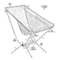
- FIG. 1 shows an assembled, light-weight, collapsible chair 10 that is appropriate for hiking and camping.
- Chair 10 is assembled around two molded-plastic tube connectors 11 .
- the ends of a central bar 12 fit into openings in two plastic bar connectors 11 .
- legs and support bars 13 are inserted into openings in the plastic bar connectors 11 in order to assemble chair 10 .
- the other ends of the support bars 13 are then inserted into corner pockets of a canvas seat back 14 .
- FIG. 2 shows collapsible chair 10 of FIG. 1 in a disassembled state.
- the legs and support bars 13 are removed from the bar connectors 11 and can be folded into the canvas seat back 14 .
- collapsible chair 10 can be conveniently packed into a small bag or back pack.
- collapsible chair 10 has the disadvantage of being unstable, particularly on the uneven ground typically present at outdoor activities, such as camping, hiking and fishing. Occupants of chair 10 have a tendency to fall backwards because the longer back support bars result in the center of gravity being well behind the central bar 12 .
- the plastic of the bar connectors 11 is not strong enough to hold the support bars 13 in place under the weight of the occupant. Especially after the occupant has been seated for an extended period, the plastic bar connectors 11 cannot prevent the back support bars from bending backwards, which can shift the center of gravity even behind the ends of the back legs.
- a compact, light-weight collapsible chair is sought that is nevertheless sturdy, stable and suitable for use on uneven ground.
- a sturdy, compact collapsible chair includes upper tubes, leg tubes, a central tube connector and a fabric seat back. All of the tubes are hollow and metal.
- the central tube connector has two first short tubes bent around a central cylinder from below and two second short tubes bent around the central cylinder from above.
- the central cylinder has a diameter that is larger than the diameter of the upper tubes, leg tubes and first and second short tubes.
- the two first short bent tubes are welded to the bottom of the central cylinder, and the two second short bent tubes are welded to the top of the central cylinder.
- Each pair of first and second bent tubes is also welded together.
- Upper holes are formed at the ends of the first tubes, and lower holes are formed at the ends of the second tubes.
- the upper tubes are formed from detachable sections.
- Each of the back upper tubes has an upper section, a middle section and a lower section.
- Each front upper tube has an upper section and a lower section.
- each upper tube is inserted into one of the upper holes in the first bent tubes, and the upper end of each of the leg tubes is inserted into one of the lower holes in the second bent tubes.
- Each of the lower ends of the upper tubes has a circular cross section that is dimensioned to fit snugly into the circular circumference of a corresponding upper hole.
- Upper ends of the upper tubes fit into tube receptacles in the seat back. No part of the upper tubes other than the upper and lower ends contacts any part of the collapsible chair.
- the two back upper tubes are longer than the two front upper tubes.
- the lower section of each of the two back upper tubes is curved, whereas both sections of each front upper tube are straight.
- a method of manufacturing the sturdy, collapsible chair includes forming tubes, a central tube connector and a seat back and then placing the tubes, connector and seat back in a bag that is less than one foot long.
- a plurality of upper tubes are formed in detachable sections. Each back upper tube has an upper section, a middle section and a lower section. The upper and middle sections are straight, whereas the lower section is bent.
- Each front upper tube has a straight upper section and a straight lower section.
- the upper tubes have lower ends and seat ends.
- a plurality of leg tubes are formed with upper ends and ground ends. The lower ends of the upper tubes and the upper ends of the leg tubes have outer diameters that are dimensioned to fit snugly into the inner diameters of the regular tube dimensions.
- the central tube connector is formed by bending first short tubes around a central cylinder from below and welding the first tubes to the central cylinder.
- Second tubes are bent around the central cylinder from above and are welded to the central cylinder.
- Upper holes with circular circumferences are disposed at the ends of the first bent tubes
- lower holes with circular circumferences are disposed at the ends of the second bent tubes.
- the circular cross sections of the lower ends of the upper tubes are dimensioned to fit snugly into the circular circumferences of the upper holes of the first bent tubes
- the upper ends of the leg tubes are dimensioned to fit snugly into the lower holes of the second bent tubes.
- An elastic cord is pulled through each of the tubes.
- An elastic cord is passes from each front upper tube, through an upper hole, through a first bent tube, out another upper hole and into a back upper tube.
- an elastic cord is passes from each front leg tube, through a lower hole, through a second bent tube, out another lower hole and into a back leg tube.
- the seat back has a plurality of tube receptacles disposed at locations on the seat back so as to fit over the seat ends of the upper tubes.
- FIG. 1 (prior art) is a perspective view of a collapsible chair assembled around two plastic bar connectors.
- FIG. 2 shows the components of the collapsible chair of FIG. 1 before they are assembled.
- FIG. 3 is a perspective view of an assembled sturdy, collapsible chair according to the present invention.
- FIG. 4 is a perspective view of one end of the central tube connector of the chair of FIG. 3 .
- FIG. 5 shows the central tube connector of the chair of FIG. 3 looking down the central axis of the central cylinder.
- FIG. 6 shows the frame of the chair of FIG. 3 in the collapsed state in the process of being assembled.
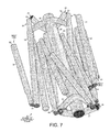
- FIG. 7 shows the tubes of the frame of the chair of FIG. 3 bunched up parallel to one another to be placed in a bag.
- FIG. 8 is a perspective view of the chair of FIG. 3 in the assembled state before the seat back is placed over the upper tubes.
- FIG. 9 shows an occupant sitting in the assembled collapsible chair of FIG. 3 .
- FIG. 10 is a flowchart of steps of a method of manufacturing the collapsible chair of FIG. 3 .
- FIG. 3 shows a sturdy, compact, collapsible chair 15 in an assembled state.
- Collapsible chair 15 can easily be disassembled and placed in a small bag that is less than a foot long.
- Collapsible chair 15 consists of four upper tubes 16 - 19 , four leg tubes 20 - 23 , a central tube connector 24 , four elastic cords with associated plugs, and a seat back 25 .
- the upper tubes 16 - 19 and leg tubes 20 - 23 are hollow tubes with circular cross sections.
- the back two upper tubes 18 - 19 are longer than the front two upper tubes 16 - 17 .
- the front two upper tubes 16 - 17 have detachable upper and lower sections, while the back two upper tubes 18 - 19 have detachable upper, middle and lower sections.
- the central tube connector 24 has a central cylinder 26 , two first bent tubes 27 - 28 , and two second bent tubes 29 - 30 .
- the upper tubes 16 - 19 , the leg tubes 20 - 23 , the central cylinder 26 , the two first bent tubes 27 - 28 , and two second bent tubes 29 - 30 are all made of aluminum, which is light weight but yet strong.
- the light-weight, compact, collapsible chair 15 which fits into a small bag, is suitable especially for hiking and camping.
- all of the tubes are made of steel, with is heavier but stronger than aluminum.
- the leg tubes 20 - 23 , the sections of the upper tubes 16 - 19 , the first bent tubes 27 - 28 , and second bent tubes 29 - 30 all have the same diameter.
- the diameter of central cylinder 26 is larger than the diameter of the other tubes.
- central cylinder 26 has an outer diameter of one inch, and the other tubes have an outer diameter of one half inch.
- One end of each of the leg tubes 20 - 23 and each section of the upper tubes 16 - 19 has a smaller outside diameter that fits inside the inner diameter of the regular tube dimensions.
- the lower end of the lower section of the upper tube 17 has a one-inch length with a three-eighths-inch outer diameter that fits inside the inner diameter of the first bent tube 28 .
- FIG. 4 is a perspective view of one end of the central tube connector 24 in more detail.
- the central tube connector 24 is formed by bending the first and second short tubes 27 - 30 around the central cylinder 26 .
- Each of the first short tubes 27 - 28 is bent around central cylinder 26 from below to form an open “U”.
- Two upper holes with circular circumferences are disposed at the ends of each first tube 27 - 28 .
- FIG. 4 shows upper hole 31 in first short tube 28 .
- the angle between the arms of the “U” is slightly less than ninety degrees.
- Each of the first tubes 27 - 28 is welded to the central cylinder 26 at the bottom of the cylinder such that the ends of each bent first tube slant up and outward by about thirty degrees from perpendicular to the central axis of the central cylinder 26 .
- FIG. 4 shows the weld 32 at the bottom of the central cylinder 26 that attaches the first tube 28 to the central cylinder.
- Each of the second short tubes 29 - 30 is bent around the central cylinder 26 from above and is welded to the central cylinder 26 at the top of the cylinder.
- the second tubes 29 - 30 are bent around the central cylinder 26 inside the locations where the first tubes 27 - 28 are bent around central cylinder 26 .
- each of the first tubes 27 , 28 is also welded to the corresponding second tube 29 , 30 near the ends of the short tubes.
- the ends of each bent second tube 29 - 30 slant down and outward by about thirty degrees from perpendicular to the central axis of central cylinder 26 .
- Two lower holes with circular circumferences are disposed at the ends of each second tube 29 - 30 .
- FIG. 5 shows the central tube connector 24 looking down the central axis of the central cylinder 26 .
- FIG. 5 shows how the two first short bent tubes 27 - 28 are bent around central cylinder 26 from below.
- Second short bent tube 30 is bent around central cylinder 26 from above.
- the two upper holes 31 , 34 with circular circumferences are shown at the ends of the first short bent tube 28 .
- the upper tubes 16 - 19 have lower ends and seat ends, and the leg tubes 20 - 23 have upper ends and bottom ends.
- FIG. 5 shows the lower end 35 of the lower section of the upper tube 17 and the lower end 36 of the lower section of the upper tube 18 .
- the lower ends of the upper tubes 16 - 19 are detachably connected to the first tubes 27 - 28 by being inserted into the upper holes.
- the lower end 35 of upper tube 17 is inserted into upper hole 31 of first tube 28
- the lower end 36 of upper tube 18 is inserted into upper hole 34 of first tube 28 .
- the upper ends of the leg tubes 20 - 23 are detachably connected to the second tubes 29 - 30 by being inserted into the lower holes.
- FIG. 6 shows the frame 37 of collapsible chair 15 in the collapsed state.
- the frame is made entirely of metal tubes.
- no additional manufacturing equipment or processes are required to work with materials other than the hollow metal tubing.
- no molds are required to make the plastic bar connectors 11 of the collapsible chair 10 of the prior art.
- the tubes themselves are used as a means for forming the holes into which the ends of other tubes are detachably connected to assemble the collapsible chair 15 .
- FIG. 6 shows that the shorter front two upper tubes 16 - 17 have detachable upper and lower sections, while the back two upper tubes 18 - 19 have detachable upper, middle and lower sections.
- front upper tube 17 has an upper section 38 and a lower section 39
- back upper tube 18 has an upper section 40 , a middle section 41 and a lower section 42 .
- the seat ends of the upper tubes 16 - 19 are opposite the lower ends 43 , 35 , 36 and 44 that fit snugly into the upper holes 45 , 31 , 34 and 46 , respectively.
- the circular cross section of each of the lower ends 43 , 35 , 36 and 44 is dimensioned to fit snugly into the circular circumference of the corresponding upper hole 45 , 31 , 34 and 46 .
- the seat ends of the upper tubes 16 - 19 are shown detachably connected to the tube receptacles 47 - 50 , respectively, at the four corners of the seat back 25 .
- the seat back 25 is made of stitched pieces of woven fabric, such as canvas.
- the seat back 25 is stretched so that the tube receptacles 47 - 50 will fit over the seat ends of the upper tubes 16 - 19 .
- the curved back upper tubes 18 - 19 can have only one orientation in the upper holes and still fit into the tube receptacles 47 - 50 .
- the upper tubes 16 - 19 are under some tension that pulls the seat ends together.
- the tube receptacles 47 - 50 are pockets sewn in the fabric of the seat back 25 .
- the tube receptacles 47 - 50 are hard plastic cylinders into which the seat ends of the upper tubes 16 - 19 slide. The plastic cylinders are either glued or stitched to the fabric of the seat back 25 . In the assembled state of collapsible chair 15 , no part of the upper tubes 16 - 19 other than the lower ends and the seat ends contacts any part of the collapsible chair. The bottom ends of the leg tubes 20 - 23 rest on the ground.
- FIG. 7 shows the upper tubes 16 - 19 , the leg tubes 20 - 23 and the central tube connector 24 in the collapsed state bunched up to be placed in a bag. Because the central cylinder 26 and each of the other tube sections is less than one foot long, the entire collapsible chair 15 can fit into a bag that is less than one foot long.
- the collapsed tubes of the frame 37 are rolled up in the seat back 25 before being inserted into the bag. In the collapsed state of FIG. 7 , all of the tubes 16 - 23 have been pulled out of the holes in the central tube connector 24 . In addition, the sections of the upper tubes 16 - 19 have been pulled apart. Elastic cords pass through all of the upper tubes, leg tubes, first bent tubes and second bent tubes.
- the elastic cords tend to pull the tube sections into one another and the upper tubes and leg tubes into the holes in the first bent tubes and the second bent tubes.
- the user can then align the tube sections with each other and with the upper and lower holes, and the tubes are pulled into the central tube connector 24 .
- the elastic cords tend to pull the tubes of the frame 37 into the assembled state.
- the tubes are held in place by the elastic cords.
- the ends of the elastic cords are attached to the inside of plugs that fit into the seat ends of the upper tubes 16 - 19 or into the bottom ends of the leg tubes 20 - 23 .
- An elastic cord passes from an end plug at the seat end of each front upper tube 16 - 17 , through one of the first bent tubes 27 - 28 and through a back upper tube 19 - 18 to an end plug at the seat end of the back upper tube.
- an elastic cord passes from a ground plug at the bottom end of each front leg tube 20 - 21 , through one of the second bent tubes 29 - 30 and through a back leg tube 23 - 22 to a ground plug at the bottom end of the corresponding back leg tube.
- portions of an elastic cord 51 can be seen in FIG. 7 that passes from an end plug 52 at the seat end of front upper tube 17 , through first bent tube 28 and through back upper tube 18 to an end plug 53 at the seat end of back upper tube 18 .
- FIG. 8 is a perspective view of the frame 37 of collapsible chair 15 in the assembled state before the tube receptacles at the corners of the seat back 25 have been slipped over the seat ends of the upper tubes 16 - 19 .
- FIG. 8 shows that the back upper tubes 18 - 19 with three sections have a first length that is longer than the second length of the front upper tubes 16 - 17 , which have only two sections.
- the longer back upper tubes 18 - 19 support the back of the seat back 25
- the shorter front upper tubes 16 - 17 support the seat of the seat back 25 upon which the user's legs rest.
- the lower sections 42 and 54 of each of the back upper tubes 18 and 19 are curved, whereas the middle and upper sections of the back upper tubes 18 and 19 are straight.
- collapsible chair 15 does not have a tendency to fall backwards as is the case with prior art collapsible chair 10 , whose back bars are entirely straight from the plastic bar connectors 11 to the corner pockets of the seat back 14 .
- bending the lower sections 42 , 54 moves the back upper tubes 18 , 19 away from the bottom of the seat back 25 , which is pressed down by the occupant. It would be uncomfortable for the occupant to feel the back support tubes when sinking into the chair if the back support tubes were entirely straight.
- FIG. 9 shows an occupant 57 sitting in the assembled collapsible chair 15 .
- FIG. 9 illustrates that the center of gravity of the occupant 57 is in front of the central cylinder 26 even though the occupant is resting on the back of the seat.
- the bent lower sections 42 , 54 remain a significant distance away from the bottom of the seat back 25 that is pressed down by the occupant 57 . Even if the seat back 25 were larger and lower slung than in FIG. 9 , the occupant 57 would still not press against the back upper tubes 18 - 19 .
- the second bent tubes 29 - 30 are metal welded to the metal central cylinder 26 and are therefore stronger than the plastic bar connectors 11 of the prior art chair 10 .
- the strength of a plastic bar connector 11 is often insufficient to maintain the angle between each pair of front and back leg bars, and the leg bars warp to a more open angle than the plastic bar connector 11 can hold.
- Each of the second bent tubes 29 , 30 of sturdy chair 15 is strong enough to hold its pair of leg tubes 20 , 23 and 21 , 22 , respectively, under the weight of the occupant 57 at an angle that slants down and outward by about thirty degrees from perpendicular to the central axis of central cylinder 26 .
- the bottom ends of the leg tubes 20 - 23 are spaced farther apart and provide a wider and more stable base than the leg bars of prior art chair 10 , which do not slant to the sides as is evident in FIG. 1 .
- FIG. 10 is a flowchart illustrating steps 60 - 66 of a method of manufacturing collapsible chair 15 .
- the detachable sections of the upper tubes 16 - 19 are formed from hollow metal tubes with circular cross sections.
- the metal can be aluminum or steel.
- Each of the sections of the upper tubes 16 - 19 has a lower end with a smaller outer diameter.
- the lower end of each tube section is dimensioned to fit snugly into the hole formed by the end of the tube below.
- the lower end of the upper section 40 of tube 18 is dimensioned to fit snugly into the hole at the top of the middle section 41 .
- the lower end of the middle section 41 of tube 18 is dimensioned to fit snugly into the hole at the top of the lower section 42 .
- the lower end of lower section 42 is the lower end of upper tube 18 .
- the leg tubes 20 - 23 are also formed from hollow metal tubes with the same diameter as the upper tubes 16 - 19 .
- Each leg tube has only a single section.
- the leg tubes 20 - 23 have upper ends and lower ground ends. At the upper ends of the leg tubes 20 - 23 there is an upper portion that has a smaller outer diameter than the rest of the leg tubes.
- the first short bent tubes 27 - 28 are bent around the central cylinder 26 from below and are welded to the central cylinder 26 at the bottom of the cylinder.
- the upper holes 45 - 46 have circular circumferences and are disposed at the ends of the first tube 27
- the upper holes 31 , 34 have circular circumferences and are disposed at the ends of the first tube 28 .
- the circular cross sections of the lower ends of the upper tubes 16 - 19 are dimensioned to fit snugly into the circular circumferences of the upper holes 31 , 34 , 43 , 46 .
- step 63 the second short bent tubes 29 - 30 are bent around the central cylinder 26 from above and are welded to the central cylinder 26 at the top of the cylinder.
- Lower holes with circular circumferences are disposed at the ends of the second tubes 29 - 30 .
- the circular cross sections of the upper ends of the leg tubes 20 - 23 are dimensioned to fit snugly into the circular circumferences of the lower holes.
- the seat back 25 is made with the four tube receptacles 47 - 50 disposed at the corners of the approximately rectangular seat back so as to fit over the seat ends of the upper tubes 16 - 19 .
- the seat back 25 is made by stitching together various pieces of fabric or plastic.
- the tube receptacles 47 - 50 can be sewn as pockets into the seat back or they can be molded plastic cylinders that are glued or stitched to the corners of the seat back 25 .
- an elastic cord is pulled through each pair of front and back upper tubes and each pair of front and back leg tubes.
- the two elastic cords that pass through the front and back upper tubes also pass through the first short bent tubes 27 - 28 .
- the two elastic cords that pass through each pair of leg tubes also pass through the second short bent tubes 29 - 30 .
- an elastic cord 51 that attaches to an end plug 53 at the seat end 55 of upper tube 18 is pulled through the sections of back upper tube 18 , into upper hole 34 , through first short bent tube 28 , out upper hole 31 , through the sections of front upper tube 17 and attaches to an end plug 52 at the seat end of tube 17 .
- leg tube 22 another elastic cord that attaches to a ground plug of leg tube 22 is pulled through tube 22 , into a lower hole, through second short bent tube 30 , out another lower hole, through leg tube 21 and attaches to a ground plug at the bottom end of front leg tube 21 .
- step 66 all of the tube sections are detached from one another and the tubes are detached from central tube connector 24 .
- the tubes are then oriented relatively parallel to one another, as shown in FIG. 7 .
- the tubes are then rolled up in the seat back 25 , and the upper tubes 16 - 19 , the leg tubes 20 - 23 , the central cylinder 26 , the first short bent tubes 27 - 28 , the second short bent tubes 29 - 30 and the seat back 25 are placed in a bag. Because each of the central cylinder 26 , the tube sections and the leg tubes is less than twelve inches long, the components of collapsible chair 15 fit in a bag that is less than a foot long, which is ideal for camping and hiking. The bag is less than six inches in diameter.
- the user removes the tubes and the seat back 25 from the bag and unwraps the seat back from around the tubes.
- the user then aligns the tube sections with each other and with the upper and lower holes.
- the elastic cords tend to pull the tube sections into one another and the upper tubes into the upper holes in the first bent tubes.
- the elastic cords also pull the leg tubes into the lower holes in the second bent tubes.
- the back upper tubes 18 - 19 are formed when the upper sections are detachably connected to the middle sections, and the middle sections are detachably connected to the lower sections.
- the front upper tubes 16 - 17 are formed when the upper sections are detachably connected to the lower sections.
- the lower ends of the upper tubes 16 - 19 are detachably connected to the first tubes 27 - 28 by being inserted into the upper holes 45 , 46 , 34 , 31 , and the upper ends of the leg tubes 20 - 23 are detachably connected to the second tubes 29 - 30 by being inserted into the lower holes.
Landscapes
- Health & Medical Sciences (AREA)
- Dentistry (AREA)
- General Health & Medical Sciences (AREA)
- Chair Legs, Seat Parts, And Backrests (AREA)
Abstract
A collapsible chair includes upper tubes, leg tubes, a central tube connector and a seat back. The tube connector has two first tubes bent around a central cylinder from below and two second tubes bent around the central cylinder from above. The first and second tubes are welded to the central cylinder. Upper holes are formed by the ends of the first tubes, and lower holes are formed by the ends of the second tubes. Lower ends of the upper tubes are inserted into the upper holes, and upper ends of the leg tubes are inserted into the lower holes. Upper ends of the upper tubes fit into tube receptacles in the seat back. No part of the upper tubes other than the upper and lower ends contacts any part of the chair. The two back upper tubes are bent and are longer than the two straight front upper tubes.
Description
- This application is based on and hereby claims the benefit under 35 U.S.C. §119 from Korean Patent Application No. 2020140008443, filed on Nov. 18, 2014, in the Republic of Korea, the subject matter of which is incorporated herein by reference. This application is a continuation-in-part of Korean Application No. 2020140008443. In addition, this application is a continuation-in-part of, and claims priority under 35 U.S.C. §120 from, nonprovisional U.S. patent application Ser. No. 29/507,520 entitled “Collapsible Chair with Poles Extending from a Central Bar,” filed on Oct. 28, 2014, the subject matter of which is incorporated herein by reference.
- The described embodiments relate to chairs, and more particularly to portable, collapsible chairs that are suitable for camping, fishing, outdoor concerts and sporting events.
- Portable chairs are convenient during outdoor activities at which seating is otherwise unavailable. Folding chairs that are commonly used in the home to save space are not sufficiently portable for most outdoor activities, such as camping, hiking, fishing, outdoor concerts and sporting events. A portable chair for outdoor activities should be light weight and compact. For example, a chair used for hiking or camping should advantageously fit into a back pack and not weigh down the hiker. The typical tube-and-canvas folding chairs used at field-side sporting events are simply too large and heavy to take along on a hike. A smaller and lighter folding chair would also be more convenient even at events on a field that is a short distance from the trunk of the user's car.
-
FIG. 1 (prior art) shows an assembled, light-weight,collapsible chair 10 that is appropriate for hiking and camping.Chair 10 is assembled around two molded-plastic tube connectors 11. The ends of acentral bar 12 fit into openings in twoplastic bar connectors 11. In addition, legs andsupport bars 13 are inserted into openings in theplastic bar connectors 11 in order to assemblechair 10. The other ends of thesupport bars 13 are then inserted into corner pockets of a canvas seat back 14. -
FIG. 2 (prior art) showscollapsible chair 10 ofFIG. 1 in a disassembled state. The legs andsupport bars 13 are removed from thebar connectors 11 and can be folded into the canvas seat back 14. Thus,collapsible chair 10 can be conveniently packed into a small bag or back pack. However,collapsible chair 10 has the disadvantage of being unstable, particularly on the uneven ground typically present at outdoor activities, such as camping, hiking and fishing. Occupants ofchair 10 have a tendency to fall backwards because the longer back support bars result in the center of gravity being well behind thecentral bar 12. In addition, the plastic of thebar connectors 11 is not strong enough to hold thesupport bars 13 in place under the weight of the occupant. Especially after the occupant has been seated for an extended period, theplastic bar connectors 11 cannot prevent the back support bars from bending backwards, which can shift the center of gravity even behind the ends of the back legs. - A compact, light-weight collapsible chair is sought that is nevertheless sturdy, stable and suitable for use on uneven ground.
- A sturdy, compact collapsible chair includes upper tubes, leg tubes, a central tube connector and a fabric seat back. All of the tubes are hollow and metal. The central tube connector has two first short tubes bent around a central cylinder from below and two second short tubes bent around the central cylinder from above. The central cylinder has a diameter that is larger than the diameter of the upper tubes, leg tubes and first and second short tubes. The two first short bent tubes are welded to the bottom of the central cylinder, and the two second short bent tubes are welded to the top of the central cylinder. Each pair of first and second bent tubes is also welded together. Upper holes are formed at the ends of the first tubes, and lower holes are formed at the ends of the second tubes. The upper tubes are formed from detachable sections. Each of the back upper tubes has an upper section, a middle section and a lower section. Each front upper tube has an upper section and a lower section.
- The lower end of each upper tube is inserted into one of the upper holes in the first bent tubes, and the upper end of each of the leg tubes is inserted into one of the lower holes in the second bent tubes. Each of the lower ends of the upper tubes has a circular cross section that is dimensioned to fit snugly into the circular circumference of a corresponding upper hole. Upper ends of the upper tubes fit into tube receptacles in the seat back. No part of the upper tubes other than the upper and lower ends contacts any part of the collapsible chair. The two back upper tubes are longer than the two front upper tubes. The lower section of each of the two back upper tubes is curved, whereas both sections of each front upper tube are straight.
- A method of manufacturing the sturdy, collapsible chair includes forming tubes, a central tube connector and a seat back and then placing the tubes, connector and seat back in a bag that is less than one foot long. A plurality of upper tubes are formed in detachable sections. Each back upper tube has an upper section, a middle section and a lower section. The upper and middle sections are straight, whereas the lower section is bent. Each front upper tube has a straight upper section and a straight lower section. The upper tubes have lower ends and seat ends. A plurality of leg tubes are formed with upper ends and ground ends. The lower ends of the upper tubes and the upper ends of the leg tubes have outer diameters that are dimensioned to fit snugly into the inner diameters of the regular tube dimensions.
- The central tube connector is formed by bending first short tubes around a central cylinder from below and welding the first tubes to the central cylinder. Second tubes are bent around the central cylinder from above and are welded to the central cylinder. Upper holes with circular circumferences are disposed at the ends of the first bent tubes, and lower holes with circular circumferences are disposed at the ends of the second bent tubes. The circular cross sections of the lower ends of the upper tubes are dimensioned to fit snugly into the circular circumferences of the upper holes of the first bent tubes, and the upper ends of the leg tubes are dimensioned to fit snugly into the lower holes of the second bent tubes. An elastic cord is pulled through each of the tubes. An elastic cord is passes from each front upper tube, through an upper hole, through a first bent tube, out another upper hole and into a back upper tube. Similarly, an elastic cord is passes from each front leg tube, through a lower hole, through a second bent tube, out another lower hole and into a back leg tube. The seat back has a plurality of tube receptacles disposed at locations on the seat back so as to fit over the seat ends of the upper tubes.
- Other embodiments and advantages are described in the detailed description below. This summary does not purport to define the invention. The invention is defined by the claims.
- The accompanying drawings, where like numerals indicate like components, illustrate embodiments of the invention.
-
FIG. 1 (prior art) is a perspective view of a collapsible chair assembled around two plastic bar connectors. -
FIG. 2 (prior art) shows the components of the collapsible chair ofFIG. 1 before they are assembled. -
FIG. 3 is a perspective view of an assembled sturdy, collapsible chair according to the present invention. -
FIG. 4 is a perspective view of one end of the central tube connector of the chair ofFIG. 3 . -
FIG. 5 shows the central tube connector of the chair ofFIG. 3 looking down the central axis of the central cylinder. -
FIG. 6 shows the frame of the chair ofFIG. 3 in the collapsed state in the process of being assembled. -
FIG. 7 shows the tubes of the frame of the chair ofFIG. 3 bunched up parallel to one another to be placed in a bag. -
FIG. 8 is a perspective view of the chair ofFIG. 3 in the assembled state before the seat back is placed over the upper tubes. -
FIG. 9 shows an occupant sitting in the assembled collapsible chair ofFIG. 3 . -
FIG. 10 is a flowchart of steps of a method of manufacturing the collapsible chair ofFIG. 3 . - Reference will now be made in detail to some embodiments of the invention, examples of which are illustrated in the accompanying drawings.
-
FIG. 3 shows a sturdy, compact,collapsible chair 15 in an assembled state.Collapsible chair 15 can easily be disassembled and placed in a small bag that is less than a foot long.Collapsible chair 15 consists of four upper tubes 16-19, four leg tubes 20-23, acentral tube connector 24, four elastic cords with associated plugs, and a seat back 25. The upper tubes 16-19 and leg tubes 20-23 are hollow tubes with circular cross sections. The back two upper tubes 18-19 are longer than the front two upper tubes 16-17. The front two upper tubes 16-17 have detachable upper and lower sections, while the back two upper tubes 18-19 have detachable upper, middle and lower sections. Thecentral tube connector 24 has acentral cylinder 26, two first bent tubes 27-28, and two second bent tubes 29-30. In one embodiment, the upper tubes 16-19, the leg tubes 20-23, thecentral cylinder 26, the two first bent tubes 27-28, and two second bent tubes 29-30 are all made of aluminum, which is light weight but yet strong. Thus, the light-weight, compact,collapsible chair 15, which fits into a small bag, is suitable especially for hiking and camping. In another embodiment, all of the tubes are made of steel, with is heavier but stronger than aluminum. - The leg tubes 20-23, the sections of the upper tubes 16-19, the first bent tubes 27-28, and second bent tubes 29-30 all have the same diameter. The diameter of
central cylinder 26 is larger than the diameter of the other tubes. In one embodiment,central cylinder 26 has an outer diameter of one inch, and the other tubes have an outer diameter of one half inch. One end of each of the leg tubes 20-23 and each section of the upper tubes 16-19 has a smaller outside diameter that fits inside the inner diameter of the regular tube dimensions. For example, the lower end of the lower section of theupper tube 17 has a one-inch length with a three-eighths-inch outer diameter that fits inside the inner diameter of the firstbent tube 28. -
FIG. 4 is a perspective view of one end of thecentral tube connector 24 in more detail. Thecentral tube connector 24 is formed by bending the first and second short tubes 27-30 around thecentral cylinder 26. Each of the first short tubes 27-28 is bent aroundcentral cylinder 26 from below to form an open “U”. Two upper holes with circular circumferences are disposed at the ends of each first tube 27-28. For example,FIG. 4 showsupper hole 31 in firstshort tube 28. The angle between the arms of the “U” is slightly less than ninety degrees. Each of the first tubes 27-28 is welded to thecentral cylinder 26 at the bottom of the cylinder such that the ends of each bent first tube slant up and outward by about thirty degrees from perpendicular to the central axis of thecentral cylinder 26.FIG. 4 shows theweld 32 at the bottom of thecentral cylinder 26 that attaches thefirst tube 28 to the central cylinder. Each of the second short tubes 29-30 is bent around thecentral cylinder 26 from above and is welded to thecentral cylinder 26 at the top of the cylinder. The second tubes 29-30 are bent around thecentral cylinder 26 inside the locations where the first tubes 27-28 are bent aroundcentral cylinder 26.FIG. 4 shows theweld 33 at the top ofcentral cylinder 26 that attaches thesecond tube 30 to the central cylinder. Each of thefirst tubes second tube central cylinder 26. Two lower holes with circular circumferences are disposed at the ends of each second tube 29-30. -
FIG. 5 shows thecentral tube connector 24 looking down the central axis of thecentral cylinder 26.FIG. 5 shows how the two first short bent tubes 27-28 are bent aroundcentral cylinder 26 from below. Second shortbent tube 30 is bent aroundcentral cylinder 26 from above. The twoupper holes bent tube 28. The upper tubes 16-19 have lower ends and seat ends, and the leg tubes 20-23 have upper ends and bottom ends.FIG. 5 shows thelower end 35 of the lower section of theupper tube 17 and thelower end 36 of the lower section of theupper tube 18. To assemble thecollapsible chair 15, the lower ends of the upper tubes 16-19 are detachably connected to the first tubes 27-28 by being inserted into the upper holes. For example, thelower end 35 ofupper tube 17 is inserted intoupper hole 31 offirst tube 28, and thelower end 36 ofupper tube 18 is inserted intoupper hole 34 offirst tube 28. Similarly, to assemble thecollapsible chair 15, the upper ends of the leg tubes 20-23 are detachably connected to the second tubes 29-30 by being inserted into the lower holes. -
FIG. 6 shows theframe 37 ofcollapsible chair 15 in the collapsed state. The frame is made entirely of metal tubes. Thus, no additional manufacturing equipment or processes are required to work with materials other than the hollow metal tubing. For example, no molds are required to make theplastic bar connectors 11 of thecollapsible chair 10 of the prior art. The tubes themselves are used as a means for forming the holes into which the ends of other tubes are detachably connected to assemble thecollapsible chair 15.FIG. 6 shows that the shorter front two upper tubes 16-17 have detachable upper and lower sections, while the back two upper tubes 18-19 have detachable upper, middle and lower sections. For example, frontupper tube 17 has anupper section 38 and alower section 39, and backupper tube 18 has anupper section 40, amiddle section 41 and alower section 42. The seat ends of the upper tubes 16-19 are opposite the lower ends 43, 35, 36 and 44 that fit snugly into theupper holes upper hole - Returning to
FIG. 3 , the seat ends of the upper tubes 16-19 are shown detachably connected to the tube receptacles 47-50, respectively, at the four corners of the seat back 25. The seat back 25 is made of stitched pieces of woven fabric, such as canvas. The seat back 25 is stretched so that the tube receptacles 47-50 will fit over the seat ends of the upper tubes 16-19. The curved back upper tubes 18-19 can have only one orientation in the upper holes and still fit into the tube receptacles 47-50. Thus, in the assembled state, the upper tubes 16-19 are under some tension that pulls the seat ends together. In one embodiment, the tube receptacles 47-50 are pockets sewn in the fabric of the seat back 25. In another embodiment, the tube receptacles 47-50 are hard plastic cylinders into which the seat ends of the upper tubes 16-19 slide. The plastic cylinders are either glued or stitched to the fabric of the seat back 25. In the assembled state ofcollapsible chair 15, no part of the upper tubes 16-19 other than the lower ends and the seat ends contacts any part of the collapsible chair. The bottom ends of the leg tubes 20-23 rest on the ground. -
FIG. 7 shows the upper tubes 16-19, the leg tubes 20-23 and thecentral tube connector 24 in the collapsed state bunched up to be placed in a bag. Because thecentral cylinder 26 and each of the other tube sections is less than one foot long, the entirecollapsible chair 15 can fit into a bag that is less than one foot long. The collapsed tubes of theframe 37 are rolled up in the seat back 25 before being inserted into the bag. In the collapsed state ofFIG. 7 , all of the tubes 16-23 have been pulled out of the holes in thecentral tube connector 24. In addition, the sections of the upper tubes 16-19 have been pulled apart. Elastic cords pass through all of the upper tubes, leg tubes, first bent tubes and second bent tubes. When the tubes of theframe 37 are removed from their bag, the elastic cords tend to pull the tube sections into one another and the upper tubes and leg tubes into the holes in the first bent tubes and the second bent tubes. The user can then align the tube sections with each other and with the upper and lower holes, and the tubes are pulled into thecentral tube connector 24. Thus, the elastic cords tend to pull the tubes of theframe 37 into the assembled state. Once in the assembled state, the tubes are held in place by the elastic cords. The ends of the elastic cords are attached to the inside of plugs that fit into the seat ends of the upper tubes 16-19 or into the bottom ends of the leg tubes 20-23. An elastic cord passes from an end plug at the seat end of each front upper tube 16-17, through one of the first bent tubes 27-28 and through a back upper tube 19-18 to an end plug at the seat end of the back upper tube. In addition, an elastic cord passes from a ground plug at the bottom end of each front leg tube 20-21, through one of the second bent tubes 29-30 and through a back leg tube 23-22 to a ground plug at the bottom end of the corresponding back leg tube. Thus, there are four elastic cords that each pass through the means 27-30 for forming the upper and lower holes. For example, portions of anelastic cord 51 can be seen inFIG. 7 that passes from anend plug 52 at the seat end of frontupper tube 17, through firstbent tube 28 and through backupper tube 18 to anend plug 53 at the seat end of backupper tube 18. -
FIG. 8 is a perspective view of theframe 37 ofcollapsible chair 15 in the assembled state before the tube receptacles at the corners of the seat back 25 have been slipped over the seat ends of the upper tubes 16-19.FIG. 8 shows that the back upper tubes 18-19 with three sections have a first length that is longer than the second length of the front upper tubes 16-17, which have only two sections. The longer back upper tubes 18-19 support the back of the seat back 25, whereas the shorter front upper tubes 16-17 support the seat of the seat back 25 upon which the user's legs rest. Thelower sections upper tubes upper tubes upper tubes lower sections central cylinder 26, and the center of gravity of the occupant ofcollapsible chair 15 is moved in front of thecentral cylinder 26. Thus, bending thelower sections central cylinder 26 even through the back upper tubes 18-19 that support the back of the seat are significantly longer than the front upper tubes 16-17. The occupant ofcollapsible chair 15 does not have a tendency to fall backwards as is the case with prior artcollapsible chair 10, whose back bars are entirely straight from theplastic bar connectors 11 to the corner pockets of the seat back 14. In addition, bending thelower sections upper tubes -
FIG. 9 shows anoccupant 57 sitting in the assembledcollapsible chair 15.FIG. 9 illustrates that the center of gravity of theoccupant 57 is in front of thecentral cylinder 26 even though the occupant is resting on the back of the seat. Moreover, the bentlower sections occupant 57. Even if the seat back 25 were larger and lower slung than inFIG. 9 , theoccupant 57 would still not press against the back upper tubes 18-19. - The second bent tubes 29-30 are metal welded to the metal
central cylinder 26 and are therefore stronger than theplastic bar connectors 11 of theprior art chair 10. In addition, the strength of aplastic bar connector 11 is often insufficient to maintain the angle between each pair of front and back leg bars, and the leg bars warp to a more open angle than theplastic bar connector 11 can hold. Each of the secondbent tubes sturdy chair 15 is strong enough to hold its pair ofleg tubes occupant 57 at an angle that slants down and outward by about thirty degrees from perpendicular to the central axis ofcentral cylinder 26. Thus, the bottom ends of the leg tubes 20-23 are spaced farther apart and provide a wider and more stable base than the leg bars ofprior art chair 10, which do not slant to the sides as is evident inFIG. 1 . -
FIG. 10 is a flowchart illustrating steps 60-66 of a method of manufacturingcollapsible chair 15. In afirst step 60, the detachable sections of the upper tubes 16-19 are formed from hollow metal tubes with circular cross sections. The metal can be aluminum or steel. Each of the sections of the upper tubes 16-19 has a lower end with a smaller outer diameter. The lower end of each tube section is dimensioned to fit snugly into the hole formed by the end of the tube below. For example, the lower end of theupper section 40 oftube 18 is dimensioned to fit snugly into the hole at the top of themiddle section 41. Similarly, the lower end of themiddle section 41 oftube 18 is dimensioned to fit snugly into the hole at the top of thelower section 42. The lower end oflower section 42 is the lower end ofupper tube 18. - In
step 61, the leg tubes 20-23 are also formed from hollow metal tubes with the same diameter as the upper tubes 16-19. Each leg tube has only a single section. The leg tubes 20-23 have upper ends and lower ground ends. At the upper ends of the leg tubes 20-23 there is an upper portion that has a smaller outer diameter than the rest of the leg tubes. - In
step 62, the first short bent tubes 27-28 are bent around thecentral cylinder 26 from below and are welded to thecentral cylinder 26 at the bottom of the cylinder. The upper holes 45-46 have circular circumferences and are disposed at the ends of thefirst tube 27, and theupper holes first tube 28. The circular cross sections of the lower ends of the upper tubes 16-19 are dimensioned to fit snugly into the circular circumferences of theupper holes - In
step 63, the second short bent tubes 29-30 are bent around thecentral cylinder 26 from above and are welded to thecentral cylinder 26 at the top of the cylinder. Lower holes with circular circumferences are disposed at the ends of the second tubes 29-30. The circular cross sections of the upper ends of the leg tubes 20-23 are dimensioned to fit snugly into the circular circumferences of the lower holes. - In
step 64, the seat back 25 is made with the four tube receptacles 47-50 disposed at the corners of the approximately rectangular seat back so as to fit over the seat ends of the upper tubes 16-19. The seat back 25 is made by stitching together various pieces of fabric or plastic. The tube receptacles 47-50 can be sewn as pockets into the seat back or they can be molded plastic cylinders that are glued or stitched to the corners of the seat back 25. - In
step 65, an elastic cord is pulled through each pair of front and back upper tubes and each pair of front and back leg tubes. The two elastic cords that pass through the front and back upper tubes also pass through the first short bent tubes 27-28. The two elastic cords that pass through each pair of leg tubes also pass through the second short bent tubes 29-30. For example, anelastic cord 51 that attaches to anend plug 53 at theseat end 55 ofupper tube 18 is pulled through the sections of backupper tube 18, intoupper hole 34, through first shortbent tube 28, outupper hole 31, through the sections of frontupper tube 17 and attaches to anend plug 52 at the seat end oftube 17. Similarly, another elastic cord that attaches to a ground plug ofleg tube 22 is pulled throughtube 22, into a lower hole, through second shortbent tube 30, out another lower hole, throughleg tube 21 and attaches to a ground plug at the bottom end offront leg tube 21. - In
step 66, all of the tube sections are detached from one another and the tubes are detached fromcentral tube connector 24. The tubes are then oriented relatively parallel to one another, as shown inFIG. 7 . The tubes are then rolled up in the seat back 25, and the upper tubes 16-19, the leg tubes 20-23, thecentral cylinder 26, the first short bent tubes 27-28, the second short bent tubes 29-30 and the seat back 25 are placed in a bag. Because each of thecentral cylinder 26, the tube sections and the leg tubes is less than twelve inches long, the components ofcollapsible chair 15 fit in a bag that is less than a foot long, which is ideal for camping and hiking. The bag is less than six inches in diameter. - To assemble the
collapsible chair 15, the user removes the tubes and the seat back 25 from the bag and unwraps the seat back from around the tubes. The user then aligns the tube sections with each other and with the upper and lower holes. The elastic cords tend to pull the tube sections into one another and the upper tubes into the upper holes in the first bent tubes. The elastic cords also pull the leg tubes into the lower holes in the second bent tubes. The back upper tubes 18-19 are formed when the upper sections are detachably connected to the middle sections, and the middle sections are detachably connected to the lower sections. The front upper tubes 16-17 are formed when the upper sections are detachably connected to the lower sections. To assemble thecollapsible chair 15, the lower ends of the upper tubes 16-19 are detachably connected to the first tubes 27-28 by being inserted into theupper holes - Although certain specific exemplary embodiments are described above in order to illustrate the invention, the invention is not limited to the specific embodiments. Accordingly, various modifications, adaptations, and combinations of various features of the described embodiments can be practiced without departing from the scope of the invention as set forth in the claims.
Claims (20)
1. A collapsible chair comprising:
upper tubes with lower ends and seat ends, wherein the lower ends have circular cross setions;
leg tubes with upper ends;
a seat back with tube receptacles;
a central cylinder;
two first short bent tubes that bend around the central cylinder from below and that are welded to the central cylinder, wherein four upper holes with circular circumferences are formed at ends of the first tubes; and
two second short bent tubes that bend around the central cylinder from above and that are welded to the central cylinder, wherein four lower holes with circular circumferences are formed at ends of the second tubes, wherein the lower ends of the upper tubes are detachably connected to the first bent tubes by being inserted into the upper holes, wherein the upper ends of the leg tubes are detachably connected to the second bent tubes by being inserted into the lower holes, wherein the seat ends of the upper tubes are detachably connected to the tube receptacles, and wherein no part of the upper tubes other than the lower ends and the seat ends contacts any part of the collapsible chair.
2. The collapsible chair of claim 1 , wherein the upper tubes consist of two tubes of a first length and two tubes of a second length, and wherein the first length is longer than the second length.
3. The collapsible chair of claim 2 , wherein each of the two tubes of the first length is bent, and wherein neither of the two tubes of the second length is bent.
4. The collapsible chair of claim 2 , wherein each of the upper tubes of the first length has a lower section, a middle section and an upper section, wherein the lower end of each upper tube of the first length is disposed on the lower section of the upper tube, wherein each lower section is curved, and wherein each middle section and each upper section is straight.
5. The collapsible chair of claim 1 , wherein the central cylinder has a diameter that is larger than the diameter of the upper tubes.
6. The collapsible chair of claim 1 , wherein each of the upper tubes is comprised of detachable sections.
7. The collapsible chair of claim 1 , wherein the circular cross section of each of the lower ends is dimensioned to fit snugly into the circular circumference of a corresponding upper hole.
8. The collapsible chair of claim 1 , wherein the upper tubes consist of four tubes, and wherein the seat ends fit into the tube receptacles at four corners of the seat back.
9. The collapsible chair of claim 1 , wherein the seat back is made of fabric.
10. The collapsible chair of claim 1 , further comprising:
an elastic cord that passes through one of the first short bent tubes and into one of the upper tubes.
11. A collapsible chair comprising:
a seat back with tube receptacles; and
a frame made of metal tubes, wherein the frame comprises:
upper tubes with lower ends and seat ends, wherein the lower ends have circular cross sections;
a central tube whose diameter is larger than that of the upper tubes; and
means for forming upper holes with circular circumferences, wherein the lower ends of the upper tubes are detachably connected to the means by being inserted into the upper holes, wherein the means bends around and is welded to the central cylinder, and wherein the seat ends of the upper tubes are detachably connected to the tube receptacles.
12. The collapsible chair of claim 11 , further comprising:
an elastic cord that passes through one of the upper tubes and into the means.
13. The collapsible chair of claim 11 , wherein the frame further comprises leg tubes with upper ends, wherein the means is also for forming lower holes with circular circumferences, and wherein the upper ends of the leg tubes are detachably connected to the means by being inserted into the lower holes.
14. The collapsible chair of claim 11 , wherein the upper tubes include two tubes of a first length and two tubes of a second length, and wherein the first length is longer than the second length.
15. The collapsible chair of claim 14 , wherein each of the two tubes of the first length is bent, and wherein neither of the two tubes of the second length is bent.
16. The collapsible chair of claim 14 , wherein each of the upper tubes of the first length has a lower section, a middle section and an upper section, wherein the lower end of each upper tube of the first length is disposed on the lower section of the upper tube, wherein each lower section is bent, and wherein each middle section and each upper section is not bent.
17. A method comprising:
forming upper tubes with lower ends and seat ends, wherein the upper tubes are formed in sections, and wherein the lower ends have circular cross setions;
forming leg tubes with upper ends;
bending first tubes around a central cylinder from below and welding the first tubes to the central cylinder, wherein upper holes with circular circumferences are disposed at ends of the first tubes, and wherein the circular cross sections of the lower ends are dimensioned to fit snugly into the circular circumferences of the upper holes;
bending second tubes around the central cylinder from above and welding the second tubes to the central cylinder, wherein lower holes with circular circumferences are disposed at ends of the second tubes, and wherein the upper ends of the leg tubes are dimensioned to fit snugly into the lower holes; and
making a seat back with tube receptacles disposed at locations on the seat back so as to fit over the seat ends of the upper tubes.
18. The method of claim 17 , further comprising:
pulling an elastic cord through one of the first tubes and into one of the upper tubes.
19. The method of claim 17 , wherein the central cylinder has a diameter that is larger than that of the upper tubes.
20. The method of claim 17 , further comprising:
placing the upper tubes, the leg tubes, the central cylinder, the first tubes, the second tubes and the seat back in a bag that is less than one foot long.
Priority Applications (1)
| Application Number | Priority Date | Filing Date | Title |
|---|---|---|---|
| US14/589,354 US20160113402A1 (en) | 2014-10-28 | 2015-01-05 | Sturdy, Compact, Collapsible Camping Chair |
Applications Claiming Priority (4)
| Application Number | Priority Date | Filing Date | Title |
|---|---|---|---|
| US29/507,520 USD771986S1 (en) | 2014-10-28 | 2014-10-28 | Collapsible chair with poles extending from a central bar |
| KR20140008443U KR200476869Y1 (en) | 2014-11-18 | 2014-11-18 | Frame assembly of simple chair |
| KR2020140008443 | 2014-11-18 | ||
| US14/589,354 US20160113402A1 (en) | 2014-10-28 | 2015-01-05 | Sturdy, Compact, Collapsible Camping Chair |
Related Parent Applications (1)
| Application Number | Title | Priority Date | Filing Date |
|---|---|---|---|
| US29/507,520 Continuation-In-Part USD771986S1 (en) | 2014-10-28 | 2014-10-28 | Collapsible chair with poles extending from a central bar |
Publications (1)
| Publication Number | Publication Date |
|---|---|
| US20160113402A1 true US20160113402A1 (en) | 2016-04-28 |
Family
ID=55790945
Family Applications (1)
| Application Number | Title | Priority Date | Filing Date |
|---|---|---|---|
| US14/589,354 Abandoned US20160113402A1 (en) | 2014-10-28 | 2015-01-05 | Sturdy, Compact, Collapsible Camping Chair |
Country Status (1)
| Country | Link |
|---|---|
| US (1) | US20160113402A1 (en) |
Cited By (39)
| Publication number | Priority date | Publication date | Assignee | Title |
|---|---|---|---|---|
| USD771986S1 (en) * | 2014-10-28 | 2016-11-22 | FIMAX International Co., Ltd | Collapsible chair with poles extending from a central bar |
| US9782006B2 (en) * | 2015-06-01 | 2017-10-10 | Recreational Equipment, Inc. | Collapsible rocking chair |
| NL2018983A (en) * | 2016-08-03 | 2018-02-09 | Zhejiang Hengfeng Top Leisure Co Ltd | Compact collapsible chair |
| USD815448S1 (en) * | 2017-03-12 | 2018-04-17 | Xingfang Jin | Folding chair |
| USD820072S1 (en) * | 2015-10-15 | 2018-06-12 | Snowline Co., Ltd. | Frame for chair |
| USD831366S1 (en) * | 2017-08-18 | 2018-10-23 | Xingfang Jin | Folding chair |
| USD833768S1 (en) * | 2017-08-17 | 2018-11-20 | Xingfang Jin | Folding chair |
| USD834343S1 (en) * | 2017-08-17 | 2018-11-27 | Xingfang Jin | Folding chair |
| US10159349B1 (en) * | 2017-08-16 | 2018-12-25 | Zenithen USA, LLC | Folding sofa |
| US10285503B2 (en) * | 2017-02-03 | 2019-05-14 | Robert Steven Graybill | Collapsible chair |
| US10470580B1 (en) | 2018-11-19 | 2019-11-12 | Dwight Shirley | All-terrain lounge chair |
| WO2020086894A1 (en) * | 2018-10-26 | 2020-04-30 | Kit, Llc | Camping or lounging system configured to be deployable in multiple modes |
| USD885170S1 (en) * | 2018-05-23 | 2020-05-26 | Leedsworld, Inc. | Chair joint |
| USD889155S1 (en) * | 2018-08-15 | 2020-07-07 | Zhejiang Natural Outdoor Goods Inc. | Inflatable chair |
| USD891808S1 (en) * | 2018-11-22 | 2020-08-04 | Feijun Zhu | Chair frame |
| USD897712S1 (en) * | 2018-08-14 | 2020-10-06 | Nanjing Kekang Outdoor Products Co., Ltd. | Folding chair |
| USD906794S1 (en) * | 2018-08-13 | 2021-01-05 | Nanjing Haoyujie Electronic Technology Co., Ltd. | Bracket for chair |
| USD922790S1 (en) * | 2018-11-19 | 2021-06-22 | Everyone Designs, LLC | Double camping chair |
| USD923956S1 (en) * | 2021-02-22 | 2021-07-06 | Zhengyang Xia | Folding chair |
| USD927210S1 (en) * | 2019-12-23 | 2021-08-10 | Trekology Llc | Portable camping chair |
| USD927211S1 (en) * | 2019-12-31 | 2021-08-10 | Trekology Llc | Height adjustable portable camping chair |
| US11166558B2 (en) | 2019-12-31 | 2021-11-09 | Cascade Mountain Technologies, Llc | Joint for chair frame and chair including a frame having the joint and a seat attached to the frame |
| USD935211S1 (en) * | 2019-03-01 | 2021-11-09 | Nanjing Kekang Outdoor Products Co., Ltd | Chair |
| US11191362B1 (en) * | 2019-01-30 | 2021-12-07 | BooneDOX, Inc. | Hammock chair swing |
| US11203278B2 (en) * | 2017-07-13 | 2021-12-21 | Jennifer CAYZER | Collapsible travel support device |
| US20220000268A1 (en) * | 2020-07-06 | 2022-01-06 | Jon Kief Davis | Lightweight collapsible chair with trekking poles supports |
| US11253075B2 (en) * | 2019-07-19 | 2022-02-22 | Dongah Aluminum Corporation | Portable chair |
| US11369202B2 (en) * | 2019-08-23 | 2022-06-28 | Robert Steven Graybill | Multi-mode portable collapsible chair with multipurpose accessory bag |
| US20220202172A1 (en) * | 2020-12-30 | 2022-06-30 | Libin Chen | Hammock |
| US11388977B2 (en) | 2019-10-22 | 2022-07-19 | Yellow Leaf Hammock, LLC | Compact collapsible hammock stand |
| US20220225773A1 (en) * | 2021-01-15 | 2022-07-21 | Gci Outdoor Llc | Stowaway compact rocker |
| USD977857S1 (en) * | 2021-01-15 | 2023-02-14 | Hsiu-Ming Chang | Camping chair |
| USD993701S1 (en) * | 2021-07-20 | 2023-08-01 | Feijun Zhu | Frame of hammock chair |
| USD1031295S1 (en) * | 2024-02-22 | 2024-06-18 | Zhiqing Min | Heated camping chair |
| USD1037834S1 (en) * | 2023-07-20 | 2024-08-06 | Shenzhen Chuangboyou Technology Development Co., LTD | Chair base |
| USD1054763S1 (en) * | 2023-02-08 | 2024-12-24 | Ninghai Innovation Travelling Products Co., Ltd | Chair |
| USD1061103S1 (en) * | 2024-07-09 | 2025-02-11 | Huzhou Siyou Tourist Products Co., Ltd | Chair frame |
| US12433406B2 (en) | 2021-01-15 | 2025-10-07 | Gci Outdoor Llc | Stowaway compact rocker |
| USD1100528S1 (en) * | 2023-06-23 | 2025-11-04 | Trekology Llc | Camping chair |
Citations (6)
| Publication number | Priority date | Publication date | Assignee | Title |
|---|---|---|---|---|
| US7384097B2 (en) * | 2006-04-28 | 2008-06-10 | Frederick K. Park | Collapsible support frame for furniture |
| US20120104805A1 (en) * | 2010-10-28 | 2012-05-03 | Lah Jeh-Kun | Portable chair |
| US20120326470A1 (en) * | 2008-03-17 | 2012-12-27 | Homans Samuel B | Systems and Methods for Portable Furniture |
| CN202874555U (en) * | 2012-10-23 | 2013-04-17 | 金兴方 | Folding chair |
| CN203378781U (en) * | 2013-08-06 | 2014-01-08 | 郑晓莉 | Ultra-light folding armchair |
| CN103549786A (en) * | 2013-06-19 | 2014-02-05 | 五成硬铝株式会社 | Foldable chair for leisure activities |
-
2015
- 2015-01-05 US US14/589,354 patent/US20160113402A1/en not_active Abandoned
Patent Citations (6)
| Publication number | Priority date | Publication date | Assignee | Title |
|---|---|---|---|---|
| US7384097B2 (en) * | 2006-04-28 | 2008-06-10 | Frederick K. Park | Collapsible support frame for furniture |
| US20120326470A1 (en) * | 2008-03-17 | 2012-12-27 | Homans Samuel B | Systems and Methods for Portable Furniture |
| US20120104805A1 (en) * | 2010-10-28 | 2012-05-03 | Lah Jeh-Kun | Portable chair |
| CN202874555U (en) * | 2012-10-23 | 2013-04-17 | 金兴方 | Folding chair |
| CN103549786A (en) * | 2013-06-19 | 2014-02-05 | 五成硬铝株式会社 | Foldable chair for leisure activities |
| CN203378781U (en) * | 2013-08-06 | 2014-01-08 | 郑晓莉 | Ultra-light folding armchair |
Cited By (51)
| Publication number | Priority date | Publication date | Assignee | Title |
|---|---|---|---|---|
| USD771986S1 (en) * | 2014-10-28 | 2016-11-22 | FIMAX International Co., Ltd | Collapsible chair with poles extending from a central bar |
| US9782006B2 (en) * | 2015-06-01 | 2017-10-10 | Recreational Equipment, Inc. | Collapsible rocking chair |
| USD820072S1 (en) * | 2015-10-15 | 2018-06-12 | Snowline Co., Ltd. | Frame for chair |
| NL2018983A (en) * | 2016-08-03 | 2018-02-09 | Zhejiang Hengfeng Top Leisure Co Ltd | Compact collapsible chair |
| US10531740B2 (en) * | 2017-02-03 | 2020-01-14 | Robert Steven Graybill | Collapsible chair |
| USRE50266E1 (en) * | 2017-02-03 | 2025-01-14 | Crow Hill LLC | Collapsible chair |
| US10285503B2 (en) * | 2017-02-03 | 2019-05-14 | Robert Steven Graybill | Collapsible chair |
| CN110248571A (en) * | 2017-02-03 | 2019-09-17 | 罗伯特·史蒂文·格雷比尔 | Foldable chair |
| US20190320797A1 (en) * | 2017-02-03 | 2019-10-24 | Robert Steven Graybill | Collapsible chair |
| USD815448S1 (en) * | 2017-03-12 | 2018-04-17 | Xingfang Jin | Folding chair |
| US11203278B2 (en) * | 2017-07-13 | 2021-12-21 | Jennifer CAYZER | Collapsible travel support device |
| US10159349B1 (en) * | 2017-08-16 | 2018-12-25 | Zenithen USA, LLC | Folding sofa |
| USD834343S1 (en) * | 2017-08-17 | 2018-11-27 | Xingfang Jin | Folding chair |
| USD833768S1 (en) * | 2017-08-17 | 2018-11-20 | Xingfang Jin | Folding chair |
| USD831366S1 (en) * | 2017-08-18 | 2018-10-23 | Xingfang Jin | Folding chair |
| USD885170S1 (en) * | 2018-05-23 | 2020-05-26 | Leedsworld, Inc. | Chair joint |
| USD906794S1 (en) * | 2018-08-13 | 2021-01-05 | Nanjing Haoyujie Electronic Technology Co., Ltd. | Bracket for chair |
| USD897712S1 (en) * | 2018-08-14 | 2020-10-06 | Nanjing Kekang Outdoor Products Co., Ltd. | Folding chair |
| USD889155S1 (en) * | 2018-08-15 | 2020-07-07 | Zhejiang Natural Outdoor Goods Inc. | Inflatable chair |
| WO2020086894A1 (en) * | 2018-10-26 | 2020-04-30 | Kit, Llc | Camping or lounging system configured to be deployable in multiple modes |
| US11497296B2 (en) | 2018-10-26 | 2022-11-15 | Kit, Llc | Camping or lounging system configured to be deployable in multiple modes |
| US10470580B1 (en) | 2018-11-19 | 2019-11-12 | Dwight Shirley | All-terrain lounge chair |
| USD922790S1 (en) * | 2018-11-19 | 2021-06-22 | Everyone Designs, LLC | Double camping chair |
| USD891808S1 (en) * | 2018-11-22 | 2020-08-04 | Feijun Zhu | Chair frame |
| US11191362B1 (en) * | 2019-01-30 | 2021-12-07 | BooneDOX, Inc. | Hammock chair swing |
| USD935211S1 (en) * | 2019-03-01 | 2021-11-09 | Nanjing Kekang Outdoor Products Co., Ltd | Chair |
| US11253075B2 (en) * | 2019-07-19 | 2022-02-22 | Dongah Aluminum Corporation | Portable chair |
| US11672350B2 (en) | 2019-08-23 | 2023-06-13 | Crow Hill LLC | Multipurpose accessory bag for multi-mode portable collapsible chair |
| US11369202B2 (en) * | 2019-08-23 | 2022-06-28 | Robert Steven Graybill | Multi-mode portable collapsible chair with multipurpose accessory bag |
| US11388977B2 (en) | 2019-10-22 | 2022-07-19 | Yellow Leaf Hammock, LLC | Compact collapsible hammock stand |
| USD927210S1 (en) * | 2019-12-23 | 2021-08-10 | Trekology Llc | Portable camping chair |
| USD927211S1 (en) * | 2019-12-31 | 2021-08-10 | Trekology Llc | Height adjustable portable camping chair |
| US11166558B2 (en) | 2019-12-31 | 2021-11-09 | Cascade Mountain Technologies, Llc | Joint for chair frame and chair including a frame having the joint and a seat attached to the frame |
| US11998094B2 (en) | 2020-07-06 | 2024-06-04 | Jon Kief Davis | Lightweight collapsible chair with trekking poles supports |
| US20220000268A1 (en) * | 2020-07-06 | 2022-01-06 | Jon Kief Davis | Lightweight collapsible chair with trekking poles supports |
| US11700922B2 (en) * | 2020-07-06 | 2023-07-18 | Jon Kief Davis | Lightweight collapsible chair with trekking poles supports |
| US11903479B2 (en) * | 2020-12-30 | 2024-02-20 | Libin Chen | Hammock |
| US20220202172A1 (en) * | 2020-12-30 | 2022-06-30 | Libin Chen | Hammock |
| US11969102B2 (en) * | 2021-01-15 | 2024-04-30 | Gci Outdoor, Inc. | Stowaway compact rocker |
| USD977857S1 (en) * | 2021-01-15 | 2023-02-14 | Hsiu-Ming Chang | Camping chair |
| US20220225773A1 (en) * | 2021-01-15 | 2022-07-21 | Gci Outdoor Llc | Stowaway compact rocker |
| US20240260757A1 (en) * | 2021-01-15 | 2024-08-08 | Gci Outdoor, Inc. | Stowaway compact rocker |
| US12390013B2 (en) * | 2021-01-15 | 2025-08-19 | Gci Outdoor, Inc. | Stowaway compact rocker |
| US12433406B2 (en) | 2021-01-15 | 2025-10-07 | Gci Outdoor Llc | Stowaway compact rocker |
| USD923956S1 (en) * | 2021-02-22 | 2021-07-06 | Zhengyang Xia | Folding chair |
| USD993701S1 (en) * | 2021-07-20 | 2023-08-01 | Feijun Zhu | Frame of hammock chair |
| USD1054763S1 (en) * | 2023-02-08 | 2024-12-24 | Ninghai Innovation Travelling Products Co., Ltd | Chair |
| USD1100528S1 (en) * | 2023-06-23 | 2025-11-04 | Trekology Llc | Camping chair |
| USD1037834S1 (en) * | 2023-07-20 | 2024-08-06 | Shenzhen Chuangboyou Technology Development Co., LTD | Chair base |
| USD1031295S1 (en) * | 2024-02-22 | 2024-06-18 | Zhiqing Min | Heated camping chair |
| USD1061103S1 (en) * | 2024-07-09 | 2025-02-11 | Huzhou Siyou Tourist Products Co., Ltd | Chair frame |
Similar Documents
| Publication | Publication Date | Title |
|---|---|---|
| US20160113402A1 (en) | Sturdy, Compact, Collapsible Camping Chair | |
| US9066597B2 (en) | Compact, collapsible, swivel camping chair | |
| US20160113403A1 (en) | Sturdy, Compact, Collapsible Camping Chair with a Central Tube Connector | |
| US9554653B2 (en) | Compact, collapsible, camping chair with a unitary central tube connector | |
| US9930966B2 (en) | Compact collapsible chair | |
| US9339115B2 (en) | Compact, collapsible, swivel beach chair | |
| US9795217B2 (en) | Easy folding cross brace design | |
| US6247750B1 (en) | Baby chair structure | |
| US20140217784A1 (en) | Strong Collapsible Chair | |
| US11350755B2 (en) | Foldable chair | |
| US7240961B2 (en) | Portable sling chair | |
| US20120175917A1 (en) | Collapsible chair | |
| US20140262659A1 (en) | Portable garment hanging system for a portable wardrobe bag | |
| US20100109414A1 (en) | Chair having grooves in each arm for receiving a sheet of fabric as a seat | |
| US8141944B2 (en) | Collapsible chair having reduced linkages | |
| US20090309394A1 (en) | Foldable beach chair | |
| US20030020305A1 (en) | Folding chairs | |
| AU2004231203A1 (en) | Push chair seat attachment | |
| KR200477598Y1 (en) | Frame assembly of simple chair | |
| KR200476869Y1 (en) | Frame assembly of simple chair | |
| KR200476870Y1 (en) | Frame assembly of simple chair | |
| US20180206645A1 (en) | Portable hammock style chair | |
| GB2420705A (en) | Child's high chair | |
| KR102839398B1 (en) | Variable type camping assembly | |
| JP3188028U (en) | Folding chair leg lower end connector |
Legal Events
| Date | Code | Title | Description |
|---|---|---|---|
| AS | Assignment |
Owner name: FIMAX INTERNATIONAL CO., LTD, KOREA, REPUBLIC OF Free format text: ASSIGNMENT OF ASSIGNORS INTEREST;ASSIGNOR:LEE, YOUN JAE;REEL/FRAME:034634/0649 Effective date: 20150105 |
|
| STCB | Information on status: application discontinuation |
Free format text: ABANDONED -- FAILURE TO RESPOND TO AN OFFICE ACTION |