US20160017841A1 - Engine unit for vehicle - Google Patents
Engine unit for vehicle Download PDFInfo
- Publication number
- US20160017841A1 US20160017841A1 US14/636,322 US201514636322A US2016017841A1 US 20160017841 A1 US20160017841 A1 US 20160017841A1 US 201514636322 A US201514636322 A US 201514636322A US 2016017841 A1 US2016017841 A1 US 2016017841A1
- Authority
- US
- United States
- Prior art keywords
- engine unit
- power transmission
- transmission shaft
- oil
- engine
- Prior art date
- Legal status (The legal status is an assumption and is not a legal conclusion. Google has not performed a legal analysis and makes no representation as to the accuracy of the status listed.)
- Granted
Links
- 230000005540 biological transmission Effects 0.000 claims abstract description 56
- 230000008878 coupling Effects 0.000 claims description 19
- 238000010168 coupling process Methods 0.000 claims description 19
- 238000005859 coupling reaction Methods 0.000 claims description 19
- 230000007246 mechanism Effects 0.000 claims description 11
- 239000003921 oil Substances 0.000 description 143
- 239000010687 lubricating oil Substances 0.000 description 21
- XLYOFNOQVPJJNP-UHFFFAOYSA-N water Substances O XLYOFNOQVPJJNP-UHFFFAOYSA-N 0.000 description 12
- 238000005192 partition Methods 0.000 description 10
- 230000002000 scavenging effect Effects 0.000 description 10
- 238000004891 communication Methods 0.000 description 4
- 238000005461 lubrication Methods 0.000 description 4
- 238000002485 combustion reaction Methods 0.000 description 2
- 238000010586 diagram Methods 0.000 description 1
- 239000002828 fuel tank Substances 0.000 description 1
- 238000000034 method Methods 0.000 description 1
- 238000012986 modification Methods 0.000 description 1
- 230000004048 modification Effects 0.000 description 1
- 230000000149 penetrating effect Effects 0.000 description 1
- 230000009467 reduction Effects 0.000 description 1
Images

Classifications
-
- F—MECHANICAL ENGINEERING; LIGHTING; HEATING; WEAPONS; BLASTING
- F02—COMBUSTION ENGINES; HOT-GAS OR COMBUSTION-PRODUCT ENGINE PLANTS
- F02F—CYLINDERS, PISTONS OR CASINGS, FOR COMBUSTION ENGINES; ARRANGEMENTS OF SEALINGS IN COMBUSTION ENGINES
- F02F7/00—Casings, e.g. crankcases
- F02F7/0002—Cylinder arrangements
-
- F—MECHANICAL ENGINEERING; LIGHTING; HEATING; WEAPONS; BLASTING
- F01—MACHINES OR ENGINES IN GENERAL; ENGINE PLANTS IN GENERAL; STEAM ENGINES
- F01M—LUBRICATING OF MACHINES OR ENGINES IN GENERAL; LUBRICATING INTERNAL COMBUSTION ENGINES; CRANKCASE VENTILATING
- F01M11/00—Component parts, details or accessories, not provided for in, or of interest apart from, groups F01M1/00 - F01M9/00
- F01M11/0004—Oilsumps
-
- F—MECHANICAL ENGINEERING; LIGHTING; HEATING; WEAPONS; BLASTING
- F02—COMBUSTION ENGINES; HOT-GAS OR COMBUSTION-PRODUCT ENGINE PLANTS
- F02F—CYLINDERS, PISTONS OR CASINGS, FOR COMBUSTION ENGINES; ARRANGEMENTS OF SEALINGS IN COMBUSTION ENGINES
- F02F7/00—Casings, e.g. crankcases
- F02F7/0043—Arrangements of mechanical drive elements
-
- F—MECHANICAL ENGINEERING; LIGHTING; HEATING; WEAPONS; BLASTING
- F16—ENGINEERING ELEMENTS AND UNITS; GENERAL MEASURES FOR PRODUCING AND MAINTAINING EFFECTIVE FUNCTIONING OF MACHINES OR INSTALLATIONS; THERMAL INSULATION IN GENERAL
- F16C—SHAFTS; FLEXIBLE SHAFTS; ELEMENTS OR CRANKSHAFT MECHANISMS; ROTARY BODIES OTHER THAN GEARING ELEMENTS; BEARINGS
- F16C3/00—Shafts; Axles; Cranks; Eccentrics
- F16C3/04—Crankshafts, eccentric-shafts; Cranks, eccentrics
-
- F—MECHANICAL ENGINEERING; LIGHTING; HEATING; WEAPONS; BLASTING
- F01—MACHINES OR ENGINES IN GENERAL; ENGINE PLANTS IN GENERAL; STEAM ENGINES
- F01M—LUBRICATING OF MACHINES OR ENGINES IN GENERAL; LUBRICATING INTERNAL COMBUSTION ENGINES; CRANKCASE VENTILATING
- F01M11/00—Component parts, details or accessories, not provided for in, or of interest apart from, groups F01M1/00 - F01M9/00
- F01M11/0004—Oilsumps
- F01M2011/0033—Oilsumps with special means for guiding the return of oil into the sump
Definitions
- the present invention relates to an engine unit for a vehicle.
- An engine unit includes an oil tank configured to store lubricating oil of an engine.
- the oil tank is disposed on an imaginary line extending from a crankshaft of the engine in the structure described in Japan Laid-open Patent Application Publication No. JP-A-2003-27911.
- Preferred embodiments of the present invention reliably provide an oil tank with a large capacity and an engine unit with a small size.
- An engine unit for a vehicle includes an engine body, an oil tank, and a power transmission shaft.
- the engine body includes a cylinder unit and a crankcase.
- the oil tank is disposed horizontally with respect to the engine body.
- the power transmission shaft includes a crankshaft supported by the crankcase.
- the power transmission shaft at least partially overlaps with the oil tank in a side view of the engine unit.
- the power transmission shaft extends from the engine body to a position beyond the oil tank in an axial direction of the crankshaft.
- the power transmission shaft at least partially overlaps with the oil tank in the side view.
- the power transmission shaft extends from the engine body to the position beyond the oil tank in the axial direction of the crankshaft.
- the engine unit has a small size.
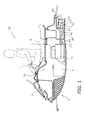
- FIG. 1 is a cross-sectional view of an entire structure of a jet propelled watercraft equipped with an engine according to a preferred embodiment of the present invention.
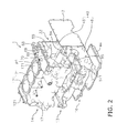
- FIG. 2 is an exploded view of an engine unit.
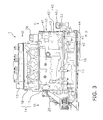
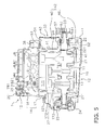
- FIG. 3 is a side view of the engine unit.
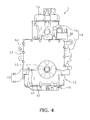
- FIG. 4 is a rear view of the engine unit.
- FIG. 5 is a cross-sectional side view of the engine unit.
- FIG. 6 is a schematic view of a lubrication system of the engine.
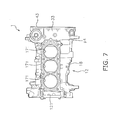
- FIG. 7 is a top view of a cylinder unit.
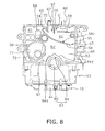
- FIG. 8 is a rear view of the interior of an oil tank.
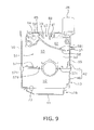
- FIG. 9 is a cross-sectional view of the engine unit taken along a cutaway line IX-IX in FIG. 3 .
- FIG. 1 is a cross-sectional view of an entire structure of a vehicle 100 equipped with an engine unit 1 according to a preferred embodiment of the present invention.
- vehicle 100 preferably is, for example, a jet propelled watercraft, such as a so-called personal watercraft (PWC).
- PWC personal watercraft
- the vehicle 100 includes the engine unit 1 and a vehicle body 2 .
- the vehicle body 2 includes a hull 4 and a jet propulsion unit 3 .
- the engine unit 1 and the jet propulsion unit 3 are installed in the hull 4 .
- the jet propulsion unit 3 is configured to be driven by the engine unit 1 .
- the hull 4 includes an engine compartment 4 a in the interior thereof.
- the engine compartment 4 a accommodates the engine unit 1 , a fuel tank 5 , and so forth.
- a seat 6 is attached to the hull 4 .
- the seat 6 is disposed over the engine unit 1 .
- the seat 6 is, for example, a saddle-ridding type seat.
- a steering member 7 is disposed in front of the seat 6 in order to steer the hull 4 . It should be noted that in the following explanation, directional terms “front”, “rear,” “right” and “left” and their related terms refer to directions as seen from a rider seated on the seat 6 in a position of the vehicle 100 floating in still water.
- the engine unit 1 includes a power transmission shaft 11 .
- the power transmission shaft 11 is disposed so as to extend in the back-and-forth direction.
- the jet propulsion unit 3 is configured to suck in water surrounding the hull 4 and eject the water.
- the jet propulsion unit 3 includes an impeller shaft 90 , an impeller 91 , an impeller housing 92 , a nozzle 93 , a deflector 94 , and a reverse gate 95 .
- the impeller shaft 90 is disposed so as to extend rearwardly from the engine compartment 4 a .
- the front portion of the impeller shaft 90 is connected to the power transmission shaft 11 .
- the rear portion of the impeller shaft 90 extends into the impeller housing 92 through a water suction portion 4 b of the hull 4 .
- the impeller housing 92 is connected to the rear portion of the water suction portion 4 b .
- the nozzle 93 is disposed behind the impeller housing 92 .
- the impeller 91 is attached to the rear portion of the impeller shaft 90 .
- the impeller 91 is disposed in the interior of the impeller housing 92 .
- the impeller 91 is configured to be rotated together with the impeller shaft 90 in order to suck in water from the water suction portion 4 b of the hull 4 .
- the impeller 91 is configured to cause the nozzle 93 to rearwardly eject the sucked in water.
- the deflector 94 is disposed behind the nozzle 93 .
- the deflector 94 is configured to switch the direction of water ejected from the nozzle 93 in the right-and-left direction.
- the reverse gate 95 is disposed behind the deflector 94 .
- the reverse gate 95 is configured to switch the direction of water ejected from the nozzle 93 and the deflector 94 toward the front of the vehicle 100 .
- the engine unit 1 includes the power transmission shaft 11 and an engine body 12 .
- the power transmission shaft 11 protrudes rearwardly from the engine body 12 .
- the power transmission shaft 11 is coupled to the impeller shaft 90 .
- FIG. 2 is an exploded view of the engine unit 1 .
- FIG. 3 is a side view of the engine unit 1 .
- FIG. 4 is a rear view of the engine unit 1 .
- FIG. 5 is a cross-sectional side view of the engine unit 1 .
- the engine body 12 includes a crankcase 13 , a cylinder unit 14 , a head cover 15 , and an oil pan 16 .
- the cylinder unit 14 is disposed over the crankcase 13 .
- the cylinder unit 14 includes a cylinder body 17 and a cylinder head 18 . It should be noted that the head cover 15 and the cylinder head 18 are not shown in FIG. 2 .
- the cylinder unit 14 is preferably a discrete element separate from the crankcase 13 .
- the cylinder body 17 and the cylinder head 18 are preferably discrete elements separate from each other. It should be noted that the cylinder body 17 and the cylinder head 18 may be an integral and unitary element.
- the crankcase 13 and the cylinder body 17 may be an integral and unitary element.
- the head cover 15 is disposed over the cylinder unit 14 .
- the oil pan 16 is disposed under the crankcase 13 .
- the oil pan 16 is preferably a discrete element separate from the crankcase 13 .
- the power transmission shaft 11 includes a crankshaft 21 , a coupling shaft 22 , and a coupling member 23 .
- the crankshaft 21 extends in the horizontal or substantially horizontal direction.
- the crankshaft 21 is accommodated in the crankcase 13 .
- the crankshaft 21 is preferably supported by the crankcase 13 and the cylinder body 17 . It should be noted that the crankshaft 21 may be supported only by the crankcase 13 .
- a power generator 24 is connected to the front end of the crankshaft 21 .
- a power generator cover 25 is attached to the engine body 12 .
- the power generator cover 25 is disposed in front of the engine body 12 .
- the power generator 24 is disposed inside the power generator cover 25 .
- the coupling shaft 22 is preferably a discrete element separate from the crankshaft 21 , and is coupled to the crankshaft 21 .
- the coupling shaft 22 is coupled to the rear end of the crankshaft 21 .
- the coupling member 23 is preferably a discrete element separate from the coupling shaft 22 , and is coupled to the coupling shaft 22 .
- the coupling member 23 is connected to the rear end of the coupling shaft 22 .
- the coupling member 23 of the power transmission shaft 11 is coupled to a coupling member 96 of the impeller shaft 90 .
- the cylinder body 17 includes a plurality of cylinders 171 preferably disposed in alignment in the back-and-forth direction.
- the axes of the respective cylinders 171 preferably extend in the up-and-down direction.
- Pistons 172 are disposed inside the cylinders 171 on a one-to-one basis. Each piston 172 is coupled to the crankshaft 21 through a connecting rod 173 .
- Combustion chambers 181 are provided inside the cylinder head 18 .
- Spark plugs 182 are attached to the cylinder head 18 .
- the engine unit 1 preferably is a three-stroke engine, for example. It should be noted that the number of the cylinders 171 is not limited to three, and alternatively, may be less than three or more than three.
- a camshaft 26 is disposed inside the cylinder head 18 and the head cover 15 .
- an intake valve and an exhaust valve (not shown in the drawings), mounted to each combustion chamber 181 , are configured to be opened and closed.
- a first sprocket 261 is attached to the front end of the cam shaft 26 .
- a second sprocket 211 is preferably press-fitted, for example, to the crankshaft 21 .
- a cam chain 27 is wrapped about the first sprocket 261 and the second sprocket 211 .
- the cam shaft 26 is configured to be driven when rotation of the crankshaft 21 is transmitted thereto through the cam chain 27 .
- the engine body 12 includes a cam chain compartment 121 .
- the cam chain 27 is disposed in the cam chain compartment 121 .
- the cam chain compartment 121 is disposed across the crankcase 13 and the cylinder unit 14 .
- the cam chain compartment 121 is disposed in front of the cylinders 171 .
- the cam chain compartment 121 is disposed between the power generator cover 25 and the cylinders 171 .
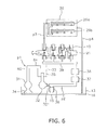
- FIG. 6 is a schematic diagram showing the lubrication system of the engine unit 1 .
- the engine unit 1 uses a dry sump as a lubrication method.
- the engine unit 1 includes a scavenging pump 31 , a feed pump 32 , and an oil tank 33 .
- the scavenging pump 31 is connected to a space defined by the oil pan 16 and the crankcase 13 through a strainer 34 . Further, the scavenging pump 31 is connected to the oil tank 33 through a first oil path p 1 .
- the feed pump 32 is connected to the oil tank 33 through a strainer 35 .
- the oil tank 33 will be explained below in detail.
- the feed pump 32 is connected to a second oil path p 2 through a check valve 321 .
- the check valve 321 allows the lubricating oil to flow from the oil tank 33 to the second oil path p 2 .
- the check valve 321 prevents the lubricating oil from reversely flowing from the second oil path p 2 to the oil tank 33 .
- a relief valve 36 is connected to the second oil path p 2 .
- the relief valve 36 is configured to be opened when the pressure of the lubricating oil within the feed pump 32 becomes a predetermined relief pressure or greater. When the relief valve 36 is opened, the lubricating oil within the feed pump 32 partially flows to the oil pan 16 .
- the second oil path p 2 is connected to a main gallery 39 through an oil cooler 37 and an oil cleaner 38 .
- the main gallery 39 is connected to oil paths inside the crankshaft 21 .
- the main gallery 39 is connected to a third oil path p 3 .
- the third oil path p 3 is connected to oil paths inside the cam shaft 26 .
- the cam shaft 26 includes an exhaust cam shaft 26 a and an intake cam shaft 26 b .
- the third oil path p 3 is connected to an oil path of the exhaust cam shaft 26 a and an oil path of the intake cam shaft 26 b.
- the oil paths inside the camshaft 26 are connected to a fourth oil path p 4 .
- the fourth oil path p 4 is connected to the oil path of the exhaust cam shaft 26 a and the oil path of the intake cam shaft 26 b .
- the fourth oil path p 4 is connected to the space inside the oil pan 16 .
- the fourth oil path p 4 will be explained below in detail.
- the lubricating oil is fed to the second oil path p 2 from the oil tank 33 by the feed pump 32 .
- the lubricating oil is further fed from the second oil path p 2 to the main gallery 39 through the oil cooler 37 and the oil cleaner 38 .
- the lubricating oil is partially supplied from the main gallery 39 to journals of the crankshaft 21 through the oil paths inside the crankshaft 21 . Further, the lubricating oil is supplied from the oil paths inside the crankshaft 21 to the pistons 172 (see FIG. 5 ) through piston coolers 40 .
- the lubricating oil is partially fed from the main gallery 39 to the oil paths inside the cam shaft 26 through the third oil path p 3 .
- the lubricating oil is supplied to journals of the cam shaft 26 through the oil paths inside the cam shaft 26 .
- the oil supplied to the respective elements disposed inside the engine body 12 as described above, flows through the interior of the cylinder head 18 or that of the crankcase 13 and returns to the oil pan 16 . Further, a surplus amount of lubricating oil inside the cam shaft 26 flows through the fourth oil path p 4 and returns to the oil pan 16 . The lubricating oil is returned from the oil pan 16 to the oil tank 33 by the scavenging pump 31 .
- FIG. 7 is a top view of the cylinder unit 14 .
- the oil tank 33 is preferably disposed behind the engine body 12 .
- the fourth oil path p 4 is preferably disposed in front of the oil tank 33 .
- the fourth oil path p 4 is preferably disposed behind the cylinders 171 .
- the fourth oil path p 4 is preferably disposed between the oil tank 33 and the cylinder unit 14 in the back-and-forth direction.
- the fourth oil path p 4 communicates with the space inside the head cover 15 , extends downwardly in the cylinder head 18 , and extends to the oil pan 16 via the cylinder body 17 .
- the fourth oil path p 4 is preferably at least partially integral and unitary with the oil tank 33 .
- the fourth oil path p 4 may be at least partially integral and unitary with the cylinder head 18 and the cylinder body 17 .
- the engine unit 1 includes a pump drive mechanism 41 .
- the pump drive mechanism 41 is configured to drive the scavenging pump 31 and the feed pump 32 in conjunction with rotation of the crankshaft 21 .
- the pump drive mechanism 41 is a chain, for example.
- the pump drive mechanism 41 is wrapped about the drive shaft of the scavenging pump 31 , the drive shaft of the feed pump 32 , and the power transmission shaft 11 .
- the pump drive mechanism 41 is wrapped about a sprocket 221 mounted to the coupling shaft 22 .
- Rotation of the power transmission shaft 11 is configured to be transmitted to the drive shaft of the scavenging pump 31 and the drive shaft of the feed pump 32 through the pump drive mechanism 41 .
- the scavenging pump 31 and the feed pump 32 are thus driven.
- the pump drive mechanism 41 is disposed in an intermediate portion of the fourth oil path p 4 .
- the pump drive mechanism 41 is lubricated by the lubricating oil flowing through the fourth oil path p 4 .
- the pump drive mechanism 41 is not limited to a chain, and alternatively, may be another member.
- the pump drive mechanism 41 may be a gear.
- the oil tank 33 preferably has a shape elongated in the up-and-down direction.
- the oil tank 33 is preferably integral and unitary with the engine body 12 .
- the fourth oil path p 4 is also preferably integral and unitary with the oil tank 33 .
- the fourth oil path p 4 is preferably integral and unitary with the engine body 12 and the oil tank 33 by being die cast together.
- This structure eliminates the necessity of separately providing other members such as a hose, and achieves a reduction in the number of components. Further, a large space is reliably provided in an area surrounding the engine unit 1 in comparison with a structure that other members such as a hose are separately provided and disposed in the space surrounding the engine unit 1 .
- the oil tank 33 includes a tank body 42 , a first component 43 , and a second component 44 .
- the tank body 42 includes a first body portion 45 and a second body portion 46 .
- the second body portion 46 is preferably a discrete element separate from the first body portion 45 .
- the first body portion 45 is preferably integrally molded with the cylinder unit 14 .
- the first body portion 45 is integrally molded with the cylinder body 17 .
- the first body portion 45 is located behind the cylinder unit 14 .
- the second body portion 46 is preferably integrally molded with the crankcase 13 .
- the second body portion 46 is located behind the crankcase 13 .
- the second body portion 46 is located under the first body portion 45 .
- the first component 43 is preferably a discrete element separate from the tank body 42 .
- the first component 43 preferably is a plate-shaped, i.e., flat, member.
- the first component 43 is joined to the tank body 42 .
- the first component 43 is joined to the rear surface of the first body portion 45 .
- the rear surface of the first body portion 45 opens horizontally.
- the first component 43 is joined to the first body portion 45 , and thus, covers the opening in the rear surface of the first body portion 45 .
- the bottom surface of the first body portion 45 opens downwardly.
- the top surface of the second body portion 46 opens upwardly.
- the cylinder unit 14 is joined to the crankcase 13 , and thus, the first body portion 45 is joined to the second body portion 46 .
- the second body portion 46 covers the opening in the bottom surface of the first body portion 45 .
- the first body portion 45 covers the top surface of the second body portion 46 .
- the second component 44 is preferably a discrete element separate from the tank body 42 .
- the second component 44 is preferably integrally molded with the oil pan 16 .
- the oil pan 16 is joined to the crankcase 13 , and thus, the second component 44 is joined to the tank body 42 .
- the second component 44 is joined to the bottom surface of the second body portion 46 .
- the bottom surface of the second body portion 46 opens downwardly.
- the second component 44 covers the opening in the bottom surface of the tank body 42 .
- a first joint surface s 1 between the tank body 42 and the first component 43 extends in a first direction different from that of a second direction in which the second joint surface s 2 extends between the tank body 42 and the second component 44 . Further, the first joint surface s 1 and the second joint surface s 2 are separated from each other.
- the first direction in which the first joint surface s 1 extends is vertical or substantially vertical.
- the second direction in which the second joint surface s 2 extends is horizontal or substantially horizontal. Therefore, the first direction in which the first joint surface s 1 extends is orthogonal or substantially orthogonal to the second direction in which the second joint surface s 2 extends.
- the first joint surface s 1 between the tank body 42 and the first component 43 extends in the first direction different from that of a third direction in which the third joint surface s 3 extends between the first body portion 45 and the second body portion 46 .
- the first joint surface s 1 is located over the third joint surface s 3 .
- the third direction in which the third joint surface s 3 extends is horizontal or substantially horizontal. Therefore, the first direction of the first joint surface s 1 is orthogonal or substantially orthogonal to the third direction in which the third joint surface s 3 extends.
- the oil tank 33 includes an upper oil chamber 51 and a lower oil chamber 52 .
- the upper oil chamber 51 is inside the first body portion 45 .
- the lower oil chamber 52 is inside the second body portion 46 .
- FIG. 8 is a rear view of the engine unit 1 in a condition that the first component 43 is detached therefrom.
- the first body portion 45 includes a partition wall 53 , a top wall 54 , a first sidewall 55 , a second sidewall 56 , and a bottom wall 57 .
- the partition wall 53 divides the upper oil chamber 51 and the space inside the cylinder unit 14 .
- the top wall 54 , the first sidewall 55 , the second sidewall 56 , and the bottom wall 57 extend rearwardly from the partition wall 53 .
- FIG. 9 is a cross-sectional view of FIG. 3 taken along a cutaway line IX-IX. As shown in FIG. 9 , the bottom wall 57 includes a plurality of apertures 571 penetrating therethrough in the up-and-down direction. The upper oil chamber 51 and the lower oil chamber 52 communicate with each other through these apertures 571 .
- the first body portion 45 includes a guide plate 58 extending horizontally or substantially horizontally in the interior thereof.
- the guide plate 58 extends in the back-and-forth direction.
- the guide plate 58 extends rearwardly from the partition wall 53 .
- the guide plate 58 divides the upper oil chamber 51 into a first chamber 61 , a second chamber 62 , and a third chamber 63 .
- the first body portion 45 includes a portion 64 (hereinafter referred to as a first pump connection path 64 ) of the first oil path p 1 .
- the first pump connection path 64 is connected to the first chamber 61 .
- the first oil path p 1 further includes a path 60 .
- the path 60 extends in the up-and-down direction.
- the first pump connection path 64 is connected to the scavenging pump 31 through the path 60 .
- the first pump connection path 64 extends in the back-and-forth direction.
- the second chamber 62 is located laterally of the first chamber 61 .
- the second chamber 62 communicates with the first chamber 61 through a communication path 65 .
- the width of the communication path 65 is preferably narrower than the up-and-down directional width of the first chamber 61 .
- the guide plate 58 includes a tilt portion 581 .
- the tilt portion 581 divides the second chamber 62 and the third chamber 63 .
- the tilt portion 581 is located under the second chamber 62 .
- the tilt portion 581 tilts downwardly to a lateral side.
- the first body portion 45 includes a first connection port 66 and a second connection port 67 .
- the first connection port 66 and the second connection port 67 communicate with the upper oil chamber 51 .
- the first connection port 66 is connected to a separator (not shown in the drawings).
- the second connection port 67 is connected to the head cover 15 .
- the first connection port 66 and the second connection port 67 are located over the second chamber 62 .
- the first connection port 66 and the second connection port 67 are aligned in the right-and-left direction.
- the first body portion 45 includes a first partition 68 , a second partition 69 , and a third partition 70 .
- the first partition 68 divides the second chamber 62 and the first connection port 66 .
- the second partition 69 divides the first connection port 66 and the second connection port 67 .
- the third partition 70 divides the second connection port 67 and the communication path 65 .
- the second chamber 62 and the space in which the first connection port 66 is disposed communicate through a first gap g 1 .
- the second chamber 62 and the space in which the second connection port 67 is disposed communicate through a second gap g 2 .
- the third chamber 63 is located under the first chamber 61 and the second chamber 62 .
- the third chamber 63 communicates with the second chamber 62 through a third gap g 3 .
- the first body portion 45 includes an opening 71 .
- the opening 71 is provided in the third chamber 63 .
- the opening 71 extends in the back-and-forth direction and communicates with the interior of the crankcase 13 .
- the opening 71 is closed by a lid member 72 .
- the bottom wall 57 is disposed under the third chamber 63 .
- the third chamber 63 communicates with the lower oil chamber 52 through the plurality of apertures 571 of the bottom wall 57 .
- the bottom wall 57 functions as a baffle plate to lessen and stabilize the momentum of the lubricating oil flowing from the third chamber 63 to the lower oil chamber 52 .
- the second body portion 46 includes a second pump connection path 73 .
- the second pump connection path 73 is disposed across the second body portion 46 and the second component 44 .
- the second pump connection path 73 is connected to the lower oil chamber 52 .
- the strainer 35 is disposed inside the second pump connection path 73 and is connected to the feed pump 32 .
- the second pump connection path 73 extends in the back-and-forth direction.
- the lubricating oil existing inside the oil pan 16 , is fed to the first oil path p 1 by the scavenging pump 31 .
- the lubricating oil is fed to the first chamber 61 through the first pump connection path 64 .
- the lubricating oil is fed from the first chamber 61 to the second chamber 62 through the communication path 65 .
- the lubricating oil flows along the tilt portion 581 in the second chamber 62 and is fed to the third chamber 63 .
- the lubricating oil is fed from the third chamber 63 to the lower oil chamber 52 through the apertures 571 of the bottom wall 57 .
- the lubricating oil is sucked from the lower oil chamber 52 into the feed pump 32 through the second pump connection path 73 and is fed to the second oil path p 2 by the feed pump 32 .
- the oil tank 33 supports the power transmission shaft 11 through bearings 81 and 82 .
- the power transmission shaft 11 at least partially overlaps with the oil tank 33 in a side view.
- the power transmission shaft 11 extends rearwardly from the engine body 12 to a position beyond the oil tank 33 .
- the coupling shaft 22 overlaps with the oil tank 33 in the side view. Further, the coupling shaft 22 is supported by the oil tank 33 through the bearings 81 and 82 . The coupling shaft 22 extends rearwardly from the engine body 12 to a position beyond the oil tank 33 .
- the oil tank 33 includes a through hole 83 extending in the axial direction of the power transmission shaft 11 .
- the power transmission shaft 11 is disposed inside the through hole 83 .
- the coupling shaft 22 is disposed inside the through hole 83 .
- the oil tank 33 has a shape configured to avoid contact with the power transmission shaft 11 .
- a structure of the oil tank 33 surrounding the power transmission shaft 11 will be hereinafter explained.
- the upper oil chamber 51 is located over the power transmission shaft 11 .
- the lower oil chamber 52 is located under the power transmission shaft 11 .
- the power transmission shaft 11 is partially disposed between the upper oil chamber 51 and the lower oil chamber 52 .
- the power transmission shaft 11 is supported by the bottom surface of the upper oil chamber 51 and the top surface of the lower oil chamber 52 .
- the power transmission shaft 11 is supported by the bottom surface of the upper oil chamber 51 and the top surface of the lower oil chamber 52 through the bearings 81 and 82 .
- the bottom wall 57 includes an upper recess 84 having an upwardly recessed shape.
- the upper recess 84 includes slopes 841 and 842 that correspond to the shape of the power transmission shaft 11 .
- the upper recess 84 preferably has a circular or substantially circular-arc shape that corresponds to the shape of the power transmission shaft 11 .
- the space inside the upper recess 84 is separate from the upper oil chamber 51 .
- the upper surface of the second body portion 46 includes a lower recess 85 having a downwardly recessed shape.
- the lower recess 85 preferably has a circular or substantially circular-arc shape that corresponds to the shape of the power transmission shaft 11 .
- the space inside the lower recess 85 is separate from the lower oil chamber 52 .
- the power transmission shaft 11 is disposed between the upper recess 84 and the lower recess 85 .
- the through hole 83 is defined by the upper recess 84 and the lower recess 85 .
- the power transmission shaft 11 partially overlaps with the oil tank 33 in the side view.
- the power transmission shaft 11 extends from the engine body 12 to the position beyond the oil tank 33 in the axial direction of the crankshaft 21 . Therefore, even when the oil tank 33 is enlarged in the axial direction of the crankshaft 21 , the engine unit 1 still has a small size.
- the vehicle 100 is preferably a jet propelled watercraft.
- the vehicle according to the preferred embodiments of the present invention is not limited to a jet propelled watercraft.
- the vehicle according to the preferred embodiments of the present invention is not limited to a water vehicle, and may be another type of vehicle such as an ATV (All Terrain Vehicle), a snowmobile, or a motorcycle.
- the jet propelled watercraft is not limited to the PWC as described in the preferred embodiments above, and may be another type of water vehicle such as a sport boat.
- the orientation of the engine unit 1 is not limited to that described in the above preferred embodiments.
- the orientation of the engine unit 1 may be reversed in the back-and-forth direction from that described in the above preferred embodiments.
- the engine unit 1 may be disposed such that the axis of the crankshaft 21 is oriented in the right-and-left direction of the vehicle.
- the term “lateral” does not necessarily mean a direction matched with the right-and-left direction of the vehicle including the engine unit. In the engine unit according a preferred embodiment of the present invention, the term “lateral” may mean any direction in the horizontal direction.
- the structure or the positional arrangement of the oil tank 33 is not limited to that described in the above preferred embodiments, and may be changed.
- the oil tank 33 may be a discrete element separate from the engine body 12 .
- the oil tank 33 may not be divided into the tank body 42 , the first component 43 , and the second component 44 .
- the tank body 42 may not be divided into the first body portion 45 and the second body portion 46 .
- the second component 44 may be a discrete element separate from the oil pan 16 .
- the oil tank 33 includes the through hole 83 .
- the oil tank 33 may have a recessed shape so as to avoid contact with the power transmission shaft 11 .
- the bottom surface of the oil tank 33 may have an upwardly recessed shape so as to avoid contact with the power transmission shaft 11 .
- the top surface of the oil tank 33 may have a downwardly recessed shape so as to avoid contact with the power transmission shaft 11 .
- the lateral surface of the oil tank 33 may have a laterally recessed shape so as to avoid contact with the power transmission shaft 11 .
Landscapes
- Engineering & Computer Science (AREA)
- General Engineering & Computer Science (AREA)
- Mechanical Engineering (AREA)
- Chemical & Material Sciences (AREA)
- Combustion & Propulsion (AREA)
- Ocean & Marine Engineering (AREA)
- Lubrication Of Internal Combustion Engines (AREA)
- Lubrication Details And Ventilation Of Internal Combustion Engines (AREA)
Abstract
Description
- 1. Field of the Invention
- The present invention relates to an engine unit for a vehicle.
- 2. Description of the Related Art
- An engine unit includes an oil tank configured to store lubricating oil of an engine. For example, the oil tank is disposed on an imaginary line extending from a crankshaft of the engine in the structure described in Japan Laid-open Patent Application Publication No. JP-A-2003-27911.
- When the oil tank is disposed on the imaginary line extending from the crankshaft as described above, there is a drawback that the engine unit is enlarged in the axial direction of the crankshaft by a space from the tip of the crankshaft to the outer surface of the oil tank. Especially, the engine unit is inevitably further enlarged when the oil tank is enlarged in the axial direction of the crankshaft so as to increase the capacity thereof.
- Preferred embodiments of the present invention reliably provide an oil tank with a large capacity and an engine unit with a small size.
- An engine unit for a vehicle according to a preferred embodiment of the present invention includes an engine body, an oil tank, and a power transmission shaft. The engine body includes a cylinder unit and a crankcase. The oil tank is disposed horizontally with respect to the engine body. The power transmission shaft includes a crankshaft supported by the crankcase. The power transmission shaft at least partially overlaps with the oil tank in a side view of the engine unit. The power transmission shaft extends from the engine body to a position beyond the oil tank in an axial direction of the crankshaft.
- In the engine unit for a vehicle according to a preferred embodiment of the present invention, the power transmission shaft at least partially overlaps with the oil tank in the side view. However, the power transmission shaft extends from the engine body to the position beyond the oil tank in the axial direction of the crankshaft. Thus, even when the oil tank is enlarged in the axial direction of the crankshaft, the engine unit has a small size.
- The above and other elements, features, steps, characteristics and advantages of the present invention will become more apparent from the following detailed description of the preferred embodiments with reference to the attached drawings.
-
FIG. 1 is a cross-sectional view of an entire structure of a jet propelled watercraft equipped with an engine according to a preferred embodiment of the present invention. -
FIG. 2 is an exploded view of an engine unit. -
FIG. 3 is a side view of the engine unit. -
FIG. 4 is a rear view of the engine unit. -
FIG. 5 is a cross-sectional side view of the engine unit. -
FIG. 6 is a schematic view of a lubrication system of the engine. -
FIG. 7 is a top view of a cylinder unit. -
FIG. 8 is a rear view of the interior of an oil tank. -
FIG. 9 is a cross-sectional view of the engine unit taken along a cutaway line IX-IX inFIG. 3 . - Preferred embodiments of the present invention will be hereinafter explained with reference to the attached drawings.
FIG. 1 is a cross-sectional view of an entire structure of avehicle 100 equipped with anengine unit 1 according to a preferred embodiment of the present invention. Thevehicle 100 preferably is, for example, a jet propelled watercraft, such as a so-called personal watercraft (PWC). - The
vehicle 100 includes theengine unit 1 and avehicle body 2. Thevehicle body 2 includes ahull 4 and ajet propulsion unit 3. Theengine unit 1 and thejet propulsion unit 3 are installed in thehull 4. Thejet propulsion unit 3 is configured to be driven by theengine unit 1. - The
hull 4 includes anengine compartment 4 a in the interior thereof. Theengine compartment 4 a accommodates theengine unit 1, afuel tank 5, and so forth. Aseat 6 is attached to thehull 4. Theseat 6 is disposed over theengine unit 1. Theseat 6 is, for example, a saddle-ridding type seat. Asteering member 7 is disposed in front of theseat 6 in order to steer thehull 4. It should be noted that in the following explanation, directional terms “front”, “rear,” “right” and “left” and their related terms refer to directions as seen from a rider seated on theseat 6 in a position of thevehicle 100 floating in still water. - The
engine unit 1 includes apower transmission shaft 11. Thepower transmission shaft 11 is disposed so as to extend in the back-and-forth direction. Thejet propulsion unit 3 is configured to suck in water surrounding thehull 4 and eject the water. Thejet propulsion unit 3 includes animpeller shaft 90, animpeller 91, animpeller housing 92, anozzle 93, adeflector 94, and areverse gate 95. Theimpeller shaft 90 is disposed so as to extend rearwardly from theengine compartment 4 a. The front portion of theimpeller shaft 90 is connected to thepower transmission shaft 11. The rear portion of theimpeller shaft 90 extends into theimpeller housing 92 through awater suction portion 4 b of thehull 4. Theimpeller housing 92 is connected to the rear portion of thewater suction portion 4 b. Thenozzle 93 is disposed behind theimpeller housing 92. - The
impeller 91 is attached to the rear portion of theimpeller shaft 90. Theimpeller 91 is disposed in the interior of theimpeller housing 92. Theimpeller 91 is configured to be rotated together with theimpeller shaft 90 in order to suck in water from thewater suction portion 4 b of thehull 4. Theimpeller 91 is configured to cause thenozzle 93 to rearwardly eject the sucked in water. Thedeflector 94 is disposed behind thenozzle 93. Thedeflector 94 is configured to switch the direction of water ejected from thenozzle 93 in the right-and-left direction. Thereverse gate 95 is disposed behind thedeflector 94. Thereverse gate 95 is configured to switch the direction of water ejected from thenozzle 93 and thedeflector 94 toward the front of thevehicle 100. - The
engine unit 1 includes thepower transmission shaft 11 and anengine body 12. Thepower transmission shaft 11 protrudes rearwardly from theengine body 12. Thepower transmission shaft 11 is coupled to theimpeller shaft 90. -
FIG. 2 is an exploded view of theengine unit 1.FIG. 3 is a side view of theengine unit 1.FIG. 4 is a rear view of theengine unit 1.FIG. 5 is a cross-sectional side view of theengine unit 1. As shown inFIGS. 2 to 5 , theengine body 12 includes acrankcase 13, acylinder unit 14, ahead cover 15, and anoil pan 16. - The
cylinder unit 14 is disposed over thecrankcase 13. Thecylinder unit 14 includes acylinder body 17 and acylinder head 18. It should be noted that thehead cover 15 and thecylinder head 18 are not shown inFIG. 2 . Thecylinder unit 14 is preferably a discrete element separate from thecrankcase 13. Thecylinder body 17 and thecylinder head 18 are preferably discrete elements separate from each other. It should be noted that thecylinder body 17 and thecylinder head 18 may be an integral and unitary element. Thecrankcase 13 and thecylinder body 17 may be an integral and unitary element. Thehead cover 15 is disposed over thecylinder unit 14. Theoil pan 16 is disposed under thecrankcase 13. Theoil pan 16 is preferably a discrete element separate from thecrankcase 13. - As shown in
FIG. 5 , thepower transmission shaft 11 includes acrankshaft 21, acoupling shaft 22, and acoupling member 23. Thecrankshaft 21 extends in the horizontal or substantially horizontal direction. Thecrankshaft 21 is accommodated in thecrankcase 13. Thecrankshaft 21 is preferably supported by thecrankcase 13 and thecylinder body 17. It should be noted that thecrankshaft 21 may be supported only by thecrankcase 13. Apower generator 24 is connected to the front end of thecrankshaft 21. Apower generator cover 25 is attached to theengine body 12. Thepower generator cover 25 is disposed in front of theengine body 12. Thepower generator 24 is disposed inside thepower generator cover 25. - The
coupling shaft 22 is preferably a discrete element separate from thecrankshaft 21, and is coupled to thecrankshaft 21. When described in detail, thecoupling shaft 22 is coupled to the rear end of thecrankshaft 21. Thecoupling member 23 is preferably a discrete element separate from thecoupling shaft 22, and is coupled to thecoupling shaft 22. When described in detail, thecoupling member 23 is connected to the rear end of thecoupling shaft 22. As shown inFIG. 1 , thecoupling member 23 of thepower transmission shaft 11 is coupled to acoupling member 96 of theimpeller shaft 90. - The
cylinder body 17 includes a plurality ofcylinders 171 preferably disposed in alignment in the back-and-forth direction. The axes of therespective cylinders 171 preferably extend in the up-and-down direction.Pistons 172 are disposed inside thecylinders 171 on a one-to-one basis. Eachpiston 172 is coupled to thecrankshaft 21 through a connectingrod 173.Combustion chambers 181 are provided inside thecylinder head 18. Spark plugs 182 are attached to thecylinder head 18. - It should be noted that in
FIG. 5 , reference numerals are assigned to only one of thecylinders 171, one of thepistons 172, and one of the connectingrods 173, and thus are not assigned to theother cylinders 171, theother pistons 172, and the other connectingrods 173. In the present preferred embodiment, theengine unit 1 preferably is a three-stroke engine, for example. It should be noted that the number of thecylinders 171 is not limited to three, and alternatively, may be less than three or more than three. - A
camshaft 26 is disposed inside thecylinder head 18 and thehead cover 15. When thecam shaft 26 is driven, an intake valve and an exhaust valve (not shown in the drawings), mounted to eachcombustion chamber 181, are configured to be opened and closed. Afirst sprocket 261 is attached to the front end of thecam shaft 26. Asecond sprocket 211 is preferably press-fitted, for example, to thecrankshaft 21. Acam chain 27 is wrapped about thefirst sprocket 261 and thesecond sprocket 211. Thecam shaft 26 is configured to be driven when rotation of thecrankshaft 21 is transmitted thereto through thecam chain 27. - The
engine body 12 includes acam chain compartment 121. Thecam chain 27 is disposed in thecam chain compartment 121. Thecam chain compartment 121 is disposed across thecrankcase 13 and thecylinder unit 14. Thecam chain compartment 121 is disposed in front of thecylinders 171. Thecam chain compartment 121 is disposed between thepower generator cover 25 and thecylinders 171. - Next, a lubrication system of the
engine unit 1 will be explained.FIG. 6 is a schematic diagram showing the lubrication system of theengine unit 1. Theengine unit 1 uses a dry sump as a lubrication method. As shown inFIG. 6 , theengine unit 1 includes a scavengingpump 31, afeed pump 32, and anoil tank 33. The scavengingpump 31 is connected to a space defined by theoil pan 16 and thecrankcase 13 through astrainer 34. Further, the scavengingpump 31 is connected to theoil tank 33 through a first oil path p1. Thefeed pump 32 is connected to theoil tank 33 through astrainer 35. Theoil tank 33 will be explained below in detail. - The
feed pump 32 is connected to a second oil path p2 through acheck valve 321. Thecheck valve 321 allows the lubricating oil to flow from theoil tank 33 to the second oil path p2. Thecheck valve 321 prevents the lubricating oil from reversely flowing from the second oil path p2 to theoil tank 33. Further, arelief valve 36 is connected to the second oil path p2. Therelief valve 36 is configured to be opened when the pressure of the lubricating oil within thefeed pump 32 becomes a predetermined relief pressure or greater. When therelief valve 36 is opened, the lubricating oil within thefeed pump 32 partially flows to theoil pan 16. - The second oil path p2 is connected to a
main gallery 39 through anoil cooler 37 and anoil cleaner 38. Themain gallery 39 is connected to oil paths inside thecrankshaft 21. Further, themain gallery 39 is connected to a third oil path p3. The third oil path p3 is connected to oil paths inside thecam shaft 26. It should be noted that thecam shaft 26 includes anexhaust cam shaft 26 a and anintake cam shaft 26 b. The third oil path p3 is connected to an oil path of theexhaust cam shaft 26 a and an oil path of theintake cam shaft 26 b. - The oil paths inside the
camshaft 26 are connected to a fourth oil path p4. The fourth oil path p4 is connected to the oil path of theexhaust cam shaft 26 a and the oil path of theintake cam shaft 26 b. The fourth oil path p4 is connected to the space inside theoil pan 16. The fourth oil path p4 will be explained below in detail. - In the
engine unit 1 according to the present preferred embodiment, the lubricating oil is fed to the second oil path p2 from theoil tank 33 by thefeed pump 32. The lubricating oil is further fed from the second oil path p2 to themain gallery 39 through theoil cooler 37 and theoil cleaner 38. - The lubricating oil is partially supplied from the
main gallery 39 to journals of thecrankshaft 21 through the oil paths inside thecrankshaft 21. Further, the lubricating oil is supplied from the oil paths inside thecrankshaft 21 to the pistons 172 (seeFIG. 5 ) throughpiston coolers 40. - The lubricating oil is partially fed from the
main gallery 39 to the oil paths inside thecam shaft 26 through the third oil path p3. The lubricating oil is supplied to journals of thecam shaft 26 through the oil paths inside thecam shaft 26. - The oil, supplied to the respective elements disposed inside the
engine body 12 as described above, flows through the interior of thecylinder head 18 or that of thecrankcase 13 and returns to theoil pan 16. Further, a surplus amount of lubricating oil inside thecam shaft 26 flows through the fourth oil path p4 and returns to theoil pan 16. The lubricating oil is returned from theoil pan 16 to theoil tank 33 by the scavengingpump 31. -
FIG. 7 is a top view of thecylinder unit 14. As shown inFIGS. 5 and 7 , theoil tank 33 is preferably disposed behind theengine body 12. When described in detail, theoil tank 33 is disposed behind thecrankcase 13 and thecylinder body 17. The fourth oil path p4 is preferably disposed in front of theoil tank 33. The fourth oil path p4 is preferably disposed behind thecylinders 171. The fourth oil path p4 is preferably disposed between theoil tank 33 and thecylinder unit 14 in the back-and-forth direction. The fourth oil path p4 communicates with the space inside thehead cover 15, extends downwardly in thecylinder head 18, and extends to theoil pan 16 via thecylinder body 17. The fourth oil path p4 is preferably at least partially integral and unitary with theoil tank 33. The fourth oil path p4 may be at least partially integral and unitary with thecylinder head 18 and thecylinder body 17. - As shown in
FIG. 5 , theengine unit 1 includes apump drive mechanism 41. Thepump drive mechanism 41 is configured to drive the scavengingpump 31 and thefeed pump 32 in conjunction with rotation of thecrankshaft 21. In the present preferred embodiment, thepump drive mechanism 41 is a chain, for example. Thepump drive mechanism 41 is wrapped about the drive shaft of the scavengingpump 31, the drive shaft of thefeed pump 32, and thepower transmission shaft 11. When described in detail, thepump drive mechanism 41 is wrapped about asprocket 221 mounted to thecoupling shaft 22. Rotation of thepower transmission shaft 11 is configured to be transmitted to the drive shaft of the scavengingpump 31 and the drive shaft of thefeed pump 32 through thepump drive mechanism 41. The scavengingpump 31 and thefeed pump 32 are thus driven. - The
pump drive mechanism 41 is disposed in an intermediate portion of the fourth oil path p4. Thus, thepump drive mechanism 41 is lubricated by the lubricating oil flowing through the fourth oil path p4. It should be noted that thepump drive mechanism 41 is not limited to a chain, and alternatively, may be another member. For example, thepump drive mechanism 41 may be a gear. - Next, a structure of the
oil tank 33 will be explained in detail. As shown inFIG. 5 , theoil tank 33 preferably has a shape elongated in the up-and-down direction. Theoil tank 33 is preferably integral and unitary with theengine body 12. The fourth oil path p4 is also preferably integral and unitary with theoil tank 33. The fourth oil path p4 is preferably integral and unitary with theengine body 12 and theoil tank 33 by being die cast together. This structure eliminates the necessity of separately providing other members such as a hose, and achieves a reduction in the number of components. Further, a large space is reliably provided in an area surrounding theengine unit 1 in comparison with a structure that other members such as a hose are separately provided and disposed in the space surrounding theengine unit 1. - As shown in
FIG. 2 , theoil tank 33 includes atank body 42, afirst component 43, and asecond component 44. Thetank body 42 includes afirst body portion 45 and asecond body portion 46. Thesecond body portion 46 is preferably a discrete element separate from thefirst body portion 45. Thefirst body portion 45 is preferably integrally molded with thecylinder unit 14. When described in detail, thefirst body portion 45 is integrally molded with thecylinder body 17. Thefirst body portion 45 is located behind thecylinder unit 14. Thesecond body portion 46 is preferably integrally molded with thecrankcase 13. Thesecond body portion 46 is located behind thecrankcase 13. Thesecond body portion 46 is located under thefirst body portion 45. - The
first component 43 is preferably a discrete element separate from thetank body 42. Thefirst component 43 preferably is a plate-shaped, i.e., flat, member. Thefirst component 43 is joined to thetank body 42. When described in detail, thefirst component 43 is joined to the rear surface of thefirst body portion 45. The rear surface of thefirst body portion 45 opens horizontally. Thefirst component 43 is joined to thefirst body portion 45, and thus, covers the opening in the rear surface of thefirst body portion 45. - The bottom surface of the
first body portion 45 opens downwardly. The top surface of thesecond body portion 46 opens upwardly. Thecylinder unit 14 is joined to thecrankcase 13, and thus, thefirst body portion 45 is joined to thesecond body portion 46. With this structure, thesecond body portion 46 covers the opening in the bottom surface of thefirst body portion 45. In turn, thefirst body portion 45 covers the top surface of thesecond body portion 46. - The
second component 44 is preferably a discrete element separate from thetank body 42. Thesecond component 44 is preferably integrally molded with theoil pan 16. Theoil pan 16 is joined to thecrankcase 13, and thus, thesecond component 44 is joined to thetank body 42. When described in detail, thesecond component 44 is joined to the bottom surface of thesecond body portion 46. The bottom surface of thesecond body portion 46 opens downwardly. Thesecond component 44 covers the opening in the bottom surface of thetank body 42. - As shown in
FIG. 3 , a first joint surface s1 between thetank body 42 and thefirst component 43 extends in a first direction different from that of a second direction in which the second joint surface s2 extends between thetank body 42 and thesecond component 44. Further, the first joint surface s1 and the second joint surface s2 are separated from each other. When described in detail, the first direction in which the first joint surface s1 extends is vertical or substantially vertical. By contrast, the second direction in which the second joint surface s2 extends is horizontal or substantially horizontal. Therefore, the first direction in which the first joint surface s1 extends is orthogonal or substantially orthogonal to the second direction in which the second joint surface s2 extends. - The first joint surface s1 between the
tank body 42 and thefirst component 43 extends in the first direction different from that of a third direction in which the third joint surface s3 extends between thefirst body portion 45 and thesecond body portion 46. The first joint surface s1 is located over the third joint surface s3. When described in detail, the third direction in which the third joint surface s3 extends is horizontal or substantially horizontal. Therefore, the first direction of the first joint surface s1 is orthogonal or substantially orthogonal to the third direction in which the third joint surface s3 extends. - As shown in
FIG. 5 , theoil tank 33 includes anupper oil chamber 51 and alower oil chamber 52. Theupper oil chamber 51 is inside thefirst body portion 45. Thelower oil chamber 52 is inside thesecond body portion 46. -
FIG. 8 is a rear view of theengine unit 1 in a condition that thefirst component 43 is detached therefrom. Thefirst body portion 45 includes apartition wall 53, atop wall 54, afirst sidewall 55, asecond sidewall 56, and abottom wall 57. As shown inFIG. 5 , thepartition wall 53 divides theupper oil chamber 51 and the space inside thecylinder unit 14. Thetop wall 54, thefirst sidewall 55, thesecond sidewall 56, and thebottom wall 57 extend rearwardly from thepartition wall 53. - The
bottom wall 57 is disposed between theupper oil chamber 51 and thelower oil chamber 52. Thebottom wall 57 divides theupper oil chamber 51 and thelower oil chamber 52.FIG. 9 is a cross-sectional view ofFIG. 3 taken along a cutaway line IX-IX. As shown inFIG. 9 , thebottom wall 57 includes a plurality ofapertures 571 penetrating therethrough in the up-and-down direction. Theupper oil chamber 51 and thelower oil chamber 52 communicate with each other through theseapertures 571. - As shown in
FIG. 8 , thefirst body portion 45 includes aguide plate 58 extending horizontally or substantially horizontally in the interior thereof. When described in detail, theguide plate 58 extends in the back-and-forth direction. Theguide plate 58 extends rearwardly from thepartition wall 53. Theguide plate 58 divides theupper oil chamber 51 into afirst chamber 61, asecond chamber 62, and athird chamber 63. - The
first body portion 45 includes a portion 64 (hereinafter referred to as a first pump connection path 64) of the first oil path p1. The firstpump connection path 64 is connected to thefirst chamber 61. It should be noted that as shown inFIG. 6 , the first oil path p1 further includes apath 60. Thepath 60 extends in the up-and-down direction. The firstpump connection path 64 is connected to the scavengingpump 31 through thepath 60. The firstpump connection path 64 extends in the back-and-forth direction. - The
second chamber 62 is located laterally of thefirst chamber 61. Thesecond chamber 62 communicates with thefirst chamber 61 through acommunication path 65. The width of thecommunication path 65 is preferably narrower than the up-and-down directional width of thefirst chamber 61. Theguide plate 58 includes atilt portion 581. Thetilt portion 581 divides thesecond chamber 62 and thethird chamber 63. Thetilt portion 581 is located under thesecond chamber 62. Thetilt portion 581 tilts downwardly to a lateral side. - The
first body portion 45 includes afirst connection port 66 and asecond connection port 67. Thefirst connection port 66 and thesecond connection port 67 communicate with theupper oil chamber 51. Thefirst connection port 66 is connected to a separator (not shown in the drawings). Thesecond connection port 67 is connected to thehead cover 15. Thefirst connection port 66 and thesecond connection port 67 are located over thesecond chamber 62. Thefirst connection port 66 and thesecond connection port 67 are aligned in the right-and-left direction. - The
first body portion 45 includes afirst partition 68, asecond partition 69, and athird partition 70. Thefirst partition 68 divides thesecond chamber 62 and thefirst connection port 66. Thesecond partition 69 divides thefirst connection port 66 and thesecond connection port 67. Thethird partition 70 divides thesecond connection port 67 and thecommunication path 65. Thesecond chamber 62 and the space in which thefirst connection port 66 is disposed communicate through a first gap g1. Thesecond chamber 62 and the space in which thesecond connection port 67 is disposed communicate through a second gap g2. - The
third chamber 63 is located under thefirst chamber 61 and thesecond chamber 62. Thethird chamber 63 communicates with thesecond chamber 62 through a third gap g3. Thefirst body portion 45 includes anopening 71. Theopening 71 is provided in thethird chamber 63. Theopening 71 extends in the back-and-forth direction and communicates with the interior of thecrankcase 13. Theopening 71 is closed by alid member 72. Thebottom wall 57 is disposed under thethird chamber 63. As shown inFIG. 9 , thethird chamber 63 communicates with thelower oil chamber 52 through the plurality ofapertures 571 of thebottom wall 57. Thebottom wall 57 functions as a baffle plate to lessen and stabilize the momentum of the lubricating oil flowing from thethird chamber 63 to thelower oil chamber 52. - As shown in
FIG. 9 , thesecond body portion 46 includes a secondpump connection path 73. When described in detail, the secondpump connection path 73 is disposed across thesecond body portion 46 and thesecond component 44. The secondpump connection path 73 is connected to thelower oil chamber 52. Thestrainer 35 is disposed inside the secondpump connection path 73 and is connected to thefeed pump 32. The secondpump connection path 73 extends in the back-and-forth direction. - The lubricating oil, existing inside the
oil pan 16, is fed to the first oil path p1 by the scavengingpump 31. The lubricating oil is fed to thefirst chamber 61 through the firstpump connection path 64. The lubricating oil is fed from thefirst chamber 61 to thesecond chamber 62 through thecommunication path 65. The lubricating oil flows along thetilt portion 581 in thesecond chamber 62 and is fed to thethird chamber 63. The lubricating oil is fed from thethird chamber 63 to thelower oil chamber 52 through theapertures 571 of thebottom wall 57. The lubricating oil is sucked from thelower oil chamber 52 into thefeed pump 32 through the secondpump connection path 73 and is fed to the second oil path p2 by thefeed pump 32. - As shown in
FIG. 5 , theoil tank 33 supports thepower transmission shaft 11 throughbearings power transmission shaft 11 at least partially overlaps with theoil tank 33 in a side view. Thepower transmission shaft 11 extends rearwardly from theengine body 12 to a position beyond theoil tank 33. - When described in detail, the
coupling shaft 22 overlaps with theoil tank 33 in the side view. Further, thecoupling shaft 22 is supported by theoil tank 33 through thebearings coupling shaft 22 extends rearwardly from theengine body 12 to a position beyond theoil tank 33. - As shown in
FIG. 8 , theoil tank 33 includes a throughhole 83 extending in the axial direction of thepower transmission shaft 11. Thepower transmission shaft 11 is disposed inside the throughhole 83. When described in detail, thecoupling shaft 22 is disposed inside the throughhole 83. Thus, theoil tank 33 has a shape configured to avoid contact with thepower transmission shaft 11. A structure of theoil tank 33 surrounding thepower transmission shaft 11 will be hereinafter explained. - The
upper oil chamber 51 is located over thepower transmission shaft 11. Thelower oil chamber 52 is located under thepower transmission shaft 11. Thepower transmission shaft 11 is partially disposed between theupper oil chamber 51 and thelower oil chamber 52. Thepower transmission shaft 11 is supported by the bottom surface of theupper oil chamber 51 and the top surface of thelower oil chamber 52. Thepower transmission shaft 11 is supported by the bottom surface of theupper oil chamber 51 and the top surface of thelower oil chamber 52 through thebearings - The
bottom wall 57 includes anupper recess 84 having an upwardly recessed shape. Theupper recess 84 includesslopes power transmission shaft 11. When described in detail, theupper recess 84 preferably has a circular or substantially circular-arc shape that corresponds to the shape of thepower transmission shaft 11. The space inside theupper recess 84 is separate from theupper oil chamber 51. - The upper surface of the
second body portion 46 includes alower recess 85 having a downwardly recessed shape. Thelower recess 85 preferably has a circular or substantially circular-arc shape that corresponds to the shape of thepower transmission shaft 11. The space inside thelower recess 85 is separate from thelower oil chamber 52. Thepower transmission shaft 11 is disposed between theupper recess 84 and thelower recess 85. In other words, the throughhole 83 is defined by theupper recess 84 and thelower recess 85. - In the
vehicle 100 according to the present preferred embodiment, thepower transmission shaft 11 partially overlaps with theoil tank 33 in the side view. However, thepower transmission shaft 11 extends from theengine body 12 to the position beyond theoil tank 33 in the axial direction of thecrankshaft 21. Therefore, even when theoil tank 33 is enlarged in the axial direction of thecrankshaft 21, theengine unit 1 still has a small size. - Preferred embodiments of the present invention have been explained above. However, the present invention is not limited to the preferred embodiments described above, and a variety of changes can be made without departing from the scope of the present invention.
- In the above preferred embodiments, the
vehicle 100 is preferably a jet propelled watercraft. However, the vehicle according to the preferred embodiments of the present invention is not limited to a jet propelled watercraft. Further, the vehicle according to the preferred embodiments of the present invention is not limited to a water vehicle, and may be another type of vehicle such as an ATV (All Terrain Vehicle), a snowmobile, or a motorcycle. Alternatively, the jet propelled watercraft is not limited to the PWC as described in the preferred embodiments above, and may be another type of water vehicle such as a sport boat. - The orientation of the
engine unit 1 is not limited to that described in the above preferred embodiments. For example, the orientation of theengine unit 1 may be reversed in the back-and-forth direction from that described in the above preferred embodiments. Alternatively, theengine unit 1 may be disposed such that the axis of thecrankshaft 21 is oriented in the right-and-left direction of the vehicle. - In the engine unit according to the preferred embodiments of the present invention described above, the term “lateral” does not necessarily mean a direction matched with the right-and-left direction of the vehicle including the engine unit. In the engine unit according a preferred embodiment of the present invention, the term “lateral” may mean any direction in the horizontal direction.
- The structure or the positional arrangement of the
oil tank 33 is not limited to that described in the above preferred embodiments, and may be changed. For example, theoil tank 33 may be a discrete element separate from theengine body 12. Theoil tank 33 may not be divided into thetank body 42, thefirst component 43, and thesecond component 44. Thetank body 42 may not be divided into thefirst body portion 45 and thesecond body portion 46. Thesecond component 44 may be a discrete element separate from theoil pan 16. - In the above preferred embodiments, the
oil tank 33 includes the throughhole 83. However, theoil tank 33 may have a recessed shape so as to avoid contact with thepower transmission shaft 11. For example, the bottom surface of theoil tank 33 may have an upwardly recessed shape so as to avoid contact with thepower transmission shaft 11. Alternatively, the top surface of theoil tank 33 may have a downwardly recessed shape so as to avoid contact with thepower transmission shaft 11. Yet alternatively, the lateral surface of theoil tank 33 may have a laterally recessed shape so as to avoid contact with thepower transmission shaft 11. - While preferred embodiments of the present invention have been described above, it is to be understood that variations and modifications will be apparent to those skilled in the art without departing from the scope and spirit of the present invention. The scope of the present invention, therefore, is to be determined solely by the following claims.
Claims (15)
Applications Claiming Priority (2)
| Application Number | Priority Date | Filing Date | Title |
|---|---|---|---|
| JP2014148124A JP2016023586A (en) | 2014-07-18 | 2014-07-18 | Vehicle engine unit |
| JP2014-148124 | 2014-07-18 |
Publications (2)
| Publication Number | Publication Date |
|---|---|
| US20160017841A1 true US20160017841A1 (en) | 2016-01-21 |
| US9599063B2 US9599063B2 (en) | 2017-03-21 |
Family
ID=55074195
Family Applications (1)
| Application Number | Title | Priority Date | Filing Date |
|---|---|---|---|
| US14/636,322 Active 2035-07-28 US9599063B2 (en) | 2014-07-18 | 2015-03-03 | Engine unit for vehicle |
Country Status (2)
| Country | Link |
|---|---|
| US (1) | US9599063B2 (en) |
| JP (1) | JP2016023586A (en) |
Cited By (3)
| Publication number | Priority date | Publication date | Assignee | Title |
|---|---|---|---|---|
| US10371249B1 (en) * | 2017-05-24 | 2019-08-06 | Indian Motorcycle International, LLC | Engine |
| US10589621B1 (en) | 2017-05-24 | 2020-03-17 | Indian Motorcycle International, LLC | Two-wheeled vehicle |
| US10655536B1 (en) | 2017-05-24 | 2020-05-19 | Indian Motorcycle International, LLC | Engine |
Citations (12)
| Publication number | Priority date | Publication date | Assignee | Title |
|---|---|---|---|---|
| US2754814A (en) * | 1954-02-18 | 1956-07-17 | Birmingham Small Arms Co Ltd | Lubrication means for internal combustion engines |
| US20010029921A1 (en) * | 2000-03-14 | 2001-10-18 | Keita Ito | Handheld type four-cycle engine |
| US20020033148A1 (en) * | 2000-09-13 | 2002-03-21 | Honda Giken Kogyo Kabushiki Kaisha | Foreign matter entanglement-preventing device in working engine |
| US6508224B2 (en) * | 2000-03-14 | 2003-01-21 | Honda Giken Kogyo Kabushiki Kaisha | Handheld type four-cycle engine |
| US20030017766A1 (en) * | 2001-07-17 | 2003-01-23 | Yoshitsugu Gokan | System for lubricating engine for personal watercraft |
| US20060223392A1 (en) * | 2005-03-29 | 2006-10-05 | Honda Motor Co., Ltd. | Air intake device for watercraft |
| US7140934B2 (en) * | 2004-09-29 | 2006-11-28 | Honda Motor Co., Ltd. | Internal combustion engine having an improved oil pan structure for a personal watercraft, and personal watercraft including same |
| US7219644B2 (en) * | 2004-09-29 | 2007-05-22 | Honda Motor Co., Ltd. | Engine cooling system configuration, and personal watercraft incorporating same |
| US20080173225A1 (en) * | 2004-07-29 | 2008-07-24 | Salvatore Proto | Watercraft Structure, In Particular an Aquabike |
| US20110053440A1 (en) * | 2009-08-31 | 2011-03-03 | Brp Us Inc. | Inlet grate for a water jet propulsion system |
| US8307804B2 (en) * | 2008-09-11 | 2012-11-13 | Suzuki Motor Corporation | Oil passage structure of engine |
| US20150300237A1 (en) * | 2012-11-23 | 2015-10-22 | Bwm Ribs Ltd. | Water craft jet pump heat exchanger |
-
2014
- 2014-07-18 JP JP2014148124A patent/JP2016023586A/en active Pending
-
2015
- 2015-03-03 US US14/636,322 patent/US9599063B2/en active Active
Patent Citations (12)
| Publication number | Priority date | Publication date | Assignee | Title |
|---|---|---|---|---|
| US2754814A (en) * | 1954-02-18 | 1956-07-17 | Birmingham Small Arms Co Ltd | Lubrication means for internal combustion engines |
| US20010029921A1 (en) * | 2000-03-14 | 2001-10-18 | Keita Ito | Handheld type four-cycle engine |
| US6508224B2 (en) * | 2000-03-14 | 2003-01-21 | Honda Giken Kogyo Kabushiki Kaisha | Handheld type four-cycle engine |
| US20020033148A1 (en) * | 2000-09-13 | 2002-03-21 | Honda Giken Kogyo Kabushiki Kaisha | Foreign matter entanglement-preventing device in working engine |
| US20030017766A1 (en) * | 2001-07-17 | 2003-01-23 | Yoshitsugu Gokan | System for lubricating engine for personal watercraft |
| US20080173225A1 (en) * | 2004-07-29 | 2008-07-24 | Salvatore Proto | Watercraft Structure, In Particular an Aquabike |
| US7140934B2 (en) * | 2004-09-29 | 2006-11-28 | Honda Motor Co., Ltd. | Internal combustion engine having an improved oil pan structure for a personal watercraft, and personal watercraft including same |
| US7219644B2 (en) * | 2004-09-29 | 2007-05-22 | Honda Motor Co., Ltd. | Engine cooling system configuration, and personal watercraft incorporating same |
| US20060223392A1 (en) * | 2005-03-29 | 2006-10-05 | Honda Motor Co., Ltd. | Air intake device for watercraft |
| US8307804B2 (en) * | 2008-09-11 | 2012-11-13 | Suzuki Motor Corporation | Oil passage structure of engine |
| US20110053440A1 (en) * | 2009-08-31 | 2011-03-03 | Brp Us Inc. | Inlet grate for a water jet propulsion system |
| US20150300237A1 (en) * | 2012-11-23 | 2015-10-22 | Bwm Ribs Ltd. | Water craft jet pump heat exchanger |
Cited By (3)
| Publication number | Priority date | Publication date | Assignee | Title |
|---|---|---|---|---|
| US10371249B1 (en) * | 2017-05-24 | 2019-08-06 | Indian Motorcycle International, LLC | Engine |
| US10589621B1 (en) | 2017-05-24 | 2020-03-17 | Indian Motorcycle International, LLC | Two-wheeled vehicle |
| US10655536B1 (en) | 2017-05-24 | 2020-05-19 | Indian Motorcycle International, LLC | Engine |
Also Published As
| Publication number | Publication date |
|---|---|
| JP2016023586A (en) | 2016-02-08 |
| US9599063B2 (en) | 2017-03-21 |
Similar Documents
| Publication | Publication Date | Title |
|---|---|---|
| US9863295B2 (en) | Engine unit | |
| US6425451B2 (en) | Motorcycle | |
| JP2013124592A (en) | Outboard motor and watercraft including the same | |
| US7124732B2 (en) | Lubricating apparatus for an internal combustion engine | |
| US9599063B2 (en) | Engine unit for vehicle | |
| US9605570B2 (en) | Vehicle | |
| US7086915B2 (en) | Lubricating structure for outboard motors | |
| US8578907B2 (en) | Internal combustion engine with variable flow rate oil pump apparatus, and motorcycle incorporating same | |
| US7645175B2 (en) | Engine comprising oil supplying apparatus | |
| JP4254259B2 (en) | Outboard motor lubrication structure | |
| JP3979415B2 (en) | Motorcycle | |
| US7503318B2 (en) | Four-stroke engine for an outboard motor | |
| JP2012154225A (en) | Water jet propulsion boat | |
| US6427658B1 (en) | Outboard motor | |
| US9328638B2 (en) | Outboard motor | |
| US10774701B2 (en) | Internal combustion engine | |
| JP6996235B2 (en) | Engine oil supply | |
| US11686229B2 (en) | Engine, outboard motor and boat | |
| US11261833B2 (en) | Breather device for outboard motor engine | |
| US9249700B2 (en) | Oil pump unit with variable flow rate | |
| JP4498642B2 (en) | Oil tank cooling structure for small vessels | |
| JP2017129102A (en) | Outboard motor | |
| EP1024266B1 (en) | Outboard motor | |
| JP2007309234A (en) | Lubricating device for internal combustion engine | |
| JP2009264346A (en) | Engine |
Legal Events
| Date | Code | Title | Description |
|---|---|---|---|
| AS | Assignment |
Owner name: YAMAHA HATSUDOKI KABUSHIKI KAISHA, JAPAN Free format text: ASSIGNMENT OF ASSIGNORS INTEREST;ASSIGNOR:HARADA, NAOKI;REEL/FRAME:035073/0251 Effective date: 20150223 |
|
| FEPP | Fee payment procedure |
Free format text: PAYOR NUMBER ASSIGNED (ORIGINAL EVENT CODE: ASPN); ENTITY STATUS OF PATENT OWNER: LARGE ENTITY |
|
| STCF | Information on status: patent grant |
Free format text: PATENTED CASE |
|
| MAFP | Maintenance fee payment |
Free format text: PAYMENT OF MAINTENANCE FEE, 4TH YEAR, LARGE ENTITY (ORIGINAL EVENT CODE: M1551); ENTITY STATUS OF PATENT OWNER: LARGE ENTITY Year of fee payment: 4 |
|
| MAFP | Maintenance fee payment |
Free format text: PAYMENT OF MAINTENANCE FEE, 8TH YEAR, LARGE ENTITY (ORIGINAL EVENT CODE: M1552); ENTITY STATUS OF PATENT OWNER: LARGE ENTITY Year of fee payment: 8 |