US20150364982A1 - Converter System Using Efficient Map And Method Of Controlling Same - Google Patents
Converter System Using Efficient Map And Method Of Controlling Same Download PDFInfo
- Publication number
- US20150364982A1 US20150364982A1 US14/525,846 US201414525846A US2015364982A1 US 20150364982 A1 US20150364982 A1 US 20150364982A1 US 201414525846 A US201414525846 A US 201414525846A US 2015364982 A1 US2015364982 A1 US 2015364982A1
- Authority
- US
- United States
- Prior art keywords
- converter
- value
- converter modules
- modules
- current
- Prior art date
- Legal status (The legal status is an assumption and is not a legal conclusion. Google has not performed a legal analysis and makes no representation as to the accuracy of the status listed.)
- Granted
Links
- 238000000034 method Methods 0.000 title claims abstract description 37
- 238000012545 processing Methods 0.000 claims abstract description 77
- 230000008569 process Effects 0.000 claims abstract description 29
- 238000013507 mapping Methods 0.000 claims abstract description 13
- 230000007423 decrease Effects 0.000 claims abstract description 7
- 230000001052 transient effect Effects 0.000 claims abstract description 6
- 238000005259 measurement Methods 0.000 claims abstract description 5
- 230000008859 change Effects 0.000 claims description 39
- 239000000446 fuel Substances 0.000 claims description 28
- 230000006870 function Effects 0.000 claims description 7
- 230000003247 decreasing effect Effects 0.000 claims description 3
- 230000010355 oscillation Effects 0.000 description 8
- 230000008901 benefit Effects 0.000 description 3
- 238000006243 chemical reaction Methods 0.000 description 3
- 230000000694 effects Effects 0.000 description 2
- 238000005516 engineering process Methods 0.000 description 2
- 238000002474 experimental method Methods 0.000 description 2
- 238000001914 filtration Methods 0.000 description 2
- 230000026676 system process Effects 0.000 description 2
- 238000007792 addition Methods 0.000 description 1
- 230000006872 improvement Effects 0.000 description 1
- 238000012986 modification Methods 0.000 description 1
- 230000004048 modification Effects 0.000 description 1
- 230000009467 reduction Effects 0.000 description 1
- 238000006467 substitution reaction Methods 0.000 description 1
Images


Classifications
-
- H—ELECTRICITY
- H02—GENERATION; CONVERSION OR DISTRIBUTION OF ELECTRIC POWER
- H02M—APPARATUS FOR CONVERSION BETWEEN AC AND AC, BETWEEN AC AND DC, OR BETWEEN DC AND DC, AND FOR USE WITH MAINS OR SIMILAR POWER SUPPLY SYSTEMS; CONVERSION OF DC OR AC INPUT POWER INTO SURGE OUTPUT POWER; CONTROL OR REGULATION THEREOF
- H02M1/00—Details of apparatus for conversion
-
- H—ELECTRICITY
- H02—GENERATION; CONVERSION OR DISTRIBUTION OF ELECTRIC POWER
- H02M—APPARATUS FOR CONVERSION BETWEEN AC AND AC, BETWEEN AC AND DC, OR BETWEEN DC AND DC, AND FOR USE WITH MAINS OR SIMILAR POWER SUPPLY SYSTEMS; CONVERSION OF DC OR AC INPUT POWER INTO SURGE OUTPUT POWER; CONTROL OR REGULATION THEREOF
- H02M3/00—Conversion of DC power input into DC power output
- H02M3/02—Conversion of DC power input into DC power output without intermediate conversion into AC
- H02M3/04—Conversion of DC power input into DC power output without intermediate conversion into AC by static converters
- H02M3/10—Conversion of DC power input into DC power output without intermediate conversion into AC by static converters using discharge tubes with control electrode or semiconductor devices with control electrode
- H02M3/145—Conversion of DC power input into DC power output without intermediate conversion into AC by static converters using discharge tubes with control electrode or semiconductor devices with control electrode using devices of a triode or transistor type requiring continuous application of a control signal
- H02M3/155—Conversion of DC power input into DC power output without intermediate conversion into AC by static converters using discharge tubes with control electrode or semiconductor devices with control electrode using devices of a triode or transistor type requiring continuous application of a control signal using semiconductor devices only
- H02M3/156—Conversion of DC power input into DC power output without intermediate conversion into AC by static converters using discharge tubes with control electrode or semiconductor devices with control electrode using devices of a triode or transistor type requiring continuous application of a control signal using semiconductor devices only with automatic control of output voltage or current, e.g. switching regulators
- H02M3/157—Conversion of DC power input into DC power output without intermediate conversion into AC by static converters using discharge tubes with control electrode or semiconductor devices with control electrode using devices of a triode or transistor type requiring continuous application of a control signal using semiconductor devices only with automatic control of output voltage or current, e.g. switching regulators with digital control
-
- H—ELECTRICITY
- H02—GENERATION; CONVERSION OR DISTRIBUTION OF ELECTRIC POWER
- H02M—APPARATUS FOR CONVERSION BETWEEN AC AND AC, BETWEEN AC AND DC, OR BETWEEN DC AND DC, AND FOR USE WITH MAINS OR SIMILAR POWER SUPPLY SYSTEMS; CONVERSION OF DC OR AC INPUT POWER INTO SURGE OUTPUT POWER; CONTROL OR REGULATION THEREOF
- H02M3/00—Conversion of DC power input into DC power output
- H02M3/02—Conversion of DC power input into DC power output without intermediate conversion into AC
- H02M3/04—Conversion of DC power input into DC power output without intermediate conversion into AC by static converters
- H02M3/10—Conversion of DC power input into DC power output without intermediate conversion into AC by static converters using discharge tubes with control electrode or semiconductor devices with control electrode
- H02M3/145—Conversion of DC power input into DC power output without intermediate conversion into AC by static converters using discharge tubes with control electrode or semiconductor devices with control electrode using devices of a triode or transistor type requiring continuous application of a control signal
- H02M3/155—Conversion of DC power input into DC power output without intermediate conversion into AC by static converters using discharge tubes with control electrode or semiconductor devices with control electrode using devices of a triode or transistor type requiring continuous application of a control signal using semiconductor devices only
- H02M3/156—Conversion of DC power input into DC power output without intermediate conversion into AC by static converters using discharge tubes with control electrode or semiconductor devices with control electrode using devices of a triode or transistor type requiring continuous application of a control signal using semiconductor devices only with automatic control of output voltage or current, e.g. switching regulators
- H02M3/158—Conversion of DC power input into DC power output without intermediate conversion into AC by static converters using discharge tubes with control electrode or semiconductor devices with control electrode using devices of a triode or transistor type requiring continuous application of a control signal using semiconductor devices only with automatic control of output voltage or current, e.g. switching regulators including plural semiconductor devices as final control devices for a single load
- H02M3/1584—Conversion of DC power input into DC power output without intermediate conversion into AC by static converters using discharge tubes with control electrode or semiconductor devices with control electrode using devices of a triode or transistor type requiring continuous application of a control signal using semiconductor devices only with automatic control of output voltage or current, e.g. switching regulators including plural semiconductor devices as final control devices for a single load with a plurality of power processing stages connected in parallel
-
- H—ELECTRICITY
- H02—GENERATION; CONVERSION OR DISTRIBUTION OF ELECTRIC POWER
- H02M—APPARATUS FOR CONVERSION BETWEEN AC AND AC, BETWEEN AC AND DC, OR BETWEEN DC AND DC, AND FOR USE WITH MAINS OR SIMILAR POWER SUPPLY SYSTEMS; CONVERSION OF DC OR AC INPUT POWER INTO SURGE OUTPUT POWER; CONTROL OR REGULATION THEREOF
- H02M1/00—Details of apparatus for conversion
- H02M1/0003—Details of control, feedback or regulation circuits
- H02M1/0032—Control circuits allowing low power mode operation, e.g. in standby mode
-
- H02M2001/0012—
-
- Y—GENERAL TAGGING OF NEW TECHNOLOGICAL DEVELOPMENTS; GENERAL TAGGING OF CROSS-SECTIONAL TECHNOLOGIES SPANNING OVER SEVERAL SECTIONS OF THE IPC; TECHNICAL SUBJECTS COVERED BY FORMER USPC CROSS-REFERENCE ART COLLECTIONS [XRACs] AND DIGESTS
- Y02—TECHNOLOGIES OR APPLICATIONS FOR MITIGATION OR ADAPTATION AGAINST CLIMATE CHANGE
- Y02B—CLIMATE CHANGE MITIGATION TECHNOLOGIES RELATED TO BUILDINGS, e.g. HOUSING, HOUSE APPLIANCES OR RELATED END-USER APPLICATIONS
- Y02B70/00—Technologies for an efficient end-user side electric power management and consumption
- Y02B70/10—Technologies improving the efficiency by using switched-mode power supplies [SMPS], i.e. efficient power electronics conversion e.g. power factor correction or reduction of losses in power supplies or efficient standby modes
Definitions
- the present invention relates to a converter system converting power. More particularly, the present invention relates to a converter system technology for operating a plurality of converter modules in parallel with optimum efficiency.
- fuel cells are representative renewable distributed energy sources of which an output can be controlled according to a user demand characteristic and are widely used as power supply sources of a mobile system such as an unmanned aerial vehicle, an automobile, a submarine and the like at present.
- a mobile system such as an unmanned aerial vehicle, an automobile, a submarine and the like at present.
- Miniaturization and high power of fuel cell stacks applied to the mobile system are very important factors to reduce the weight of the system and improve the efficiency of the system.
- a DC-DC converter is used for efficient power conversion of the high power fuel cell stack.
- the DC-DC converter may relatively easily increase processing power and reduce current ripple.
- Such a parallel arrangement type corresponds to a very advantageous structure to the reliability improvement and the increase in processing power, but has disadvantages in that power is easily non-uniformly processed between parallel modules and a high efficiency operation is difficult during entire load operation intervals.
- the mobile system requires as long an operation as possible with limited fuel, and accordingly, loss reduction through the high efficiency of the DC-DC converter is a very important factor.
- an aspect of the present invention is to provide technologies related to a converter system and a method of controlling the same in which a plurality of converter modules operating in parallel operate with the high efficiency during entire load operation intervals.
- a converter system includes: a plurality of converter modules connected to one power source in parallel; and a controller for storing mapping information of first parameters corresponding to processing power of the converter modules and second parameters corresponding to the number of converter modules that optimally process the processing power among the converter modules, configuring a value of the first parameter according to a measurement value of power input into the converter modules or power output from the converter modules, calculating a value of the second parameter by substituting the value of the first parameter into the mapping information, selecting the number of converter modules corresponding to the value of the second parameters as active converter modules from the converter modules and processing the processing power by using the active converter modules, and controlling output power of the active converter module to gradually increase or decrease in a transient state where the value of the second parameter is changed.
- a converter system in accordance with another aspect of the present invention, includes: a plurality of converter modules connected to one power source in parallel; and a controller for storing mapping information of first parameters corresponding to processing power of the converter modules and second parameters corresponding to the number of converter modules that optimally process the processing power among the converter modules, configuring a value of the first parameter according to a measurement value of power input into the converter modules or power output from the converter modules, calculating a value of the second parameter by substituting the value of the first parameter into the mapping information, and transmitting a current reference value to the converter modules based on an equation of
- n denotes time
- i denotes a number of a converter module
- Iref_i(n) denotes a current reference value of an ith converter module in time of n
- ⁇ denotes the number of converter modules to be operated and is determined according to the second parameter
- ⁇ i r denotes a difference between an input current and an output current
- r denotes the number of total converter modules
- e i (n) has a value of 1 for a converter module to be operated with an ON value of the i th converter module in time of n).
- a converter system connected with a fuel cell includes: a plurality of current control type converter modules connected to an output terminal of the fuel cell in parallel; a memory for storing an efficiency map in which first parameters corresponding to processing power of the converter system and second parameters corresponding to the number of converter modules capable of processing the processing power with an optimum efficiency are mapped; a total reference value generator for generating a command-value-for-total-current-reference-value; a module selector for configuring a value of the first parameter according to the command-value-for-total-current-reference-value, calculating a value of the second parameter by substituting the value of the first parameter into the efficiency map, and selecting the number of converter modules corresponding to the value of the second parameter as active converter modules from the converter modules; and a reference value generator for generating a current reference value signal for each of the converter modules, wherein a sum total of current reference values of the converter modules is equal to the command-value-for-to
- a converter system connected with a fuel cell includes: a plurality of current control type converter modules connected to an output terminal of the fuel cell in parallel; a memory for storing an efficiency map in which first parameters corresponding to processing power of the converter system and second parameters corresponding to the number of converter modules capable of processing the processing power with an optimum efficiency are mapped; a module selector for configuring a value of the first parameter according to a sensing value for input power or output power, calculating a value of the second parameter by substituting the value of the first parameter into the efficiency map, selecting the number of converter modules corresponding to the value of the second parameter as active converter modules from the converter modules, and transmitting enable signals; and a reference value generator for generating current reference value signals for some or all of the converter modules; and a filter for filtering the current reference value signals and transmitting the filtered current reference value signals to the converter modules.
- a method of controlling a converter system including a plurality of converter modules connected to an output terminal of a fuel cell in parallel includes: loading, to a memory, an efficiency map in which first parameters corresponding to processing power of the converter system and second parameters corresponding to the number of converter modules which can process the processing power with an optimum efficiency are mapped; configuring a value of the first parameter according to a sensing value for input power or output power; calculating a value of the second parameter by substituting the value of the first parameter into the efficiency map, selecting the number of converter modules corresponding to the value of the second parameter as active converter modules from the converter modules, and transmitting enable signals; generating current reference value signals for some or all of the converter modules; filtering the current reference value signals and transmitting the filtered current reference value signals to the converter modules; and controlling currents of the converter modules.
- a converter system connected with a fuel cell includes: a plurality of current control type converter modules connected to an output terminal of the fuel cell in parallel; a memory for storing an efficiency map in which first parameters corresponding to processing power of the converter system and second parameters corresponding to the number of converter modules capable of processing the processing power with an optimum efficiency; a total reference value generator for generating a command-value-for-total-current-reference-value; a module selector for configuring a value of the first parameter according to the command-value-for-total-current-reference-value, calculating a value of the second parameter by substituting the value of the first parameter into the efficiency map, selecting the number of converter modules corresponding to the value of the second parameter as active converter modules from the converter modules, and transmitting enable signals; and a reference value generator for generating a current reference value signal for each of the converter modules, wherein a sum total of current reference values of the converter modules is equal to the command-value-for
- a method of controlling a converter system including a plurality of converter modules connected to an output terminal of a fuel cell in parallel includes: loading, to a memory, an efficiency map in which first parameters corresponding to processing power of the converter system and second parameters corresponding to the number of converter modules which can process the processing power with an optimum efficiency are mapped; generating a command-value-for-total-current-reference-value; configuring a value of the first parameter according to the command-value-for-total-current-reference-value; calculating a value of the second parameter by substituting the value of the first parameter into the efficiency map, selecting the number of converter modules corresponding to the value of the second parameter as active converter modules from the converter modules, and transmitting enable signals; generating current reference value signals for some or all of the converter modules, limiting a change rate of the current reference value within a preset current reference value change rate range, and controlling a sum total of the current reference values to be equal to the command-value-
- FIG. 1 is an efficiency curved line graph of an example of a converter module
- FIG. 2 illustrates a converter system according to an embodiment of the present invention
- FIG. 3 is a graph showing an example of an efficiency map stored in a memory of FIG. 2 ;
- FIG. 4 illustrates a converter system according to another embodiment of the present invention
- FIG. 5 illustrates a circuit model of the embodiment of FIG. 4 ;
- FIGS. 6A and 6B illustrate an embodiment of the location of a filter
- FIGS. 7A to 7C are views for describing roles of a filter
- FIG. 8 is a flowchart illustrating a process of a control of a converter system according to another embodiment of the present invention.
- FIG. 9 illustrates a converter system according to another embodiment of the present invention.
- FIGS. 10A and 10B illustrate outputs of a fuel cell and converter modules
- FIG. 11 is a flowchart illustrating a process of a control of a converter system according to another embodiment of the present invention.
- FIG. 12 illustrates an efficiency curved line of a converter system according to some of embodiments of the present invention.
- FIG. 1 is an example of an efficiency curved line graph of a converter module.
- each of the converter modules process power of 45 W and thus efficiency of the converter system becomes 94%.
- processing power of 90 W through one converter module is advantageous to the converter system from an efficiency point of view.
- the converter system according to the present invention operates the number of converter modules which creates optimum efficiency according to power throughput to operate with high efficiency during entire load operation intervals.
- the converter system operates only one converter module without operating both the converter modules to process power of 90 W.
- first, second, A, B, (a), (b) or the like may be used herein when describing components of the present invention. These terms are merely used to distinguish one structural element from other structural elements, and a property, an order, a sequence and the like of a corresponding structural element are not limited by the term. It should be noted that if it is described in the specification that one component is “connected,” “coupled” or “joined” to another component, a third component may be “connected,” “coupled,” and “joined” between the first and second components, although the first component may be directly connected, coupled or joined to the second component.
- FIG. 2 illustrates a converter system according to an embodiment of the present invention.
- a converter system 200 includes a plurality of converter modules 230 .
- the plurality of converter modules 230 are connected to each other in parallel. An input terminal of each of the converter modules 230 is connected to a power source 240 and an output terminal of each of the converter modules 230 is connected to a load 250 .
- the converter module 230 converts power supplied from the power source 240 and transmits the converted power to the load 250 .
- the converter module 230 may have a different form according to the type of power supplied from the power source 240 and the type of power consumed by the load 250 .
- the converter module 230 may be a form of an AC-DC converter.
- the converter module 230 may be a form of a DC-AC converter.
- the converter module 230 may be a voltage control type converter or a current control type converter based on a control scheme.
- the voltage control type converter is a converter which controls an output voltage and an adapter is a representative example of the voltage control type converter.
- the current control type converter is a converter which controls an output current and a battery charger is a representative example of the current control type converter.
- the current control type converter generally includes a function of controlling an output voltage through a voltage feedback loop, the current control type converter should be understood as including a function of the voltage control type converter.
- the converter system 200 may further include a memory 210 and a controller 220 .
- the memory 210 may store mapping information of first parameters corresponding to processing power of the converter modules or processing power of the converter system 200 and second parameters corresponding to the number of converter modules which optimally process the processing power.
- the mapping information may be stored in a form of an efficiency map, and the memory 210 may store an efficiency map indicating the number of converter modules which can process processing power with optimum efficiency.
- FIG. 3 is a graph showing an example of an efficiency map stored in the memory of FIG. 2 .
- a horizontal axis represents power processed by the converter system 200 . Further, a vertical axis represents the number of converter modules which creates optimum efficiency for each of the processing power.
- the number of converter modules which create optimum efficiency is 1.
- the number of converter modules which creates optimum efficiency is 2.
- a boundary part may be understood as having a value of a previous state.
- the number of converter modules may be 2 or 3.
- the converter system 200 continuously maintains the number of converter modules as 2.
- the converter system 200 continuously maintains the number of converter modules as 3.
- Such an efficiency map can be acquired through an experiment. For example, an engineer first configures processing power as 100 W, 200 W, . . . , 800 W and the like and may find the number of converter modules which creates maximum efficiency while changing the number of converter modules.
- the efficiency map may be determined according to values acquired through the experiment.
- the efficiency map may be acquired through calculation or modeling. For example, when there is a loss model of the converter module, the number of converter modules which generates a minimum loss in each of the processing power may be found using the loss model. The efficiency map may be determined according to a value acquired through the calculation.
- one axis of the efficiency map is represented by processing power and the other axis is represented by the number of converter modules, but they are represented by other values in the efficiency map.
- one axis of the efficiency map may be represented by input power. Since the processing power of the converter system 200 is proportional to the input power, the input power may be used as an index which replaces the processing power.
- the efficiency map may be understood as mapping of first parameters corresponding to the processing power and second parameters corresponding to the number of converter modules which can process the processing power with the optimum efficiency.
- the first parameter may be the processing power or the input power.
- the first parameter may be input current amounts. When a voltage is constant, since the input power is determined according to the input current amounts, the input current amounts may be used as an index corresponding to the processing power.
- the controller 220 may control the converter modules 230 by using the efficiency map.
- the controller 220 may acquire a sensing value of input power or output power to configure a first parameter value corresponding to the processing power.
- a power sensor 261 may be located at the input terminal of the converter system 200 .
- the converter system 200 may acquire input power (Pin), input current (Iin), input voltage (Vin) or the like by using the power sensor 261 of the input terminal.
- a power sensor 262 may also be located at the output terminal of the converter system 200 .
- the converter system 200 may acquire output power (Po), output current (Io), output voltage (Vo) or the like by using the power sensor 262 of the output terminal.
- the converter system 200 may configure the input current (Iin) acquired from the power sensor 261 as the first parameter value.
- the converter system 262 may calculate an output power value by multiplying the output current (Io) and the output voltage (Vo) acquired from the power sensor 262 and configure the output power value as the first parameter value.
- the controller 220 may calculate a second parameter value (for example, a value corresponding to the number of converter modules) by substituting the first parameter value into the efficiency map.
- a second parameter value for example, a value corresponding to the number of converter modules
- the controller 220 may select the number of converter modules corresponding to the calculated second parameter value as active converter modules and process processing power of the converter system 200 by using the active converter modules.
- a state in which the second parameter value is changed may be defined as a transient state.
- the controller 220 may control the output power of the active control module to gradually increase or decrease.
- the controller 220 may transmit a reference signal to the converter module 230 and the converter module 230 may control output power according to the reference signal. At this time, the controller 220 may control the output power of the active converter module to gradually increase or decrease by increasing or decreasing the reference signal in the transient state.
- the controller 220 includes a digital filter or an analog filter and may transmit the reference signal to the converter modules via the digital filter or the analog filter.
- the digital filter or the analog filter may be a lowpass filter and a filter band may correspond to a frequency range lower than a current control cutoff frequency of the converter modules.
- controller 220 may further include a Digital to Analog Converter (DAC) which converts a digital signal for the reference signal to an analog signal and transmit the reference signal via a digital filter located at a DAC front end or an analog filter located at a DAC rear end.
- DAC Digital to Analog Converter
- the efficiency map may be stored in the form of a function having the first parameter as an input and the second parameter as an output.
- the controller 220 may calculate a second parameter value by substituting a first parameter value into the function.
- the efficiency map may be stored in the form of a table having the first parameter as a first group and the second parameter as a second group. At this time, the controller 220 may calculate the second parameter value by using interpolation with respect to a value which is not listed in the first group.
- the controller 220 may operate the number of converter modules corresponding to the second parameter value among the converter modules.
- the controller 220 may select the number of converter modules corresponding to the second parameter value from the converter modules and transmit enable signals Ena_ 1 , Ena_ 2 , . . . Ena_n) to the selected converter modules. Further, the controller 220 may transmit disable signals (not shown) to converter modules which are not selected.
- Each of the converter modules 230 may or may not perform power conversion by using the enable signals (Ena_ 1 , Ena_ 2 , . . . Ena_n) or the disable signals (not shown).
- the converter modules 230 may be current control type converters.
- the controller 220 may transmit current reference values (Iref_ 1 , Iref_ 2 , . . . Iref_n) to the current control type converter modules 230 .
- each of the converter modules 230 controls currents according to the received current reference values (Iref_ 1 , Iref_ 2 , . . . Iref_n).
- the controller 220 may selectively operate the converter modules 230 by using the current reference values. For example, the controller 220 may select the number of converter modules corresponding to the second parameter value from the converter modules and transmit a current reference value corresponding to 0 Ampere (A) to converter modules which are not selected, so as not to operate the corresponding converter modules.
- A Ampere
- FIG. 4 illustrates a converter system according to another embodiment of the present invention.
- a converter system 400 includes a plurality of current control type converter modules 230 connected in parallel to an output terminal of a fuel cell 440 .
- the converter system 400 may include a digital controller 410 and a filter 420 .
- the digital controller 410 may include a memory 412 , a module selector 414 , and a reference value generator 416 .
- the memory 412 may store the efficiency map in which first parameters corresponding to processing power of the converter system and second parameters corresponding to the number of converter modules which can process the processing power with the optimum efficiency are mapped.
- the module selector 414 may configure a first parameter value according to a sensing value of input power or output power and calculate a second parameter value by substituting the first parameter value into the efficiency map.
- the module selector 414 may select the number of converter modules corresponding to the second parameter value as active converter modules from the converter modules and transmit enable signals Ena_ 1 , Ena_ 2 , . . . Ena_n) to the selected active converter modules.
- the reference value generator 416 may generate current reference value signals for some or all of the converter modules. For example, the reference value generator 416 may generate current reference value signals only for the active converter modules.
- FIG. 5 illustrates a circuit model according to the embodiment of FIG. 4 .
- the converter system 400 includes four converter modules.
- a first converter module 231 and a fourth converter module 234 may be understood as examples of the converter modules 230 illustrated in FIG. 4 .
- the converter system 400 has a DC/DC boost converter as a converter module for a non-isolated power conversion in a condition where an input voltage is lower than an output voltage.
- the first converter module 231 corresponds to a DC/DC boost converter including an inductor (L 1 ) located at an input terminal line, a first switch (SW 1 ) located at a ground terminal line, and a diode (D 1 ) located at an output terminal line.
- L 1 inductor
- SW 1 first switch
- D 1 diode
- the remaining three converter modules may be all DC/DC boost converters.
- the DC/DC boost converter has the same input current as a current (iL 1 ) of the inductor (L 1 ) and has an advantage in that an accurate control of an input current is possible when the current is controlled by a Pulse Width Modulation (PWM) method like the first converter module 231 .
- PWM Pulse Width Modulation
- the fuel cell 440 is required to perform accurate current control to prevent damage of the stack, so that the converter system 400 uses the DC/DC boost converter as the converter module.
- the DC/DC boost converter has a feature of relatively easily increasing processing power and decreasing current ripple when modules having the same capacity are arranged in parallel in an interleaving type.
- the converter system 400 operates a plurality of converter modules in parallel.
- a battery 570 may be connected to the output terminal of the converter system 400 .
- the stack may be damaged due to a rapid change in the output of the fuel cell 440 .
- the battery 570 when the battery 570 is connected between the output terminal of the converter system 400 and the load 250 , the battery 570 may cover the rapid change in a load current (io) and thus totally stabilize the system.
- the digital controller 410 receives an input current (iin), an input voltage (vin), an output current (io), and a battery voltage (vb) as sensing values.
- the battery voltage (vb) may be actually understood as the output voltage of the converter system 400 .
- the first parameter may be an input current or input power.
- the digital controller 410 may configure the first parameter value according to the product of a current value (iin) and a voltage value (vin) of the input power.
- the digital controller 410 transmits enable signals (Ena_ 1 , . . . Ena_ 4 ) and current reference value signals (Iref_ 1 , . . . Iref_ 4 ) as output signals.
- a Digital to Analog Converter (DAC) 522 that converts a digital output signal of a reference value generator 416 to an analog signal and a filter 420 are located at a current reference value signal output terminal.
- the filter 420 may be an analog filter or a digital filter.
- the filter 420 is located at a rear end of the DAC 522 as illustrated in FIG. 5 .
- the filter 420 is a digital filter, the filter 420 may be located at a front end of the DAC 522 .
- FIGS. 6A and 6B illustrate an embodiment of the location of the filter.
- the filter when the filter is an analog filter 420 a , the filter is located between the DAC 522 and the converter module 230 . At this time, a current reference value signal (digital signal) output from the digital controller 410 is converted into an analog signal by the DAC 522 and then output. Further, the analog signal is filtered through the analog filter 420 a and then finally transmitted to the converter module 230 .
- a current reference value signal digital signal
- the filter when the filter is a digital filter 420 b , the filter is located between the digital controller 410 and the DAC 522 . At this time, a current reference value signal (digital signal) output from the digital controller 410 is filtered through the digital filter 420 b and then transmitted to the DAC 522 . The DAC 522 converts the filtered digital signal to an analog signal and finally transmits the analog signal to the converter module 230 . Meanwhile, the digital filter 420 b may be implemented in a digital processor which is the same as the reference value generator 416 .
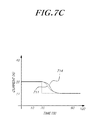
- FIGS. 7A to 7C are views for describing roles of the filter.
- the converter system 400 may change the number of converter modules to be operated according to processing power. For example, in a state where the processing power is 200 W (current of 20 A), the converter system 400 may operate one converter module (for example, the first converter module 231 ). Then, when the processing power increases to be 220 W (current of 22 A), the converter system 400 may operate two converter modules (for example, the first converter module 231 and the fourth converter module 234 ).
- FIG. 7A shows a current reference value transmitted to each of the converter modules 231 and 234 in the moment (20 second position) when the processing is changed from 200 W to 220 W.
- a line 710 shown on the left indicates a current reference value transmitted to the first converter module 231 and a line 720 shown on the bottom indicates a current reference value transmitted to the fourth converter module 234 .
- the converter system 400 transmits a current reference value of 20 A to the first converter module 231 and a current reference value of 0 A to the fourth converter module 234 by the second position. However, after the 20 second position, the converter system 400 transmits a current reference value of 11 A to the first converter module 231 and also a current reference value of 11 A to the fourth converter module 234 according to a change in the processing power. Since the converter system 400 operates converter modules in parallel in an interleaving type, the converter system 400 transmits the same current reference vale to the converter modules operating in parallel.
- FIG. 7B illustrates an output current of the first converter module 231 .
- a solid line 712 indicates an output current of the first converter module 231 and a dotted line 710 indicates a current reference value transmitted to the first converter module 231 .
- oscillation occurs in a 20 second position of the output current curved line 712 .
- the oscillation occurs due to a rapid change in the current reference value.
- the converter module has a predetermined control bandwidth. When a signal beyond the control bandwidth is input, the oscillation may occur in the output current as illustrated in FIG. 7B .
- the converter system 400 includes the filter 420 that filters a current reference value signal.
- the filter 420 may be a lowpass filter.
- a filter band corresponds to a frequency range lower than a current control cutoff frequency of the converter module.
- FIG. 7C illustrates an output current of the first converter module 231 when the filter is used. Specifically, in FIG. 7C , a solid line 714 indicates an output current of the first converter module 231 and a dotted line 711 indicates a current reference value transmitted to the first converter module 231 .
- a current reference value signal is filtered by the filter 420 and expressed by a soft curved line.
- the filter band may correspond to a frequency range lower than the control band. Accordingly, the filtered current reference value signal has a frequency characteristic lower than the control band of the converter module. When the frequency characteristic of the current reference value signal is within the control band, oscillation does not occur in the output current curved line 714 as illustrated in FIG. 7C .
- the reference value generator 416 may generate a current reference value for each of the converter modules 230 according to equation (1).
- n denotes time
- i denotes a converter module number
- a denotes the number of converter modules to be operated
- ⁇ i r denotes a difference between an input current (iin) and an output current (io)
- r denotes the total number of converter modules.
- e i (n) has a value of 1 with respect to the converter module to be operated with an ON/OFF value of an i th converter module in time of n and has a value of 0 with respect to the remaining converter modules.
- Equation (1) is applied when the input power becomes the same as the load power.
- an initial current reference value in the change time is determined by comparing the number of current operating modules and the number of previous operating modules in order to restrain a rapid change in the input current.
- FIG. 8 is a flowchart illustrating a process of a control of the converter system according to another embodiment of the present invention.
- the converter system 400 loads, to a memory, an efficiency map in which first parameters corresponding to processing power and second parameters corresponding to the number of converter modules which can process the processing power with the optimum efficiency are mapped in step S 800 .
- the converter system 400 configures a first parameter value according to a sensing value for input power or output power in step S 802 .
- the converter system 400 calculates a second parameter value by substituting the first parameter value into the efficiency map, selects the number of converter modules corresponding to the second parameter value as active converter modules from the converter modules, and transmits enable signals in step S 804 .
- the converter system 400 generates current reference value signals for some or all of the converter modules in step S 806 , and filters the current reference value signals and transmits the filtered current reference value signals to the converter modules in step S 808 .
- the converter system 400 controls currents of the converter modules according to the current reference value signals in step S 810 .
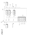
- FIG. 9 illustrates a converter system according to another embodiment of the present invention.
- a converter system 900 includes a plurality of current control type converter modules 230 connected in parallel to an output terminal of a fuel cell 440 .
- the converter system 900 may include a digital controller 910 .
- the digital controller 910 may include a memory 912 , a module selector 914 , a reference value generator 916 , and a total reference value generator 918 .
- the memory 912 may store the efficiency map in which first parameters corresponding to processing power of the converter system and second parameters corresponding to the number of converter modules which can process the processing power with the optimum efficiency are mapped.
- the total reference value generator 918 generates a command-value-for-total-current-reference-value and the reference value generator 916 generates current reference value signals (Iref_ 1 , Iref_ 2 , . . . Iref_n) for the respective converter modules 230 .
- the sum total of current reference values of the converter modules 230 is the same as the command-value-for-total-current-reference-value generated by the total reference value generator 918 .
- the module selector 914 configures a first parameter value according to the command-value-for-total-current-reference-value. Further, the module selector 914 calculates a second parameter value by substituting the first parameter value into the efficiency map. The module selector 914 may select the number of converter modules corresponding to the second parameter value as active converter modules from the converter modules and transmit enable signals Ena_ 1 , Ena_ 2 , . . . Ena_n).
- the total reference value generator 918 may control a change rate of the command-value-for-total-current-reference-value within a preset total command value change rate range.
- the stack may be damaged due to a rapid change in the output of the fuel cell 440 .
- the total reference value generator 918 may control the change rate of the command-value-for-total-current-reference-value within a preset range in order to prevent the rapid output change.
- the range may vary depending on characteristics of the fuel cell 440 . Further, a value of the range may be transmitted to the total reference value generator 918 according to a user's control.
- FIGS. 10A and 10B illustrate outputs of the fuel cell and converter modules.
- FIG. 10A shows a curved line 1010 of the output of the fuel cell 440 from the beginning to the entry into a normal state.
- FIG. 10 illustrates an expansion of part A of FIG. 10A and further shows an output curved line 1012 of the first converter module 231 and an output curved line 1014 of the second converter module 232 as well as the output curved line of the fuel cell 440 .
- the output of the fuel cell 440 gradually increases at an incline of b (2 W/s).
- the incline b is determined according to a change rate of the command-value-for-total-current-reference-value generated by the total reference value generator 918 .
- the total reference value generator may increase the command-value-for-total-current-reference-value until the output of the fuel cell 440 becomes a normal state.
- the module selector 914 may configure a first parameter value according to the command-value-for-total-current-reference-value and selects the predetermined number of active converter modules by substituting the first parameter value into the efficiency map, if the command-value-for-total-current-reference-value increases, the number of active converter modules may change at one time point.
- the number of active converter modules changes in a 20 second time position.
- Processing power of the converter system 900 is 20 W before the 20 second time position, but processing power of the converter system 900 is 22 W in a 21 second time position. Accordingly, the module selector 914 processes power by using the first converter module 231 before 20 seconds and processes power by using both the first converter module 231 and the second converter module 232 after 20 seconds.
- the converter system 900 may control the processing power of the converter modules to be uniformly distributed.
- the processing power of the converter system 900 at a 21 second time position is 22 W in FIG. 10B .
- the converter system 900 may uniformly distribute the processing power and control each of the first converter module 231 and the second converter module 232 to process power of 11 W.
- the output of the first converter module 231 rapidly decreases from 20 W to 10 W and the output of the second converter module 232 rapidly increases from 0 W to 10 W, so that the oscillation may occur in each of the converter modules.
- the oscillation may influence the output of the fuel cell 440 .
- the reference value generator 916 may control a change rate of the current reference value within a preset current reference value change rate range. Accordingly, the reference value generator 916 may prevent the output of each converter module from rapidly changing.
- the module selector 914 increases the number of active converter modules from one to two according to the increase in the processing power.
- the reference value generator 916 controls a change rate of the current reference value (see reference numerals c and d in FIG. 10B ) within a preset range such that the output of each converter module can gradually change.
- the preset current reference value change rate range may be a range determined by a current control cutoff frequency of the converter modules.
- the frequency of the current reference value change rate may be lower than the current control cutoff frequency of the converter modules 230 .
- the converter modules 230 may emit the stable output regardless of the change in the current reference value.
- the sum total of current reference value change rates of the converter modules may be the same as the change rate of the command-value-for-total-current-reference-value.
- the converter system 900 may maintain the change rate of the output of the fuel cell 440 in a predetermined value.
- the converter system 900 may have a problem in that all the load currents are not supplied.
- the converter system 900 may further include batteries connected to the output terminals of the converter modules 230 . The battery may perform a function of supplying the current while the converter system 900 cannot temporarily supply the current.
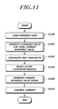
- FIG. 11 is a flowchart illustrating a process of a control of the converter system according to another embodiment of the present invention.
- the converter system 900 loads, to a memory, an efficiency map in which first parameters corresponding to processing power and second parameters corresponding to the number of converter modules which can process the processing power with the optimum efficiency are mapped in step S 1100 .
- the converter system 900 generates a command-value-for-total-current-reference-value in step S 1102 and configures a first parameter value according to the command-value-for-total-current-reference-value in step S 1104 .
- the converter system 900 calculates a second parameter value by substituting the first parameter value into the efficiency map, selects the number of converter modules corresponding to the second parameter value from the converter modules as active converter modules, and transmits an enable signal in step S 1106 .
- the converter system 900 generates current reference value signals for some or all of the converter modules. At this time, the converter system 900 controls a change rate of the current reference value within a preset current reference value change rate range and controls the sum total of the current reference values to be the same as the command-value-for-total-current-reference-value in step S 1108 .
- the converter system 900 controls currents of the converter modules by using the generated current reference value signals in step S 1110 .
- FIG. 12 illustrates an efficiency curved line of the converter system according to some of the embodiments of the present invention.
- a first efficiency curved line (curved line expressed by ⁇ ) indicates the efficiency of the converter system when the number of operating converter modules is different according to processing power (first control) and a second efficiency curved line (curved line expressed by *) indicates the efficiency of the converter system when four converter modules are controlled in parallel regardless of processing power (second control).
- values of the first efficiency curved line are larger than values of the second efficiency curved line (curved line expressed by *) until processing power becomes 400 W.
- the efficiency is the same since the four converter modules are controlled in parallel in the first control and the second control.
- the first control below 400 W has higher efficiency in comparison with the second control since the number of converter modules is controlled to have the optimum efficiency.
- the converter system controls the number of converter modules to create the optimum efficiency, thereby generating an effect in which a plurality of converter modules operating in parallel operate with high efficiency during entire load operation intervals.
Landscapes
- Engineering & Computer Science (AREA)
- Power Engineering (AREA)
- Dc-Dc Converters (AREA)
- Fuel Cell (AREA)
Abstract
Description
- This application claims priority from and the benefit under 35 U.S.C. §119(a) of Korean Patent Application No. 10-2014-0070659, filed on Jun. 11, 2014, which is hereby incorporated by reference for all purposes as if fully set forth herein.
- 1. Field of the Invention
- The present invention relates to a converter system converting power. More particularly, the present invention relates to a converter system technology for operating a plurality of converter modules in parallel with optimum efficiency.
- 2. Description of the Prior Art
- Unlike solar or wind power, fuel cells are representative renewable distributed energy sources of which an output can be controlled according to a user demand characteristic and are widely used as power supply sources of a mobile system such as an unmanned aerial vehicle, an automobile, a submarine and the like at present. Miniaturization and high power of fuel cell stacks applied to the mobile system are very important factors to reduce the weight of the system and improve the efficiency of the system.
- Meanwhile, a DC-DC converter is used for efficient power conversion of the high power fuel cell stack. When modules having the same capacity are arranged in parallel in an interleaving type, the DC-DC converter may relatively easily increase processing power and reduce current ripple.
- However, such a parallel arrangement type corresponds to a very advantageous structure to the reliability improvement and the increase in processing power, but has disadvantages in that power is easily non-uniformly processed between parallel modules and a high efficiency operation is difficult during entire load operation intervals. Particularly, the mobile system requires as long an operation as possible with limited fuel, and accordingly, loss reduction through the high efficiency of the DC-DC converter is a very important factor.
- Accordingly, an aspect of the present invention is to provide technologies related to a converter system and a method of controlling the same in which a plurality of converter modules operating in parallel operate with the high efficiency during entire load operation intervals.
- In accordance with an aspect of the present invention, a converter system is provided. The converter system includes: a plurality of converter modules connected to one power source in parallel; and a controller for storing mapping information of first parameters corresponding to processing power of the converter modules and second parameters corresponding to the number of converter modules that optimally process the processing power among the converter modules, configuring a value of the first parameter according to a measurement value of power input into the converter modules or power output from the converter modules, calculating a value of the second parameter by substituting the value of the first parameter into the mapping information, selecting the number of converter modules corresponding to the value of the second parameters as active converter modules from the converter modules and processing the processing power by using the active converter modules, and controlling output power of the active converter module to gradually increase or decrease in a transient state where the value of the second parameter is changed.
- In accordance with another aspect of the present invention, a converter system is provided. The converter system includes: a plurality of converter modules connected to one power source in parallel; and a controller for storing mapping information of first parameters corresponding to processing power of the converter modules and second parameters corresponding to the number of converter modules that optimally process the processing power among the converter modules, configuring a value of the first parameter according to a measurement value of power input into the converter modules or power output from the converter modules, calculating a value of the second parameter by substituting the value of the first parameter into the mapping information, and transmitting a current reference value to the converter modules based on an equation of
-
- (n denotes time, i denotes a number of a converter module, Iref_i(n) denotes a current reference value of an ith converter module in time of n, α denotes the number of converter modules to be operated and is determined according to the second parameter, Δir denotes a difference between an input current and an output current, r denotes the number of total converter modules, and ei(n) has a value of 1 for a converter module to be operated with an ON value of the ith converter module in time of n).
- In accordance with another aspect of the present invention, a converter system connected with a fuel cell is provided. The converter system includes: a plurality of current control type converter modules connected to an output terminal of the fuel cell in parallel; a memory for storing an efficiency map in which first parameters corresponding to processing power of the converter system and second parameters corresponding to the number of converter modules capable of processing the processing power with an optimum efficiency are mapped; a total reference value generator for generating a command-value-for-total-current-reference-value; a module selector for configuring a value of the first parameter according to the command-value-for-total-current-reference-value, calculating a value of the second parameter by substituting the value of the first parameter into the efficiency map, and selecting the number of converter modules corresponding to the value of the second parameter as active converter modules from the converter modules; and a reference value generator for generating a current reference value signal for each of the converter modules, wherein a sum total of current reference values of the converter modules is equal to the command-value-for-total-current-reference-value.
- In accordance with another aspect of the present invention, a converter system connected with a fuel cell is provided. The converter system includes: a plurality of current control type converter modules connected to an output terminal of the fuel cell in parallel; a memory for storing an efficiency map in which first parameters corresponding to processing power of the converter system and second parameters corresponding to the number of converter modules capable of processing the processing power with an optimum efficiency are mapped; a module selector for configuring a value of the first parameter according to a sensing value for input power or output power, calculating a value of the second parameter by substituting the value of the first parameter into the efficiency map, selecting the number of converter modules corresponding to the value of the second parameter as active converter modules from the converter modules, and transmitting enable signals; and a reference value generator for generating current reference value signals for some or all of the converter modules; and a filter for filtering the current reference value signals and transmitting the filtered current reference value signals to the converter modules.
- In accordance with another aspect of the present invention, a method of controlling a converter system including a plurality of converter modules connected to an output terminal of a fuel cell in parallel is provided. The method includes: loading, to a memory, an efficiency map in which first parameters corresponding to processing power of the converter system and second parameters corresponding to the number of converter modules which can process the processing power with an optimum efficiency are mapped; configuring a value of the first parameter according to a sensing value for input power or output power; calculating a value of the second parameter by substituting the value of the first parameter into the efficiency map, selecting the number of converter modules corresponding to the value of the second parameter as active converter modules from the converter modules, and transmitting enable signals; generating current reference value signals for some or all of the converter modules; filtering the current reference value signals and transmitting the filtered current reference value signals to the converter modules; and controlling currents of the converter modules.
- In accordance with another aspect of the present invention, a converter system connected with a fuel cell is provided. The converter system includes: a plurality of current control type converter modules connected to an output terminal of the fuel cell in parallel; a memory for storing an efficiency map in which first parameters corresponding to processing power of the converter system and second parameters corresponding to the number of converter modules capable of processing the processing power with an optimum efficiency; a total reference value generator for generating a command-value-for-total-current-reference-value; a module selector for configuring a value of the first parameter according to the command-value-for-total-current-reference-value, calculating a value of the second parameter by substituting the value of the first parameter into the efficiency map, selecting the number of converter modules corresponding to the value of the second parameter as active converter modules from the converter modules, and transmitting enable signals; and a reference value generator for generating a current reference value signal for each of the converter modules, wherein a sum total of current reference values of the converter modules is equal to the command-value-for-total-current-reference-value.
- In accordance with another aspect of the present invention, a method of controlling a converter system including a plurality of converter modules connected to an output terminal of a fuel cell in parallel is provided. The method includes: loading, to a memory, an efficiency map in which first parameters corresponding to processing power of the converter system and second parameters corresponding to the number of converter modules which can process the processing power with an optimum efficiency are mapped; generating a command-value-for-total-current-reference-value; configuring a value of the first parameter according to the command-value-for-total-current-reference-value; calculating a value of the second parameter by substituting the value of the first parameter into the efficiency map, selecting the number of converter modules corresponding to the value of the second parameter as active converter modules from the converter modules, and transmitting enable signals; generating current reference value signals for some or all of the converter modules, limiting a change rate of the current reference value within a preset current reference value change rate range, and controlling a sum total of the current reference values to be equal to the command-value-for-total-current-reference-value.
- As described above, according to the present invention, there is an effect in that a plurality of converter modules operating in parallel operate with the high efficiency during entire load operation intervals.
- The above and other objects, features and advantages of the present invention will be more apparent from the following detailed description taken in conjunction with the accompanying drawings, in which:
-
FIG. 1 is an efficiency curved line graph of an example of a converter module; -
FIG. 2 illustrates a converter system according to an embodiment of the present invention; -
FIG. 3 is a graph showing an example of an efficiency map stored in a memory ofFIG. 2 ; -
FIG. 4 illustrates a converter system according to another embodiment of the present invention; -
FIG. 5 illustrates a circuit model of the embodiment ofFIG. 4 ; -
FIGS. 6A and 6B illustrate an embodiment of the location of a filter; -
FIGS. 7A to 7C are views for describing roles of a filter; -
FIG. 8 is a flowchart illustrating a process of a control of a converter system according to another embodiment of the present invention; -
FIG. 9 illustrates a converter system according to another embodiment of the present invention; -
FIGS. 10A and 10B illustrate outputs of a fuel cell and converter modules; -
FIG. 11 is a flowchart illustrating a process of a control of a converter system according to another embodiment of the present invention; and -
FIG. 12 illustrates an efficiency curved line of a converter system according to some of embodiments of the present invention. -
FIG. 1 is an example of an efficiency curved line graph of a converter module. - Referring to
FIG. 1 , when a converter module processes power of 90 W, efficiency of the converter module becomes 97%. When the converter module processes power of 45 W, efficiency of the converter module becomes 94%. - It is assumed that a converter system operates, in parallel, two converter modules having such efficiency characteristics.
- When the converter system processes power of 90 W through two converter modules in parallel, each of the converter modules process power of 45 W and thus efficiency of the converter system becomes 94%.
- In contrast, when the converter system processes power of 90 W through one converter module, the corresponding converter module processes power of 90 W and thus efficiency of the converter system becomes 97%.
- Accordingly, processing power of 90 W through one converter module is advantageous to the converter system from an efficiency point of view.
- The converter system according to the present invention operates the number of converter modules which creates optimum efficiency according to power throughput to operate with high efficiency during entire load operation intervals.
- For example, in the above description, the converter system operates only one converter module without operating both the converter modules to process power of 90 W.
- Hereinafter, exemplary embodiments of the present invention will be described with reference to the accompanying drawings. In the following description, the same elements will be designated by the same reference numerals although they are shown in different drawings. Further, in the following description of the present invention, a detailed description of known functions and configurations incorporated herein will be omitted when it may make the subject matter of the present invention rather unclear.
- In addition, terms, such as first, second, A, B, (a), (b) or the like may be used herein when describing components of the present invention. These terms are merely used to distinguish one structural element from other structural elements, and a property, an order, a sequence and the like of a corresponding structural element are not limited by the term. It should be noted that if it is described in the specification that one component is “connected,” “coupled” or “joined” to another component, a third component may be “connected,” “coupled,” and “joined” between the first and second components, although the first component may be directly connected, coupled or joined to the second component.
-
FIG. 2 illustrates a converter system according to an embodiment of the present invention. - Referring to
FIG. 2 , aconverter system 200 includes a plurality ofconverter modules 230. - The plurality of
converter modules 230 are connected to each other in parallel. An input terminal of each of theconverter modules 230 is connected to apower source 240 and an output terminal of each of theconverter modules 230 is connected to aload 250. Theconverter module 230 converts power supplied from thepower source 240 and transmits the converted power to theload 250. - The
converter module 230 may have a different form according to the type of power supplied from thepower source 240 and the type of power consumed by theload 250. For example, when thepower source 240 supplies Alternating Current (AC) power and theload 250 consumes Direct Current (DC) power, theconverter module 230 may be a form of an AC-DC converter. Further, when thepower source 240 supplies DC power and theload 250 consumes AC power, theconverter module 230 may be a form of a DC-AC converter. Hereinafter, although an embodiment in which theconverter module 230 has a form of a DC-DC converter will be described for the convenience of the description, the present invention is not limited thereto. - The
converter module 230 may be a voltage control type converter or a current control type converter based on a control scheme. The voltage control type converter is a converter which controls an output voltage and an adapter is a representative example of the voltage control type converter. The current control type converter is a converter which controls an output current and a battery charger is a representative example of the current control type converter. Hereinafter, although an embodiment in which theconverter module 230 is the current control type converter will be described, the present invention is not limited thereto. Further, since the current control type converter generally includes a function of controlling an output voltage through a voltage feedback loop, the current control type converter should be understood as including a function of the voltage control type converter. - Meanwhile, the
converter system 200 may further include amemory 210 and acontroller 220. - The
memory 210 may store mapping information of first parameters corresponding to processing power of the converter modules or processing power of theconverter system 200 and second parameters corresponding to the number of converter modules which optimally process the processing power. - The mapping information may be stored in a form of an efficiency map, and the
memory 210 may store an efficiency map indicating the number of converter modules which can process processing power with optimum efficiency. -
FIG. 3 is a graph showing an example of an efficiency map stored in the memory ofFIG. 2 . - In
FIG. 3 , a horizontal axis represents power processed by theconverter system 200. Further, a vertical axis represents the number of converter modules which creates optimum efficiency for each of the processing power. - Referring to
FIG. 3 , when theconverter system 200 processes power of 100 W, the number of converter modules which create optimum efficiency is 1. When theconverter system 200 processes power of 200 W, the number of converter modules which creates optimum efficiency is 2. In the graph ofFIG. 3 , a boundary part may be understood as having a value of a previous state. For example, when processing power is 300 W in the graph, the number of converter modules may be 2 or 3. In this case, if the number of converter modules was 2 in a previous state, theconverter system 200 continuously maintains the number of converter modules as 2. In contrast, if the number of converter modules was 3 in a previous state, theconverter system 200 continuously maintains the number of converter modules as 3. - Such an efficiency map can be acquired through an experiment. For example, an engineer first configures processing power as 100 W, 200 W, . . . , 800 W and the like and may find the number of converter modules which creates maximum efficiency while changing the number of converter modules. The efficiency map may be determined according to values acquired through the experiment.
- The efficiency map may be acquired through calculation or modeling. For example, when there is a loss model of the converter module, the number of converter modules which generates a minimum loss in each of the processing power may be found using the loss model. The efficiency map may be determined according to a value acquired through the calculation.
- Meanwhile, in
FIG. 3 , one axis of the efficiency map is represented by processing power and the other axis is represented by the number of converter modules, but they are represented by other values in the efficiency map. - For example, one axis of the efficiency map may be represented by input power. Since the processing power of the
converter system 200 is proportional to the input power, the input power may be used as an index which replaces the processing power. - As a result, the efficiency map may be understood as mapping of first parameters corresponding to the processing power and second parameters corresponding to the number of converter modules which can process the processing power with the optimum efficiency. Here, the first parameter may be the processing power or the input power. Alternatively, the first parameter may be input current amounts. When a voltage is constant, since the input power is determined according to the input current amounts, the input current amounts may be used as an index corresponding to the processing power.
- The
controller 220 may control theconverter modules 230 by using the efficiency map. - Referring back to
FIG. 2 , thecontroller 220 may acquire a sensing value of input power or output power to configure a first parameter value corresponding to the processing power. - A
power sensor 261 may be located at the input terminal of theconverter system 200. Theconverter system 200 may acquire input power (Pin), input current (Iin), input voltage (Vin) or the like by using thepower sensor 261 of the input terminal. - Further, a
power sensor 262 may also be located at the output terminal of theconverter system 200. Theconverter system 200 may acquire output power (Po), output current (Io), output voltage (Vo) or the like by using thepower sensor 262 of the output terminal. - When the first parameter value is the input current, the
converter system 200 may configure the input current (Iin) acquired from thepower sensor 261 as the first parameter value. - When the first parameter value is the output power, the
converter system 262 may calculate an output power value by multiplying the output current (Io) and the output voltage (Vo) acquired from thepower sensor 262 and configure the output power value as the first parameter value. - When the first parameter value is configured, the
controller 220 may calculate a second parameter value (for example, a value corresponding to the number of converter modules) by substituting the first parameter value into the efficiency map. - The
controller 220 may select the number of converter modules corresponding to the calculated second parameter value as active converter modules and process processing power of theconverter system 200 by using the active converter modules. - Meanwhile, a state in which the second parameter value is changed may be defined as a transient state. At this time, the
controller 220 may control the output power of the active control module to gradually increase or decrease. - The
controller 220 may transmit a reference signal to theconverter module 230 and theconverter module 230 may control output power according to the reference signal. At this time, thecontroller 220 may control the output power of the active converter module to gradually increase or decrease by increasing or decreasing the reference signal in the transient state. - Further, the
controller 220 includes a digital filter or an analog filter and may transmit the reference signal to the converter modules via the digital filter or the analog filter. At this time, the digital filter or the analog filter may be a lowpass filter and a filter band may correspond to a frequency range lower than a current control cutoff frequency of the converter modules. - In addition, the
controller 220 may further include a Digital to Analog Converter (DAC) which converts a digital signal for the reference signal to an analog signal and transmit the reference signal via a digital filter located at a DAC front end or an analog filter located at a DAC rear end. - Meanwhile, the efficiency map may be stored in the form of a function having the first parameter as an input and the second parameter as an output. At this time, the
controller 220 may calculate a second parameter value by substituting a first parameter value into the function. - The efficiency map may be stored in the form of a table having the first parameter as a first group and the second parameter as a second group. At this time, the
controller 220 may calculate the second parameter value by using interpolation with respect to a value which is not listed in the first group. - When the second parameter value is calculated, the
controller 220 may operate the number of converter modules corresponding to the second parameter value among the converter modules. - The
controller 220 may select the number of converter modules corresponding to the second parameter value from the converter modules and transmit enable signals Ena_1, Ena_2, . . . Ena_n) to the selected converter modules. Further, thecontroller 220 may transmit disable signals (not shown) to converter modules which are not selected. - Each of the
converter modules 230 may or may not perform power conversion by using the enable signals (Ena_1, Ena_2, . . . Ena_n) or the disable signals (not shown). - Meanwhile, the
converter modules 230 may be current control type converters. Thecontroller 220 may transmit current reference values (Iref_1, Iref_2, . . . Iref_n) to the current controltype converter modules 230. At this time, each of theconverter modules 230 controls currents according to the received current reference values (Iref_1, Iref_2, . . . Iref_n). - The
controller 220 may selectively operate theconverter modules 230 by using the current reference values. For example, thecontroller 220 may select the number of converter modules corresponding to the second parameter value from the converter modules and transmit a current reference value corresponding to 0 Ampere (A) to converter modules which are not selected, so as not to operate the corresponding converter modules. -
FIG. 4 illustrates a converter system according to another embodiment of the present invention. - Referring to
FIG. 4 , aconverter system 400 includes a plurality of current controltype converter modules 230 connected in parallel to an output terminal of afuel cell 440. - Further, the
converter system 400 may include adigital controller 410 and afilter 420. - The
digital controller 410 may include amemory 412, amodule selector 414, and areference value generator 416. - The
memory 412 may store the efficiency map in which first parameters corresponding to processing power of the converter system and second parameters corresponding to the number of converter modules which can process the processing power with the optimum efficiency are mapped. - The
module selector 414 may configure a first parameter value according to a sensing value of input power or output power and calculate a second parameter value by substituting the first parameter value into the efficiency map. Themodule selector 414 may select the number of converter modules corresponding to the second parameter value as active converter modules from the converter modules and transmit enable signals Ena_1, Ena_2, . . . Ena_n) to the selected active converter modules. - The
reference value generator 416 may generate current reference value signals for some or all of the converter modules. For example, thereference value generator 416 may generate current reference value signals only for the active converter modules. -
FIG. 5 illustrates a circuit model according to the embodiment ofFIG. 4 . - Referring to
FIG. 5 , theconverter system 400 includes four converter modules. Here, afirst converter module 231 and afourth converter module 234 may be understood as examples of theconverter modules 230 illustrated inFIG. 4 . - In the embodiment of
FIG. 5 , theconverter system 400 has a DC/DC boost converter as a converter module for a non-isolated power conversion in a condition where an input voltage is lower than an output voltage. - More specifically, referring to
FIG. 5 , thefirst converter module 231 corresponds to a DC/DC boost converter including an inductor (L1) located at an input terminal line, a first switch (SW1) located at a ground terminal line, and a diode (D1) located at an output terminal line. Although not illustrated inFIG. 5 in detail, the remaining three converter modules may be all DC/DC boost converters. - The DC/DC boost converter has the same input current as a current (iL1) of the inductor (L1) and has an advantage in that an accurate control of an input current is possible when the current is controlled by a Pulse Width Modulation (PWM) method like the
first converter module 231. Thefuel cell 440 is required to perform accurate current control to prevent damage of the stack, so that theconverter system 400 uses the DC/DC boost converter as the converter module. - Further, the DC/DC boost converter has a feature of relatively easily increasing processing power and decreasing current ripple when modules having the same capacity are arranged in parallel in an interleaving type. In this respect, the
converter system 400 operates a plurality of converter modules in parallel. - Meanwhile, referring to
FIG. 5 , abattery 570 may be connected to the output terminal of theconverter system 400. The stack may be damaged due to a rapid change in the output of thefuel cell 440. As illustrated inFIG. 5 , when thebattery 570 is connected between the output terminal of theconverter system 400 and theload 250, thebattery 570 may cover the rapid change in a load current (io) and thus totally stabilize the system. - Referring to
FIG. 5 , thedigital controller 410 receives an input current (iin), an input voltage (vin), an output current (io), and a battery voltage (vb) as sensing values. Here, since the output voltage of theconverter system 400 is fixed to the battery voltage (vb), the battery voltage (vb) may be actually understood as the output voltage of theconverter system 400. - In the efficiency map, the first parameter may be an input current or input power. When the first parameter is the input power, the
digital controller 410 may configure the first parameter value according to the product of a current value (iin) and a voltage value (vin) of the input power. - Referring to
FIG. 5 , thedigital controller 410 transmits enable signals (Ena_1, . . . Ena_4) and current reference value signals (Iref_1, . . . Iref_4) as output signals. At this time, a Digital to Analog Converter (DAC) 522 that converts a digital output signal of areference value generator 416 to an analog signal and afilter 420 are located at a current reference value signal output terminal. - The
filter 420 may be an analog filter or a digital filter. When thefilter 420 is an analog filter, thefilter 420 is located at a rear end of theDAC 522 as illustrated inFIG. 5 . When thefilter 420 is a digital filter, thefilter 420 may be located at a front end of theDAC 522. -
FIGS. 6A and 6B illustrate an embodiment of the location of the filter. - Referring to
FIG. 6A , when the filter is ananalog filter 420 a, the filter is located between theDAC 522 and theconverter module 230. At this time, a current reference value signal (digital signal) output from thedigital controller 410 is converted into an analog signal by theDAC 522 and then output. Further, the analog signal is filtered through theanalog filter 420 a and then finally transmitted to theconverter module 230. - Referring to
FIG. 6B , when the filter is adigital filter 420 b, the filter is located between thedigital controller 410 and theDAC 522. At this time, a current reference value signal (digital signal) output from thedigital controller 410 is filtered through thedigital filter 420 b and then transmitted to theDAC 522. TheDAC 522 converts the filtered digital signal to an analog signal and finally transmits the analog signal to theconverter module 230. Meanwhile, thedigital filter 420 b may be implemented in a digital processor which is the same as thereference value generator 416. -
FIGS. 7A to 7C are views for describing roles of the filter. - The
converter system 400 may change the number of converter modules to be operated according to processing power. For example, in a state where the processing power is 200 W (current of 20 A), theconverter system 400 may operate one converter module (for example, the first converter module 231). Then, when the processing power increases to be 220 W (current of 22 A), theconverter system 400 may operate two converter modules (for example, thefirst converter module 231 and the fourth converter module 234). -
FIG. 7A shows a current reference value transmitted to each of theconverter modules FIG. 7A , aline 710 shown on the left indicates a current reference value transmitted to thefirst converter module 231 and aline 720 shown on the bottom indicates a current reference value transmitted to thefourth converter module 234. - Referring to
FIG. 7A , theconverter system 400 transmits a current reference value of 20 A to thefirst converter module 231 and a current reference value of 0 A to thefourth converter module 234 by the second position. However, after the 20 second position, theconverter system 400 transmits a current reference value of 11 A to thefirst converter module 231 and also a current reference value of 11 A to thefourth converter module 234 according to a change in the processing power. Since theconverter system 400 operates converter modules in parallel in an interleaving type, theconverter system 400 transmits the same current reference vale to the converter modules operating in parallel. -
FIG. 7B illustrates an output current of thefirst converter module 231. Specifically, inFIG. 7B , asolid line 712 indicates an output current of thefirst converter module 231 and adotted line 710 indicates a current reference value transmitted to thefirst converter module 231. - Referring to
FIG. 7B , oscillation occurs in a 20 second position of the output currentcurved line 712. The oscillation occurs due to a rapid change in the current reference value. - The converter module has a predetermined control bandwidth. When a signal beyond the control bandwidth is input, the oscillation may occur in the output current as illustrated in
FIG. 7B . - In order not to generate the oscillation, the
converter system 400 includes thefilter 420 that filters a current reference value signal. Thefilter 420 may be a lowpass filter. A filter band corresponds to a frequency range lower than a current control cutoff frequency of the converter module. -
FIG. 7C illustrates an output current of thefirst converter module 231 when the filter is used. Specifically, inFIG. 7C , asolid line 714 indicates an output current of thefirst converter module 231 and adotted line 711 indicates a current reference value transmitted to thefirst converter module 231. - Referring to
FIG. 7C , a current reference value signal is filtered by thefilter 420 and expressed by a soft curved line. As described above, the filter band may correspond to a frequency range lower than the control band. Accordingly, the filtered current reference value signal has a frequency characteristic lower than the control band of the converter module. When the frequency characteristic of the current reference value signal is within the control band, oscillation does not occur in the output currentcurved line 714 as illustrated inFIG. 7C . - Meanwhile, the
reference value generator 416 may generate a current reference value for each of theconverter modules 230 according to equation (1). -
- In equation (1), n denotes time, i denotes a converter module number, a denotes the number of converter modules to be operated, Δir denotes a difference between an input current (iin) and an output current (io), and r denotes the total number of converter modules. Further, ei(n) has a value of 1 with respect to the converter module to be operated with an ON/OFF value of an ith converter module in time of n and has a value of 0 with respect to the remaining converter modules.
- Equation (1) is applied when the input power becomes the same as the load power. When the number of modules is changed according to the efficiency map, an initial current reference value in the change time is determined by comparing the number of current operating modules and the number of previous operating modules in order to restrain a rapid change in the input current.
-
FIG. 8 is a flowchart illustrating a process of a control of the converter system according to another embodiment of the present invention. - Referring to
FIG. 8 , theconverter system 400 loads, to a memory, an efficiency map in which first parameters corresponding to processing power and second parameters corresponding to the number of converter modules which can process the processing power with the optimum efficiency are mapped in step S800. - Further, the
converter system 400 configures a first parameter value according to a sensing value for input power or output power in step S802. - When the first parameter value is configured, the
converter system 400 calculates a second parameter value by substituting the first parameter value into the efficiency map, selects the number of converter modules corresponding to the second parameter value as active converter modules from the converter modules, and transmits enable signals in step S804. - The
converter system 400 generates current reference value signals for some or all of the converter modules in step S806, and filters the current reference value signals and transmits the filtered current reference value signals to the converter modules in step S808. - Further, the
converter system 400 controls currents of the converter modules according to the current reference value signals in step S810. -
FIG. 9 illustrates a converter system according to another embodiment of the present invention. - Referring to
FIG. 9 , aconverter system 900 includes a plurality of current controltype converter modules 230 connected in parallel to an output terminal of afuel cell 440. - Further, the
converter system 900 may include adigital controller 910. - The
digital controller 910 may include amemory 912, amodule selector 914, areference value generator 916, and a totalreference value generator 918. - The
memory 912 may store the efficiency map in which first parameters corresponding to processing power of the converter system and second parameters corresponding to the number of converter modules which can process the processing power with the optimum efficiency are mapped. - The total
reference value generator 918 generates a command-value-for-total-current-reference-value and thereference value generator 916 generates current reference value signals (Iref_1, Iref_2, . . . Iref_n) for therespective converter modules 230. However, the sum total of current reference values of theconverter modules 230 is the same as the command-value-for-total-current-reference-value generated by the totalreference value generator 918. - The
module selector 914 configures a first parameter value according to the command-value-for-total-current-reference-value. Further, themodule selector 914 calculates a second parameter value by substituting the first parameter value into the efficiency map. Themodule selector 914 may select the number of converter modules corresponding to the second parameter value as active converter modules from the converter modules and transmit enable signals Ena_1, Ena_2, . . . Ena_n). - Meanwhile, the total
reference value generator 918 may control a change rate of the command-value-for-total-current-reference-value within a preset total command value change rate range. - The stack may be damaged due to a rapid change in the output of the
fuel cell 440. The totalreference value generator 918 may control the change rate of the command-value-for-total-current-reference-value within a preset range in order to prevent the rapid output change. The range may vary depending on characteristics of thefuel cell 440. Further, a value of the range may be transmitted to the totalreference value generator 918 according to a user's control. -
FIGS. 10A and 10B illustrate outputs of the fuel cell and converter modules. Specifically,FIG. 10A shows acurved line 1010 of the output of thefuel cell 440 from the beginning to the entry into a normal state. Further,FIG. 10 illustrates an expansion of part A ofFIG. 10A and further shows an outputcurved line 1012 of thefirst converter module 231 and an outputcurved line 1014 of the second converter module 232 as well as the output curved line of thefuel cell 440. - Referring to
FIG. 10A , the output of thefuel cell 440 gradually increases at an incline of b (2 W/s). The incline b is determined according to a change rate of the command-value-for-total-current-reference-value generated by the totalreference value generator 918. - Meanwhile, as illustrated in
FIG. 10A , the total reference value generator may increase the command-value-for-total-current-reference-value until the output of thefuel cell 440 becomes a normal state. However, since themodule selector 914 may configure a first parameter value according to the command-value-for-total-current-reference-value and selects the predetermined number of active converter modules by substituting the first parameter value into the efficiency map, if the command-value-for-total-current-reference-value increases, the number of active converter modules may change at one time point. - Referring to
FIG. 10B , the number of active converter modules changes in a 20 second time position. - Processing power of the
converter system 900 is 20 W before the 20 second time position, but processing power of theconverter system 900 is 22 W in a 21 second time position. Accordingly, themodule selector 914 processes power by using thefirst converter module 231 before 20 seconds and processes power by using both thefirst converter module 231 and the second converter module 232 after 20 seconds. - When the number of active converter modules changes, the
converter system 900 may control the processing power of the converter modules to be uniformly distributed. For example, the processing power of theconverter system 900 at a 21 second time position is 22 W inFIG. 10B . At this time, theconverter system 900 may uniformly distribute the processing power and control each of thefirst converter module 231 and the second converter module 232 to process power of 11 W. - However, when the number of active converter modules changes, if such a control (uniformly distributing processing power to converter modules) is made, the output of each converter module rapidly changes and the oscillation described with reference to
FIG. 7 may occur in each converter module. - For example, when such a control (uniformly distributing processing power to converter modules) is made at the 20 second time position in
FIG. 10B , the output of thefirst converter module 231 rapidly decreases from 20 W to 10 W and the output of the second converter module 232 rapidly increases from 0 W to 10 W, so that the oscillation may occur in each of the converter modules. The oscillation may influence the output of thefuel cell 440. - The
reference value generator 916 may control a change rate of the current reference value within a preset current reference value change rate range. Accordingly, thereference value generator 916 may prevent the output of each converter module from rapidly changing. - Referring to
FIG. 10B , themodule selector 914 increases the number of active converter modules from one to two according to the increase in the processing power. At this time, thereference value generator 916 controls a change rate of the current reference value (see reference numerals c and d inFIG. 10B ) within a preset range such that the output of each converter module can gradually change. - The preset current reference value change rate range may be a range determined by a current control cutoff frequency of the converter modules. For example, the frequency of the current reference value change rate may be lower than the current control cutoff frequency of the
converter modules 230. When the frequency of the current reference value change rate is controlled to be lower than the current control cutoff frequency, theconverter modules 230 may emit the stable output regardless of the change in the current reference value. - Meanwhile, the sum total of current reference value change rates of the converter modules may be the same as the change rate of the command-value-for-total-current-reference-value. For example, in
FIG. 10B , an equation of b=c+d may be established. When the sum total of the current reference value change rates of the converter modules is the same as the change rate of the command-value-for-total-current-reference-value, theconverter system 900 may maintain the change rate of the output of thefuel cell 440 in a predetermined value. - Meanwhile, when the total
reference value generator 918 limits the change rate of the command-value-for-total-current-reference-value within a predetermined range, theconverter system 900 may have a problem in that all the load currents are not supplied. In order to solve the above problem, theconverter system 900 may further include batteries connected to the output terminals of theconverter modules 230. The battery may perform a function of supplying the current while theconverter system 900 cannot temporarily supply the current. -
FIG. 11 is a flowchart illustrating a process of a control of the converter system according to another embodiment of the present invention. - Referring to
FIG. 11 , theconverter system 900 loads, to a memory, an efficiency map in which first parameters corresponding to processing power and second parameters corresponding to the number of converter modules which can process the processing power with the optimum efficiency are mapped in step S1100. - Further, the
converter system 900 generates a command-value-for-total-current-reference-value in step S1102 and configures a first parameter value according to the command-value-for-total-current-reference-value in step S1104. - In addition, the
converter system 900 calculates a second parameter value by substituting the first parameter value into the efficiency map, selects the number of converter modules corresponding to the second parameter value from the converter modules as active converter modules, and transmits an enable signal in step S1106. - The
converter system 900 generates current reference value signals for some or all of the converter modules. At this time, theconverter system 900 controls a change rate of the current reference value within a preset current reference value change rate range and controls the sum total of the current reference values to be the same as the command-value-for-total-current-reference-value in step S1108. - The
converter system 900 controls currents of the converter modules by using the generated current reference value signals in step S1110. - The converter system and a method of controlling the same according to some of the embodiments of the present invention have been described.
-
FIG. 12 illustrates an efficiency curved line of the converter system according to some of the embodiments of the present invention. - In
FIG. 12 , a first efficiency curved line (curved line expressed by Δ) indicates the efficiency of the converter system when the number of operating converter modules is different according to processing power (first control) and a second efficiency curved line (curved line expressed by *) indicates the efficiency of the converter system when four converter modules are controlled in parallel regardless of processing power (second control). - Referring to
FIG. 12 , values of the first efficiency curved line (curved line expressed by A) are larger than values of the second efficiency curved line (curved line expressed by *) until processing power becomes 400 W. Above 400 W, the efficiency is the same since the four converter modules are controlled in parallel in the first control and the second control. However, the first control below 400 W has higher efficiency in comparison with the second control since the number of converter modules is controlled to have the optimum efficiency. - As described above, the converter system according to embodiments of the present invention controls the number of converter modules to create the optimum efficiency, thereby generating an effect in which a plurality of converter modules operating in parallel operate with high efficiency during entire load operation intervals.
- Further, the terms “includes”, “constitutes”, or “has” mentioned above mean that a corresponding structural element is included unless they have no reverse meaning. Accordingly, it should be interpreted that the terms may not exclude but further include other structural elements. All the terms that are technical, scientific or otherwise agree with the meanings as understood by a person skilled in the art unless defined to the contrary. Common terms as found in dictionaries should be interpreted in the context of the related technical writings not too ideally or impractically unless the present disclosure expressly defines them so.
- Although the embodiments of the present invention have been described for illustrative purposes, those skilled in the art will appreciate that various modifications, additions and substitutions are possible, without departing from the scope and spirit of the invention. Accordingly, the embodiments disclosed in the present invention are merely to not limit but describe the technical spirit of the present invention. Further, the scope of the technical spirit of the present invention is not limited by the embodiments. The scope of the present invention shall be construed on the basis of the accompanying claims in such a manner that all of the technical ideas included within the scope equivalent to the claims belong to the present invention.
Claims (18)
Applications Claiming Priority (2)
| Application Number | Priority Date | Filing Date | Title |
|---|---|---|---|
| KR10-2014-0070659 | 2014-06-11 | ||
| KR1020140070659A KR101582471B1 (en) | 2014-06-11 | 2014-06-11 | A converter system using efficient map and control method thereof |
Publications (2)
| Publication Number | Publication Date |
|---|---|
| US20150364982A1 true US20150364982A1 (en) | 2015-12-17 |
| US9774254B2 US9774254B2 (en) | 2017-09-26 |
Family
ID=54836996
Family Applications (1)
| Application Number | Title | Priority Date | Filing Date |
|---|---|---|---|
| US14/525,846 Active 2036-03-25 US9774254B2 (en) | 2014-06-11 | 2014-10-28 | Converter system using efficient map and method of controlling same |
Country Status (2)
| Country | Link |
|---|---|
| US (1) | US9774254B2 (en) |
| KR (1) | KR101582471B1 (en) |
Cited By (18)
| Publication number | Priority date | Publication date | Assignee | Title |
|---|---|---|---|---|
| US20150367735A1 (en) * | 2014-06-20 | 2015-12-24 | Cooper Technologies Company | Multi-phase bidirectional dc to dc power converter circuits, systems and methods with transient stress control |
| US20160181797A1 (en) * | 2014-12-17 | 2016-06-23 | The Boeing Company | Solar array simulation using common power supplies |
| US20160311328A1 (en) * | 2015-04-21 | 2016-10-27 | Samsung Electronics Co., Ltd. | Battery control method and apparatus, battery module, and battery pack |
| DE102016203062A1 (en) * | 2016-02-26 | 2017-08-31 | Bayerische Motoren Werke Aktiengesellschaft | Converter device and method for operating a converter device |
| JP2019068526A (en) * | 2017-09-28 | 2019-04-25 | パナソニックIpマネジメント株式会社 | Converter system |
| US10361584B2 (en) | 2016-11-16 | 2019-07-23 | Korea Institute Of Energy Research | System for managing energy, method of managing energy, and method of predicting energy demand |
| EP3609064A4 (en) * | 2017-04-05 | 2020-04-01 | Panasonic Intellectual Property Management Co., Ltd. | LASER EXCITATION ENERGY SOURCE |
| US20210091599A1 (en) * | 2018-06-08 | 2021-03-25 | Huawei Technologies Co., Ltd. | Wireless Charging Apparatus and Terminal Using Same |
| US11257173B2 (en) | 2016-11-08 | 2022-02-22 | Korea Institute Of Energy Research | Complex energy system in bidirectional energy network and control method thereof |
| CN114374250A (en) * | 2022-02-08 | 2022-04-19 | 东莞市美一瓦科技有限公司 | Parallel high-power boost conversion processing system and fuel cell power supply system |
| US11379025B2 (en) | 2019-05-16 | 2022-07-05 | Samsung Electronics Co., Ltd. | Electronic device for performing power management and method for operating the same |
| US20220278621A1 (en) * | 2021-02-26 | 2022-09-01 | Denso Corporation | Power conversion apparatus |
| JP2022132052A (en) * | 2021-02-26 | 2022-09-07 | 株式会社デンソー | power converter |
| US20230127837A1 (en) * | 2021-10-26 | 2023-04-27 | Infineon Technologies Austria Ag | Method and apparatus for period detection-based control of regulation control parameter |
| EP4181377A1 (en) * | 2021-11-12 | 2023-05-17 | Soltec Innovations, S.L. | Power supply and battery charging arrangement for feeding a solar tracker and method thereof |
| US12002396B2 (en) | 2020-12-18 | 2024-06-04 | Lx Semicon Co., Ltd. | Power management circuit and timing controller for display device |
| US12204390B2 (en) | 2019-05-16 | 2025-01-21 | Samsung Electronics Co., Ltd. | Electronic device for performing power management and method for operating the same |
| WO2025244835A1 (en) * | 2024-05-22 | 2025-11-27 | Caterpillar Inc. | Optimisation of the efficiency of parallel dc-dc converters in a battery-powered machine |
Families Citing this family (10)
| Publication number | Priority date | Publication date | Assignee | Title |
|---|---|---|---|---|
| KR101859007B1 (en) * | 2016-01-25 | 2018-06-27 | 계명대학교 산학협력단 | control method for improving efficiency of LDC through parallel architecture and apparatus thereof |
| KR102085240B1 (en) * | 2018-07-06 | 2020-03-05 | 한국에너지기술연구원 | Parallel Power Converting System And ControlL Method Thereof |
| CN114499182A (en) * | 2020-10-23 | 2022-05-13 | 华为数字能源技术有限公司 | Power supply and current sampling method |
| KR102435947B1 (en) * | 2020-11-25 | 2022-08-24 | 주식회사 브이씨텍 | Power allocation method and apparatus for increase efficiency of dc/dc converter |
| KR102630314B1 (en) * | 2021-09-07 | 2024-01-29 | (주)성호전자 | AC-DC converter employing high efficiency load sharing with parrallel structure |
| KR102603197B1 (en) * | 2021-11-12 | 2023-11-17 | 한국에너지기술연구원 | Efficiency optimized converter system |
| KR20240040231A (en) | 2022-09-21 | 2024-03-28 | 현대자동차주식회사 | Vehicle including dc-dc converter and method of contrlling for the same |
| KR102719129B1 (en) * | 2022-10-12 | 2024-10-17 | 신문수 | Parallel power conversion system with optimal efficiency and method for controlling thereof |
| KR102679487B1 (en) * | 2023-09-12 | 2024-07-01 | (주)성호전자 | AC-DC converter employing load sharing with parrallel structure |
| WO2026005268A1 (en) * | 2024-06-26 | 2026-01-02 | 삼성전자주식회사 | Electronic circuit for converter and electronic device including same |
Citations (1)
| Publication number | Priority date | Publication date | Assignee | Title |
|---|---|---|---|---|
| US6246222B1 (en) * | 2000-08-30 | 2001-06-12 | National Semiconductor Corporation | Switching DC-to-DC converter and conversion method with rotation of control signal channels relative to paralleled power channels |
Family Cites Families (6)
| Publication number | Priority date | Publication date | Assignee | Title |
|---|---|---|---|---|
| US7157890B1 (en) * | 2005-10-25 | 2007-01-02 | Microchip Technology Inc. | Using pulse width modulation in the control of load sharing between paralleled power supplies |
| JP4967588B2 (en) * | 2006-10-17 | 2012-07-04 | トヨタ自動車株式会社 | Converter control device |
| JP5275688B2 (en) * | 2008-06-04 | 2013-08-28 | 住友重機械工業株式会社 | Converter device |
| JP5464323B2 (en) * | 2009-05-27 | 2014-04-09 | トヨタ自動車株式会社 | Converter control device |
| KR101319989B1 (en) | 2012-04-25 | 2013-10-18 | 한국에너지기술연구원 | Apparatus and method for controlling plural power converting modules, and apparatus and method for analizing electric energy imbalance |
| KR101390641B1 (en) | 2012-05-07 | 2014-04-30 | 한국에너지기술연구원 | System and method for converting electric power, and apparatus and method for controlling the system |
-
2014
- 2014-06-11 KR KR1020140070659A patent/KR101582471B1/en active Active
- 2014-10-28 US US14/525,846 patent/US9774254B2/en active Active
Patent Citations (1)
| Publication number | Priority date | Publication date | Assignee | Title |
|---|---|---|---|---|
| US6246222B1 (en) * | 2000-08-30 | 2001-06-12 | National Semiconductor Corporation | Switching DC-to-DC converter and conversion method with rotation of control signal channels relative to paralleled power channels |
Cited By (27)
| Publication number | Priority date | Publication date | Assignee | Title |
|---|---|---|---|---|
| US9802493B2 (en) * | 2014-06-20 | 2017-10-31 | Cooper Technologies Company | Multi-phase bidirectional DC to DC power converter circuits, systems and methods with transient stress control |
| US20150367735A1 (en) * | 2014-06-20 | 2015-12-24 | Cooper Technologies Company | Multi-phase bidirectional dc to dc power converter circuits, systems and methods with transient stress control |
| US20160181797A1 (en) * | 2014-12-17 | 2016-06-23 | The Boeing Company | Solar array simulation using common power supplies |
| US20190232801A1 (en) * | 2015-04-21 | 2019-08-01 | Samsung Electronics Co., Ltd. | Battery control method and apparatus, battery module, and battery pack |
| US20160311328A1 (en) * | 2015-04-21 | 2016-10-27 | Samsung Electronics Co., Ltd. | Battery control method and apparatus, battery module, and battery pack |
| US10293693B2 (en) * | 2015-04-21 | 2019-05-21 | Samsung Electronics Co., Ltd. | Battery control method and apparatus, battery module, and battery pack |
| US10730398B2 (en) * | 2015-04-21 | 2020-08-04 | Samsung Electronics Co., Ltd. | Battery control method and apparatus, battery module, and battery pack |
| DE102016203062A1 (en) * | 2016-02-26 | 2017-08-31 | Bayerische Motoren Werke Aktiengesellschaft | Converter device and method for operating a converter device |
| US11257173B2 (en) | 2016-11-08 | 2022-02-22 | Korea Institute Of Energy Research | Complex energy system in bidirectional energy network and control method thereof |
| US10361584B2 (en) | 2016-11-16 | 2019-07-23 | Korea Institute Of Energy Research | System for managing energy, method of managing energy, and method of predicting energy demand |
| EP3609064A4 (en) * | 2017-04-05 | 2020-04-01 | Panasonic Intellectual Property Management Co., Ltd. | LASER EXCITATION ENERGY SOURCE |
| JP2019068526A (en) * | 2017-09-28 | 2019-04-25 | パナソニックIpマネジメント株式会社 | Converter system |
| US12500449B2 (en) * | 2018-06-08 | 2025-12-16 | Huawei Technologies Co., Ltd. | Wireless charging apparatus and terminal using same |
| US20210091599A1 (en) * | 2018-06-08 | 2021-03-25 | Huawei Technologies Co., Ltd. | Wireless Charging Apparatus and Terminal Using Same |
| US11379025B2 (en) | 2019-05-16 | 2022-07-05 | Samsung Electronics Co., Ltd. | Electronic device for performing power management and method for operating the same |
| US12204390B2 (en) | 2019-05-16 | 2025-01-21 | Samsung Electronics Co., Ltd. | Electronic device for performing power management and method for operating the same |
| US12603029B2 (en) | 2020-12-18 | 2026-04-14 | Lx Semicon Co., Ltd. | Power management circuit and timing controller for display device |
| US12002396B2 (en) | 2020-12-18 | 2024-06-04 | Lx Semicon Co., Ltd. | Power management circuit and timing controller for display device |
| US20220278621A1 (en) * | 2021-02-26 | 2022-09-01 | Denso Corporation | Power conversion apparatus |
| JP2022132052A (en) * | 2021-02-26 | 2022-09-07 | 株式会社デンソー | power converter |
| JP7691907B2 (en) | 2021-02-26 | 2025-06-12 | 株式会社デンソー | Power Converter |
| US12095373B2 (en) * | 2021-02-26 | 2024-09-17 | Denso Corporation | Power conversion apparatus |
| US20230127837A1 (en) * | 2021-10-26 | 2023-04-27 | Infineon Technologies Austria Ag | Method and apparatus for period detection-based control of regulation control parameter |
| US12081144B2 (en) * | 2021-10-26 | 2024-09-03 | Infineon Technologies Austria Ag | Method and apparatus for period detection-based control of regulation control parameter |
| EP4181377A1 (en) * | 2021-11-12 | 2023-05-17 | Soltec Innovations, S.L. | Power supply and battery charging arrangement for feeding a solar tracker and method thereof |
| CN114374250A (en) * | 2022-02-08 | 2022-04-19 | 东莞市美一瓦科技有限公司 | Parallel high-power boost conversion processing system and fuel cell power supply system |
| WO2025244835A1 (en) * | 2024-05-22 | 2025-11-27 | Caterpillar Inc. | Optimisation of the efficiency of parallel dc-dc converters in a battery-powered machine |
Also Published As
| Publication number | Publication date |
|---|---|
| US9774254B2 (en) | 2017-09-26 |
| KR101582471B1 (en) | 2016-01-07 |
| KR20150142743A (en) | 2015-12-23 |
Similar Documents
| Publication | Publication Date | Title |
|---|---|---|
| US9774254B2 (en) | Converter system using efficient map and method of controlling same | |
| US10464441B2 (en) | Charging facility and energy management method for charging facility | |
| US6590370B1 (en) | Switching DC-DC power converter and battery charger for use with direct oxidation fuel cell power source | |
| US7663342B2 (en) | Apparatus, system, and method for controlling multiple power supplies | |
| US20150214754A1 (en) | Method of controlling charging and discharging of battery energy storage device and the battery energy storage device for the same | |
| CN111106601B (en) | Control of DC voltage distribution system | |
| CN107612333B (en) | A control circuit and method based on a double-tube buck-boost converter | |
| CN102170150A (en) | Power storage system | |
| US10122180B2 (en) | Bus conditioner for an aircraft power system | |
| US20230223761A1 (en) | Regulating Power Between Power Sources in a Photovoltaic Power System | |
| US8427097B2 (en) | Hybrid electrical power source | |
| KR20190052353A (en) | Converter system and method for controlling modules by group | |
| KR20160041062A (en) | Power control method for ship | |
| JP2017153284A (en) | SOLAR POWER GENERATION SYSTEM, ITS CONTROL METHOD, AND MOBILE BODY HAVING SOLAR POWER GENERATION SYSTEM | |
| CN103094954A (en) | Control device and control method | |
| JP2015192549A (en) | Power conversion device and power conversion method | |
| JP2013099207A (en) | Control apparatus and control method | |
| EP4597778A2 (en) | Energy storage system and operating method thereof | |
| EP4597779A2 (en) | Energy storage system and operating method thereof | |
| EP4597777A2 (en) | Energy storage system and operating method thereof | |
| KR102603197B1 (en) | Efficiency optimized converter system | |
| US20250253696A1 (en) | Energy storage system and operating method thereof | |
| JP2025537563A (en) | Power conversion equipment | |
| CN120414634A (en) | Energy storage system and operation method thereof | |
| Kumar et al. | Performance-Optimized EV Fast Charger using Bridgeless Switched-Inductor Cuk Converter and STSMC |
Legal Events
| Date | Code | Title | Description |
|---|---|---|---|
| AS | Assignment |
Owner name: KOREA INSTITUTE OF ENERGY RESEARCH, KOREA, REPUBLI Free format text: ASSIGNMENT OF ASSIGNORS INTEREST;ASSIGNORS:CHAE, SU YONG;SONG, YUJIN;OH, SEA SEUNG;AND OTHERS;REEL/FRAME:034052/0456 Effective date: 20141021 |
|
| STCF | Information on status: patent grant |
Free format text: PATENTED CASE |
|
| MAFP | Maintenance fee payment |
Free format text: PAYMENT OF MAINTENANCE FEE, 4TH YR, SMALL ENTITY (ORIGINAL EVENT CODE: M2551); ENTITY STATUS OF PATENT OWNER: SMALL ENTITY Year of fee payment: 4 |
|
| MAFP | Maintenance fee payment |
Free format text: PAYMENT OF MAINTENANCE FEE, 8TH YR, SMALL ENTITY (ORIGINAL EVENT CODE: M2552); ENTITY STATUS OF PATENT OWNER: SMALL ENTITY Year of fee payment: 8 |