US20150253876A1 - Method for operating an operating device for a motor vehicle - Google Patents
Method for operating an operating device for a motor vehicle Download PDFInfo
- Publication number
- US20150253876A1 US20150253876A1 US14/435,277 US201314435277A US2015253876A1 US 20150253876 A1 US20150253876 A1 US 20150253876A1 US 201314435277 A US201314435277 A US 201314435277A US 2015253876 A1 US2015253876 A1 US 2015253876A1
- Authority
- US
- United States
- Prior art keywords
- sensor value
- actual sensor
- actual
- rotary actuator
- setpoint
- Prior art date
- Legal status (The legal status is an assumption and is not a legal conclusion. Google has not performed a legal analysis and makes no representation as to the accuracy of the status listed.)
- Granted
Links
Images


Classifications
-
- G—PHYSICS
- G06—COMPUTING OR CALCULATING; COUNTING
- G06F—ELECTRIC DIGITAL DATA PROCESSING
- G06F3/00—Input arrangements for transferring data to be processed into a form capable of being handled by the computer; Output arrangements for transferring data from processing unit to output unit, e.g. interface arrangements
- G06F3/01—Input arrangements or combined input and output arrangements for interaction between user and computer
- G06F3/03—Arrangements for converting the position or the displacement of a member into a coded form
- G06F3/033—Pointing devices displaced or positioned by the user, e.g. mice, trackballs, pens or joysticks; Accessories therefor
- G06F3/0362—Pointing devices displaced or positioned by the user, e.g. mice, trackballs, pens or joysticks; Accessories therefor with detection of one-dimensional [1D] translations or rotations of an operating part of the device, e.g. scroll wheels, sliders, knobs, rollers or belts
-
- G—PHYSICS
- G01—MEASURING; TESTING
- G01D—MEASURING NOT SPECIALLY ADAPTED FOR A SPECIFIC VARIABLE; ARRANGEMENTS FOR MEASURING TWO OR MORE VARIABLES NOT COVERED IN A SINGLE OTHER SUBCLASS; TARIFF METERING APPARATUS; MEASURING OR TESTING NOT OTHERWISE PROVIDED FOR
- G01D5/00—Mechanical means for transferring the output of a sensing member; Means for converting the output of a sensing member to another variable where the form or nature of the sensing member does not constrain the means for converting; Transducers not specially adapted for a specific variable
- G01D5/12—Mechanical means for transferring the output of a sensing member; Means for converting the output of a sensing member to another variable where the form or nature of the sensing member does not constrain the means for converting; Transducers not specially adapted for a specific variable using electric or magnetic means
- G01D5/244—Mechanical means for transferring the output of a sensing member; Means for converting the output of a sensing member to another variable where the form or nature of the sensing member does not constrain the means for converting; Transducers not specially adapted for a specific variable using electric or magnetic means influencing characteristics of pulses or pulse trains; generating pulses or pulse trains
- G01D5/245—Mechanical means for transferring the output of a sensing member; Means for converting the output of a sensing member to another variable where the form or nature of the sensing member does not constrain the means for converting; Transducers not specially adapted for a specific variable using electric or magnetic means influencing characteristics of pulses or pulse trains; generating pulses or pulse trains using a variable number of pulses in a train
-
- G—PHYSICS
- G01—MEASURING; TESTING
- G01D—MEASURING NOT SPECIALLY ADAPTED FOR A SPECIFIC VARIABLE; ARRANGEMENTS FOR MEASURING TWO OR MORE VARIABLES NOT COVERED IN A SINGLE OTHER SUBCLASS; TARIFF METERING APPARATUS; MEASURING OR TESTING NOT OTHERWISE PROVIDED FOR
- G01D5/00—Mechanical means for transferring the output of a sensing member; Means for converting the output of a sensing member to another variable where the form or nature of the sensing member does not constrain the means for converting; Transducers not specially adapted for a specific variable
- G01D5/26—Mechanical means for transferring the output of a sensing member; Means for converting the output of a sensing member to another variable where the form or nature of the sensing member does not constrain the means for converting; Transducers not specially adapted for a specific variable characterised by optical transfer means, i.e. using infrared, visible, or ultraviolet light
- G01D5/32—Mechanical means for transferring the output of a sensing member; Means for converting the output of a sensing member to another variable where the form or nature of the sensing member does not constrain the means for converting; Transducers not specially adapted for a specific variable characterised by optical transfer means, i.e. using infrared, visible, or ultraviolet light with attenuation or whole or partial obturation of beams of light
- G01D5/34—Mechanical means for transferring the output of a sensing member; Means for converting the output of a sensing member to another variable where the form or nature of the sensing member does not constrain the means for converting; Transducers not specially adapted for a specific variable characterised by optical transfer means, i.e. using infrared, visible, or ultraviolet light with attenuation or whole or partial obturation of beams of light the beams of light being detected by photocells
- G01D5/347—Mechanical means for transferring the output of a sensing member; Means for converting the output of a sensing member to another variable where the form or nature of the sensing member does not constrain the means for converting; Transducers not specially adapted for a specific variable characterised by optical transfer means, i.e. using infrared, visible, or ultraviolet light with attenuation or whole or partial obturation of beams of light the beams of light being detected by photocells using displacement encoding scales
- G01D5/3473—Circular or rotary encoders
Definitions
- the present invention relates to a method for operating an operator control device for a motor vehicle. Furthermore, the present invention relates to an operator control device for a motor vehicle.
- Appropriate operator control devices are provided for operating functional devices of a motor vehicle.
- Said operator control devices can comprise a rotary actuator or rotary encoder.
- Contemporary rotary actuators have mechanical latching positions in which they latch along their rotational direction. These latching positions are perceived haptically by the user or by the operator.
- Such rotary manual actuators have been in use millions of times for years and are employed, for example, as volume adjusters, in air conditioning operator control components or in a central input unit in a motor vehicle.
- the rotary actuators usually have appropriate coding elements which can be detected with a sensor.
- the coding elements can comprise one or more magnets which are detected with a Hall sensor.
- the coding elements can be formed by electrical contacts which are contacted by slip contacts.
- the coding elements can also be formed by corresponding recesses which can be detected with an optical sensor.
- DE 10 2005 055 307 A1 describes a rotary actuator with an incremental rotational angle encoder for use in a motor vehicle.
- a coding element with periodic cutouts is attached to the shaft of the rotary actuator. Rotating the rotary actuator and the associated rotation of the coding element causes the cutouts to rotate through the detection range of the photoelectric barrier. This causes the analog output voltage of a photosensor to be modulated.
- An incremental rotational angle of the rotary actuator can be assigned to the profile of the analog output voltage by evaluation electronics.
- DE 10 2006 060 808 A1 discloses an angle sensor for detecting the rotational angle of a component with a ring- or circular disk-like magnet.
- a Hall element is arranged by which a digital signal which is dependent on the rotational position of the magnet can be generated.
- an analog signal of a magneto-resistive sensor element can be assigned, as a function of the digital signal, to a first 180° angular range or to a second 180° angular range, following the first angular range, of a 360° angular range.
- US 2012/0056761 A1 describes a rotatable input device for a motor vehicle.
- An optical or magnetic sensor can be used to detect the rotational angle of the input device.
- US 2010/0057273 A1 discloses a control system for a motor vehicle.
- the control system has an operator control element which can be embodied as a rotary actuator or pushbutton actuator.
- DE 10 2009 051730 A1 describes a multi-function operator control device of a motor vehicle with a rotary actuator.
- a rotary actuator Arranged on the rotary actuator is at least one magnet which interacts in a contactless fashion with a Hall sensor.
- a rotational haptic element is provided with which individual latching stages for the rotary actuator are predefined.
- One potential object is to make the operator control of an operator control device, in particular of a rotary actuator, easier and more intuitive.
- the inventors propose a method for operating an operator control device for a motor vehicle, wherein the operator control device has a rotary actuator which is rotatably mounted on a holding element, and a coding element, comprises detecting a first actual sensor value using coding of the coding element in the current rotational position of the rotary actuator, determining a current rotational angle between the rotary actuator and the holding element on the basis of the detected first actual sensor value, respectively providing at least one setpoint sensor value at predetermined rotational angles between the rotary actuator and the holding element, assigning the detected first actual sensor value to one of the at least one setpoint sensor values and adapting the first actual sensor value to the setpoint sensor value, assigned thereto, for the determination of the current rotational angle.
- the operator control device can be arranged in the dashboard or in the center console of the motor vehicle.
- the motor vehicle can also comprise a plurality of operator control devices with which functional devices such as, for example, an air conditioning system, a navigation system, an operator control device with an associated display, an entertainment system or the like can be actuated.
- the operator control device comprises a rotary actuator which can also be embodied as a rotary actuator/pushbutton actuator.
- the operator control device comprises a coding element which can be arranged, for example, on the rotary actuator.
- the coding element can be arranged, for example, along the circumferential direction of the rotary actuator or a shaft of the rotary actuator.
- the operator control device comprises a sensor device with which coding of the coding element can be detected.
- the sensor device can, for example, be arranged in a positionally fixed fashion on the holding element or a housing of the operator control device.
- the coding element can comprise, for example, one or more magnets and the sensor device can comprise a Hall sensor.
- the coding element can have breakthroughs or a predetermined geometry which can be sensed with an optical sensor of the sensor device. The use of sliding contacts is also conceivable.
- Four predefined rotational angles of the rotary actuator with respect to the holding element setpoint sensor values can be stored on a storage device of the operator control device. These setpoint sensor values may have been correspondingly detected in advance with a precision rotary encoder for predetermined angles.
- the setpoint sensor values can also be stored by the manufacturer in the storage device.
- an actual sensor value is then detected using the coding of the coding element. This actual sensor value is compared with the setpoint sensor values which are stored in the memory. The actual sensor value is then assigned to the closest setpoint sensor value. The actual sensor value is then adapted to the setpoint sensor value assigned thereto.
- a corresponding calibration of the actual sensor value can therefore be carried out continuously during operation of the operator control device.
- the adaptation of the actual sensor value to the setpoint sensor value the current rotational angle can be determined more precisely.
- a multiplicity of latching stages are preferably predefined to the rotary actuator in along its rotational direction and the first actual sensor value is assigned to the at least one setpoint sensor value between two of the latching stages.
- the operator control device can have a latching device with which a plurality of latching stages or latching positions along its rotational direction are predefined to the rotary actuator. These latching positions can be generated mechanically with a latching cam or by appropriate magnets. During the rotation of the rotary actuator, the latter latches in at the latching positions.
- the discrete latching positions which bring about a high-quality operator control sensation for the user as a result of the haptic feedback, are present in the operator control device. Furthermore, slight deflections of the rotary actuator before the latching in at the next latching position can be detected with the sensor device. As a result, in addition to the latching positions the intermediate positions between the latching stages can also be easily detected with high resolution and further processed correspondingly.
- the first actual sensor value is multiplied by a factor and/or an offset is added to the first actual sensor value for the purpose of adaptation.
- the respective actual sensor value can be multiplied by a factor.
- an offset for the actual sensor value can be determined. The actual sensor value can therefore be adapted particularly easily to the setpoint sensor value.
- the first and a second actual sensor value are determined for the predefined rotational position and a first and a second setpoint sensor value are respectively provided at predetermined rotational angles.
- the operator control device can have two sensor devices which are arranged offset with respect to one another along the rotational direction of the rotary actuator.
- a first actual sensor value is provided with the first sensor device and a second actual sensor value with the second sensor device using the coding of the coding element.
- a first and a second setpoint sensor value are predefined for each predetermined rotational angle of the rotary actuator with respect to the holding element.
- the first actual sensor value is assigned to the first setpoint sensor value and/or the second actual sensor value is assigned to the second setpoint sensor value.
- the associated value of the first setpoint sensor value can be plotted with respect to the associated second setpoint sensor value for each predefined rotational angle in a diagram. As a result the measured value pair of the first actual sensor value and the second actual sensor value can easily be assigned to the corresponding pair of the first setpoint sensor value and the second setpoint sensor value.
- the first actual sensor value and/or the second actual sensor value are preferably adapted using a difference between the first actual sensor value and the first setpoint sensor value and/or a difference between the second actual sensor value and the second setpoint sensor value.
- the pair of actual sensor values is compared the corresponding pairs of setpoint sensor values. For this purpose, the distance between the pair of actual sensor values and the respective pairs of setpoint sensor values is determined. The distance is calculated from the sum of the absolute value of the first actual sensor value minus the first setpoint sensor value and the absolute value of the second actual sensor value minus the second setpoint sensor value. In order to determine the distance it is also possible to use other methods such as, for example, a binary search. The sum of the distances squared is also suitable, as are other customary methods for quantifying distance.
- the smallest distance between the pair of the actual sensor values and the associated pair of the setpoint sensor values is then obtained.
- the determination of the distance can always be carried out with the adapted actual sensor values.
- the current rotational angle of the rotary actuator can be determined particularly accurately.
- fabrication tolerances, temperature influences, the drift of the sensor device or the like can be compensated.
- the actual sensor values are always very close to the setpoint sensor values, and the faults due to the distance method are therefore minimized.
- the first actual sensor value and/or the second actual sensor value are adapted in a rotational position of the rotary actuator by virtue of the fact that the first actual sensor is in a predefined value range.
- rough calibration of the operator control device is carried out.
- the sensor can be arranged, in particular, in such a way that the first actual sensor value and the second actual sensor value have substantially the same value.
- Such rough calibration can be carried out, for example, at the start of the system in order to determine an overall amplification for adapting the actual sensor values to the setpoint sensor values.
- the rough calibration is particularly efficient if the first actual sensor value and the second actual sensor value have substantially equal values and a small offset for adapting the actual sensor values is present.
- the rough calibration takes place before the use of the rotary actuator. The distance iteration must be terminated before the calibration.
- the factor is determined during operation of the operator control device in a position of the rotary actuator in which the first actual sensor value or the second actual sensor value are at a maximum. Subsequent to the rough calibration, corresponding fine calibration can be carried out.
- the factor for adapting the first actual sensor values to the setpoint sensor values is firstly determined. The determination of the factor can be carried out during the activation of the operator control device by the user. In the vicinity of a maximum of the first actual sensor value, the rotational angle of the second actual sensor value is broadly determined. The factor for the first actual sensor value can be determined in this range. The factor for the second actual sensor value can be determined analogously.
- the offset is determined during operation of the operator control device in a position of the rotary actuator in which the first actual sensor value or the second actual sensor value are at a minimum.
- the determination or the calibration of the offset is carried out during the activation of the operator control device by the operator.
- the rotational angle of the second actual sensor value is broadly determined.
- the offset for the first actual sensor value can be determined in this range.
- the offset for the second actual sensor value can be determined analogously.
- the inventors also propose an operator control device for a motor vehicle, which comprises a rotary actuator which is rotatably mounted on a holding element, a coding element, at least one sensor device for detecting a first actual sensor value using coding of the coding element in the current rotational position of the rotary actuator and a computing device for determining a current rotational angle between the rotary actuator and the holding element on the basis of the detected first actual sensor value, wherein the operator control device has a storage device for respectively providing at least one setpoint sensor value at predetermined rotational angles between the rotary actuator and the holding element, and the computing device is designed to assign the detected first actual sensor value to one of the at least one setpoint sensor values and to adapt the first actual sensor value to the setpoint sensor value assigned thereto, for the determination of the current rotational angle.
- FIG. 1 shows an operator control device for a motor vehicle in a schematic illustration
- FIG. 2 shows an operator control device for a motor vehicle in a further embodiment
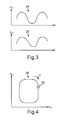
- FIG. 3 shows the signals of the first actual sensor values and second actual sensor values as a function of time
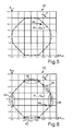
- FIG. 4 shows a diagram in which the first actual sensor values are plotted against the second actual sensor values
- FIG. 5 shows a diagram in which the first setpoint sensor values are plotted against the second setpoint sensor values
- FIG. 6 shows a diagram according to FIG. 5 in a further embodiment.
- FIG. 1 shows a schematic illustration of an operator control device 10 for a motor vehicle in a plan view.
- the operator control device 10 is used to perform operator control of a functional device of a motor vehicle.
- a functional device can be an air conditioning system, a navigation system, an operator control device with an associated display, an entertainment system or the like.
- the operator control device 10 comprises a rotary actuator which is rotatably mounted on a holding element (not illustrated here).
- the operator control device 10 has a latching device by which a plurality of latching stages are predefined to the rotary actuator along the rotational direction r.
- the operator control device 10 comprises a coding element 12 .
- the coding element 12 can be arranged on the rotary actuator.
- the coding element 12 is formed here by four permanent magnets 14 which are arranged along the circumferential direction of the operator control device 10 .
- the operator control device 10 comprises a first sensor device 16 and a second sensor device 18 which are embodied as Hall sensors in the present example. The distance between the two sensor devices 16 , 18 corresponds half the spatial extent of a permanent magnet 14 along the circumferential direction. If the rotary actuator is rotated by an operator, the coding element 12 is also rotated with the rotary actuator. In the two sensor devices 16 , 18 , a sensor signal is generated as a function of the rotational position of the rotary actuator.
- the sensor signals have a substantially analog profile since the transition between the magnetization of the North Poles N and of the South Poles S of the permanent magnets 14 is fluid.
- the sensor signals can be fed to an analog/digital converter, as a result of which a first actual sensor value x act is provided by the first sensor device 16 , and a second actual sensor value y act is provided by the second sensor device 18 .
- FIG. 2 shows an operator control device 10 in a further embodiment.
- the coding element 12 is formed by four segments 20 which are arranged along the circumferential direction of the operator device control 10 .
- a lighting element 22 is arranged in an interior space formed by the segments 20 .
- the lighting element 22 respectively forms, together with the two sensor devices 16 , 18 which are embodied as photosensors in the present example, a photoelectric barrier which is interrupted by the segments 20 when the coding element 12 rotates.
- a first actual sensor value x act is provided here too by the first sensor device 16
- a second actual sensor value y act is provided by the second sensor device 18 .
- FIG. 3 shows the time profile of the first actual sensor value x act in a first graph 24 .
- the second graph 26 shows the time profile of the second actual sensor value y act .
- the time profile of the first actual sensor values x act and the time profile of the second actual sensor values y act have a substantially sinusoidal profile. In this context, the time profile of the second actual sensor values y act is offset with respect to the profile of the first actual sensor values x act .
- FIG. 4 shows a graph 28 in which the second actual sensor values y act are plotted as a function of the first actual sensor values x act for predetermined rotational angles ⁇ of the rotary actuator with respect to the holding element.
- the actual sensor values x act and y act can be plotted for predefined rotational angles ⁇ between two latching stages of the rotary actuator. If the rotary actuator is moved into a specific rotational position, the first sensor device 16 provides a first actual sensor value x act , and the second sensor device 18 provides a second actual sensor value y act . This is characterized in FIG. 4 by the point 30 .
- FIG. 5 shows a graph 32 in which second setpoint sensor values y setp are plotted as a function of the first setpoint sensor values x setp for predetermined rotational angles ⁇ of the rotary actuator with respect to the holding element.
- the setpoint sensor values x setp and y setp are determined, for example, using measurements with a rotational angle encoder.
- the setpoint sensor values x setp and y setp may have been determined for predetermined rotational angles ⁇ between two latching stages of the rotary actuator.
- the point 30 which characterizes the current actual sensor values x act and y act in the current rotational position of the rotary actuator, is also illustrated in the graph 32 .
- the two actual sensor values x act and y act are then assigned to a pair of setpoint sensor values x setp and y setp .
- the distance between the pair of actual sensor values x act and y act and the instantaneously closest pair of setpoint sensor values x setp and y setp is determined.
- the distance can be calculated according to the following formula:
- the pair of actual sensor values x act and y act is then assigned to the pair of setpoint sensor values x setp and y setp which are at the smallest distance from the actual sensor values x act and y act .
- an offset can be added to the actual sensor values x act and y act .
- the adaptation of the actual sensor values x act and y act is illustrated in FIG. 6 .
- a rough calibration is performed.
- the value zero is predefined as a starting value for the offset and the value one is predefined for the factor.
- the rough calibration is carried out in a position of rest of the operator control element.
- the rough calibration is preferably carried out when the rotary actuator is in a rotational position in which the actual sensor values x act and y act are substantially the same. This is characterized by the region 34 .
- a factor for adapting the actual sensor values x act and y act can be calculated according to the following formula:
- factor calibration of the actual sensor values x act and y act takes place.
- the calibration of the factor takes place during operation of the operator control device 10 .
- the factor is calibrated for the first actual sensor value x act . This takes place in a rotational position of the rotary actuator in which the first actual sensor value x act is at a maximum. This is characterized in FIG. 6 by the region 36 . In this region, the rotational angle ⁇ is determined in particular by the second actual sensor value y act .
- the factor is calculated as follows:
- the factor is calibrated for the second actual sensor value y act .
- the rotational angle ⁇ is determined in particular by the first actual sensor value x act .
- the calibration takes place of the offset for the actual sensor values x act and y act which is also performed during operation of the operator control device 10 .
- the offset for the first actual sensor value x act is calibrated. This takes place in a rotational position of the rotary actuator in which the first actual sensor values x act is at a minimum. This is characterized by the region 40 . In this region, the rotational angle ⁇ is determined in particular by the second actual sensor value y act .
- the offset is calculated according to the following formula:
- Offset x setp ⁇ x act .
- the offset for the second actual sensor value y act is calibrated. This takes place in a rotational position of the rotary actuator in which the second actual sensor value y act is at a minimum. This is characterized by the region 42 . In this region, the rotational angle ⁇ is determined in particular by the first actual sensor value x act .
Landscapes
- Physics & Mathematics (AREA)
- General Physics & Mathematics (AREA)
- Engineering & Computer Science (AREA)
- General Engineering & Computer Science (AREA)
- Theoretical Computer Science (AREA)
- Human Computer Interaction (AREA)
- Measurement Of Length, Angles, Or The Like Using Electric Or Magnetic Means (AREA)
- Mechanical Control Devices (AREA)
- Length Measuring Devices With Unspecified Measuring Means (AREA)
Abstract
Description
- This application is based on and hereby claims priority to International Application No. PCT/EP2013/001732 filed on Jun. 12, 2013 and German Application No. 10 2012 019 995.3 filed on Oct. 12, 2012, the contents of which are hereby incorporated by reference.
- The present invention relates to a method for operating an operator control device for a motor vehicle. Furthermore, the present invention relates to an operator control device for a motor vehicle.
- Appropriate operator control devices are provided for operating functional devices of a motor vehicle. Said operator control devices can comprise a rotary actuator or rotary encoder. Contemporary rotary actuators have mechanical latching positions in which they latch along their rotational direction. These latching positions are perceived haptically by the user or by the operator. Such rotary manual actuators have been in use millions of times for years and are employed, for example, as volume adjusters, in air conditioning operator control components or in a central input unit in a motor vehicle. The rotary actuators usually have appropriate coding elements which can be detected with a sensor. The coding elements can comprise one or more magnets which are detected with a Hall sensor. Furthermore, the coding elements can be formed by electrical contacts which are contacted by slip contacts. The coding elements can also be formed by corresponding recesses which can be detected with an optical sensor.
- In this context,
DE 10 2005 055 307 A1 describes a rotary actuator with an incremental rotational angle encoder for use in a motor vehicle. A coding element with periodic cutouts is attached to the shaft of the rotary actuator. Rotating the rotary actuator and the associated rotation of the coding element causes the cutouts to rotate through the detection range of the photoelectric barrier. This causes the analog output voltage of a photosensor to be modulated. An incremental rotational angle of the rotary actuator can be assigned to the profile of the analog output voltage by evaluation electronics. - DE 10 2006 060 808 A1 discloses an angle sensor for detecting the rotational angle of a component with a ring- or circular disk-like magnet. In the region of the magnetic field of the magnet, a Hall element is arranged by which a digital signal which is dependent on the rotational position of the magnet can be generated. In addition, an analog signal of a magneto-resistive sensor element can be assigned, as a function of the digital signal, to a first 180° angular range or to a second 180° angular range, following the first angular range, of a 360° angular range.
- Furthermore, US 2012/0056761 A1 describes a rotatable input device for a motor vehicle. An optical or magnetic sensor can be used to detect the rotational angle of the input device.
- In addition, US 2010/0057273 A1 discloses a control system for a motor vehicle. The control system has an operator control element which can be embodied as a rotary actuator or pushbutton actuator.
- Finally, DE 10 2009 051730 A1 describes a multi-function operator control device of a motor vehicle with a rotary actuator. Arranged on the rotary actuator is at least one magnet which interacts in a contactless fashion with a Hall sensor. Furthermore, a rotational haptic element is provided with which individual latching stages for the rotary actuator are predefined.
- One potential object is to make the operator control of an operator control device, in particular of a rotary actuator, easier and more intuitive.
- The inventors propose a method for operating an operator control device for a motor vehicle, wherein the operator control device has a rotary actuator which is rotatably mounted on a holding element, and a coding element, comprises detecting a first actual sensor value using coding of the coding element in the current rotational position of the rotary actuator, determining a current rotational angle between the rotary actuator and the holding element on the basis of the detected first actual sensor value, respectively providing at least one setpoint sensor value at predetermined rotational angles between the rotary actuator and the holding element, assigning the detected first actual sensor value to one of the at least one setpoint sensor values and adapting the first actual sensor value to the setpoint sensor value, assigned thereto, for the determination of the current rotational angle.
- The operator control device can be arranged in the dashboard or in the center console of the motor vehicle. The motor vehicle can also comprise a plurality of operator control devices with which functional devices such as, for example, an air conditioning system, a navigation system, an operator control device with an associated display, an entertainment system or the like can be actuated. The operator control device comprises a rotary actuator which can also be embodied as a rotary actuator/pushbutton actuator. The operator control device comprises a coding element which can be arranged, for example, on the rotary actuator. The coding element can be arranged, for example, along the circumferential direction of the rotary actuator or a shaft of the rotary actuator. In addition, the operator control device comprises a sensor device with which coding of the coding element can be detected. The sensor device can, for example, be arranged in a positionally fixed fashion on the holding element or a housing of the operator control device. As a result of the coding of the coding element, at least one actual sensor value is generated in the sensor device. The coding element can comprise, for example, one or more magnets and the sensor device can comprise a Hall sensor. Alternatively, the coding element can have breakthroughs or a predetermined geometry which can be sensed with an optical sensor of the sensor device. The use of sliding contacts is also conceivable.
- Four predefined rotational angles of the rotary actuator with respect to the holding element setpoint sensor values can be stored on a storage device of the operator control device. These setpoint sensor values may have been correspondingly detected in advance with a precision rotary encoder for predetermined angles. The setpoint sensor values can also be stored by the manufacturer in the storage device. During operation of the operator control device, an actual sensor value is then detected using the coding of the coding element. This actual sensor value is compared with the setpoint sensor values which are stored in the memory. The actual sensor value is then assigned to the closest setpoint sensor value. The actual sensor value is then adapted to the setpoint sensor value assigned thereto. A corresponding calibration of the actual sensor value can therefore be carried out continuously during operation of the operator control device. By virtue of the adaptation of the actual sensor value to the setpoint sensor value, the current rotational angle can be determined more precisely.
- A multiplicity of latching stages are preferably predefined to the rotary actuator in along its rotational direction and the first actual sensor value is assigned to the at least one setpoint sensor value between two of the latching stages. The operator control device can have a latching device with which a plurality of latching stages or latching positions along its rotational direction are predefined to the rotary actuator. These latching positions can be generated mechanically with a latching cam or by appropriate magnets. During the rotation of the rotary actuator, the latter latches in at the latching positions. By virtue of the assignment of the actual sensor value, which is determined using the coding of the coding element, to the setpoint sensor value, the rotational angle between the individual latching stages can then also be detected particularly precisely. The discrete latching positions, which bring about a high-quality operator control sensation for the user as a result of the haptic feedback, are present in the operator control device. Furthermore, slight deflections of the rotary actuator before the latching in at the next latching position can be detected with the sensor device. As a result, in addition to the latching positions the intermediate positions between the latching stages can also be easily detected with high resolution and further processed correspondingly.
- In one embodiment, the first actual sensor value is multiplied by a factor and/or an offset is added to the first actual sensor value for the purpose of adaptation. In order to be able to adapt the actual sensor value incrementally to the respective setpoint sensor value during operation of the operator control device, the respective actual sensor value can be multiplied by a factor. Alternatively or additionally, an offset for the actual sensor value can be determined. The actual sensor value can therefore be adapted particularly easily to the setpoint sensor value.
- In one embodiment, using the coding of the coding element the first and a second actual sensor value are determined for the predefined rotational position and a first and a second setpoint sensor value are respectively provided at predetermined rotational angles. The operator control device can have two sensor devices which are arranged offset with respect to one another along the rotational direction of the rotary actuator. A first actual sensor value is provided with the first sensor device and a second actual sensor value with the second sensor device using the coding of the coding element. In the storage device of the operator control device, a first and a second setpoint sensor value are predefined for each predetermined rotational angle of the rotary actuator with respect to the holding element. By virtue of the detection of two actual sensor values, the rotational angle between the rotary actuator and the holding element can be detected more precisely.
- In one refinement, the first actual sensor value is assigned to the first setpoint sensor value and/or the second actual sensor value is assigned to the second setpoint sensor value. For this purpose, the associated value of the first setpoint sensor value can be plotted with respect to the associated second setpoint sensor value for each predefined rotational angle in a diagram. As a result the measured value pair of the first actual sensor value and the second actual sensor value can easily be assigned to the corresponding pair of the first setpoint sensor value and the second setpoint sensor value.
- The first actual sensor value and/or the second actual sensor value are preferably adapted using a difference between the first actual sensor value and the first setpoint sensor value and/or a difference between the second actual sensor value and the second setpoint sensor value. The pair of actual sensor values is compared the corresponding pairs of setpoint sensor values. For this purpose, the distance between the pair of actual sensor values and the respective pairs of setpoint sensor values is determined. The distance is calculated from the sum of the absolute value of the first actual sensor value minus the first setpoint sensor value and the absolute value of the second actual sensor value minus the second setpoint sensor value. In order to determine the distance it is also possible to use other methods such as, for example, a binary search. The sum of the distances squared is also suitable, as are other customary methods for quantifying distance. Given a sufficiently frequent signal evaluation, the smallest distance between the pair of the actual sensor values and the associated pair of the setpoint sensor values is then obtained. In this context, the determination of the distance can always be carried out with the adapted actual sensor values. As a result, the current rotational angle of the rotary actuator can be determined particularly accurately. In addition, fabrication tolerances, temperature influences, the drift of the sensor device or the like can be compensated. As a result of the calibration described here, the actual sensor values are always very close to the setpoint sensor values, and the faults due to the distance method are therefore minimized.
- In a further embodiment, the first actual sensor value and/or the second actual sensor value are adapted in a rotational position of the rotary actuator by virtue of the fact that the first actual sensor is in a predefined value range. Firstly, rough calibration of the operator control device is carried out. During the rough calibration the sensor can be arranged, in particular, in such a way that the first actual sensor value and the second actual sensor value have substantially the same value. Such rough calibration can be carried out, for example, at the start of the system in order to determine an overall amplification for adapting the actual sensor values to the setpoint sensor values. The rough calibration is particularly efficient if the first actual sensor value and the second actual sensor value have substantially equal values and a small offset for adapting the actual sensor values is present. In this context, the rough calibration takes place before the use of the rotary actuator. The distance iteration must be terminated before the calibration.
- In a further embodiment, the factor is determined during operation of the operator control device in a position of the rotary actuator in which the first actual sensor value or the second actual sensor value are at a maximum. Subsequent to the rough calibration, corresponding fine calibration can be carried out. In the latter, the factor for adapting the first actual sensor values to the setpoint sensor values is firstly determined. The determination of the factor can be carried out during the activation of the operator control device by the user. In the vicinity of a maximum of the first actual sensor value, the rotational angle of the second actual sensor value is broadly determined. The factor for the first actual sensor value can be determined in this range. The factor for the second actual sensor value can be determined analogously.
- In a further refinement, the offset is determined during operation of the operator control device in a position of the rotary actuator in which the first actual sensor value or the second actual sensor value are at a minimum. The determination or the calibration of the offset is carried out during the activation of the operator control device by the operator. In a range in which the first actual sensor value is at a minimum, the rotational angle of the second actual sensor value is broadly determined. The offset for the first actual sensor value can be determined in this range. The offset for the second actual sensor value can be determined analogously.
- The inventors also propose an operator control device for a motor vehicle, which comprises a rotary actuator which is rotatably mounted on a holding element, a coding element, at least one sensor device for detecting a first actual sensor value using coding of the coding element in the current rotational position of the rotary actuator and a computing device for determining a current rotational angle between the rotary actuator and the holding element on the basis of the detected first actual sensor value, wherein the operator control device has a storage device for respectively providing at least one setpoint sensor value at predetermined rotational angles between the rotary actuator and the holding element, and the computing device is designed to assign the detected first actual sensor value to one of the at least one setpoint sensor values and to adapt the first actual sensor value to the setpoint sensor value assigned thereto, for the determination of the current rotational angle.
- The advantages and developments described above in relation to the method can be transferred in a similar way to the operator control device.
- These and other objects and advantages of the present invention will become more apparent and more readily appreciated from the following description of the preferred embodiments, taken in conjunction with the accompanying drawings of which:
-
FIG. 1 shows an operator control device for a motor vehicle in a schematic illustration; -
FIG. 2 shows an operator control device for a motor vehicle in a further embodiment; -
FIG. 3 shows the signals of the first actual sensor values and second actual sensor values as a function of time; -
FIG. 4 shows a diagram in which the first actual sensor values are plotted against the second actual sensor values; -
FIG. 5 shows a diagram in which the first setpoint sensor values are plotted against the second setpoint sensor values; and -
FIG. 6 shows a diagram according toFIG. 5 in a further embodiment. - Reference will now be made in detail to the preferred embodiments of the present invention, examples of which are illustrated in the accompanying drawings, wherein like reference numerals refer to like elements throughout.
-
FIG. 1 shows a schematic illustration of anoperator control device 10 for a motor vehicle in a plan view. Theoperator control device 10 is used to perform operator control of a functional device of a motor vehicle. Such a functional device can be an air conditioning system, a navigation system, an operator control device with an associated display, an entertainment system or the like. Theoperator control device 10 comprises a rotary actuator which is rotatably mounted on a holding element (not illustrated here). Theoperator control device 10 has a latching device by which a plurality of latching stages are predefined to the rotary actuator along the rotational direction r. - Furthermore, the
operator control device 10 comprises acoding element 12. Thecoding element 12 can be arranged on the rotary actuator. Thecoding element 12 is formed here by fourpermanent magnets 14 which are arranged along the circumferential direction of theoperator control device 10. Furthermore, theoperator control device 10 comprises afirst sensor device 16 and asecond sensor device 18 which are embodied as Hall sensors in the present example. The distance between the twosensor devices permanent magnet 14 along the circumferential direction. If the rotary actuator is rotated by an operator, thecoding element 12 is also rotated with the rotary actuator. In the twosensor devices permanent magnets 14 is fluid. The sensor signals can be fed to an analog/digital converter, as a result of which a first actual sensor value xact is provided by thefirst sensor device 16, and a second actual sensor value yact is provided by thesecond sensor device 18. -
FIG. 2 shows anoperator control device 10 in a further embodiment. Here, thecoding element 12 is formed by foursegments 20 which are arranged along the circumferential direction of theoperator device control 10. In an interior space formed by thesegments 20, alighting element 22 is arranged. Thelighting element 22 respectively forms, together with the twosensor devices segments 20 when thecoding element 12 rotates. A first actual sensor value xact is provided here too by thefirst sensor device 16, and a second actual sensor value yact is provided by thesecond sensor device 18. -
FIG. 3 shows the time profile of the first actual sensor value xact in afirst graph 24. Thesecond graph 26 shows the time profile of the second actual sensor value yact. The time profile of the first actual sensor values xact and the time profile of the second actual sensor values yact have a substantially sinusoidal profile. In this context, the time profile of the second actual sensor values yact is offset with respect to the profile of the first actual sensor values xact. -
FIG. 4 shows agraph 28 in which the second actual sensor values yact are plotted as a function of the first actual sensor values xact for predetermined rotational angles α of the rotary actuator with respect to the holding element. In this context, the actual sensor values xact and yact can be plotted for predefined rotational angles α between two latching stages of the rotary actuator. If the rotary actuator is moved into a specific rotational position, thefirst sensor device 16 provides a first actual sensor value xact, and thesecond sensor device 18 provides a second actual sensor value yact. This is characterized inFIG. 4 by thepoint 30. -
FIG. 5 shows agraph 32 in which second setpoint sensor values ysetp are plotted as a function of the first setpoint sensor values xsetp for predetermined rotational angles α of the rotary actuator with respect to the holding element. The setpoint sensor values xsetp and ysetp are determined, for example, using measurements with a rotational angle encoder. The setpoint sensor values xsetp and ysetp may have been determined for predetermined rotational angles α between two latching stages of the rotary actuator. Thepoint 30, which characterizes the current actual sensor values xact and yact in the current rotational position of the rotary actuator, is also illustrated in thegraph 32. - The two actual sensor values xact and yact are then assigned to a pair of setpoint sensor values xsetp and ysetp. For this purpose, the distance between the pair of actual sensor values xact and yact and the instantaneously closest pair of setpoint sensor values xsetp and ysetp is determined. In this context there is also provision for the determination of the distance of the actual sensor values xact and yact from the two pairs of setpoint sensor values xsetp and ysetp which lie along the rotational angle α before and after the instantaneously closest pair of setpoint sensor values xsetp and ysetp. The distance can be calculated according to the following formula:
-
Distance=|x act −x setp |+|y act −y setp|. - The pair of actual sensor values xact and yact is then assigned to the pair of setpoint sensor values xsetp and ysetp which are at the smallest distance from the actual sensor values xact and yact. In order to adapt the actual sensor values xact and yact it is possible to multiply the actual sensor values xact and yact by a factor. Alternatively or additionally, an offset can be added to the actual sensor values xact and yact.
- The adaptation of the actual sensor values xact and yact is illustrated in
FIG. 6 . Firstly, a rough calibration is performed. The value zero is predefined as a starting value for the offset and the value one is predefined for the factor. The rough calibration is carried out in a position of rest of the operator control element. The rough calibration is preferably carried out when the rotary actuator is in a rotational position in which the actual sensor values xact and yact are substantially the same. This is characterized by theregion 34. In this position of the rotary actuator, a factor for adapting the actual sensor values xact and yact can be calculated according to the following formula: -
Factor=(x setp +y setp)/(x act +y act). - Subsequently, factor calibration of the actual sensor values xact and yact takes place. The calibration of the factor takes place during operation of the
operator control device 10. Firstly, the factor is calibrated for the first actual sensor value xact. This takes place in a rotational position of the rotary actuator in which the first actual sensor value xact is at a maximum. This is characterized inFIG. 6 by theregion 36. In this region, the rotational angle α is determined in particular by the second actual sensor value yact. The factor is calculated as follows: -
Factor=x setp /x act. - Subsequently, the factor is calibrated for the second actual sensor value yact. This takes place in a rotational position of the rotary actuator in which the second actual sensor value yact is at a maximum. This is characterized by the
region 38. In this region, the rotational angle α is determined in particular by the first actual sensor value xact. - In addition, the calibration takes place of the offset for the actual sensor values xact and yact which is also performed during operation of the
operator control device 10. Firstly, the offset for the first actual sensor value xact is calibrated. This takes place in a rotational position of the rotary actuator in which the first actual sensor values xact is at a minimum. This is characterized by theregion 40. In this region, the rotational angle α is determined in particular by the second actual sensor value yact. The offset is calculated according to the following formula: -
Offset=x setp −x act. - Subsequently, the offset for the second actual sensor value yact is calibrated. This takes place in a rotational position of the rotary actuator in which the second actual sensor value yact is at a minimum. This is characterized by the
region 42. In this region, the rotational angle α is determined in particular by the first actual sensor value xact. - The invention has been described in detail with particular reference to preferred embodiments thereof and examples, but it will be understood that variations and modifications can be effected within the spirit and scope of the invention covered by the claims which may include the phrase “at least one of A, B and C” as an alternative expression that means one or more of A, B and C may be used, contrary to the holding in Superguide v. DIRECTV, 69 USPQ2d 1865 (Fed. Cir. 2004).
Claims (19)
Applications Claiming Priority (4)
| Application Number | Priority Date | Filing Date | Title |
|---|---|---|---|
| DE102012019995.3A DE102012019995B4 (en) | 2012-10-12 | 2012-10-12 | Method for operating an operating device for a motor vehicle and operating device |
| DE102012019995 | 2012-10-12 | ||
| DE102012019995.3 | 2012-10-12 | ||
| PCT/EP2013/001732 WO2014056556A1 (en) | 2012-10-12 | 2013-06-12 | Method for operating an operating device for a motor vehicle |
Publications (2)
| Publication Number | Publication Date |
|---|---|
| US20150253876A1 true US20150253876A1 (en) | 2015-09-10 |
| US9507444B2 US9507444B2 (en) | 2016-11-29 |
Family
ID=48669847
Family Applications (1)
| Application Number | Title | Priority Date | Filing Date |
|---|---|---|---|
| US14/435,277 Expired - Fee Related US9507444B2 (en) | 2012-10-12 | 2013-06-12 | Method for operating an operating device for a motor vehicle |
Country Status (5)
| Country | Link |
|---|---|
| US (1) | US9507444B2 (en) |
| EP (1) | EP2906910B1 (en) |
| CN (1) | CN104220845B (en) |
| DE (1) | DE102012019995B4 (en) |
| WO (1) | WO2014056556A1 (en) |
Cited By (1)
| Publication number | Priority date | Publication date | Assignee | Title |
|---|---|---|---|---|
| WO2025040480A1 (en) * | 2023-08-21 | 2025-02-27 | Elobau Gmbh & Co. Kg | Rotary sensor |
Families Citing this family (2)
| Publication number | Priority date | Publication date | Assignee | Title |
|---|---|---|---|---|
| DE102012019995B4 (en) | 2012-10-12 | 2015-02-19 | Audi Ag | Method for operating an operating device for a motor vehicle and operating device |
| DE102013014792A1 (en) * | 2013-09-09 | 2015-03-12 | Leopold Kostal Gmbh & Co. Kg | Screen-based vehicle operating system |
Citations (1)
| Publication number | Priority date | Publication date | Assignee | Title |
|---|---|---|---|---|
| US20070095634A1 (en) * | 2003-11-28 | 2007-05-03 | Valeo Thermal Systems Japan Corporation | Rotary switch mechanism |
Family Cites Families (14)
| Publication number | Priority date | Publication date | Assignee | Title |
|---|---|---|---|---|
| DE4438880A1 (en) | 1994-10-31 | 1996-05-02 | Elobau Elektrobauelemente Gmbh | Rotation angle sensor with housing and rotating body forming electric coupling |
| DE19915988A1 (en) * | 1999-04-09 | 2000-10-12 | Pierburg Ag | Measuring device for determining the position of an actuator |
| DE10018795A1 (en) | 2000-04-15 | 2001-10-25 | Bosch Gmbh Robert | Operating device |
| EP1674831A1 (en) * | 2004-12-23 | 2006-06-28 | Carl Freudenberg KG | Method for the transmission of angle information and apparatus implementing the method |
| DE102005055307A1 (en) | 2005-07-01 | 2007-01-11 | Preh Gmbh | Rotary actuator with incremental rotary encoder |
| DE102006060808A1 (en) | 2006-12-21 | 2008-06-26 | Siemens Ag | Angle sensor has Hall element fixed in magnetic field region of annular magnet for producing digital signal dependent on rotary position of the magnet, magnetoresistive sensor element and evaluation unit |
| DE102008000943B4 (en) * | 2008-04-02 | 2015-02-19 | Zf Friedrichshafen Ag | Diagnostic Hall sensor and method for functional diagnosis of a Hall sensor device |
| DE102008041649A1 (en) | 2008-08-28 | 2010-03-04 | Visteon Global Technologies, Inc., Van Buren Township | Screen-based vehicle operating system |
| DE102009028170A1 (en) | 2009-07-31 | 2011-02-10 | Robert Bosch Gmbh | Commutated electric drive and method for controlling a commutated electric motor |
| DE102009051730A1 (en) * | 2009-11-03 | 2011-05-05 | Bayerische Motoren Werke Aktiengesellschaft | Multifunctional-operating device for motor vehicle, has hall sensor arranged on board and working together with magnet in contactless manner, where board is provided for electrically and/or electronically controlling device of vehicle |
| FR2958761B1 (en) | 2010-04-12 | 2012-03-23 | Delphi Tech Inc | HOLOGRAPHIC INDEXING AND DISPLAY SYSTEM FOR INTERFACE |
| US8866643B2 (en) | 2010-09-07 | 2014-10-21 | Alps Electric Co., Ltd. | Rotation input device |
| DE102010056271B4 (en) | 2010-12-24 | 2018-09-20 | Paragon Ag | Sensor arrangement for detecting both the axial and the rotational position of a longitudinally displaceable and rotatable shaft |
| DE102012019995B4 (en) | 2012-10-12 | 2015-02-19 | Audi Ag | Method for operating an operating device for a motor vehicle and operating device |
-
2012
- 2012-10-12 DE DE102012019995.3A patent/DE102012019995B4/en not_active Expired - Fee Related
-
2013
- 2013-06-12 WO PCT/EP2013/001732 patent/WO2014056556A1/en not_active Ceased
- 2013-06-12 US US14/435,277 patent/US9507444B2/en not_active Expired - Fee Related
- 2013-06-12 CN CN201380019545.0A patent/CN104220845B/en not_active Expired - Fee Related
- 2013-06-12 EP EP13730111.5A patent/EP2906910B1/en not_active Not-in-force
Patent Citations (1)
| Publication number | Priority date | Publication date | Assignee | Title |
|---|---|---|---|---|
| US20070095634A1 (en) * | 2003-11-28 | 2007-05-03 | Valeo Thermal Systems Japan Corporation | Rotary switch mechanism |
Cited By (2)
| Publication number | Priority date | Publication date | Assignee | Title |
|---|---|---|---|---|
| WO2025040480A1 (en) * | 2023-08-21 | 2025-02-27 | Elobau Gmbh & Co. Kg | Rotary sensor |
| EP4513146B1 (en) * | 2023-08-21 | 2025-06-25 | elobau GmbH & Co. KG | Rotary sensor |
Also Published As
| Publication number | Publication date |
|---|---|
| CN104220845B (en) | 2017-05-03 |
| DE102012019995B4 (en) | 2015-02-19 |
| CN104220845A (en) | 2014-12-17 |
| EP2906910B1 (en) | 2017-04-26 |
| DE102012019995A1 (en) | 2014-04-17 |
| EP2906910A1 (en) | 2015-08-19 |
| WO2014056556A1 (en) | 2014-04-17 |
| US9507444B2 (en) | 2016-11-29 |
Similar Documents
| Publication | Publication Date | Title |
|---|---|---|
| JP5613839B2 (en) | Method and apparatus for absolute positioning of a moving object | |
| US9200924B2 (en) | Magnetic out-of-axis angle sensing principle | |
| US11733260B2 (en) | Angle based speed sensor device | |
| EP3469383B1 (en) | Magnetic field sensor having error correction | |
| US10876862B2 (en) | Rotary encoder | |
| US9851221B2 (en) | Hall sensor insensitive to external magnetic fields | |
| US10267870B2 (en) | Detecting sensor error | |
| WO2006085569A1 (en) | Rotation angle detection device and rotation angle correction method | |
| JP2006220530A (en) | Absolute rotation angle detector | |
| US20170183034A1 (en) | Sensing device, sensing system and steering system | |
| CN103443591A (en) | Method for detecting an angular position | |
| JP2009150795A (en) | Non-contact rotational angle detection sensor device and output correction method thereof | |
| US9507444B2 (en) | Method for operating an operating device for a motor vehicle | |
| US9562790B2 (en) | System for delivering at least one shifted analogical output signal | |
| US10078094B2 (en) | Sensor system for rotational speed measurement having a pole wheel with a linearized magnetic field | |
| US9395742B2 (en) | Control unit for a functional device in a motor vehicle | |
| KR20190079420A (en) | Method for Detecting Angle of Rotation using Automatic Gain Adjustment Algorithm and Apparatus thereof | |
| EP4184122B1 (en) | Magnetic angular position sensor | |
| US20220018685A1 (en) | Absolute position detection device and detection method of rotating body using magnetic material | |
| US20180252552A1 (en) | Rotation angle sensor system with variable measurement angle range (as amended) | |
| KR20160005181A (en) | Inductive sensing type position detection device | |
| US20260133055A1 (en) | Actuator device and method | |
| JP5706355B2 (en) | Rotation angle detector | |
| JP2005147860A (en) | Absolute angle detector |
Legal Events
| Date | Code | Title | Description |
|---|---|---|---|
| AS | Assignment |
Owner name: AUDI AG, GERMANY Free format text: ASSIGNMENT OF ASSIGNORS INTEREST;ASSIGNORS:MAIWALD, STEFAN;KRUG, JOACHIM;REEL/FRAME:035399/0286 Effective date: 20141111 |
|
| STCF | Information on status: patent grant |
Free format text: PATENTED CASE |
|
| MAFP | Maintenance fee payment |
Free format text: PAYMENT OF MAINTENANCE FEE, 4TH YEAR, LARGE ENTITY (ORIGINAL EVENT CODE: M1551); ENTITY STATUS OF PATENT OWNER: LARGE ENTITY Year of fee payment: 4 |
|
| FEPP | Fee payment procedure |
Free format text: MAINTENANCE FEE REMINDER MAILED (ORIGINAL EVENT CODE: REM.); ENTITY STATUS OF PATENT OWNER: LARGE ENTITY |
|
| LAPS | Lapse for failure to pay maintenance fees |
Free format text: PATENT EXPIRED FOR FAILURE TO PAY MAINTENANCE FEES (ORIGINAL EVENT CODE: EXP.); ENTITY STATUS OF PATENT OWNER: LARGE ENTITY |
|
| STCH | Information on status: patent discontinuation |
Free format text: PATENT EXPIRED DUE TO NONPAYMENT OF MAINTENANCE FEES UNDER 37 CFR 1.362 |
|
| FP | Lapsed due to failure to pay maintenance fee |
Effective date: 20241129 |