EP2906910B1 - Method for operating an operating device for a motor vehicle - Google Patents
Method for operating an operating device for a motor vehicle Download PDFInfo
- Publication number
- EP2906910B1 EP2906910B1 EP13730111.5A EP13730111A EP2906910B1 EP 2906910 B1 EP2906910 B1 EP 2906910B1 EP 13730111 A EP13730111 A EP 13730111A EP 2906910 B1 EP2906910 B1 EP 2906910B1
- Authority
- EP
- European Patent Office
- Prior art keywords
- sensor value
- ist
- actual sensor
- actual
- soll
- Prior art date
- Legal status (The legal status is an assumption and is not a legal conclusion. Google has not performed a legal analysis and makes no representation as to the accuracy of the status listed.)
- Not-in-force
Links
- 238000000034 method Methods 0.000 title claims description 14
- 230000006978 adaptation Effects 0.000 claims description 4
- 230000006870 function Effects 0.000 description 5
- 238000010586 diagram Methods 0.000 description 3
- 230000003287 optical effect Effects 0.000 description 3
- 238000004378 air conditioning Methods 0.000 description 2
- 230000004888 barrier function Effects 0.000 description 2
- 238000011161 development Methods 0.000 description 2
- 230000018109 developmental process Effects 0.000 description 2
- 238000011156 evaluation Methods 0.000 description 2
- 238000004891 communication Methods 0.000 description 1
- 230000001419 dependent effect Effects 0.000 description 1
- 238000001514 detection method Methods 0.000 description 1
- 230000005415 magnetization Effects 0.000 description 1
- 238000004519 manufacturing process Methods 0.000 description 1
- 238000005259 measurement Methods 0.000 description 1
- 230000000737 periodic effect Effects 0.000 description 1
- 238000011002 quantification Methods 0.000 description 1
- 230000007704 transition Effects 0.000 description 1
Images

Classifications
-
- G—PHYSICS
- G06—COMPUTING; CALCULATING OR COUNTING
- G06F—ELECTRIC DIGITAL DATA PROCESSING
- G06F3/00—Input arrangements for transferring data to be processed into a form capable of being handled by the computer; Output arrangements for transferring data from processing unit to output unit, e.g. interface arrangements
- G06F3/01—Input arrangements or combined input and output arrangements for interaction between user and computer
- G06F3/03—Arrangements for converting the position or the displacement of a member into a coded form
- G06F3/033—Pointing devices displaced or positioned by the user, e.g. mice, trackballs, pens or joysticks; Accessories therefor
- G06F3/0362—Pointing devices displaced or positioned by the user, e.g. mice, trackballs, pens or joysticks; Accessories therefor with detection of 1D translations or rotations of an operating part of the device, e.g. scroll wheels, sliders, knobs, rollers or belts
-
- G—PHYSICS
- G01—MEASURING; TESTING
- G01D—MEASURING NOT SPECIALLY ADAPTED FOR A SPECIFIC VARIABLE; ARRANGEMENTS FOR MEASURING TWO OR MORE VARIABLES NOT COVERED IN A SINGLE OTHER SUBCLASS; TARIFF METERING APPARATUS; MEASURING OR TESTING NOT OTHERWISE PROVIDED FOR
- G01D5/00—Mechanical means for transferring the output of a sensing member; Means for converting the output of a sensing member to another variable where the form or nature of the sensing member does not constrain the means for converting; Transducers not specially adapted for a specific variable
- G01D5/12—Mechanical means for transferring the output of a sensing member; Means for converting the output of a sensing member to another variable where the form or nature of the sensing member does not constrain the means for converting; Transducers not specially adapted for a specific variable using electric or magnetic means
- G01D5/244—Mechanical means for transferring the output of a sensing member; Means for converting the output of a sensing member to another variable where the form or nature of the sensing member does not constrain the means for converting; Transducers not specially adapted for a specific variable using electric or magnetic means influencing characteristics of pulses or pulse trains; generating pulses or pulse trains
- G01D5/245—Mechanical means for transferring the output of a sensing member; Means for converting the output of a sensing member to another variable where the form or nature of the sensing member does not constrain the means for converting; Transducers not specially adapted for a specific variable using electric or magnetic means influencing characteristics of pulses or pulse trains; generating pulses or pulse trains using a variable number of pulses in a train
-
- G—PHYSICS
- G01—MEASURING; TESTING
- G01D—MEASURING NOT SPECIALLY ADAPTED FOR A SPECIFIC VARIABLE; ARRANGEMENTS FOR MEASURING TWO OR MORE VARIABLES NOT COVERED IN A SINGLE OTHER SUBCLASS; TARIFF METERING APPARATUS; MEASURING OR TESTING NOT OTHERWISE PROVIDED FOR
- G01D5/00—Mechanical means for transferring the output of a sensing member; Means for converting the output of a sensing member to another variable where the form or nature of the sensing member does not constrain the means for converting; Transducers not specially adapted for a specific variable
- G01D5/26—Mechanical means for transferring the output of a sensing member; Means for converting the output of a sensing member to another variable where the form or nature of the sensing member does not constrain the means for converting; Transducers not specially adapted for a specific variable characterised by optical transfer means, i.e. using infrared, visible, or ultraviolet light
- G01D5/32—Mechanical means for transferring the output of a sensing member; Means for converting the output of a sensing member to another variable where the form or nature of the sensing member does not constrain the means for converting; Transducers not specially adapted for a specific variable characterised by optical transfer means, i.e. using infrared, visible, or ultraviolet light with attenuation or whole or partial obturation of beams of light
- G01D5/34—Mechanical means for transferring the output of a sensing member; Means for converting the output of a sensing member to another variable where the form or nature of the sensing member does not constrain the means for converting; Transducers not specially adapted for a specific variable characterised by optical transfer means, i.e. using infrared, visible, or ultraviolet light with attenuation or whole or partial obturation of beams of light the beams of light being detected by photocells
- G01D5/347—Mechanical means for transferring the output of a sensing member; Means for converting the output of a sensing member to another variable where the form or nature of the sensing member does not constrain the means for converting; Transducers not specially adapted for a specific variable characterised by optical transfer means, i.e. using infrared, visible, or ultraviolet light with attenuation or whole or partial obturation of beams of light the beams of light being detected by photocells using displacement encoding scales
- G01D5/3473—Circular or rotary encoders
Definitions
- the present invention relates to a method for operating an operating device for a motor vehicle. Moreover, the present invention relates to an operating device for a motor vehicle.
- corresponding operating devices are provided. These may include a turntable or rotary encoder.
- Today's turntables have mechanical detent positions in which they engage along their direction of rotation. These locking positions are perceived haptically by the user or by the operator.
- Such manual turntable are millions of years in use and are used for example as a volume control, in climate control parts or the central input unit in the vehicle.
- the turntables usually have corresponding coding elements that can be detected by a sensor.
- the coding elements may comprise one or more magnets which are detected by a Hall sensor.
- the coding elements can be formed by electrical contacts that are detected by sliding contacts.
- the coding elements can also be formed by corresponding recess, which can be detected by an optical sensor.
- a coding element On the shaft of the turntable, a coding element is secured with periodic recesses. Due to the rotation of the turntable and the associated rotation of the coding element, the recesses rotate through the detection range of the light barrier. This causes a modulation of the analog output voltage of a photo sensor. By means of an evaluation can the course of the analog output voltage be associated with an incremental angle of rotation of the turntable.
- an angle sensor for detecting the rotation angle of a component with a ring or disc-like magnet known.
- a Hall element is arranged, from which a dependent on the rotational position of the magnet digital signal can be generated.
- an analogue signal of a magnetoresistive sensor element can be assigned to a first 180 ° angular range or to a second 180 ° angular range of a 360 ° angular range following the first angular range as a function of the digital signal.
- US 2010 / 0057273A1 a control system for a motor vehicle.
- the control system has an operating element which can be designed as a turn or push button.
- the describes DE 10 2009 051730 A1 a multifunction control device of a motor vehicle with a turntable. At least one magnet is arranged on the turntable and cooperates contactlessly with a Hall sensor. Furthermore, a Drehhaptikelement is provided to be set with the individual locking stages for the turntable.
- the DE 199 15 988 A1 describes a measuring device for determining the position of an actuator.
- the measuring device comprises a permanent magnet, which is mounted on an axis and which is in mechanical communication with an actuator, and a Hall sensor. In this case, the actual values detected with the Hall sensor are compared with desired values.
- the inventive method for operating an operating device for a motor vehicle comprises detecting a first actual sensor value based on a coding of the coding in the current rotational position of the turntable, the Determining a current rotational angle between the rotary actuator and the holding element based on the detected first actual sensor value, providing at least one desired sensor value at predetermined rotational angles between the rotary actuator and the holding element, assigning the detected first actual sensor value to one of the at least one Setpoint sensor values and the adaptation of the first actual sensor value at its assigned setpoint sensor value for the determination of the current rotation angle.
- the operating device can be arranged in the dashboard or in the center console of the motor vehicle.
- the motor vehicle may also comprise a plurality of operating devices with which functional devices, such as an air conditioning system, a navigation system, an operating device with associated display, an entertainment system or the like can be controlled.
- the operating device comprises a turntable, which can also be designed as a turn / push button.
- the operating device comprises a coding element, which can be arranged, for example, on the turntable.
- the coding element can be arranged, for example, along the circumferential direction of the turntable or a shaft of the turntable.
- the operating device comprises a sensor device with which a coding of the coding element can be detected.
- the sensor device can be arranged, for example, stationary on the holding element or a housing of the operating device.
- By coding the coding element at least one actual sensor value is generated in the sensor device.
- the coding element may for example comprise one or more magnets and the sensor device may comprise a Hall sensor.
- the coding element can have recesses or a predetermined geometry that can be scanned with an optical sensor of the sensor device. Likewise, the use of sliding contacts is conceivable.
- a storage device of the operating device four predetermined rotation angle of the turntable can be stored to the holding element target sensor values. These desired sensor values may have been detected in advance with a precision rotary encoder for predetermined angles.
- the desired sensor values can also be stored by the manufacturer in the memory device.
- an actual sensor value is now detected on the basis of the coding of the coding element. This actual sensor value is compared with the desired sensor values stored in the memory. The actual sensor value is now assigned to the closest desired sensor value. The actual sensor value is now adapted to the setpoint sensor value assigned to it.
- a corresponding calibration of the actual sensor value can be carried out continuously in the operation of the operating device. By adjusting the actual sensor value to the desired sensor value, the current rotation angle can be determined more accurately.
- the turntable in accordance with its rotational direction a plurality of latching levels are given and the first actual sensor value is assigned to the at least one target sensor value between two of the latching steps.
- the operating device may have a latching device with which the turntable a plurality of latching steps or latching positions are set along its direction of rotation. These locking positions can be generated mechanically with a latching curve or by appropriate magnets. When turning the turntable this engages in the locking positions.
- the discrete locking positions are present, which cause by the haptic feedback to the user a high-quality operating experience.
- slight deflections of the turntable can be detected before snapping into the next detent position with the sensor device.
- the intermediate positions between the latching steps can be detected in a simple manner with a high resolution and be further processed accordingly.
- the first actual sensor value for adaptation is multiplied by a factor and / or an offset is added to the first actual sensor value.
- the respective actual sensor value can be multiplied by a factor.
- an offset for the actual sensor value can be determined.
- the actual sensor value can be adapted particularly easily to the desired sensor value.
- the first and a second actual sensor value for the predetermined rotational position are determined, and at predetermined rotational angles, a first and a second nominal sensor value are respectively provided.
- the operating device may have two sensor devices, which are arranged offset from one another along the direction of rotation of the turntable.
- a first actual sensor value and with the second sensor device a second actual sensor value is provided.
- a first and a second setpoint sensor value are predetermined for each predetermined rotation angle of the turntable to the holding element.
- the first actual sensor value is assigned to the first setpoint sensor value and / or the second actual sensor value is assigned to the second setpoint sensor value.
- the associated value of the first setpoint sensor value with respect to the associated second setpoint sensor value can be plotted in a diagram for each predetermined rotation angle.
- the pair of measured values of the first actual sensor value and the second actual sensor value can be simply assigned to the corresponding pair of first desired sensor value and second setpoint sensor value.
- the first actual sensor value is preferably adjusted on the basis of a difference between the first actual sensor value and the first setpoint sensor value and / or the second actual sensor value on the basis of a difference between the second actual sensor value and the second setpoint sensor value.
- the pair of actual sensor values is compared with the corresponding pairs of desired sensor values. For this purpose, the distance of the pair of the actual sensor values from the respective pairs of the desired sensor values is determined. The distance is calculated from the sum of the amount of the first actual sensor value minus the first setpoint sensor value and the magnitude of the second actual sensor value minus the second setpoint sensor value. To determine the distance, other methods such as binary search may be used. The sum of the distance squares is also suitable, as are other common methods for distance quantification.
- the signal evaluation is sufficiently frequent, then the smallest distance between the pair of the actual sensor values and the associated pair of the setpoint sensor values results.
- the distance determination can always be carried out with the adjusted actual sensor values.
- the current rotation angle of the turntable can be determined very accurately.
- manufacturing tolerances, temperature influences, the drift of the sensor device or the like can be compensated.
- the actual sensor values are always very close to the setpoint sensor values, so that the errors due to the distance method are minimized.
- the first actual sensor value and / or the second actual sensor value are adapted in a rotational position of the turntable by the first actual sensor being within a predetermined value range.
- a rough calibration of the operating device is performed.
- the sensor can be arranged in particular such that the first actual sensor value and the second actual sensor value have substantially the same value.
- Such a coarse calibration may be performed at system start-up, for example, to determine an overall gain for adjusting the actual sensor values to the desired sensor values.
- the coarse calibration is particularly efficient when the first actual sensor value and the second actual sensor value are substantially equal and there is a small offset to adjust the actual sensor values.
- the coarse calibration is done before using the turntable. Prior to calibration, the distance iteration must be completed.
- the factor during operation of the operating device is determined in a position of the turntable in which the first actual sensor value or the second actual sensor value has a maximum. Subsequent to the coarse calibration, a corresponding fine calibration can be carried out. Initially, the factor for adjusting the actual sensor values to the desired sensor values is determined therein. The determination of the factor can be made during the operation of the operating device by the user. In the vicinity of a maximum of the first actual sensor value, the angle of rotation is largely determined by the second actual sensor value. In this area, the factor for the first actual sensor value can be determined. The factor for the second actual sensor value can be determined in an analogous manner.
- the offset during operation of the operating device is determined in a position of the turntable in which the first actual sensor value or the second actual sensor value has a minimum.
- the determination or the calibration of the offset takes place during the operation of the operating device by the operator.
- the angle of rotation is largely determined by the second actual sensor value.
- the offset for the first actual sensor value can be determined.
- the offset for the second actual sensor value can then be determined in an analogous manner.
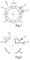
- Fig. 1 shows a schematic representation of an operating device 10 for a motor vehicle in a plan view.
- the operating device 10 serves to operate a functional device of a motor vehicle.
- a functional device may be an air conditioning system, a navigation system, an operating device with associated display, an entertainment system or the like.
- the operating device 10 comprises a turntable which is rotatably mounted on a holding element (not shown here).
- the operating device 10 has a latching device, by which the rotary plate along the direction of rotation r several locking steps are specified.
- the operating device 10 comprises a coding element 12.
- the coding element 12 may be arranged on the turntable.
- the coding element 12 is formed by four permanent magnets 14, which are arranged along the circumferential direction of the operating device 10.
- the operating device 10 comprises a first sensor device 16 and a second sensor device 18, which are formed in the present example as Hall sensors. The distance between the two sensor devices 16, 18 corresponds to half the spatial extent of a permanent magnet 14 along the circumferential direction.
- the coding element 12 is also rotated with the turntable. In the two sensor devices 16, 18, a sensor signal is generated as a function of the rotational position of the turntable.
- the sensor signals have a substantially analogous course, since the transition of the magnetization of the north pole N and the south pole S of the permanent magnets 14 is flowing.
- the sensor signals can be supplied to an analog-to-digital converter, whereby the first sensor device 16, a first actual sensor value x and by the second sensor device 18, a second actual sensor value y is provided.
- Fig. 2 shows an operating device 10 in a further embodiment.
- the coding element 12 is formed by four segments 20 which are arranged along the circumferential direction of the operating device 10.
- a luminous element 22 is arranged in an interior space formed by the segments 20, a luminous element 22 is arranged.
- a first actual sensor value x is provided by the first sensor device 16
- a second actual sensor value y ist is provided by the second sensor device 18.
- Fig. 3 shows in a first graph 24 the time course of the first actual sensor value x is .
- the second graph 26 shows the time course of the second actual sensor value y.
- the time profile of the first actual sensor values x is and the time profile of the second actual sensor values y ist have a substantially sinusoidal profile. It is the timing of the second actual sensor values y is to the curve of the first actual sensor values x is offset.
- Fig. 4 shows a graph 28 in which the second actual sensor values y is plotted as a function of the first actual sensor values x is for predetermined rotational angle ⁇ of the turntable to the holding member. Thereby the actual sensor values is x and y ⁇ coated between two catch steps of the turntable for the predetermined rotation angle be.
- first actual sensor value x is provided by first sensor device 16
- second actual sensor value y ist is provided by second sensor device 18. This is in Fig. 4 indicated by the point 30.
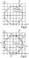
- Fig. 5 2 shows a graph 32 in which second setpoint sensor values y soll are plotted as a function of the first setpoint sensor values x soll for predetermined rotation angles ⁇ of the turntable to the holding element.
- the desired sensor values x soll and y soll are determined, for example, based on measurements with a rotary encoder.
- the setpoint sensor values x soll and y soll may have been determined for predetermined rotation angles ⁇ between two latching stages of the turntable.
- the point 30 is shown, the the current actual sensor values x are and y is in the current rotational position of the turntable.
- the two actual sensor values x and y are now a pair of target sensor values x and y should intended assigned.
- the distance of the pair of actual sensor values x is and y is determined to be the currently closest pair of desired sensor values x soll and y soll .
- the distance of the actual sensor values x and y is to the two pairs target sensor values x should and y is to be determined, the x along the rotational angle ⁇ before and after the currently nearest pair of target sensor values should and y should lie.
- the pair of actual sensor values, x and y is now the pair of target sensor values x and y to assigned to that the smallest distance to the actual sensor values x and y is having.
- the adaptation of the actual sensor values x is and y is is in Fig. 6 clarified.
- a coarse calibration is made.
- the default value is zero for the offset and the value one for the factor.
- the coarse calibration is performed in a rest position of the operating element.
- the coarse calibration is preferably performed when the turntable is in a rotational position in which the actual sensor values is x and y are substantially equal. This is indicated by area 34.
- a factor calibration of the actual sensor values x is and y is .
- the calibration of the factor takes place during operation of the operating device 10.
- the factor for the first actual sensor value x is calibrated. This is done in a rotational position of the turntable, in which the first actual sensor value x is a maximum. This is in Fig. 6 characterized by the area 36. In this area, the rotation angle ⁇ is determined primarily by the first actual sensor value y ist .
- the factor for the second actual sensor value y ist is calibrated. This takes place in a rotational position of the turntable in which the second actual sensor value y ist has a maximum. This is indicated by area 38. In this area, the angle of rotation ⁇ is determined primarily by the first actual sensor value x ist .
- the calibration of the offset for the actual sensor values x is and y is , which is also performed during operation of the operating device 10.
- the offset for the first actual sensor value x is calibrated. This takes place in a rotational position of the turntable in which the first actual sensor value x is at a minimum. This is indicated by area 40. In this area, the angle of rotation ⁇ is determined primarily by the second actual sensor value y ist .
- the offset for the second actual sensor value y ist is calibrated. This takes place in a rotational position of the turntable in which the first actual sensor value x is at a minimum. This is indicated by area 42. In this area, the angle of rotation ⁇ is determined primarily by the second actual sensor value y ist .
Landscapes
- Physics & Mathematics (AREA)
- General Physics & Mathematics (AREA)
- Engineering & Computer Science (AREA)
- General Engineering & Computer Science (AREA)
- Theoretical Computer Science (AREA)
- Human Computer Interaction (AREA)
- Measurement Of Length, Angles, Or The Like Using Electric Or Magnetic Means (AREA)
- Mechanical Control Devices (AREA)
- Length Measuring Devices With Unspecified Measuring Means (AREA)
Description
Die vorliegende Erfindung betrifft ein Verfahren zum Betreiben einer Bedienvorrichtung für ein Kraftfahrzeug. Überdies betrifft die vorliegende Erfindung eine Bedienvorrichtung für ein Kraftfahrzeug.The present invention relates to a method for operating an operating device for a motor vehicle. Moreover, the present invention relates to an operating device for a motor vehicle.
Zur Bedienung von Funktionseinrichtungen eines Kraftfahrzeugs sind entsprechende Bedienvorrichtungen vorgesehen. Diese können einen Drehsteller oder Drehencoder umfassen. Heutige Drehsteller besitzen mechanische Raststellungen, in denen sie entlang ihrer Drehrichtung einrasten. Diese Rastpositionen werden vom Nutzer bzw. von der Bedienperson haptisch wahrgenommen. Derartige manuelle Drehsteller sind seit Jahren millionenfach im Einsatz und werden beispielsweise als Lautstärkesteller, in Klimabedienteilen oder der zentralen Eingabeeinheit im Kraftfahrzeug verwendet. Die Drehsteller weisen meist entsprechende Kodierelemente auf, die mit einem Sensor erfasst werden können. Die Kodierelemente können einen oder mehrere Magnete umfassen, die mit einem Hall-Sensor erfasst werden. Des Weiteren können die Kodierelemente durch elektrische Kontakte gebildet sein, die durch Schleifkontakte erfasst werden. Die Kodierelemente können auch durch entsprechende Aussparung gebildet sein, die mit einem optischen Sensor erfasst werden können.For operating functional devices of a motor vehicle, corresponding operating devices are provided. These may include a turntable or rotary encoder. Today's turntables have mechanical detent positions in which they engage along their direction of rotation. These locking positions are perceived haptically by the user or by the operator. Such manual turntable are millions of years in use and are used for example as a volume control, in climate control parts or the central input unit in the vehicle. The turntables usually have corresponding coding elements that can be detected by a sensor. The coding elements may comprise one or more magnets which are detected by a Hall sensor. Furthermore, the coding elements can be formed by electrical contacts that are detected by sliding contacts. The coding elements can also be formed by corresponding recess, which can be detected by an optical sensor.
In diesem Zusammenhang beschreibt die
Aus der
Des Weiteren ist in der
Zudem beschreibt die
Zudem beschreibt die
Die
Es ist Aufgabe der vorliegenden Erfindung, die Bedienung einer Bedienvorrichtung, insbesondere eines Drehstellers, einfacher und intuitiver zu gestalten.It is an object of the present invention to make the operation of an operating device, in particular a turntable, easier and more intuitive.
Diese Aufgabe wird durch ein Verfahren mit den Merkmalen des Patentanspruchs 1 sowie durch eine Bedienvorrichtung mit den Merkmalen des Patentanspruchs 7 gelöst. Vorteilhafte Weiterbildungen der vorliegenden Erfindung sind in den Unteransprüchen angegeben.This object is achieved by a method having the features of patent claim 1 and by an operating device having the features of patent claim 7. Advantageous developments of the present invention are specified in the subclaims.
Das erfindungsgemäße Verfahren zum Betreiben einer Bedienvorrichtung für ein Kraftfahrzeug, wobei die Bedienvorrichtung einen Drehsteller, der an einem Halteelement drehbar gelagert ist und ein Kodierelement aufweist, umfasst das Erfassen eines ersten Ist-Sensorwerts anhand einer Kodierung des Kodierelements in der aktuellen Drehstellung des Drehstellers, das Bestimmen eines aktuellen Drehwinkels zwischen dem Drehsteller und dem Halteelement auf Grundlage des erfassten ersten Ist-Sensorwerts, das Bereitstellen jeweils zumindest eines Soll-Sensorwerts zu vorbestimmten Drehwinkeln zwischen dem Drehsteller und dem Halteelement, das Zuordnen des erfassten ersten Ist-Sensorwerts zu einem der zumindest einen Soll-Sensorwerte und das Anpassen des ersten Ist-Sensorwerts an dem ihm zugeordneten Soll-Sensorwert für die Bestimmung des aktuellen Drehwinkels.The inventive method for operating an operating device for a motor vehicle, wherein the operating device comprises a turntable which is rotatably mounted on a holding element and having a coding element comprises detecting a first actual sensor value based on a coding of the coding in the current rotational position of the turntable, the Determining a current rotational angle between the rotary actuator and the holding element based on the detected first actual sensor value, providing at least one desired sensor value at predetermined rotational angles between the rotary actuator and the holding element, assigning the detected first actual sensor value to one of the at least one Setpoint sensor values and the adaptation of the first actual sensor value at its assigned setpoint sensor value for the determination of the current rotation angle.
Die Bedienvorrichtung kann im Armaturenbrett oder in der Mittelkonsole des Kraftfahrzeugs angeordnet sein. Das Kraftfahrzeug kann auch mehrere Bedienvorrichtungen umfassen, mit denen Funktionseinrichtungen, wie z.B. eine Klimaanlage, ein Navigationssystem, ein Bedieneinrichtung mit dazugehöriger Anzeige, ein Unterhaltungssystem oder dergleichen angesteuert werden können. Die Bedienvorrichtung umfasst einen Drehsteller, der auch als Dreh-/Drücksteller ausgebildet sein kann. Die Bedienvorrichtung umfasst ein Kodierelement, das beispielsweise an dem Drehsteller angeordnet sein kann. Das Kodierelement kann beispielsweise entlang der Umfangsrichtung des Drehstellers oder einer Welle des Drehstellers angeordnet sein. Zudem umfasst die Bedienvorrichtung eine Sensoreinrichtung, mit der eine Kodierung des Kodierelements erfasst werden kann. Die Sensoreinrichtung kann beispielsweise ortsfest an dem Halteelement oder einem Gehäuse der Bedienvorrichtung angeordnet sein. Durch die Kodierung des Kodierelements wird in der Sensoreinrichtung zumindest ein Ist-Sensorwert erzeugt. Das Kodierelement kann beispielsweise einen oder mehrere Magnete umfassen und die Sensoreinrichtung kann einen Hall-Sensor umfassen. Alternativ dazu kann das Kodierelement Aussparungen oder eine vorbestimmte Geometrie aufweisen, die mit einem optischen Sensor der Sensoreinrichtung abgetastet werden kann. Ebenso ist die Verwendung von Schleifkontakten denkbar.The operating device can be arranged in the dashboard or in the center console of the motor vehicle. The motor vehicle may also comprise a plurality of operating devices with which functional devices, such as an air conditioning system, a navigation system, an operating device with associated display, an entertainment system or the like can be controlled. The operating device comprises a turntable, which can also be designed as a turn / push button. The operating device comprises a coding element, which can be arranged, for example, on the turntable. The coding element can be arranged, for example, along the circumferential direction of the turntable or a shaft of the turntable. In addition, the operating device comprises a sensor device with which a coding of the coding element can be detected. The sensor device can be arranged, for example, stationary on the holding element or a housing of the operating device. By coding the coding element, at least one actual sensor value is generated in the sensor device. The coding element may for example comprise one or more magnets and the sensor device may comprise a Hall sensor. Alternatively, the coding element can have recesses or a predetermined geometry that can be scanned with an optical sensor of the sensor device. Likewise, the use of sliding contacts is conceivable.
Auf einer Speichereinrichtung der Bedienvorrichtung können vier vorgegebene Drehwinkel des Drehstellers zu dem Halteelement Soll-Sensorwerte gespeichert sein. Diese Soll-Sensorwerte können im Vorfeld mit einem Präzisionsdrehgeber für vorbestimmte Winkel entsprechend erfasst worden sein. Die Soll-Sensorwerte können auch vom Hersteller in der Speichereinrichtung abgelegt sein. Im Betrieb der Bedienvorrichtung wird nun ein Ist-Sensorwert anhand der Kodierung des Kodierelements erfasst. Dieser Ist-Sensorwert wird mit den Soll-Sensorwerten vergleichen, die in dem Speicher abgelegt sind. Der Ist-Sensorwert wird nun dem nächstliegenden Soll-Sensorwert zugeordnet. Der Ist-Sensorwert wird nun an dem ihm zugeordneten Soll-Sensorwert angepasst. Somit kann eine entsprechende Kalibrierung des Ist-Sensorwerts fortlaufend im Betrieb der Bedienvorrichtung durchgeführt werden. Durch das Anpassen des Ist-Sensorwerts an den Soll-Sensorwert kann der aktuelle Drehwinkel genauer bestimmt werden.On a storage device of the operating device four predetermined rotation angle of the turntable can be stored to the holding element target sensor values. These desired sensor values may have been detected in advance with a precision rotary encoder for predetermined angles. The desired sensor values can also be stored by the manufacturer in the memory device. During operation of the operating device, an actual sensor value is now detected on the basis of the coding of the coding element. This actual sensor value is compared with the desired sensor values stored in the memory. The actual sensor value is now assigned to the closest desired sensor value. The actual sensor value is now adapted to the setpoint sensor value assigned to it. Thus, a corresponding calibration of the actual sensor value can be carried out continuously in the operation of the operating device. By adjusting the actual sensor value to the desired sensor value, the current rotation angle can be determined more accurately.
Zudem werden dem Drehsteller in entlang seiner Drehrichtung eine Mehrzahl von Raststufen vorgegeben und der erste Ist-Sensorwert wird dem zumindest einen Soll-Sensorwert zwischen zwei der Raststufen zugeordnet. Die Bedienvorrichtung kann eine Rasteinrichtung aufweisen, mit der dem Drehsteller mehrere Raststufen bzw. Rastpositionen entlang seiner Drehrichtung vorgegeben werden. Diese Rastpositionen können mechanisch mit einer Rastkurve oder durch entsprechende Magnete erzeugt werden. Bei der Drehung des Drehstellers rastet dieser in den Rastpositionen ein. Durch die Zuordnung des Ist-Sensorwerts, der anhand der Kodierung des Kodierelements bestimmt wird, zu dem Soll-Sensorwert kann nun auch der Drehwinkel zwischen den einzelnen Raststufen besonders genau erfasst werden. Bei der Bedienvorrichtung sind die diskreten Rastpositionen vorhanden, die durch die haptische Rückmeldung beim Benutzer ein hochwertiges Bediengefühl hervorrufen. Darüber hinaus können leichte Auslenkungen des Drehstellers vor dem Einrasten in die nächste Rastposition mit der Sensoreinrichtung erkannt werden. Dadurch können auf einfache Weise neben den Rastpositionen auch die Zwischenstellungen zwischen den Raststufen mit einer hohen Auflösung erfasst werden und entsprechend weiterverarbeitet werden.In addition, the turntable in accordance with its rotational direction a plurality of latching levels are given and the first actual sensor value is assigned to the at least one target sensor value between two of the latching steps. The operating device may have a latching device with which the turntable a plurality of latching steps or latching positions are set along its direction of rotation. These locking positions can be generated mechanically with a latching curve or by appropriate magnets. When turning the turntable this engages in the locking positions. By assigning the actual sensor value, which is determined on the basis of the coding of the coding element, to the desired sensor value, the angle of rotation between the individual latching steps can now be detected particularly accurately. In the operating device, the discrete locking positions are present, which cause by the haptic feedback to the user a high-quality operating experience. In addition, slight deflections of the turntable can be detected before snapping into the next detent position with the sensor device. As a result, in addition to the latching positions, the intermediate positions between the latching steps can be detected in a simple manner with a high resolution and be further processed accordingly.
In einer Ausführungsform wird der erste Ist-Sensorwert zum Anpassen mit einem Faktor multipliziert und/oder zu dem ersten Ist-Sensorwert wird ein Offset addiert. Um den Ist-Sensorwert im Betrieb der Bedienvorrichtung schrittweise an den jeweiligen Soll-Sensorwert anpassen zu können, kann der jeweilige Ist-Sensorwert mit einem Faktor multipliziert werden. Alternativ oder zusätzlich kann ein Offset für den Ist-Sensorwert bestimmt werden. Somit kann der Ist-Sensorwert besonders einfach an den Soll-Sensorwert angepasst werden.In one embodiment, the first actual sensor value for adaptation is multiplied by a factor and / or an offset is added to the first actual sensor value. In order to be able to adjust the actual sensor value stepwise to the respective desired sensor value during operation of the operating device, the respective actual sensor value can be multiplied by a factor. alternative or additionally, an offset for the actual sensor value can be determined. Thus, the actual sensor value can be adapted particularly easily to the desired sensor value.
Ferner werden anhand der Kodierung des Kodierelements der erste und ein zweiter Ist-Sensorwert für die vorgegebene Drehstellung ermittelt und zu vorbestimmten Drehwinkeln werden jeweils ein erster und ein zweiter Soll-Sensorwert bereitgestellt. Die Bedienvorrichtung kann zwei Sensoreinrichtungen aufweisen, die entlang der Drehrichtung des Drehstellers versetzt zueinander angeordnet sind. Somit wird anhand der Kodierung des Kodierelements mit der ersten Sensoreinrichtung ein erster Ist-Sensorwert und mit der zweiten Sensoreinrichtung ein zweiter Ist-Sensorwert bereitgestellt. In der Speichereinrichtung der Bedienvorrichtung werden für jeden vorbestimmten Drehwinkel des Drehstellers zu dem Halteelement ein erster und ein zweiter Soll-Sensorwert vorgegeben. Durch die Erfassung von zwei Ist-Sensorwerten kann der Drehwinkel zwischen dem Drehsteller und dem Halteelement genauer erfasst werden.Furthermore, based on the coding of the coding element, the first and a second actual sensor value for the predetermined rotational position are determined, and at predetermined rotational angles, a first and a second nominal sensor value are respectively provided. The operating device may have two sensor devices, which are arranged offset from one another along the direction of rotation of the turntable. Thus, based on the coding of the coding element with the first sensor device, a first actual sensor value and with the second sensor device, a second actual sensor value is provided. In the memory device of the operating device, a first and a second setpoint sensor value are predetermined for each predetermined rotation angle of the turntable to the holding element. By detecting two actual sensor values, the angle of rotation between the turntable and the holding element can be detected more accurately.
Des Weiteren wird der erste Ist-Sensorwert dem ersten Soll-Sensorwert zugeordnet und/oder der zweite Ist-Sensorwert wird dem zweiten Soll-Sensorwert zugeordnet. Hierzu kann für jeden vorgegebenen Drehwinkel der dazugehörige Wert des ersten Soll-Sensorwerts gegenüber dem dazugehörigen zweiten Soll-Sensorwert in einem Diagramm aufgetragen werden. Somit kann das Messwertepaar des ersten Ist-Sensorwerts und des zweiten Ist-Sensorwerts dem entsprechenden Paar von erstem Soll-Sensorwert und zweitem Soll-Sensorwert einfach zugeordnet werden.Furthermore, the first actual sensor value is assigned to the first setpoint sensor value and / or the second actual sensor value is assigned to the second setpoint sensor value. For this purpose, the associated value of the first setpoint sensor value with respect to the associated second setpoint sensor value can be plotted in a diagram for each predetermined rotation angle. Thus, the pair of measured values of the first actual sensor value and the second actual sensor value can be simply assigned to the corresponding pair of first desired sensor value and second setpoint sensor value.
Bevorzugt werden der erste Ist-Sensorwert anhand einer Differenz des ersten Ist-Sensorwerts und des ersten Soll-Sensorwerts und/oder der zweite Ist-Sensorwert anhand einer Differenz des zweiten Ist-Sensorwerts und des zweiten Soll-Sensorwerts angepasst. Das Paar der Ist-Sensorwerte wird mit den entsprechenden Paaren der Soll-Sensorwerte verglichen. Dazu wird der Abstand des Paares der Ist-Sensorwerte zu den jeweiligen Paaren der Soll-Sensorwerte bestimmt. Der Abstand berechnet sich aus der Summe des Betrages des ersten Ist-Sensorwerts abzüglich des ersten Soll-Sensorwerts und des Betrags des zweiten Ist-Sensorwerts abzüglich des zweiten Soll-Sensorwerts. Um den Abstand zu bestimmen, können auch andere Verfahren, wie beispielsweise die binäre Suche, verwendet werden. Die Summe der Abstandsquadrate ist ebenso geeignet, wie andere gängige Methoden zur Abstandsquantifizierung. Bei ausreichend häufiger Signalauswertung ergeben sich dann geringste Abstand zwischen dem Paar der Ist-Sensorwerte und dem dazugehörigen Paar der Soll-Sensorwerte. Dabei kann die Abstandsermittlung immer mit den angepassten Ist-Sensorwerten durchgeführt werden. Somit kann der aktuelle Drehwinkel des Drehstellers besonders exakt bestimmt werden. Zudem können Fertigungstoleranzen, Temperatureinflüsse, der Drift der Sensoreinrichtung oder dergleichen ausgeglichen werden. Durch die hier beschriebene Kalibrierung liegen die Ist-Sensorwerte immer sehr dicht an den Soll-Sensorwerten, so dass die Fehler durch das Abstandsverfahren minimiert werden.The first actual sensor value is preferably adjusted on the basis of a difference between the first actual sensor value and the first setpoint sensor value and / or the second actual sensor value on the basis of a difference between the second actual sensor value and the second setpoint sensor value. The pair of actual sensor values is compared with the corresponding pairs of desired sensor values. For this purpose, the distance of the pair of the actual sensor values from the respective pairs of the desired sensor values is determined. The distance is calculated from the sum of the amount of the first actual sensor value minus the first setpoint sensor value and the magnitude of the second actual sensor value minus the second setpoint sensor value. To determine the distance, other methods such as binary search may be used. The sum of the distance squares is also suitable, as are other common methods for distance quantification. If the signal evaluation is sufficiently frequent, then the smallest distance between the pair of the actual sensor values and the associated pair of the setpoint sensor values results. The distance determination can always be carried out with the adjusted actual sensor values. Thus, the current rotation angle of the turntable can be determined very accurately. In addition, manufacturing tolerances, temperature influences, the drift of the sensor device or the like can be compensated. As a result of the calibration described here, the actual sensor values are always very close to the setpoint sensor values, so that the errors due to the distance method are minimized.
In einer weiteren Ausführungsform werden der erste Ist-Sensorwert und/oder der zweite Ist-Sensorwert in einer Drehposition des Drehstellers angepasst, indem der erste Ist-Sensor in einem vorgegebenen Wertebereich liegt. Zunächst wird eine Grobkalibrierung der Bedienvorrichtung durchgeführt. Bei der Grobkalibrierung kann der Sensor insbesondere so angeordnet sein, dass der erste Ist-Sensorwert und der zweite Ist-Sensorwert im Wesentlichen den gleichen Wert aufweisen. Eine derartige Grobkalibrierung kann beispielsweise beim Systemstart durchgeführt werden, um eine Gesamtverstärkung zum Anpassen der Ist-Sensorwerte an die Soll-Sensorwerte zu ermitteln. Die Grobkalibrierung ist besonders effizient, wenn der erste Ist-Sensorwert und der zweite Ist-Sensorwert im Wesentlichen gleiche Werte aufweisen und ein geringer Offset zum Anpassen der Ist-Sensorwerte vorhanden ist. Dabei erfolgt die Grobkalibrierung vor der Benutzung des Drehstellers. Vor der Kalibrierung muss die Abstandsiteration abgeschlossen sein.In a further embodiment, the first actual sensor value and / or the second actual sensor value are adapted in a rotational position of the turntable by the first actual sensor being within a predetermined value range. First, a rough calibration of the operating device is performed. During the coarse calibration, the sensor can be arranged in particular such that the first actual sensor value and the second actual sensor value have substantially the same value. Such a coarse calibration may be performed at system start-up, for example, to determine an overall gain for adjusting the actual sensor values to the desired sensor values. The coarse calibration is particularly efficient when the first actual sensor value and the second actual sensor value are substantially equal and there is a small offset to adjust the actual sensor values. The coarse calibration is done before using the turntable. Prior to calibration, the distance iteration must be completed.
In einer weiteren Ausführungsform wird der Faktor im Betrieb der Bedienvorrichtung in einer Position des Drehstellers bestimmt, in der der erste Ist-Sensorwert oder der zweite Ist-Sensorwert ein Maximum aufweisen. Anschließend an die Grobkalibrierung kann eine entsprechende Feinkalibrierung durchgeführt werden. In dieser wird zunächst der Faktor zum Anpassen der Ist-Sensorwerte an die Soll-Sensorwerte bestimmt. Die Bestimmung des Faktors kann während der Betätigung der Bedienvorrichtung durch den Benutzer erfolgen. In der Nähe eines Maximums des ersten Ist-Sensorwerts wird der Drehwinkel weitgehend von dem zweiten Ist-Sensorwert bestimmt. In diesem Bereich kann der Faktor für den ersten Ist-Sensorwert bestimmt werden. Der Faktor für den zweiten Ist-Sensorwert kann in analoger Weise bestimmt werden.In a further embodiment, the factor during operation of the operating device is determined in a position of the turntable in which the first actual sensor value or the second actual sensor value has a maximum. Subsequent to the coarse calibration, a corresponding fine calibration can be carried out. Initially, the factor for adjusting the actual sensor values to the desired sensor values is determined therein. The determination of the factor can be made during the operation of the operating device by the user. In the vicinity of a maximum of the first actual sensor value, the angle of rotation is largely determined by the second actual sensor value. In this area, the factor for the first actual sensor value can be determined. The factor for the second actual sensor value can be determined in an analogous manner.
In einer weiteren Ausgestaltung wird der Offset im Betrieb der Bedienvorrichtung in einer Position des Drehstellers bestimmt, in der der erste Ist-Sensorwert oder der zweite Ist-Sensorwert ein Minimum aufweist. Die Bestimmung bzw. die Kalibrierung des Offsets erfolgt während der Betätigung der Bedienvorrichtung durch den Bediener. In einem Bereich, in dem der erste Ist-Sensorwert ein Minimum aufweist, wird der Drehwinkel weitgehend vom zweiten Ist-Sensorwert bestimmt. In diesem Bereich kann der Offset für den ersten Ist-Sensorwert bestimmt werden. Der Offset für den zweiten Ist-Sensorwert kann dann in analoger Weise bestimmt werden.In a further embodiment, the offset during operation of the operating device is determined in a position of the turntable in which the first actual sensor value or the second actual sensor value has a minimum. The determination or the calibration of the offset takes place during the operation of the operating device by the operator. In an area in which the first actual sensor value has a minimum, the angle of rotation is largely determined by the second actual sensor value. In this area, the offset for the first actual sensor value can be determined. The offset for the second actual sensor value can then be determined in an analogous manner.
Die erfindungsgemäße Bedienvorrichtung für ein Kraftfahrzeug umfasst einen Drehsteller, der an einem Halteelement drehbar gelagert ist, ein Kodierelement, zumindest eine Sensoreinrichtung zum Erfassen eines ersten Ist-Sensorwerts anhand einer Kodierung des Kodierelements in der aktuellen Drehstellung des Drehstellers und eine Recheneinrichtung zum Bestimmen eines aktuellen Drehwinkels zwischen dem Drehsteller und dem Halteelement auf Grundlage des erfassten ersten Ist-Sensorwerts, wobei die Bedienvorrichtung eine Speichereinrichtung zum Bereitstellen jeweils zumindest eines Soll-Sensorwerts zu vorbestimmten Drehwinkeln zwischen dem Drehsteller und dem Halteelement aufweist und die Recheneinrichtung dazu ausgebildet ist, den erfassten ersten Ist-Sensorwert einem der zumindest einen Soll-Sensorwerte zuzuordnen und den ersten Ist-Sensorwert für die Bestimmung des aktuellen Drehwinkels an dem ihm zugeordneten Soll-Sensorwert anzupassen.The operating device according to the invention for a motor vehicle comprises a turntable which is rotatably mounted on a holding element, a coding element, at least one sensor device for detecting a first actual sensor value based on a coding of the coding element in the current rotational position of the turntable and a computing device for determining a current angle of rotation between the turntable and the holding element on the basis of the detected first actual sensor value, wherein the operating device has a storage device for providing in each case at least one desired sensor value at predetermined rotational angles between the turntable and the holding element and the calculating device is designed to detect the detected first actual value. Assign sensor value of the at least one setpoint sensor values and adjust the first actual sensor value for the determination of the current rotation angle at its associated target sensor value.
Die zuvor im Zusammenhang mit dem erfindungsgemäßen Verfahren beschriebenen Vorteile und Weiterbildungen können in gleicher Weise auf die erfindungsgemäße Bedienvorrichtung übertragen werden.The advantages and further developments described above in connection with the method according to the invention can be transferred in the same way to the operating device according to the invention.
Die vorliegende Erfindung wird nun anhand der beigefügten Zeichnungen näher erläutert. Dabei zeigen:
-
Fig. 1 eine Bedienvorrichtung für ein Kraftfahrzeug in einer schematischen Darstellung; -
Fig. 2 eine Bedienvorrichtung für ein Kraftfahrzeug in einer weiteren Ausführungsform; -
Fig.3 die Signale vom ersten Ist-Sensorwerten und zweiten Ist-Sensorwerten in Abhängigkeit von der Zeit; -
Fig. 4 ein Diagramm, in dem die ersten Ist-Sensorwerte über die zweiten Ist-Sensorwerte aufgetragen sind; -
Fig.5 in dem die ersten Soll-Sensorwerte über die zweiten Soll-Sensorwerte aufgetragen sind; und -
Fig. 6 ein Diagramm gemäßFig. 5 in einer weiteren Ausführungsform. Die nachfolgend näher geschilderten Ausführungsbeispiele stellen bevorzugte Ausführungsformen der vorliegenden Erfindung dar.
-
Fig. 1 an operating device for a motor vehicle in a schematic representation; -
Fig. 2 an operating device for a motor vehicle in a further embodiment; -
Figure 3 the signals from the first actual sensor values and second actual sensor values as a function of time; -
Fig. 4 a diagram in which the first actual sensor values are plotted against the second actual sensor values; -
Figure 5 in which the first setpoint sensor values are plotted against the second setpoint sensor values; and -
Fig. 6 a diagram according toFig. 5 in a further embodiment. The embodiments described in more detail below represent preferred embodiments of the present invention.
Des Weiteren umfasst die Bedienvorrichtung 10 ein Kodierelement 12. Das Kodierelement 12 kann an dem Drehsteller angeordnet sein. Vorliegend ist das Kodierelement 12 durch vier Permanentmagnete 14 gebildet, die entlang der Umfangsrichtung der Bedienvorrichtung 10 angeordnet sind. Des Weiteren umfasst die Bedienvorrichtung 10 eine erste Sensoreinrichtung 16 und eine zweite Sensoreinrichtung 18, die im vorliegenden Beispiel als Hall-Sensoren ausgebildet sind. Der Abstand zwischen den beiden Sensoreinrichtungen 16, 18 entspricht die Hälfte der räumlichen Ausdehnung eines Permanentmagnets 14 entlang der Umfangsrichtung. Wenn der Drehsteller durch eine Bedienperson gedreht wird, wird auch das Kodierelement 12 mit dem Drehsteller gedreht. In den beiden Sensoreinrichtungen 16, 18 wird in Abhängigkeit von der Drehstellung des Drehstellers ein Sensorsignal erzeugt. Die Sensorsignale weisen einen im Wesentlichen analogen Verlauf auf, da der Übergang der Magnetisierung der Nordpole N und der Südpole S der Permanentmagnete 14 fließend ist. Die Sensorsignale können einem Analog-Digital-Wandler zugeführt werden, wodurch durch die erste Sensoreinrichtung 16 ein erster Ist-Sensorwert xist und durch die zweite Sensoreinrichtung 18 ein zweiter Ist-Sensorwert yist bereitgestellt wird.Furthermore, the operating
Die beiden Ist-Sensorwerte xist und yist werden nun einem Paar von Soll-Sensorwerten xsoll und ysoll zugeordnet. Dazu wird der Abstand des Paars der Ist-Sensorwerte xist und yist zu dem momentan nächstliegenden Paar von Soll-Sensorwerten xsoll und ysoll bestimmt. Dabei ist es auch vorgesehen, dass der Abstand der Ist-Sensorwerte xist und yist zu dem beiden Paaren Soll-Sensorwerten xsoll und ysoll bestimmt wird, die entlang des Drehwinkels α vor und hinter dem momentan nächstliegenden Paar von Soll-Sensorwerten xsoll und ysoll liegen. Der Abstand kann nach folgender Formel berechnet werden: ![]()
![]()
Das Paar von Ist-Sensorwerte xist und yist wird nun dem Paar von Soll-Sensorwerten xsoll und ysoll zugeordnet, dass den geringsten Abstand zu den Ist-Sensorwerte xist und yist aufweist. Zum Anpassen der Ist-Sensorwerte xist und yist können die Ist-Sensorwerte xist und yist mit einem Faktor multipliziert werden. Alternativ oder zusätzlich kann zu den Ist-Sensorwerte xist und yist ein Offset addiert werden.The pair of actual sensor values, x and y is now the pair of target sensor values x and y to assigned to that the smallest distance to the actual sensor values x and y is having. To adjust the actual sensor values x is and y is the actual sensor values x is and y is to be multiplied by a factor. Alternatively or in addition to the actual sensor values x and y, an offset is to be added.
Die Anpassung der Ist-Sensorwerte xist und yist ist in ![]()
![]()
Anschließend erfolgt eine Faktorkalibrierung der Ist-Sensorwerte xist und yist. Die Kalibrierung des Faktors erfolgt im Betrieb der Bedienvorrichtung 10. Zunächst wird der Faktor für den ersten Ist-Sensorwert xist kalibriert. Dies erfolgt in einer Drehstellung des Drehstellers, in der der erste Ist-Sensorwert xist ein Maximum aufweist. Dies ist in ![]()
![]()
Anschließend wird der Faktor für den zweiten Ist-Sensorwert yist kalibriert. Dies erfolgt in einer Drehstellung des Drehstellers, in der der zweite Ist-Sensorwert yist ein Maximum aufweist. Dies ist durch den Bereich 38 gekennzeichnet. In diesem Bereich wird der Drehwinkel α vor allem durch den ersten Ist-Sensorwert xist bestimmt.Subsequently, the factor for the second actual sensor value y ist is calibrated. This takes place in a rotational position of the turntable in which the second actual sensor value y ist has a maximum. This is indicated by
Zudem erfolgt die Kalibrierung des Offsets für die Ist-Sensorwerte xist und yist, die auch im Betrieb der Bedienvorrichtung 10 vorgenommen wird. Zunächst wird der Offset für den ersten Ist-Sensorwert xist kalibriert. Dies erfolgt in einer Drehstellung des Drehstellers, in der der erste Ist-Sensorwert xist ein Minimum aufweist. Dies ist durch den Bereich 40 gekennzeichnet. In diesem Bereich wird der Drehwinkel α vor allem durch den zweiten Ist-Sensorwert yist bestimmt. Der Offset berechnet sich nach folgender Formel: ![]()
![]()
Anschließend wird der Offset für den zweiten Ist-Sensorwert yist kalibriert. Dies erfolgt in einer Drehstellung des Drehstellers, in der der erste Ist-Sensorwert xist ein Minimum aufweist. Dies ist durch den Bereich 42 gekennzeichnet. In diesem Bereich wird der Drehwinkel α vor allem durch den zweiten Ist-Sensorwert yist bestimmt.Subsequently, the offset for the second actual sensor value y ist is calibrated. This takes place in a rotational position of the turntable in which the first actual sensor value x is at a minimum. This is indicated by
Claims (7)
- Method for operating an operating device (10) for a motor vehicle, the operating device (10) having a rotary actuator, which is mounted rotatably on a holding element, and a coding element (12), having the steps:- detecting a first actual sensor value (xist) and a second actual sensor value (yist) with the aid of a coding of the coding element (12) in the current rotational position of the rotary actuator,- determining a current rotation angle between the rotary actuator and the holding element on the basis of the detected first actual sensor value (xist) and the second actual sensor value (yist),- providing a first setpoint sensor value (xsoll) and a second setpoint sensor value (ysoll) for predetermined rotational angles (α) between the rotary actuator and the holding element,- assigning the detected first actual sensor value (xist) to the first setpoint sensor value (xsoll) and the detected second actual sensor value (yist) to the second setpoint sensor value (ysoll),wherein,- in order to determine the current rotational angle, the first actual sensor value (xist) is adapted to the first setpoint sensor value (xsoll) assigned to it and the second actual sensor value (yist) is adapted to the second setpoint sensor value (ysoll) assigned to it,- the first actual sensor value (xist) is detected with a first sensor apparatus (16) and the second actual sensor value (yist) is detected with a second sensor apparatus (18), and- a multiplicity of latching stages are defined for the rotary actuator along its rotation direction (r), and the first actual sensor value (xist) is assigned to the first setpoint sensor value (xsoll) and the second actual sensor value (yist) is assigned to the second setpoint sensor value (ysoll) between two of the latching stages.
- Method according to claim 1,
characterised in that,
for the adaptation, the first actual sensor value (xist) and the second actual sensor value (yist) are multiplied by a factor and/or an offset is added to the first actual sensor value (xist) and to the second actual sensor value (yist). - Method according to claim 1 or 2,
characterised in that
a difference between the first actual sensor value (xist) and the first setpoint sensor value (xsoll) is determined in order to adapt the first actual sensor value (xist), and/or a difference between the second actual sensor value (yist) and the second setpoint sensor value (ysoll) is determined in order to adapt the second actual sensor value (yist). - Method according to any one of the preceding claims,
characterised in that
the first actual sensor value (xist) and/or the second actual sensor value (yist) are adapted in a rotational position of the rotary actuator in which the first actual sensor value (xist) and the second actual sensor value (yist) lie in a predetermined value range. - Method according to any one of claims 2 to 4,
characterised in that
the factor is determined during operation of the operating device in a position of the rotary actuator in which the first actual sensor value (xist) or the second actual sensor value (yist) has a maximum. - Method according to any one of claims 2 to 5,
characterised in that
the offset is determined during operation of the operating device in a position of the rotary actuator in which the first actual sensor value (xist) or the second actual sensor value (yist) has a minimum. - Operating device (10) for a motor vehicle, having,- a rotary actuator, which is mounted rotatably on a holding element,- a coding element (12),- a first sensor apparatus (16) for detecting a first actual sensor value (xist) and with the aid of a coding of the coding element (12) in the current rotational position of the rotary actuator,- a second sensor apparatus (18) for detecting a second actual sensor value (yist) with the aid of the coding of the coding element (12) in the current rotational position of the rotary actuator, and- a computing apparatus for determining a current rotation angle between the rotary actuator and the holding element on the basis of the detected first actual sensor value (xist) and the detected second actual sensor value (yist),- the operating device has a memory apparatus for providing a first setpoint sensor value (xsoll) and a second setpoint sensor value (ysoll) for predetermined rotational angles (α) between the rotary actuator and the holding element,- the computing apparatus is configured in order to assign the detected first actual sensor value (xist) to the first setpoint sensor value (xsoll) and the detected second actual sensor value (yist) to the second setpoint sensor value (ysoll) and, in order to determine the current rotation angle, to adapt the first actual sensor value (xist) to the first setpoint sensor value (xsoll) assigned to it and the second actual sensor value (yist) to the second setpoint sensor value (ysoll) assigned to it, wherein- a multiplicity of latching stages are defined for the rotary actuator along its rotation direction (r), and the computing apparatus is configured in order to assign the first actual sensor value (xist) to the first setpoint sensor value (xsoll) and the second actual sensor value (yist) to the second setpoint sensor value (ysoll) between two of the latching stages.
Applications Claiming Priority (2)
| Application Number | Priority Date | Filing Date | Title |
|---|---|---|---|
| DE102012019995.3A DE102012019995B4 (en) | 2012-10-12 | 2012-10-12 | Method for operating an operating device for a motor vehicle and operating device |
| PCT/EP2013/001732 WO2014056556A1 (en) | 2012-10-12 | 2013-06-12 | Method for operating an operating device for a motor vehicle |
Publications (2)
| Publication Number | Publication Date |
|---|---|
| EP2906910A1 EP2906910A1 (en) | 2015-08-19 |
| EP2906910B1 true EP2906910B1 (en) | 2017-04-26 |
Family
ID=48669847
Family Applications (1)
| Application Number | Title | Priority Date | Filing Date |
|---|---|---|---|
| EP13730111.5A Not-in-force EP2906910B1 (en) | 2012-10-12 | 2013-06-12 | Method for operating an operating device for a motor vehicle |
Country Status (5)
| Country | Link |
|---|---|
| US (1) | US9507444B2 (en) |
| EP (1) | EP2906910B1 (en) |
| CN (1) | CN104220845B (en) |
| DE (1) | DE102012019995B4 (en) |
| WO (1) | WO2014056556A1 (en) |
Families Citing this family (2)
| Publication number | Priority date | Publication date | Assignee | Title |
|---|---|---|---|---|
| DE102012019995B4 (en) | 2012-10-12 | 2015-02-19 | Audi Ag | Method for operating an operating device for a motor vehicle and operating device |
| DE102013014792A1 (en) * | 2013-09-09 | 2015-03-12 | Leopold Kostal Gmbh & Co. Kg | Screen-based vehicle operating system |
Citations (1)
| Publication number | Priority date | Publication date | Assignee | Title |
|---|---|---|---|---|
| DE19915988A1 (en) * | 1999-04-09 | 2000-10-12 | Pierburg Ag | Measuring device for determining the position of an actuator |
Family Cites Families (14)
| Publication number | Priority date | Publication date | Assignee | Title |
|---|---|---|---|---|
| DE4438880A1 (en) | 1994-10-31 | 1996-05-02 | Elobau Elektrobauelemente Gmbh | Rotation angle sensor with housing and rotating body forming electric coupling |
| DE10018795A1 (en) | 2000-04-15 | 2001-10-25 | Bosch Gmbh Robert | Operating device |
| EP1696203A4 (en) * | 2003-11-28 | 2008-02-20 | Valeo Thermal Sys Japan Co | Rotary switch mechanism |
| EP1674831A1 (en) * | 2004-12-23 | 2006-06-28 | Carl Freudenberg KG | Method for the transmission of angle information and apparatus implementing the method |
| DE102005055307A1 (en) * | 2005-07-01 | 2007-01-11 | Preh Gmbh | Rotary actuator with incremental rotary encoder |
| DE102006060808A1 (en) * | 2006-12-21 | 2008-06-26 | Siemens Ag | Angle sensor has Hall element fixed in magnetic field region of annular magnet for producing digital signal dependent on rotary position of the magnet, magnetoresistive sensor element and evaluation unit |
| DE102008000943B4 (en) | 2008-04-02 | 2015-02-19 | Zf Friedrichshafen Ag | Diagnostic Hall sensor and method for functional diagnosis of a Hall sensor device |
| DE102008041649A1 (en) * | 2008-08-28 | 2010-03-04 | Visteon Global Technologies, Inc., Van Buren Township | Screen-based vehicle operating system |
| DE102009028170A1 (en) * | 2009-07-31 | 2011-02-10 | Robert Bosch Gmbh | Commutated electric drive and method for controlling a commutated electric motor |
| DE102009051730A1 (en) * | 2009-11-03 | 2011-05-05 | Bayerische Motoren Werke Aktiengesellschaft | Multifunctional-operating device for motor vehicle, has hall sensor arranged on board and working together with magnet in contactless manner, where board is provided for electrically and/or electronically controlling device of vehicle |
| FR2958761B1 (en) | 2010-04-12 | 2012-03-23 | Delphi Tech Inc | HOLOGRAPHIC INDEXING AND DISPLAY SYSTEM FOR INTERFACE |
| US8866643B2 (en) * | 2010-09-07 | 2014-10-21 | Alps Electric Co., Ltd. | Rotation input device |
| DE102010056271B4 (en) | 2010-12-24 | 2018-09-20 | Paragon Ag | Sensor arrangement for detecting both the axial and the rotational position of a longitudinally displaceable and rotatable shaft |
| DE102012019995B4 (en) | 2012-10-12 | 2015-02-19 | Audi Ag | Method for operating an operating device for a motor vehicle and operating device |
-
2012
- 2012-10-12 DE DE102012019995.3A patent/DE102012019995B4/en not_active Expired - Fee Related
-
2013
- 2013-06-12 EP EP13730111.5A patent/EP2906910B1/en not_active Not-in-force
- 2013-06-12 CN CN201380019545.0A patent/CN104220845B/en not_active Expired - Fee Related
- 2013-06-12 WO PCT/EP2013/001732 patent/WO2014056556A1/en active Application Filing
- 2013-06-12 US US14/435,277 patent/US9507444B2/en active Active
Patent Citations (1)
| Publication number | Priority date | Publication date | Assignee | Title |
|---|---|---|---|---|
| DE19915988A1 (en) * | 1999-04-09 | 2000-10-12 | Pierburg Ag | Measuring device for determining the position of an actuator |
Also Published As
| Publication number | Publication date |
|---|---|
| CN104220845B (en) | 2017-05-03 |
| CN104220845A (en) | 2014-12-17 |
| US20150253876A1 (en) | 2015-09-10 |
| EP2906910A1 (en) | 2015-08-19 |
| DE102012019995B4 (en) | 2015-02-19 |
| DE102012019995A1 (en) | 2014-04-17 |
| WO2014056556A1 (en) | 2014-04-17 |
| US9507444B2 (en) | 2016-11-29 |
Similar Documents
| Publication | Publication Date | Title |
|---|---|---|
| AT510377B1 (en) | METHOD AND EMBODIMENTS FOR THE ABSOLUTE POSITION DETERMINATION BY MEANS OF TWO HALL SENSORS | |
| EP2820382B1 (en) | Apparatus and method for the redundant, absolute position determination of a movable body | |
| EP2304274B1 (en) | Method for calibrating a position sensor in a motor vehicle gear | |
| DE102017222674A1 (en) | displacement sensor | |
| DE102012205902A1 (en) | Position sensor for non-contact measurement of a position by means of a plurality of magnetic field sensors arranged in series | |
| EP0990120A1 (en) | Angle sensor and a method for determining an angle | |
| WO2013139520A1 (en) | Magnetic field sensor, actuating device and method for determining a relative position | |
| EP2225142A1 (en) | Absolute measurement steering angle sensor arrangement | |
| WO2014166689A1 (en) | Magnetic field sensor apparatus, operating apparatus and method for determining a relative position | |
| DE102012109787A1 (en) | Steering angle sensor for motor vehicles | |
| WO2000079220A1 (en) | Method for compensating the offset of angle sensors | |
| DE112018003012T5 (en) | Position sensor | |
| EP2891024B1 (en) | Control unit for a functional device in a motor vehicle | |
| EP2906910B1 (en) | Method for operating an operating device for a motor vehicle | |
| DE112018003016T5 (en) | POSITION SENSOR | |
| EP2385353A1 (en) | Magnetic encoder, in particular for use in a measurement system for measuring the absolute position of a body which can be pushed or rotated relative to a reference body and measurement system | |
| EP1308698A2 (en) | Method for offset compensation of angle sensors | |
| DE102004001570B4 (en) | Measuring method and measuring device for carrying out the measuring method | |
| DE102010019484B9 (en) | Sensor arrangement and method for operating a sensor arrangement | |
| EP3645980B1 (en) | Method and device for adjusting the position of a magnet relative to a gmr sensor | |
| WO2016150616A1 (en) | Sensor arrangement for measuring the rate of rotation of a rotating component | |
| DE102017211994B4 (en) | Sensor unit and arrangement for detecting the position of a component | |
| EP2732244B1 (en) | Position detection device | |
| DE102012203158A1 (en) | Device for sensor system for contactless detection of absolute position of rotatable element, has magneto-sensitive sensors that detect axial component of magnetic field, where absolute position is recognized over certain angular range | |
| DE102013225935A1 (en) | Sensor e.g. steering angle sensor, for detecting angle position of measured object e.g. steering wheel of vehicle, has detector that is fixed to rotary case, for outputting measuring signal depending on axial position of sensor element |
Legal Events
| Date | Code | Title | Description |
|---|---|---|---|
| PUAI | Public reference made under article 153(3) epc to a published international application that has entered the european phase |
Free format text: ORIGINAL CODE: 0009012 |
|
| 17P | Request for examination filed |
Effective date: 20150512 |
|
| AK | Designated contracting states |
Kind code of ref document: A1 Designated state(s): AL AT BE BG CH CY CZ DE DK EE ES FI FR GB GR HR HU IE IS IT LI LT LU LV MC MK MT NL NO PL PT RO RS SE SI SK SM TR |
|
| AX | Request for extension of the european patent |
Extension state: BA ME |
|
| RIN1 | Information on inventor provided before grant (corrected) |
Inventor name: KRUG, JOACHIM Inventor name: MAIWALD, STEFAN |
|
| DAX | Request for extension of the european patent (deleted) | ||
| 17Q | First examination report despatched |
Effective date: 20160429 |
|
| GRAP | Despatch of communication of intention to grant a patent |
Free format text: ORIGINAL CODE: EPIDOSNIGR1 |
|
| RIC1 | Information provided on ipc code assigned before grant |
Ipc: G01D 5/347 20060101ALI20170130BHEP Ipc: G01D 5/245 20060101AFI20170130BHEP Ipc: G06F 3/0362 20130101ALI20170130BHEP |
|
| GRAS | Grant fee paid |
Free format text: ORIGINAL CODE: EPIDOSNIGR3 |
|
| INTG | Intention to grant announced |
Effective date: 20170221 |
|
| GRAA | (expected) grant |
Free format text: ORIGINAL CODE: 0009210 |
|
| AK | Designated contracting states |
Kind code of ref document: B1 Designated state(s): AL AT BE BG CH CY CZ DE DK EE ES FI FR GB GR HR HU IE IS IT LI LT LU LV MC MK MT NL NO PL PT RO RS SE SI SK SM TR |
|
| REG | Reference to a national code |
Ref country code: GB Ref legal event code: FG4D Free format text: NOT ENGLISH |
|
| REG | Reference to a national code |
Ref country code: CH Ref legal event code: EP |
|
| REG | Reference to a national code |
Ref country code: AT Ref legal event code: REF Ref document number: 888286 Country of ref document: AT Kind code of ref document: T Effective date: 20170515 |
|
| REG | Reference to a national code |
Ref country code: IE Ref legal event code: FG4D Free format text: LANGUAGE OF EP DOCUMENT: GERMAN |
|
| REG | Reference to a national code |
Ref country code: DE Ref legal event code: R096 Ref document number: 502013007081 Country of ref document: DE |
|
| REG | Reference to a national code |
Ref country code: FR Ref legal event code: PLFP Year of fee payment: 5 |
|
| REG | Reference to a national code |
Ref country code: NL Ref legal event code: MP Effective date: 20170426 |
|
| REG | Reference to a national code |
Ref country code: LT Ref legal event code: MG4D |
|
| PG25 | Lapsed in a contracting state [announced via postgrant information from national office to epo] |
Ref country code: NL Free format text: LAPSE BECAUSE OF FAILURE TO SUBMIT A TRANSLATION OF THE DESCRIPTION OR TO PAY THE FEE WITHIN THE PRESCRIBED TIME-LIMIT Effective date: 20170426 |
|
| PG25 | Lapsed in a contracting state [announced via postgrant information from national office to epo] |
Ref country code: ES Free format text: LAPSE BECAUSE OF FAILURE TO SUBMIT A TRANSLATION OF THE DESCRIPTION OR TO PAY THE FEE WITHIN THE PRESCRIBED TIME-LIMIT Effective date: 20170426 Ref country code: HR Free format text: LAPSE BECAUSE OF FAILURE TO SUBMIT A TRANSLATION OF THE DESCRIPTION OR TO PAY THE FEE WITHIN THE PRESCRIBED TIME-LIMIT Effective date: 20170426 Ref country code: LT Free format text: LAPSE BECAUSE OF FAILURE TO SUBMIT A TRANSLATION OF THE DESCRIPTION OR TO PAY THE FEE WITHIN THE PRESCRIBED TIME-LIMIT Effective date: 20170426 Ref country code: FI Free format text: LAPSE BECAUSE OF FAILURE TO SUBMIT A TRANSLATION OF THE DESCRIPTION OR TO PAY THE FEE WITHIN THE PRESCRIBED TIME-LIMIT Effective date: 20170426 Ref country code: GR Free format text: LAPSE BECAUSE OF FAILURE TO SUBMIT A TRANSLATION OF THE DESCRIPTION OR TO PAY THE FEE WITHIN THE PRESCRIBED TIME-LIMIT Effective date: 20170727 Ref country code: NO Free format text: LAPSE BECAUSE OF FAILURE TO SUBMIT A TRANSLATION OF THE DESCRIPTION OR TO PAY THE FEE WITHIN THE PRESCRIBED TIME-LIMIT Effective date: 20170726 |
|
| PG25 | Lapsed in a contracting state [announced via postgrant information from national office to epo] |
Ref country code: SE Free format text: LAPSE BECAUSE OF FAILURE TO SUBMIT A TRANSLATION OF THE DESCRIPTION OR TO PAY THE FEE WITHIN THE PRESCRIBED TIME-LIMIT Effective date: 20170426 Ref country code: BG Free format text: LAPSE BECAUSE OF FAILURE TO SUBMIT A TRANSLATION OF THE DESCRIPTION OR TO PAY THE FEE WITHIN THE PRESCRIBED TIME-LIMIT Effective date: 20170726 Ref country code: IS Free format text: LAPSE BECAUSE OF FAILURE TO SUBMIT A TRANSLATION OF THE DESCRIPTION OR TO PAY THE FEE WITHIN THE PRESCRIBED TIME-LIMIT Effective date: 20170826 Ref country code: PL Free format text: LAPSE BECAUSE OF FAILURE TO SUBMIT A TRANSLATION OF THE DESCRIPTION OR TO PAY THE FEE WITHIN THE PRESCRIBED TIME-LIMIT Effective date: 20170426 Ref country code: LV Free format text: LAPSE BECAUSE OF FAILURE TO SUBMIT A TRANSLATION OF THE DESCRIPTION OR TO PAY THE FEE WITHIN THE PRESCRIBED TIME-LIMIT Effective date: 20170426 Ref country code: RS Free format text: LAPSE BECAUSE OF FAILURE TO SUBMIT A TRANSLATION OF THE DESCRIPTION OR TO PAY THE FEE WITHIN THE PRESCRIBED TIME-LIMIT Effective date: 20170426 |
|
| REG | Reference to a national code |
Ref country code: DE Ref legal event code: R097 Ref document number: 502013007081 Country of ref document: DE |
|
| PG25 | Lapsed in a contracting state [announced via postgrant information from national office to epo] |
Ref country code: CZ Free format text: LAPSE BECAUSE OF FAILURE TO SUBMIT A TRANSLATION OF THE DESCRIPTION OR TO PAY THE FEE WITHIN THE PRESCRIBED TIME-LIMIT Effective date: 20170426 Ref country code: MC Free format text: LAPSE BECAUSE OF FAILURE TO SUBMIT A TRANSLATION OF THE DESCRIPTION OR TO PAY THE FEE WITHIN THE PRESCRIBED TIME-LIMIT Effective date: 20170426 Ref country code: RO Free format text: LAPSE BECAUSE OF FAILURE TO SUBMIT A TRANSLATION OF THE DESCRIPTION OR TO PAY THE FEE WITHIN THE PRESCRIBED TIME-LIMIT Effective date: 20170426 Ref country code: EE Free format text: LAPSE BECAUSE OF FAILURE TO SUBMIT A TRANSLATION OF THE DESCRIPTION OR TO PAY THE FEE WITHIN THE PRESCRIBED TIME-LIMIT Effective date: 20170426 Ref country code: DK Free format text: LAPSE BECAUSE OF FAILURE TO SUBMIT A TRANSLATION OF THE DESCRIPTION OR TO PAY THE FEE WITHIN THE PRESCRIBED TIME-LIMIT Effective date: 20170426 Ref country code: SK Free format text: LAPSE BECAUSE OF FAILURE TO SUBMIT A TRANSLATION OF THE DESCRIPTION OR TO PAY THE FEE WITHIN THE PRESCRIBED TIME-LIMIT Effective date: 20170426 |
|
| REG | Reference to a national code |
Ref country code: CH Ref legal event code: PL |
|
| PG25 | Lapsed in a contracting state [announced via postgrant information from national office to epo] |
Ref country code: IT Free format text: LAPSE BECAUSE OF FAILURE TO SUBMIT A TRANSLATION OF THE DESCRIPTION OR TO PAY THE FEE WITHIN THE PRESCRIBED TIME-LIMIT Effective date: 20170426 Ref country code: SM Free format text: LAPSE BECAUSE OF FAILURE TO SUBMIT A TRANSLATION OF THE DESCRIPTION OR TO PAY THE FEE WITHIN THE PRESCRIBED TIME-LIMIT Effective date: 20170426 |
|
| PLBE | No opposition filed within time limit |
Free format text: ORIGINAL CODE: 0009261 |
|
| STAA | Information on the status of an ep patent application or granted ep patent |
Free format text: STATUS: NO OPPOSITION FILED WITHIN TIME LIMIT |
|
| REG | Reference to a national code |
Ref country code: IE Ref legal event code: MM4A |
|
| 26N | No opposition filed |
Effective date: 20180129 |
|
| PG25 | Lapsed in a contracting state [announced via postgrant information from national office to epo] |
Ref country code: LU Free format text: LAPSE BECAUSE OF NON-PAYMENT OF DUE FEES Effective date: 20170612 Ref country code: IE Free format text: LAPSE BECAUSE OF NON-PAYMENT OF DUE FEES Effective date: 20170612 Ref country code: CH Free format text: LAPSE BECAUSE OF NON-PAYMENT OF DUE FEES Effective date: 20170630 Ref country code: LI Free format text: LAPSE BECAUSE OF NON-PAYMENT OF DUE FEES Effective date: 20170630 |
|
| PG25 | Lapsed in a contracting state [announced via postgrant information from national office to epo] |
Ref country code: SI Free format text: LAPSE BECAUSE OF FAILURE TO SUBMIT A TRANSLATION OF THE DESCRIPTION OR TO PAY THE FEE WITHIN THE PRESCRIBED TIME-LIMIT Effective date: 20170426 |
|
| REG | Reference to a national code |
Ref country code: BE Ref legal event code: MM Effective date: 20170630 |
|
| REG | Reference to a national code |
Ref country code: FR Ref legal event code: PLFP Year of fee payment: 6 |
|
| PG25 | Lapsed in a contracting state [announced via postgrant information from national office to epo] |
Ref country code: BE Free format text: LAPSE BECAUSE OF NON-PAYMENT OF DUE FEES Effective date: 20170630 |
|
| PG25 | Lapsed in a contracting state [announced via postgrant information from national office to epo] |
Ref country code: MT Free format text: LAPSE BECAUSE OF FAILURE TO SUBMIT A TRANSLATION OF THE DESCRIPTION OR TO PAY THE FEE WITHIN THE PRESCRIBED TIME-LIMIT Effective date: 20170426 |
|
| PG25 | Lapsed in a contracting state [announced via postgrant information from national office to epo] |
Ref country code: HU Free format text: LAPSE BECAUSE OF FAILURE TO SUBMIT A TRANSLATION OF THE DESCRIPTION OR TO PAY THE FEE WITHIN THE PRESCRIBED TIME-LIMIT; INVALID AB INITIO Effective date: 20130612 |
|
| REG | Reference to a national code |
Ref country code: AT Ref legal event code: MM01 Ref document number: 888286 Country of ref document: AT Kind code of ref document: T Effective date: 20180612 |
|
| PG25 | Lapsed in a contracting state [announced via postgrant information from national office to epo] |
Ref country code: CY Free format text: LAPSE BECAUSE OF FAILURE TO SUBMIT A TRANSLATION OF THE DESCRIPTION OR TO PAY THE FEE WITHIN THE PRESCRIBED TIME-LIMIT Effective date: 20170426 |
|
| PG25 | Lapsed in a contracting state [announced via postgrant information from national office to epo] |
Ref country code: MK Free format text: LAPSE BECAUSE OF FAILURE TO SUBMIT A TRANSLATION OF THE DESCRIPTION OR TO PAY THE FEE WITHIN THE PRESCRIBED TIME-LIMIT Effective date: 20170426 |
|
| PG25 | Lapsed in a contracting state [announced via postgrant information from national office to epo] |
Ref country code: AT Free format text: LAPSE BECAUSE OF NON-PAYMENT OF DUE FEES Effective date: 20180612 |
|
| PG25 | Lapsed in a contracting state [announced via postgrant information from national office to epo] |
Ref country code: TR Free format text: LAPSE BECAUSE OF FAILURE TO SUBMIT A TRANSLATION OF THE DESCRIPTION OR TO PAY THE FEE WITHIN THE PRESCRIBED TIME-LIMIT Effective date: 20170426 |
|
| PG25 | Lapsed in a contracting state [announced via postgrant information from national office to epo] |
Ref country code: PT Free format text: LAPSE BECAUSE OF FAILURE TO SUBMIT A TRANSLATION OF THE DESCRIPTION OR TO PAY THE FEE WITHIN THE PRESCRIBED TIME-LIMIT Effective date: 20170426 |
|
| PG25 | Lapsed in a contracting state [announced via postgrant information from national office to epo] |
Ref country code: AL Free format text: LAPSE BECAUSE OF FAILURE TO SUBMIT A TRANSLATION OF THE DESCRIPTION OR TO PAY THE FEE WITHIN THE PRESCRIBED TIME-LIMIT Effective date: 20170426 |
|
| PGFP | Annual fee paid to national office [announced via postgrant information from national office to epo] |
Ref country code: FR Payment date: 20200620 Year of fee payment: 8 |
|
| PGFP | Annual fee paid to national office [announced via postgrant information from national office to epo] |
Ref country code: GB Payment date: 20200620 Year of fee payment: 8 |
|
| PGFP | Annual fee paid to national office [announced via postgrant information from national office to epo] |
Ref country code: DE Payment date: 20200630 Year of fee payment: 8 |
|
| REG | Reference to a national code |
Ref country code: DE Ref legal event code: R119 Ref document number: 502013007081 Country of ref document: DE |
|
| GBPC | Gb: european patent ceased through non-payment of renewal fee |
Effective date: 20210612 |
|
| PG25 | Lapsed in a contracting state [announced via postgrant information from national office to epo] |
Ref country code: GB Free format text: LAPSE BECAUSE OF NON-PAYMENT OF DUE FEES Effective date: 20210612 Ref country code: DE Free format text: LAPSE BECAUSE OF NON-PAYMENT OF DUE FEES Effective date: 20220101 |
|
| PG25 | Lapsed in a contracting state [announced via postgrant information from national office to epo] |
Ref country code: FR Free format text: LAPSE BECAUSE OF NON-PAYMENT OF DUE FEES Effective date: 20210630 |