US20150040407A1 - Cutting tool - Google Patents
Cutting tool Download PDFInfo
- Publication number
- US20150040407A1 US20150040407A1 US13/962,019 US201313962019A US2015040407A1 US 20150040407 A1 US20150040407 A1 US 20150040407A1 US 201313962019 A US201313962019 A US 201313962019A US 2015040407 A1 US2015040407 A1 US 2015040407A1
- Authority
- US
- United States
- Prior art keywords
- handle
- pivot
- blade
- quick release
- release device
- Prior art date
- Legal status (The legal status is an assumption and is not a legal conclusion. Google has not performed a legal analysis and makes no representation as to the accuracy of the status listed.)
- Granted
Links
- 239000011796 hollow space material Substances 0.000 claims description 11
- 238000003780 insertion Methods 0.000 claims description 8
- 230000037431 insertion Effects 0.000 claims description 8
- 238000005452 bending Methods 0.000 description 3
- 230000008901 benefit Effects 0.000 description 3
- 238000006073 displacement reaction Methods 0.000 description 3
- 239000002360 explosive Substances 0.000 description 3
- 239000000463 material Substances 0.000 description 2
- 229910052751 metal Inorganic materials 0.000 description 2
- 239000002184 metal Substances 0.000 description 2
- 238000000034 method Methods 0.000 description 2
- 238000012986 modification Methods 0.000 description 2
- 230000004048 modification Effects 0.000 description 2
- 230000000149 penetrating effect Effects 0.000 description 2
- 230000008569 process Effects 0.000 description 2
- 238000013138 pruning Methods 0.000 description 2
- 229910000838 Al alloy Inorganic materials 0.000 description 1
- 230000003139 buffering effect Effects 0.000 description 1
- 238000004140 cleaning Methods 0.000 description 1
- 230000000694 effects Effects 0.000 description 1
- 230000007613 environmental effect Effects 0.000 description 1
- 230000006872 improvement Effects 0.000 description 1
- 239000002699 waste material Substances 0.000 description 1
- 210000002268 wool Anatomy 0.000 description 1
Images


Classifications
-
- B—PERFORMING OPERATIONS; TRANSPORTING
- B26—HAND CUTTING TOOLS; CUTTING; SEVERING
- B26B—HAND-HELD CUTTING TOOLS NOT OTHERWISE PROVIDED FOR
- B26B1/00—Hand knives with adjustable blade; Pocket knives
- B26B1/02—Hand knives with adjustable blade; Pocket knives with pivoted blade
- B26B1/04—Hand knives with adjustable blade; Pocket knives with pivoted blade lockable in adjusted position
- B26B1/046—Hand knives with adjustable blade; Pocket knives with pivoted blade lockable in adjusted position with a locking member acting in axial direction parallel to the pivot axis of the blade
-
- B—PERFORMING OPERATIONS; TRANSPORTING
- B26—HAND CUTTING TOOLS; CUTTING; SEVERING
- B26B—HAND-HELD CUTTING TOOLS NOT OTHERWISE PROVIDED FOR
- B26B13/00—Hand shears; Scissors
- B26B13/12—Hand shears; Scissors characterised by the shape of the handles
- B26B13/14—Hand shears; Scissors characterised by the shape of the handles without gripping bows in the handle
- B26B13/16—Hand shears; Scissors characterised by the shape of the handles without gripping bows in the handle spring loaded, e.g. with provision for locking the blades or the handles
-
- A—HUMAN NECESSITIES
- A01—AGRICULTURE; FORESTRY; ANIMAL HUSBANDRY; HUNTING; TRAPPING; FISHING
- A01G—HORTICULTURE; CULTIVATION OF VEGETABLES, FLOWERS, RICE, FRUIT, VINES, HOPS OR SEAWEED; FORESTRY; WATERING
- A01G3/00—Cutting implements specially adapted for horticultural purposes; Delimbing standing trees
- A01G3/02—Secateurs; Flower or fruit shears
-
- B—PERFORMING OPERATIONS; TRANSPORTING
- B26—HAND CUTTING TOOLS; CUTTING; SEVERING
- B26B—HAND-HELD CUTTING TOOLS NOT OTHERWISE PROVIDED FOR
- B26B13/00—Hand shears; Scissors
- B26B13/04—Hand shears; Scissors with detachable blades
-
- B—PERFORMING OPERATIONS; TRANSPORTING
- B26—HAND CUTTING TOOLS; CUTTING; SEVERING
- B26B—HAND-HELD CUTTING TOOLS NOT OTHERWISE PROVIDED FOR
- B26B13/00—Hand shears; Scissors
- B26B13/28—Joints
Definitions
- the present invention relates to a cutting tool, especially to a cutting tool in which pivots and pivot parts are assembled and disassembled quickly.
- the latch for handles of pruning shears includes a first handle, a second handle, a blade, a connecting arm and a locking member.
- a cutting board is disposed on an end of the first handle while the second handle is pivotally connected to the first handle.
- the blade is pivoted and fixed on the first handle and is corresponding to the cutting board.
- a locking projecting block is arranged at a rear end of the blade.
- the connecting arm is pivoted between the second handle and the rear end of the blade.
- the locking member is formed by a pivot part extended from an inner surface of a pull grip with a locking slot arranged at a front side thereof.
- the pivot part is disposed with at least one elastic piece.
- the pivot part is mounted and fixed in a slot on an inner side surface of the second handle so that the elastic piece is against an inner wall of the slot.
- the above shear is a kind of lever suitable for cutting hard materials such as metal sheets, branches, etc.
- the shears available now include handles made from metal such as aluminum alloy with an improved hardness and not easy to get damaged. After being used for a long period of time, the blade on the front end of the shears is usually damaged first and the whole shear is replaced by a new one. This is a kind of waste, not environmental friendly.
- some manufacturers have designed the shears/scissors with replaceable blades. However, additional tools are required to replace the blade and components used for pivoting the blade have different sizes. It's time consuming and inconvenient for users to find out suitable tools and remove the blade.
- the pivoting component is a quick release device with multiple functions such as quick disassembling and positioning
- the cutting tool of the present invention includes a quick release device disposed on a connection part and moved in a circular part on one end of a blade when an upper handle is changed from an open state to a closed state.
- the cutting tool of the present invention includes an upper handle, a lower handle, a blade, a first pivot, a second pivot, at least one quick release device and a connection part connecting the blade and the lower handle.
- the quick release device allows users to achieve quick pivoting and connection without any tools.
- the quick release device is used to not only connect the blade to the upper handle pivotally but also connect the connection part and the blade.
- the connection part is connected to a circular part of the blade, used as a driving device.
- connection part is pivotally connected to the lower handle to form a pivot point.
- the cutting tool features on that the quick release device on the connection part is moved in the circular part on one end of the blade so as to cut when the upper handle is changed from an open state to a closed state.
- the quick release device includes a first quick release device and a second quick release device.
- Each quick release device consists of a shaft component and a handle.
- a threaded part is disposed on one end of the shaft component while an enlarged part is arranged at the other end of the shaft component.
- a circular slot is arranged around the circumference of the enlarged part and a pair of holes is radially mounted on the enlarged part.
- the handle is formed by bending of a rod and two symmetrical assembly parts are disposed on two curved rear ends of the handle respectively. The assembly parts are mounted in an inner diameter of the holes of the enlarged part so that the handle swings around the enlarged part.
- the upper handle is composed of a holding part, a jaw part, a first pivot part, a first mounting hole and a receiving part.
- the holding part is wrapped by an elastic pad and the jaw part is used to receive pressure during the cutting of the blade.
- the jaw part extends from a front end to a rear end of the upper handle to form a hollow space with two walls.
- the hollow space is arranged with the first pivot part for connecting the upper handle and the lower handle.
- the first pivot passes through the first pivot part, used as a pivot point for opening and closing the upper handle and the lower handle.
- the first mounting hole is mounted above the first pivot part.
- a concave part and a limiting part are disposed on an outer surface of the first mounting hole.
- the receiving part is a recess with a receiving space and having a first set of projecting ribs and a second set of projecting ribs. A cleaner is received in the receiving part.
- the lower handle includes a handle part, a second pivot part, a third pivot part and a receiving slot.
- the handle part is arranged with an upper receiving part and a lower receiving part.
- the second pivot part is disposed on a front end of the lower handle and is used for being connected to the first pivot part of the upper handle.
- the third pivot part is arranged behind the second pivot hole and is aligned with an axial hole of the connection part to be passed through by a second pivot.
- the receiving slot is mounted on the upper receiving part and used for mounting a set of locking device.
- the locking device includes a first pushing block and a second pushing block.
- a rib part is projecting from one end surface of the first pushing block while one end surface of the second pushing block is arranged with a mounting projection. The rib part of the first pushing block is sleeved into the mounting projection of the second pushing block.
- the blade consists of a cutting surface, an insertion hole, a circular part, and a hook part.
- the cutting surface is used for cutting.
- the insertion hole is mounted on a middle part of the blade and is pivotally connected to the first mounting hole of the upper handle.
- the circular part is a hollow window formed by a plurality of connected circles, arranged at the rear part of the blade and used for restrict the displacement of a shaft component of the second quick release device.
- the hook part is disposed on a rear end of the blade. When the upper handle and the lower handle are in a closed state, the hook part is locked by the locking device for preventing the blade from opening.
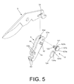
- FIG. 1 is an explosive view of an embodiment according to the present invention
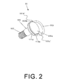
- FIG. 2 is a perspective view of a quick release device of an embodiment according to the present invention.
- FIG. 3 is a cross sectional view of a quick release device of an embodiment according to the present invention.
- FIG. 4 is a cross sectional view of a quick release device of an embodiment according to the present invention.
- FIG. 5 is an explosive view of a second quick release device and a connection part of an embodiment according to the present invention.
- FIG. 6 is an embodiment in an open state according to the present invention.
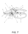
- FIG. 7 is an embodiment in a closed state according to the present invention.
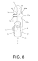
- FIG. 8 is a vertical cross sectional view of an embodiment according to the present invention.
- FIG. 9 is a perspective view of an embodiment according to the present invention.
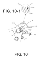
- FIG. 10 is a partial enlarged view of a first quick release device of an embodiment according to the present invention.
- FIG. 10-1 is partial enlarged cross sectional view of the embodiment in FIG. 10 according to the present invention.
- a cutting tool of the present invention include an upper handle 1 , a lower handle 2 , a blade 3 , a first pivot (shaft) 8 , a second pivot 9 , a first quick release device 11 , a second quick release device 12 , and a connection part 5 connecting the blade 3 and the lower handle 2 .
- the upper handle 1 consists of a holding part 1 b , a jaw part 1 a , a first pivot part 1 c , a first mounting hole 1 d and a receiving part 1 e .
- the holding part 1 b is wrapped by an elastic pad 4 .
- the jaw part 1 a extends from a front end to a rear end to form a hollow space 1 c ′ having two walls.
- the hollow space 1 c ′ is mounted with the first pivot part 1 c and the first mounting hole 1 d therein.
- the first pivot part 1 c penetrating the hollow space 1 c ′ transversely is aligned with a second pivot part 21 of the lower handle 2 , allowing the first pivot 8 to pass through and form a first pivot point A between the upper handle 1 and the lower handle 2 .
- a slot 1 a ′ is disposed on a front end of the jaw part 1 a and is used for receiving a pad 1 g .
- the pad 1 g is an elastic body used as a buffering structure for a cutting surface 31 of the blade 3 .
- the first mounting hole 1 d is arranged at the upper rear side of the first pivot part 1 c and is penetrating through the hollow space 1 c ′ transversely.
- a concave part 11 b and a limiting part 11 a are disposed on an outer surface of one side of the first mounting hole 1 d.
- the a lower handle 2 is composed of an assembly part 2 a , a handle part 24 , a second pivot part 21 , a third pivot part 22 and a receiving slot 23 .
- the assembly part 2 a is disposed on a front end of the lower handle 2 and the second pivot part 21 is arranged at the assembly part 2 a .
- the second pivot part 21 is aligned with the first pivot part 1 c of the upper handle 1 .
- the first pivot 8 passing through the first pivot part 1 c and the second pivot part 21 is defined as the first pivot point A.
- a third pivot part 22 is located between the assembly part 2 a and the handle part 24 and is aligned with a second axial hole 51 b of the connection part 5 .
- a second pivot 9 passing through the third pivot part 22 and the second axial hole 51 b is defined as a second pivot point B.
- the handle part 24 is arranged at a rear side of the lower handle 2 and having an upper receiving part 24 a and a lower receiving part 24 b integrated with each other.
- the receiving slot 23 is mounted on the upper receiving part 24 a and used for mounting a set of locking device 10 .
- the locking device 10 includes a first pushing block 10 a and a second pushing block 10 b .
- a rib part 101 is projecting from one end surface of the first pushing block 10 a while one end surface of the second pushing block 10 b is arranged with a mounting projection 102 .
- the rib part 101 of the first pushing block 10 a is just sleeved into a receiving nozzle 103 of the mounting projection 102 .
- the rib part 101 and the receiving nozzle 103 are locked with each other in the receiving slot 23 .
- the locking device 10 has anterior/posterior movement in the receiving slot 23 and the position is defined as a displacement D.
- the locking device 10 is used as a safety guard for preventing the blade 3 from moving.
- the blade 3 consists of the cutting surface 31 , an insertion hole 32 , a circular part 33 , a hook part 34 and a push part 35 .
- the cutting surface 31 is used for cutting and the insertion hole 32 is disposed on a middle part of the blade.
- a shaft component 111 of the first quick release device 11 pass through the first mounting hole 1 d of the upper handle 1 and then the insertion hole 21 so as to pivot the blade 3 on the upper handle 1 and the position is defined as the third pivot point C.
- the circular part 33 is a hollow window formed by a plurality of connected circles, arranged at the rear part of the blade 3 and used for displacement of a shaft component 121 of the second quick release device 12 pivoted on the connection part 5 .
- the hook part 34 is set on a rear end of the blade 3 .
- the hook part 34 is locked and fixed by the locking device 10 .
- a safety switch used for preventing opening of the blade 3 is formed.
- the present invention features on that a component that connects the blade 3 and the connection part 5 pivotally is a quick release device.
- a quick release device there are two quick release devices, a first quick release device 11 and a second quick release device 12 .
- the first quick release device 11 includes a shaft component 111 and a handle 113 .
- a perspective view of the first quick release device 11 is revealed.
- One end of the shaft component 111 is disposed with a threaded part 112 while the other end thereof is an enlarged part 111 a .
- a circular slot 111 d is arranged around the circumference of the enlarged part 111 a and a pair of symmetrical holes 111 b , 111 c is arranged radially at the enlarged part 111 a . Moreover, a recess 111 b ′, 111 c ′ is arranged at an outer end of the holes 111 b , 111 c respectively.
- the handle 113 is formed by bending of a long rod. Two symmetrical assembly parts 113 a , 113 b are disposed on two curved rear ends of the handle 113 respectively.
- the assembly parts 113 a , 113 b are mounted in an inner diameter of the holes 111 b , 111 c of the enlarged part 111 a so that the handle 113 swings around the enlarged part 111 a .
- the movement of the handle 113 is shown in FIG. 3 , FIG. 4 , FIG. 8 and FIG. 9 .
- the shaft component 111 of the first quick release device 11 is mounted into the first mounting hole 1 d and the handle 113 is sticking up in the enlarged part 111 a .
- the assembly parts 113 a , 113 b are extended due to the elasticity.
- the assembly parts 113 a , 113 b are retracted after entering the recesses 111 b ′, 111 c ′.
- the handle 113 is temporarily in a sticking state.
- the threaded part 112 of the shaft component 111 is engaged with threads preset inside the first mounting hole 1 d until the enlarged part 111 a is against an outer surface of the first mounting hole 1 d .
- the step of assembling the blade 3 on the upper handle 1 is completed.
- the handle 113 is pulled upward from the concave part 11 b and sticking up again.
- users rotate the handle in opposite direction and further drive the shaft component 111 to rotate.
- the threaded part 112 of the shaft component 111 is released from the threads preset inside the first mounting hole 1 d .
- the first quick release device 1 is completely removed from the first mounting hole 1 d and the blade 3 is released from the upper handle 1 .
- the second quick release device 12 is similar to that of the first quick release device 11 .
- the second quick release device 12 is passed through a first axial hole 51 a of the connection part 5 and connected to the circular part 33 of the blade 3 .
- the second quick release device 12 is for driving, used as an insertion pin that is inserted through the circular part 33 of the blade 3 .
- the connection part 5 is an integrated part formed by bending a plate and having a first surface 5 a and a second surface 5 b arranged symmetrically.
- One end of the first surface 5 a and the second surface 5 b is disposed with the first axial hole 51 a respectively while the other end of the first surface 5 a and the second surface 5 b is arranged with a second axial hole 51 b respectively.
- a mounting 53 is formed integratedly on the rear end of the connection part 5 while a locking part 52 is set on the first surface 5 a .
- An inner threads 51 a ′ is formed on an inner surface of one axial hole 51 a .
- a handle 124 of the second quick release device 12 is mounted into holes 123 b , 123 c of an enlarged part 123 a .
- the shaft component 121 is inserted through the first axial hole 51 a and connected to the circular part 33 of the blade 3 .
- Rotate the handle 124 and a threaded part 122 of the second quick release device 12 is engaged with the inner threads 51 a ′ of the axial hole 51 a . Stop rotation until a bottom surface of the enlarged part 123 a is against the first surface 5 a of the connection part 5 .
- the assembly of the blade 3 to the connection part 5 is completed.
- the inner surface of the first axial hole 51 a can also be without the inner threads 51 a ′while the second quick release device 12 is without the threaded part 122 correspondingly.
- the second quick release device 12 can still have the same functions of positioning and pivoting.
- the receiving part 1 e is a recess with a receiving space and having a first set of projecting ribs 11 e and a second set of projecting ribs 11 f so as to load a cleaner 6 .
- the cleaner 6 is a block made from wool felt or other materials for cleaning and is attached under an assembly block 61 .
- the assembly block 61 is disposed with two slots 61 a , 61 b that are corresponding to and aligned with the second set of ribs 11 f .
- the assembly block 61 is sliding and receiving in the receiving part 1 e .
- the first set of projecting ribs 11 e is for holding the cleaner 6 while the second set of projecting ribs 11 f is for positioning the assembly block 61 .
- the cleaner 6 is put inside the receiving part 1 e and users can use the cleaner 6 to clean the blade 3 periodically.
- the assembly part 2 a is located between the second pivot part 21 and the third pivot part 22 of the lower handle 2 .
- the assembly part 2 a can be used to receive an elastic member 13 that is a long spiral spring.
- One end of the elastic member 13 is against the assembly part 2 a and connected to the mounting part 53 of the connection part 5 while the other end thereof is against the push part 35 of the blade 3 .
- the blade 3 received in the jaw part 1 a can be pushed upward by the elastic member 13 so as to make the blade 3 in an open state.
- the lower handle 2 is defined as a rod held by the user's fingers and being pushed toward the upper handle 1 while the upper handle 1 is defined as a rod held by the user's palm and being squeezed toward the lower handle 2 .
- the two ends of the connection part 5 are respectively pivotally connected to the lower handle 2 and the circular part 33 of the blade 3 .
- the first axial hole 51 a is pivotally connected to the circular part 33 of the blade 3 by the shaft component 121 of the second quick release device 12 is defined as a point of application D.
- the blade 3 is pressed downward by the front end of the holding part 1 b . Then the connection part 5 is acted relatively like a link. Thus the shaft component 121 (the point of application D) of the second quick release device 12 in the circular part 33 is switched and moved forward. The blade 3 is further moved toward and close to the jaw part 1 a for providing the function of cutting.
- the way of lifting the blade 3 is as followings. The blade 3 is expanded by the elastic member 13 between the upper handle 1 and the lower handle 2 . At the same time, a switching is performed by the connection part 5 .
- the shaft component 121 (the point of application D) of the second quick release device 12 in the circular part 33 is moved backward to expand the upper handle 1 and allow the jaw part 1 a and the blade 3 being separated from each other. This is the open state of the cutting tool.
- the operation processes mentioned above are similar to prior art.
- a safe lock is revealed. While not in use, the safety lock is used to keep the blade 3 and the jaw part 1 a closed.
- the locking device 10 is slidable in the receiving slot 23 .
- the mounting projection 102 of the locking device 10 slides toward the hook part 34 of the blade 3 , the mounting projection 102 blocks the hook part 34 of the blade 3 to prevent the blade 3 from rotating.
- the blade 3 , the upper handle 1 , and the lower handle 2 are in a closed state.
- the present invention features on that the assembly part 2 a of the lower handle 2 is sleeved into the hollow space 1 c ′ of the jaw part 1 a of the upper handle 1 .
- the assembly part 2 a is enclosed between two walls of the hollow space 1 c ′ of the jaw part 1 a of the upper handle 1 .
- the advantage of such design is in that the first pivot point A of the upper handle 1 and the lower handle 2 is hidden because that the assembly part 2 a of the lower handle 2 is enclosed in the two walls of the hollow space 1 c ′ of the jaw part 1 a of the upper handle 1 . Thus no small debris will enter a gap between the first pivot part 1 c and the second pivot part 21 . Thus the first pivot point A is always rotated smoothly.
- the quick release device can be used as a pivot of each pivot point of the cutting tool in the present invention for quick and convenient replacement of the blade 3 .
- the blade 3 is pivotally connected to the first pivot part 1 c of the upper handle 1 and the first axial hole 1 a of the connection part 5 by the first quick release device 1 and the second quick release device 2 respectively.
- the handle 113 / 124 of the first/second quick release device 11 / 12 is pulled away from the limiting part 11 a /the locking part 52 and then the handle 113 / 124 is rotated clockwise/counterclockwise.
- first/second quick release device 11 / 12 is completely removed from the upper handle 1 /the connection part and the blade 3 is released at the same time for assembling the new blade 3 later. Therefore the pivotal connection is achieved by the quick release device of the present invention, without using any other tools.
- a further advantage of the present invention is that the handle 113 / 124 is locked on the limiting part 11 a /the locking part 52 a after the first/second quick release device 11 / 12 being pivoted. That means the first quick release device and the second quick release device 11 , 12 are stopped, unable to be rotated any more. Even the cutting device has been used for a plurality of times after a long run, the position where the first/second quick release device 11 / 12 being pivotally connected will not get loose. The connections between components of the cutting tool are firmly, not easily getting loose or deformed. Once a large counterforce is posed on the cutting tool, the blade 33 is still fastened firmly on the handles.
- the locking part 52 has the same positioning function as the limiting part 11 a and a projection 11 a ′ shown in FIG. 10 . That means the locking part 52 is used to limit and keep the handle 113 / 124 stable.
- the limiting part 11 a is formed by two symmetrical slots while the projection 11 a ′ is between the two symmetrical slots.
- the width of the projection 11 a ′ is a bit larger than the width of the handle 113 .
- the width of the locking part 52 is a bit larger than the width of the handle 124 (not shown in figure).
- a concave part is disposed on an inner bottom end of the projection 11 a ′ and of the locking part 52 . Due to the elasticity, the handle 113 / 124 enters the circular slot 111 d after being expanded by the enlarged part 111 a . Thus the handle 113 and the handle 124 are respectively mounted into the projection 11 a ′ and the locking part 52 . Refer to FIG. 10 and FIG. 10-1 , the circular slot 111 d is extended to a rear end b′ of the projection 11 a ′.
Landscapes
- Life Sciences & Earth Sciences (AREA)
- Forests & Forestry (AREA)
- Engineering & Computer Science (AREA)
- Mechanical Engineering (AREA)
- Biodiversity & Conservation Biology (AREA)
- Ecology (AREA)
- Environmental Sciences (AREA)
- Scissors And Nippers (AREA)
Abstract
Description
- 1. Field of the Invention
- The present invention relates to a cutting tool, especially to a cutting tool in which pivots and pivot parts are assembled and disassembled quickly.
- 2. Description of Related Art
- Refer to Taiwanese Pat No. M312405, a latch for handle of pruning shear is revealed. The latch for handles of pruning shears includes a first handle, a second handle, a blade, a connecting arm and a locking member. A cutting board is disposed on an end of the first handle while the second handle is pivotally connected to the first handle. The blade is pivoted and fixed on the first handle and is corresponding to the cutting board. A locking projecting block is arranged at a rear end of the blade. The connecting arm is pivoted between the second handle and the rear end of the blade. The locking member is formed by a pivot part extended from an inner surface of a pull grip with a locking slot arranged at a front side thereof. The pivot part is disposed with at least one elastic piece. The pivot part is mounted and fixed in a slot on an inner side surface of the second handle so that the elastic piece is against an inner wall of the slot.
- The above shear is a kind of lever suitable for cutting hard materials such as metal sheets, branches, etc. In order to increase the strength of the handle, the shears available now include handles made from metal such as aluminum alloy with an improved hardness and not easy to get damaged. After being used for a long period of time, the blade on the front end of the shears is usually damaged first and the whole shear is replaced by a new one. This is a kind of waste, not environmental friendly. Thus some manufacturers have designed the shears/scissors with replaceable blades. However, additional tools are required to replace the blade and components used for pivoting the blade have different sizes. It's time consuming and inconvenient for users to find out suitable tools and remove the blade.
- Thus there is room for improvement and a need to provide a pivoting component easily assembled and disassembled without any additional tools. The pivoting component is a quick release device with multiple functions such as quick disassembling and positioning
- Therefore it is a primary object of the present invention to provide a cutting tool that includes a quick release device disposed on a connection part and moved in a circular part on one end of a blade when an upper handle is changed from an open state to a closed state. The cutting tool of the present invention includes an upper handle, a lower handle, a blade, a first pivot, a second pivot, at least one quick release device and a connection part connecting the blade and the lower handle. The quick release device allows users to achieve quick pivoting and connection without any tools. The quick release device is used to not only connect the blade to the upper handle pivotally but also connect the connection part and the blade. The connection part is connected to a circular part of the blade, used as a driving device. One end of the connection part is pivotally connected to the lower handle to form a pivot point. The cutting tool features on that the quick release device on the connection part is moved in the circular part on one end of the blade so as to cut when the upper handle is changed from an open state to a closed state.
- In the present invention, the quick release device includes a first quick release device and a second quick release device. Each quick release device consists of a shaft component and a handle. A threaded part is disposed on one end of the shaft component while an enlarged part is arranged at the other end of the shaft component. A circular slot is arranged around the circumference of the enlarged part and a pair of holes is radially mounted on the enlarged part. The handle is formed by bending of a rod and two symmetrical assembly parts are disposed on two curved rear ends of the handle respectively. The assembly parts are mounted in an inner diameter of the holes of the enlarged part so that the handle swings around the enlarged part.
- The upper handle is composed of a holding part, a jaw part, a first pivot part, a first mounting hole and a receiving part. The holding part is wrapped by an elastic pad and the jaw part is used to receive pressure during the cutting of the blade.
- The jaw part extends from a front end to a rear end of the upper handle to form a hollow space with two walls. The hollow space is arranged with the first pivot part for connecting the upper handle and the lower handle. The first pivot passes through the first pivot part, used as a pivot point for opening and closing the upper handle and the lower handle. The first mounting hole is mounted above the first pivot part. A concave part and a limiting part are disposed on an outer surface of the first mounting hole.
- The receiving part is a recess with a receiving space and having a first set of projecting ribs and a second set of projecting ribs. A cleaner is received in the receiving part.
- The lower handle includes a handle part, a second pivot part, a third pivot part and a receiving slot. The handle part is arranged with an upper receiving part and a lower receiving part. The second pivot part is disposed on a front end of the lower handle and is used for being connected to the first pivot part of the upper handle. The third pivot part is arranged behind the second pivot hole and is aligned with an axial hole of the connection part to be passed through by a second pivot. The receiving slot is mounted on the upper receiving part and used for mounting a set of locking device. The locking device includes a first pushing block and a second pushing block. A rib part is projecting from one end surface of the first pushing block while one end surface of the second pushing block is arranged with a mounting projection. The rib part of the first pushing block is sleeved into the mounting projection of the second pushing block.
- The blade consists of a cutting surface, an insertion hole, a circular part, and a hook part. The cutting surface is used for cutting. The insertion hole is mounted on a middle part of the blade and is pivotally connected to the first mounting hole of the upper handle. The circular part is a hollow window formed by a plurality of connected circles, arranged at the rear part of the blade and used for restrict the displacement of a shaft component of the second quick release device. The hook part is disposed on a rear end of the blade. When the upper handle and the lower handle are in a closed state, the hook part is locked by the locking device for preventing the blade from opening.
- The structure and the technical means adopted by the present invention to achieve the above and other objects can be best understood by referring to the following detailed description of the preferred embodiments and the accompanying drawings, wherein:
-
FIG. 1 is an explosive view of an embodiment according to the present invention; -
FIG. 2 is a perspective view of a quick release device of an embodiment according to the present invention; -
FIG. 3 is a cross sectional view of a quick release device of an embodiment according to the present invention; -
FIG. 4 is a cross sectional view of a quick release device of an embodiment according to the present invention; -
FIG. 5 is an explosive view of a second quick release device and a connection part of an embodiment according to the present invention; -
FIG. 6 is an embodiment in an open state according to the present invention; -
FIG. 7 is an embodiment in a closed state according to the present invention; -
FIG. 8 is a vertical cross sectional view of an embodiment according to the present invention; -
FIG. 9 is a perspective view of an embodiment according to the present invention; -
FIG. 10 is a partial enlarged view of a first quick release device of an embodiment according to the present invention; -
FIG. 10-1 is partial enlarged cross sectional view of the embodiment inFIG. 10 according to the present invention. - Please refer to following embodiments for details, features and effects of the present invention.
- Refer to
FIG. 1 , an explosive view of an embodiment showing connection of respective components is revealed. A cutting tool of the present invention include anupper handle 1, alower handle 2, ablade 3, a first pivot (shaft) 8, asecond pivot 9, a firstquick release device 11, a secondquick release device 12, and aconnection part 5 connecting theblade 3 and thelower handle 2. - The
upper handle 1 consists of a holdingpart 1 b, ajaw part 1 a, afirst pivot part 1 c, a first mountinghole 1 d and a receivingpart 1 e. The holdingpart 1 b is wrapped by anelastic pad 4. Thejaw part 1 a extends from a front end to a rear end to form ahollow space 1 c′ having two walls. Thehollow space 1 c′ is mounted with thefirst pivot part 1 c and the first mountinghole 1 d therein. Thefirst pivot part 1 c penetrating thehollow space 1 c′ transversely is aligned with asecond pivot part 21 of thelower handle 2, allowing thefirst pivot 8 to pass through and form a first pivot point A between theupper handle 1 and thelower handle 2. Aslot 1 a′ is disposed on a front end of thejaw part 1 a and is used for receiving apad 1 g. Thepad 1 g is an elastic body used as a buffering structure for a cuttingsurface 31 of theblade 3. Thefirst mounting hole 1 d is arranged at the upper rear side of thefirst pivot part 1 c and is penetrating through thehollow space 1 c′ transversely. Aconcave part 11 b and a limitingpart 11 a are disposed on an outer surface of one side of the first mountinghole 1 d. - The a
lower handle 2 is composed of anassembly part 2 a, ahandle part 24, asecond pivot part 21, athird pivot part 22 and a receivingslot 23. Theassembly part 2 a is disposed on a front end of thelower handle 2 and thesecond pivot part 21 is arranged at theassembly part 2 a. Thesecond pivot part 21 is aligned with thefirst pivot part 1 c of theupper handle 1. Then thefirst pivot 8 passing through thefirst pivot part 1 c and thesecond pivot part 21 is defined as the first pivot point A. Athird pivot part 22 is located between theassembly part 2 a and thehandle part 24 and is aligned with a secondaxial hole 51 b of theconnection part 5. Then asecond pivot 9 passing through thethird pivot part 22 and the secondaxial hole 51 b is defined as a second pivot point B. Thehandle part 24 is arranged at a rear side of thelower handle 2 and having an upper receivingpart 24 a and a lower receivingpart 24 b integrated with each other. The receivingslot 23 is mounted on the upper receivingpart 24 a and used for mounting a set of lockingdevice 10. The lockingdevice 10 includes a first pushingblock 10 a and a second pushingblock 10 b. Arib part 101 is projecting from one end surface of the first pushingblock 10 a while one end surface of the second pushingblock 10 b is arranged with a mountingprojection 102. Therib part 101 of the first pushingblock 10 a is just sleeved into a receivingnozzle 103 of the mountingprojection 102. After therib part 101 of the first pushingblock 10 a being aligned with the receivingnozzle 103 of the second pushingblock 10 b, therib part 101 and the receivingnozzle 103 are locked with each other in the receivingslot 23. Thus thelocking device 10 has anterior/posterior movement in the receivingslot 23 and the position is defined as a displacement D. The lockingdevice 10 is used as a safety guard for preventing theblade 3 from moving. - The
blade 3 consists of the cuttingsurface 31, aninsertion hole 32, acircular part 33, ahook part 34 and apush part 35. The cuttingsurface 31 is used for cutting and theinsertion hole 32 is disposed on a middle part of the blade. Ashaft component 111 of the firstquick release device 11 pass through the first mountinghole 1 d of theupper handle 1 and then theinsertion hole 21 so as to pivot theblade 3 on theupper handle 1 and the position is defined as the third pivot point C. Thecircular part 33 is a hollow window formed by a plurality of connected circles, arranged at the rear part of theblade 3 and used for displacement of ashaft component 121 of the secondquick release device 12 pivoted on theconnection part 5. Thehook part 34 is set on a rear end of theblade 3. When theupper handle 1 and thelower handle 2 are in a closed state, thehook part 34 is locked and fixed by the lockingdevice 10. Thus a safety switch used for preventing opening of theblade 3 is formed. - Refer to
FIG. 2 ,FIG. 3 andFIG. 4 , the present invention features on that a component that connects theblade 3 and theconnection part 5 pivotally is a quick release device. In this embodiment, there are two quick release devices, a firstquick release device 11 and a secondquick release device 12. The firstquick release device 11 includes ashaft component 111 and ahandle 113. As shown inFIG. 2 , a perspective view of the firstquick release device 11 is revealed. One end of theshaft component 111 is disposed with a threadedpart 112 while the other end thereof is anenlarged part 111 a. Acircular slot 111 d is arranged around the circumference of theenlarged part 111 a and a pair ofsymmetrical holes enlarged part 111 a. Moreover, arecess 111 b′, 111 c′ is arranged at an outer end of theholes handle 113 is formed by bending of a long rod. Twosymmetrical assembly parts handle 113 respectively. Theassembly parts holes enlarged part 111 a so that thehandle 113 swings around theenlarged part 111 a. The movement of thehandle 113 is shown inFIG. 3 ,FIG. 4 ,FIG. 8 andFIG. 9 . - As shown in
FIG. 4 , theshaft component 111 of the firstquick release device 11 is mounted into the first mountinghole 1 d and thehandle 113 is sticking up in theenlarged part 111 a. Now theassembly parts assembly parts recesses 111 b′, 111 c′. Thus thehandle 113 is temporarily in a sticking state. Continue to rotate thehandle 113 and the threadedpart 112 of theshaft component 111 is engaged with threads preset inside the first mountinghole 1 d until theenlarged part 111 a is against an outer surface of the first mountinghole 1 d. Then pull thehandle 113 downward and theassembly parts enlarged part 111 a and then are turned back to be in an inner bottom end of theholes assembly parts enlarged part 111 a and located in thecircular slot 111 d. Thus one end of thehandle 113 is fixed on the limitingpart 11 a while the rear end of thehandle 113 is mounted in theconcave part 11 b, without being released from the limitingpart 11 a easily. - The step of assembling the
blade 3 on theupper handle 1 is completed. On the other hand, once users intend to remove theblade 3 from theupper handle 1, thehandle 113 is pulled upward from theconcave part 11 b and sticking up again. Then users rotate the handle in opposite direction and further drive theshaft component 111 to rotate. Thus the threadedpart 112 of theshaft component 111 is released from the threads preset inside the first mountinghole 1 d. Finally, the firstquick release device 1 is completely removed from the first mountinghole 1 d and theblade 3 is released from theupper handle 1. - Refer to
FIG. 5 , the secondquick release device 12 is similar to that of the firstquick release device 11. In the embodiment, the secondquick release device 12 is passed through a firstaxial hole 51 a of theconnection part 5 and connected to thecircular part 33 of theblade 3. The secondquick release device 12 is for driving, used as an insertion pin that is inserted through thecircular part 33 of theblade 3. Theconnection part 5 is an integrated part formed by bending a plate and having afirst surface 5 a and asecond surface 5 b arranged symmetrically. One end of thefirst surface 5 a and thesecond surface 5 b is disposed with the firstaxial hole 51 a respectively while the other end of thefirst surface 5 a and thesecond surface 5 b is arranged with a secondaxial hole 51 b respectively. A mounting 53 is formed integratedly on the rear end of theconnection part 5 while a lockingpart 52 is set on thefirst surface 5 a. Aninner threads 51 a′ is formed on an inner surface of oneaxial hole 51 a. Ahandle 124 of the secondquick release device 12 is mounted intoholes enlarged part 123 a. While assembling theblade 3 and theconnection part 5, theshaft component 121 is inserted through the firstaxial hole 51 a and connected to thecircular part 33 of theblade 3. Rotate thehandle 124 and a threadedpart 122 of the secondquick release device 12 is engaged with theinner threads 51 a′ of theaxial hole 51 a. Stop rotation until a bottom surface of theenlarged part 123 a is against thefirst surface 5 a of theconnection part 5. Next pull thehandle 124 downward on the lockingpart 52 so that the secondquick release device 12 is positioned. Thus the assembly of theblade 3 to theconnection part 5 is completed. Moreover, the inner surface of the firstaxial hole 51 a can also be without theinner threads 51 a′while the secondquick release device 12 is without the threadedpart 122 correspondingly. The secondquick release device 12 can still have the same functions of positioning and pivoting. - The receiving
part 1 e is a recess with a receiving space and having a first set of projectingribs 11 e and a second set of projectingribs 11 f so as to load acleaner 6. Thecleaner 6 is a block made from wool felt or other materials for cleaning and is attached under anassembly block 61. Theassembly block 61 is disposed with twoslots ribs 11 f. Thus theassembly block 61 is sliding and receiving in the receivingpart 1 e. The first set of projectingribs 11 e is for holding thecleaner 6 while the second set of projectingribs 11 f is for positioning theassembly block 61. Thereby thecleaner 6 is put inside the receivingpart 1 e and users can use thecleaner 6 to clean theblade 3 periodically. - The
assembly part 2 a is located between thesecond pivot part 21 and thethird pivot part 22 of thelower handle 2. Theassembly part 2 a can be used to receive anelastic member 13 that is a long spiral spring. One end of theelastic member 13 is against theassembly part 2 a and connected to the mountingpart 53 of theconnection part 5 while the other end thereof is against thepush part 35 of theblade 3. Thereby theblade 3 received in thejaw part 1 a can be pushed upward by theelastic member 13 so as to make theblade 3 in an open state. - Refer to
FIG. 6 andFIG. 7 , thelower handle 2 is defined as a rod held by the user's fingers and being pushed toward theupper handle 1 while theupper handle 1 is defined as a rod held by the user's palm and being squeezed toward thelower handle 2. The two ends of theconnection part 5 are respectively pivotally connected to thelower handle 2 and thecircular part 33 of theblade 3. Where the firstaxial hole 51 a is pivotally connected to thecircular part 33 of theblade 3 by theshaft component 121 of the secondquick release device 12 is defined as a point of application D. During the operation processes, the user's hand presses theupper handle 1 downward while thelower handle 2 is rotated around the first pivot point A and moved upward. Using the third pivot point C as a fulcrum, the
blade 3 is pressed downward by the front end of the holdingpart 1 b. Then theconnection part 5 is acted relatively like a link. Thus the shaft component 121 (the point of application D) of the secondquick release device 12 in thecircular part 33 is switched and moved forward. Theblade 3 is further moved toward and close to thejaw part 1 a for providing the function of cutting. On the other hand, the way of lifting theblade 3 is as followings. Theblade 3 is expanded by theelastic member 13 between theupper handle 1 and thelower handle 2. At the same time, a switching is performed by theconnection part 5. The shaft component 121 (the point of application D) of the secondquick release device 12 in thecircular part 33 is moved backward to expand theupper handle 1 and allow thejaw part 1 a and theblade 3 being separated from each other. This is the open state of the cutting tool. The operation processes mentioned above are similar to prior art. - Refer to
FIG. 7 , a safe lock is revealed. While not in use, the safety lock is used to keep theblade 3 and thejaw part 1 a closed. The lockingdevice 10 is slidable in the receivingslot 23. When the mountingprojection 102 of the locking device 10 s slides toward thehook part 34 of theblade 3, the mountingprojection 102 blocks thehook part 34 of theblade 3 to prevent theblade 3 from rotating. Thus theblade 3, theupper handle 1, and thelower handle 2 are in a closed state. - The present invention features on that the
assembly part 2 a of thelower handle 2 is sleeved into thehollow space 1 c′ of thejaw part 1 a of theupper handle 1. In other words, theassembly part 2 a is enclosed between two walls of thehollow space 1 c′ of thejaw part 1 a of theupper handle 1. - The advantage of such design is in that the first pivot point A of the
upper handle 1 and thelower handle 2 is hidden because that theassembly part 2 a of thelower handle 2 is enclosed in the two walls of thehollow space 1 c′ of thejaw part 1 a of theupper handle 1. Thus no small debris will enter a gap between thefirst pivot part 1 c and thesecond pivot part 21. Thus the first pivot point A is always rotated smoothly. - In the above embodiment, there are two
quick release devices blade 3. Theblade 3 is pivotally connected to thefirst pivot part 1 c of theupper handle 1 and the firstaxial hole 1 a of theconnection part 5 by the firstquick release device 1 and the secondquick release device 2 respectively. When users want to replace anew blade 3, thehandle 113/124 of the first/secondquick release device 11/12 is pulled away from the limitingpart 11 a/the lockingpart 52 and then thehandle 113/124 is rotated clockwise/counterclockwise. Thus the first/secondquick release device 11/12 is completely removed from theupper handle 1/the connection part and theblade 3 is released at the same time for assembling thenew blade 3 later. Therefore the pivotal connection is achieved by the quick release device of the present invention, without using any other tools. - A further advantage of the present invention is that the
handle 113/124 is locked on the limitingpart 11 a/the locking part 52 a after the first/secondquick release device 11/12 being pivoted. That means the first quick release device and the secondquick release device quick release device 11/12 being pivotally connected will not get loose. The connections between components of the cutting tool are firmly, not easily getting loose or deformed. Once a large counterforce is posed on the cutting tool, theblade 33 is still fastened firmly on the handles. Moreover, the lockingpart 52 has the same positioning function as the limitingpart 11 a and aprojection 11 a′ shown inFIG. 10 . That means the lockingpart 52 is used to limit and keep thehandle 113/124 stable. There are a plurality of ways to modify such structure for limiting and positioning. For example, the limitingpart 11 a is formed by two symmetrical slots while theprojection 11 a′ is between the two symmetrical slots. In another embodiment, the width of theprojection 11 a′ is a bit larger than the width of thehandle 113. The width of the lockingpart 52 is a bit larger than the width of the handle 124 (not shown in figure). A concave part is disposed on an inner bottom end of theprojection 11 a′ and of the lockingpart 52. Due to the elasticity, thehandle 113/124 enters thecircular slot 111 d after being expanded by theenlarged part 111 a. Thus thehandle 113 and thehandle 124 are respectively mounted into theprojection 11 a′ and the lockingpart 52. Refer toFIG. 10 andFIG. 10-1 , thecircular slot 111 d is extended to a rear end b′ of theprojection 11 a′. Thereby therear end 113′ of thehandle 113 is mounted and locked in thecircular slot 111 d on the rear end b′ of theprojection 11 a′ and thehandle 113 is further locked and positioned on the rear end b′ of theprojection 11 a′. - Additional advantages and modifications will readily occur to those skilled in the art. Therefore, the invention in its broader aspects is not limited to the specific details, and representative devices shown and described herein. Accordingly, various modifications may be made without departing from the spirit or scope of the general inventive concept as defined by the appended claims and their equivalents.
Claims (13)
Priority Applications (1)
| Application Number | Priority Date | Filing Date | Title |
|---|---|---|---|
| US13/962,019 US9511500B2 (en) | 2013-08-08 | 2013-08-08 | Cutting tool |
Applications Claiming Priority (1)
| Application Number | Priority Date | Filing Date | Title |
|---|---|---|---|
| US13/962,019 US9511500B2 (en) | 2013-08-08 | 2013-08-08 | Cutting tool |
Publications (2)
| Publication Number | Publication Date |
|---|---|
| US20150040407A1 true US20150040407A1 (en) | 2015-02-12 |
| US9511500B2 US9511500B2 (en) | 2016-12-06 |
Family
ID=52447334
Family Applications (1)
| Application Number | Title | Priority Date | Filing Date |
|---|---|---|---|
| US13/962,019 Expired - Fee Related US9511500B2 (en) | 2013-08-08 | 2013-08-08 | Cutting tool |
Country Status (1)
| Country | Link |
|---|---|
| US (1) | US9511500B2 (en) |
Cited By (12)
| Publication number | Priority date | Publication date | Assignee | Title |
|---|---|---|---|---|
| EP3156195A1 (en) * | 2015-10-16 | 2017-04-19 | Bor Sheng Industrial Co., Ltd. | Control device of cutting tool |
| EP3199308A1 (en) * | 2016-01-29 | 2017-08-02 | Bor Sheng Industrial Co., Ltd. | Control device of cutting tool |
| JP2017131175A (en) * | 2016-01-29 | 2017-08-03 | ボル シェン インダストリアル カンパニー,リミテッド | Control device of scissors |
| US20170215346A1 (en) * | 2016-01-29 | 2017-08-03 | Bor Sheng Industrial Co., Ltd. | Control Device of Cutting Tool |
| CN107018806A (en) * | 2016-01-29 | 2017-08-08 | 柏升工业股份有限公司 | Control device of shearing tool |
| USD945229S1 (en) * | 2019-09-24 | 2022-03-08 | Fiskars Finland Oy Ab | Hand pruner |
| USD948297S1 (en) * | 2020-01-22 | 2022-04-12 | Foshan Shunde Caiting Trade Co., Ltd. | Rotating bypass pruning shear with guard handle |
| US11592162B2 (en) * | 2019-12-23 | 2023-02-28 | Ideal Industries Lighting Llc | LED luminaire |
| USD986024S1 (en) * | 2021-08-13 | 2023-05-16 | Woodland Tools Inc. | Utility snips |
| USD992988S1 (en) * | 2021-05-05 | 2023-07-25 | Legreat International Corporation | Garden shears |
| USD992986S1 (en) * | 2021-05-05 | 2023-07-25 | Legreat International Corporation | Garden shears |
| US20250120550A1 (en) * | 2021-03-09 | 2025-04-17 | Zachary Brandt | Cutting Apparatuses |
Families Citing this family (2)
| Publication number | Priority date | Publication date | Assignee | Title |
|---|---|---|---|---|
| US12202155B2 (en) | 2020-09-10 | 2025-01-21 | Techtronic Cordless Gp | Blade change mechanism for power tool |
| AU2021104983A4 (en) * | 2020-09-10 | 2021-09-30 | Techtronic Cordless Gp | Blade replacement mechanism of electric instrument |
Citations (10)
| Publication number | Priority date | Publication date | Assignee | Title |
|---|---|---|---|---|
| US4189804A (en) * | 1978-03-24 | 1980-02-26 | Keeler Corporation | Back plate and bail assembly |
| US5527329A (en) * | 1993-12-08 | 1996-06-18 | Devon Industries, Inc. | Surgical scalpel |
| US5599351A (en) * | 1993-12-08 | 1997-02-04 | Habley Medical Technology Corporation | Scalpels having permanent blade retraction |
| US6153331A (en) * | 1999-05-14 | 2000-11-28 | Delphi Technologies, Inc. | Battery handle holddown |
| US7186067B2 (en) * | 2004-05-17 | 2007-03-06 | Irwin Industrial Tool Company | Fastener with attached pivotable handle |
| US20070256308A1 (en) * | 2006-05-05 | 2007-11-08 | Chorng-Jiang Lin | Pruners with replaceable part |
| US7328513B1 (en) * | 2006-01-31 | 2008-02-12 | Chung Cheng Yang | Cutter having changeable carrier |
| US20110061249A1 (en) * | 2009-09-13 | 2011-03-17 | Man For Ma | Cutting Implement with Interchangeable/Replaceable Blades |
| US20110283545A1 (en) * | 2010-05-23 | 2011-11-24 | Jiin Haur Industrial Co.,Ltd. | Garden shears |
| US8327548B2 (en) * | 2009-02-23 | 2012-12-11 | Ronan John S | Utility cutter with a non-tool blade changer |
Family Cites Families (2)
| Publication number | Priority date | Publication date | Assignee | Title |
|---|---|---|---|---|
| US317637A (en) * | 1885-05-12 | Peteha | ||
| US6000307A (en) * | 1998-02-05 | 1999-12-14 | Aamodt; Robert Wayne | Utility cutting tool and method |
-
2013
- 2013-08-08 US US13/962,019 patent/US9511500B2/en not_active Expired - Fee Related
Patent Citations (10)
| Publication number | Priority date | Publication date | Assignee | Title |
|---|---|---|---|---|
| US4189804A (en) * | 1978-03-24 | 1980-02-26 | Keeler Corporation | Back plate and bail assembly |
| US5527329A (en) * | 1993-12-08 | 1996-06-18 | Devon Industries, Inc. | Surgical scalpel |
| US5599351A (en) * | 1993-12-08 | 1997-02-04 | Habley Medical Technology Corporation | Scalpels having permanent blade retraction |
| US6153331A (en) * | 1999-05-14 | 2000-11-28 | Delphi Technologies, Inc. | Battery handle holddown |
| US7186067B2 (en) * | 2004-05-17 | 2007-03-06 | Irwin Industrial Tool Company | Fastener with attached pivotable handle |
| US7328513B1 (en) * | 2006-01-31 | 2008-02-12 | Chung Cheng Yang | Cutter having changeable carrier |
| US20070256308A1 (en) * | 2006-05-05 | 2007-11-08 | Chorng-Jiang Lin | Pruners with replaceable part |
| US8327548B2 (en) * | 2009-02-23 | 2012-12-11 | Ronan John S | Utility cutter with a non-tool blade changer |
| US20110061249A1 (en) * | 2009-09-13 | 2011-03-17 | Man For Ma | Cutting Implement with Interchangeable/Replaceable Blades |
| US20110283545A1 (en) * | 2010-05-23 | 2011-11-24 | Jiin Haur Industrial Co.,Ltd. | Garden shears |
Non-Patent Citations (1)
| Title |
|---|
| Definition of "Circular" accessed at http://www.merriam-webster.com/dictionary/circular on 21 December 2015. * |
Cited By (13)
| Publication number | Priority date | Publication date | Assignee | Title |
|---|---|---|---|---|
| EP3156195A1 (en) * | 2015-10-16 | 2017-04-19 | Bor Sheng Industrial Co., Ltd. | Control device of cutting tool |
| EP3199308A1 (en) * | 2016-01-29 | 2017-08-02 | Bor Sheng Industrial Co., Ltd. | Control device of cutting tool |
| JP2017131175A (en) * | 2016-01-29 | 2017-08-03 | ボル シェン インダストリアル カンパニー,リミテッド | Control device of scissors |
| US20170215346A1 (en) * | 2016-01-29 | 2017-08-03 | Bor Sheng Industrial Co., Ltd. | Control Device of Cutting Tool |
| CN107018806A (en) * | 2016-01-29 | 2017-08-08 | 柏升工业股份有限公司 | Control device of shearing tool |
| US10130042B2 (en) * | 2016-01-29 | 2018-11-20 | Bor Sheng Industrial Co., Ltd. | Control device of cutting tool |
| USD945229S1 (en) * | 2019-09-24 | 2022-03-08 | Fiskars Finland Oy Ab | Hand pruner |
| US11592162B2 (en) * | 2019-12-23 | 2023-02-28 | Ideal Industries Lighting Llc | LED luminaire |
| USD948297S1 (en) * | 2020-01-22 | 2022-04-12 | Foshan Shunde Caiting Trade Co., Ltd. | Rotating bypass pruning shear with guard handle |
| US20250120550A1 (en) * | 2021-03-09 | 2025-04-17 | Zachary Brandt | Cutting Apparatuses |
| USD992988S1 (en) * | 2021-05-05 | 2023-07-25 | Legreat International Corporation | Garden shears |
| USD992986S1 (en) * | 2021-05-05 | 2023-07-25 | Legreat International Corporation | Garden shears |
| USD986024S1 (en) * | 2021-08-13 | 2023-05-16 | Woodland Tools Inc. | Utility snips |
Also Published As
| Publication number | Publication date |
|---|---|
| US9511500B2 (en) | 2016-12-06 |
Similar Documents
| Publication | Publication Date | Title |
|---|---|---|
| US9511500B2 (en) | Cutting tool | |
| CN111051018B (en) | Double-blade locking mechanism | |
| US11458609B2 (en) | Multipurpose tool | |
| US10130042B2 (en) | Control device of cutting tool | |
| US9596810B2 (en) | Gardening scissor | |
| US8266804B2 (en) | Garden shears | |
| US8037787B2 (en) | Multi-function tool having retractable jaws | |
| TWM541937U (en) | Combinational structure of knife and sheath | |
| CA2720941C (en) | Tool having an integral carabiner | |
| EP1993789A2 (en) | Folding tool with lockback mechanism | |
| TWI633834B (en) | Gardening shears that increase structural strength | |
| US10730195B2 (en) | Pull-type cutters | |
| US20110185577A1 (en) | Hand-held cutter with an auxiliary handle for performing an initial cutting operation | |
| TWI776761B (en) | Cutter adapted to engage with a power tool | |
| KR101837730B1 (en) | Cutter for the stalk of a garlic | |
| WO2015109941A1 (en) | Holding device and electric tool comprising same | |
| US9446527B1 (en) | Pull-type cutters | |
| EP3199308B1 (en) | Cutting tool with control device | |
| TWM512485U (en) | Gardening shears | |
| TWI563910B (en) | Control device for shearing | |
| CN211881169U (en) | garden shears | |
| CN219679993U (en) | Nail clipper with push lock | |
| CN100423907C (en) | tool set | |
| TWM471352U (en) | Improved structure of clippers | |
| TWI593530B (en) | Utility knife structure |
Legal Events
| Date | Code | Title | Description |
|---|---|---|---|
| AS | Assignment |
Owner name: BOR SHENG INDUSTRIAL CO., LTD., TAIWAN Free format text: ASSIGNMENT OF ASSIGNORS INTEREST;ASSIGNOR:LIN, SHIH-CHANG;REEL/FRAME:030967/0502 Effective date: 20130730 |
|
| STCF | Information on status: patent grant |
Free format text: PATENTED CASE |
|
| FEPP | Fee payment procedure |
Free format text: MAINTENANCE FEE REMINDER MAILED (ORIGINAL EVENT CODE: REM.); ENTITY STATUS OF PATENT OWNER: SMALL ENTITY |
|
| LAPS | Lapse for failure to pay maintenance fees |
Free format text: PATENT EXPIRED FOR FAILURE TO PAY MAINTENANCE FEES (ORIGINAL EVENT CODE: EXP.); ENTITY STATUS OF PATENT OWNER: SMALL ENTITY |
|
| STCH | Information on status: patent discontinuation |
Free format text: PATENT EXPIRED DUE TO NONPAYMENT OF MAINTENANCE FEES UNDER 37 CFR 1.362 |
|
| FP | Lapsed due to failure to pay maintenance fee |
Effective date: 20201206 |