US2014792A - Excavating apparatus - Google Patents
Excavating apparatus Download PDFInfo
- Publication number
- US2014792A US2014792A US710223A US71022334A US2014792A US 2014792 A US2014792 A US 2014792A US 710223 A US710223 A US 710223A US 71022334 A US71022334 A US 71022334A US 2014792 A US2014792 A US 2014792A
- Authority
- US
- United States
- Prior art keywords
- bucket
- buckets
- wheel
- valve
- arc
- Prior art date
- Legal status (The legal status is an assumption and is not a legal conclusion. Google has not performed a legal analysis and makes no representation as to the accuracy of the status listed.)
- Expired - Lifetime
Links
Images


Classifications
-
- E—FIXED CONSTRUCTIONS
- E02—HYDRAULIC ENGINEERING; FOUNDATIONS; SOIL SHIFTING
- E02F—DREDGING; SOIL-SHIFTING
- E02F3/00—Dredgers; Soil-shifting machines
- E02F3/04—Dredgers; Soil-shifting machines mechanically-driven
- E02F3/18—Dredgers; Soil-shifting machines mechanically-driven with digging wheels turning round an axis, e.g. bucket-type wheels
- E02F3/22—Component parts
- E02F3/24—Digging wheels; Digging elements of wheels; Drives for wheels
- E02F3/245—Digging wheels; Digging elements of wheels; Drives for wheels with digging elements mounted movable relative to the wheel
Landscapes
- Engineering & Computer Science (AREA)
- Mechanical Engineering (AREA)
- Mining & Mineral Resources (AREA)
- Civil Engineering (AREA)
- General Engineering & Computer Science (AREA)
- Structural Engineering (AREA)
- Earth Drilling (AREA)
Description
e sheets-sheet '2 Filed Feb. 8, 1954 sem. 17, 1935.. R. s. WEIMER 2,014,792
EXCAVATING APPARATUS Filed Feb. 8, 1934 .6 Sheets--Sheety 3 sem; w, 135.
R. S. WEIMER EXGAVATING APPARATUS Filed Feb.
8, 1934 6 Sheets-Sheet 4 @@pt W, H935.. 4 R, s WEIMER ZMJQZ EXCAVATING APPARATUS Filed Feb. 8, 1934 e shets-sheet 5 re WWMMW Jaffa/WW R. S. WEIMEIR l WK, K3.
EXCAVATING APPARATUS Filed Feb. 8, 1954 6 Sheets-Shea?l 6 j?? Ute/e227" 2549/7202307 f/272W y W fa/"leafy f Patented Sept. 17, 1935 .er 'rre Arai* FFIQE 22 Claims.
This invention relates to improvements in excavating apparatus.
One object of the invention is to provide excavating apparatus comprising a rotary struczture or wheel provided with one or more excavating buckets, each oi which during a certain arc of rotation, is manually controllable, while during the remaining arc of rotation and during which the dumping oi the buckets takes l place, the buckets are controlled automatically.
Another object of the invention is to provide a rotary excavating structure having radially extendible buckets under manual control during an are of rotation within which the excavating or digging action takes place, and automatic control means for each bucket for eecting the dumping of the contents, as into a hopper, for example, and retracting the buckets after dumping to pass the hopper, whereby the Wheel can be operated continuously and the attention oi the operator is required only as to the buckets as they move in succession into excavating position.
A further object of the invention is to provide hydraulically or pressure-ud actuated mechanism for operating the buckets during the period of manual, as well as of automatic control.
The invention is broadly characterized by the provision of a rotary wheel or like structure which carries a plurality of excavating buckets each of which moves during each rotation of the wheel into an arc oi manual control wherein the operator can cause the bucket within such arc to be extended or retracted substantially radially of the wheel as may be necessary in taking on the desired load. The loaded buckets are carried in succession to a point where the dumping of the contents is automatically efiected, as into a hopper from which the material is conveyed away by suitable conveyors, after which dumping action the buckets again more into the arc oi manual control.
A further object is to provide an excavating 'i wheel the buckets of which are provided with pressure fluid actuated pistons for moving the buckets radially of the wheel, the fluid being controlled by valves which in turn are controlled automatically within a certain arc oi rotation of the wheel and are manually controllable within another are of rotation.
Another object oi the invention is to provide a rotary structure having pivotally mounted thrust members provided with buckets at the outer ends which are connected to the structure with link members which not only resist the operating stresses on the buckets and thrust members in a circumferential direction but cooperate with the thrust members to eiect a peripheral acceleration or deceleration of the respective buckets 5 as the same are moved outwardly or inwardly respectively by the thrust members.
Other objects relate to various features of construction and arrangement of parts which will be apparent from a consideration 'of the following 10 specification and accompanying drawings, where- Figure l is a broken side elevation of excavating apparatus embodying the present improvements. 15
Figure 2 is an enlarged broken side elevation of the rotary excavating mechanism.
Figure 3 is a broken sectional View taken approximately on line 3 3 of Figure 2.
Figure 4 is a detailed sectional view taken on 20 line Il fl of Figure 2.
Figure 5 is a section taken along line 5 5 of Figure 6.
Figure 6 is a section taken approximately on line 5 5 of Figure 5.
Figure 7 is an enlarged sectional View, with parts broken away, taken along line 1 1 of Figure 2.
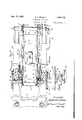
Figure 8 is a sectional view of one of the piston control valves taken on line 8 8 of Fig- 30 ure 6.
Figure 9 is a similar sectional view but showing the valve in another position.
Figure l0 is a sectional view of the valve taken on line id i i3 of Figure 9. 35 Figure ll is a development of the cam by means of which the piston control valves shown in Figures 8, 9 and l0 are operated.
Figure l2 is a broken elevation of a valve which controls the piston which effects the tilting of 40 a bucket.
Figure 13 is a sectional view taken on line lli-i3 of Figure 12.
Figure 14 is a sectional View through the valve taken on line M ll of Figure 12.
In the drawings an embodiment of the invention is shown which is designed for large capacity wo-rk such as in removing the over-burden in strip mining.
In Figure l of the drawings there is shown a 50 carriage i9 having mounted thereon a turntable il upon which is mounted a conveyor l2 which carries the soil removed by the excavator to a spoil pile, not shown. Also carried by the main turntable H is a second turntable I3 which oar- 55 ries a hopper I4 into which the excavator discharges the soil and from which it is discharged into the conveyor which may be an endless conveyor or a conveyor of the car type such as is shown in my Patent Number 1,956,738.
The turntables I I and I3 are provided with any suitable means for operating the same, such as is disclosed in my above application.
Also mounted on the turntable I3 is a boom indicated generally by the numeral I5. The boom supports the excavating wheel I6. The boom may be raised or lowered by any suitable means such as by means of a power operated cable I'I, also more specifically described in the above mentioned application.
Referring to Figure 3, it will be seen that the boom generally indicated by the numeral I5, has two similar sections I5a. These sections are spaced apart suillciently to accommodate the excavating wheel I6. The wheel in the form shown is constructed of structural steel and comprises a central hub I8 secured to opposite plates I9 tol which are secured the radial ribs or spokes 20. An outer annular plate or rim 2| is secured to the spokes 28, to which member 2I are secured annular members 22 which are provided with teeth 23.
Mounted on each of the boom sections I5a are motors 24, each of which is provided with a driving pinion 25 which drives the gears 26 carried by the shaft 2'I mounted on bearings 28 carried by the boom sections.
The shafts 2'I carry pinions 29 which in turn drive the gears 30 carried by the shafts 3I.
The shafts 3l are provided with driving pinions 32 which mesh with the teeth 23 of the annular members 22, for rotating the Wheel I6.
The hub member I8 of the wheel is mounted on the stationary shaft 33 carried by the ends of the boom members I5a.
The shaft 33 is shown in Figure 6 as being keyed at 34 to the boom members I5a, which at their ends are provided with housings |51)` for supporting the shaft, Also in said gure, bearings 35 are shown disposed between the hub I8 and the shaft 33, and additional bearings 36 between the ends of the hub and the adjacent ends of the housings I5b.
When the motors 24 operate they will through the mechanism above described, effect the rotation of the wheel in counter-clockwise direction, as viewed in Figures 1 and 2.
In Figure 4 a roller 3'I is shown mounted in bearings 38 carried by the boom members I5a which rollers bear against the upwardly turned flanges 22a of the members 22 to prevent side sway of the wheel, and thus hold the teeth 23 in engagement with the pinions 32. The position of the rollers in side elevation is shown also in Figure 2.
As shown in Figures 1 and 2, the wheel I6 is provided with a plurality of excavating buckets A, B, C and D. Each of the buckets is pivotally mounted at 39 to a thrust member 48 which can be moved substantially radially inwardly or outwardly by mechanism hereinafter described during the rotation of the wheel.
Referring to Figure 2 it will be seen that bucket A has just entered excavating position, and that bucket B is approaching the limit of excavating position. Bucket C has been retracted inwardly toward the periphery of the wheel and has been rotated upon its pivot 39 in a clockwise direction so as to retain the contents thereof against spilling. Bucket D is shown in extended position and tilted counter-clockwise from the position shown at C so as to discharge its contents into the hopper shown fragmentarily at I4.
Immediately after the discharge of the contents into the hopper, the bucket D will be re tracted so as to pass the hopper and move in such retracted or semi-retracted position into the excavating arc. The arc of rotation represented by the movement of any bucket from the position of bucket A to bucket B is the arc during which excavation takes place. As each bucket passes into said arc, it comes within the control of an operator located in the station 4I, which may be carried by the turntable I3 or positioned at any other convenient place on the superstructure of the carriage I0.
Each bucket in passing from the position of bucket B around to the position of bucket A is automatically controlled, whereby the operator need pay no attention to the dumping of thc buckets, but can give his entire attention to eachl bucket as it passes into and through the arc of excavation.
In the embodiment of the invention herein shown, the movement of the buckets radially while under automatic or manual control is effected by pressure fluid. In Figure 2 there is shown a motor 42 which operates a fluid compressor 43 which members are carried by a transverse shelf 44 extending between a pair of opposite ribs or spokes 20, as shown in Figure 3. The compressor 43 delivers fluid through pipe 45 to a high pressure tank 46 also attached by any suitable means to the wheel structure. The fluid passes from the high pressure tank 45 through a conduit 41 to branch conduits 48 and 49, each of which delivers fluid under pressure to a cylinder having therein a double acting piston which operates the thrust member inwardly or outwardly under either automatic or manual control.
Exhaust fluid from the piston, which will be described later, returns through branch conduits 50 and 5I which connect with the return pipe 52, which delivers the fluid to a low pressure tank 53. From the low pressure tank the compressor 43 draws the fluid through the pipe 54 and compresses the same and discharges it through the pipe into the high pressure tank 46.
The fluid compressing, delivery and return system just described, serves the operating pistons of the buckets D and A. Diametrically opposite of the wheel is another fluid compressing, delivery and return system, which is identical with that just described, but which serves operating pistons of the buckets B and C. The corresponding elements of the latter system are given corresponding primed designating numerals,
Referring to Figure 6 it will be seen that the hub I8 of the wheel is provided with radial flanges I8a which are provided with bearings I8b in which are journaled the arms of the cylinder 56. As there are four buckets shown, there will be, of course, four similar cylinders, the description of one of which will suffice.
The outer end of each cylinder 56 is connected to a guiding tube 51 which at its outer end, as shown in Figures 2 and "I is supported by opposite guides 58 extending between two adjacent spokes 2B of the wheel. The guides 58 permit the cylinder construction to pivot within the bearings I8b within a central plane of the wheel, but prevent lateral movement of the cylinder structure.
animee Within the cylinder 56 is a piston 59fhaving a tubular extension 5i) which projects into the guiding sleeve 5l, andis there secured as by boltsi to the thrust member All.
The piston head'59 is centrally apertured-and slidesA on a tube` 62 which at its outer end is supportedby a piston closure member 63, and adjacent its inner end by a spider-like vmember 615 having an outwardly turned ange 65 disposed between the end of the piston 55 and avalve casing-56. The outer end of the tuber62 vis provided with openings 6l which permit pressure uid to flow from the tube into the chamber v68 and thus act against the inside of the piston headf59, orto permit uid Within the chamber 68 to ow into the tube '52 when the pistonhead is moved toward the closure member as viewed in Figure 6.
On the inner end of the tube'62 is movably mounted a `Valve 55 of disc-like form, and having formed in the margins thereof two groups of ports 11E! and lita, and?! and lla, respectively, (see Figures 8 and 9) The valve 69, as shown in Figure 6, is provided `with atransverse member 'l2 which does noty close lthe end ofthe tube 52 and from which member l2 extends an axial shaft 73. The shaft extends through the cover 68a of the valve casingt, and is provided With a packing gland 14 to prevent `leakage of huid round the shaft.
The shaft is provided with a crank arm 'l5 to `which is pivoted an operating rod i6 which is supported by a bracket "i8 secured to the hub i8, and
carries a roller 'i9 at its outer end. The roller is positioned in acam trackway of a cam 8| which is secured to the stationary portion |51) of '1l into registration with the fluid inlet port 82 and likewise to move either exhaust port ll or 'Ha into registration with the uid exhaust port 83.
As shown in Figure 6, pressure fluid from pipe 43 flows into the pipe 84 to the intake port 82, said pipe being positioned coaxially with reference tothe pivo-ted arms 55 rofthe piston structure. Thus in the position shown in Figure 6, pressure iiuid can pass through the inlet port 82 and will be directed by the valve port "HJ into the casing 66, and into the cylinder 55 to force the piston'59 outwardly or vertically, as shown in Figure 6. The movement of the piston outwardly forces the thrust member lli outwardly to which the respective bucket is secured.
"During the outward movement of the piston 55, as just described, any exhaust fluid within the chamber 68 will be forced through the openings `6l of the tube 62, and pass through the tube and thence through the outlet port 83 into the pipe 85 which is also coaxially mounted with respect to the pivoted ends of the arm 55. The uid passing through the pipe 85 enters the branch exhaust pipe 50, from which it flows to the pipe 52, (see Figure 2) back into the low pressure reservoir 53.
If the valve operating rod 'l5 is moved to the right, as viewed in Figure 6, by the cam, the valve 69 will occupy the position shown in Figure 16. This pressure fluid will enter the pipe it through the valve port 15a, and will enter the inner end of the tube 62, and Will flow through the openings l'iiintothe chamber .68'and exert v.presmovement of the respective bucket inwardly to- 5 ward the periphery'of the wheel. Whenthe pis- -ton is moving toward the position shown in Figure 6, the previous charge of fluid will be exhausted through the valve port 'Het (see Figure 10) into thepipe 85, and thence into branch pipe 10l 55 which, as before stated, communicates with the mainreturn pipe52, which conveys'the exhaust uid to the low pressure reservoir.53.
As shown in Figures l and 2, apair of tension arms 86 is pivotally attached at 81 to each bucket 175` and also at 88 to a portion of the wheel I6. These tension arms carry the stresses exerted circumferentially on the bucket during the cycle of operation. 'I'hese arms B6 will cause a slight pivotal movement of the bucket and cylinder 20 structures about the journaled ends of the arms 55 when the pistons move inwardly or outwardly.
Such .pivotal movement will, of course, tend to swing the valve shaft 13 slightly, but such move- Vment with reference to the rod 'i5 is accommo- 25` dated bythe provision of a slot 15a inthe arms "l5 through which the pivot pin 'l5b'passes, (seeFg- -ures .8 and 9).
The cam `8| which operates the `rods 16 is .shown in section in Figure 6. In this gure, 30
two of the rods i6 are also shown but it Will be ,understood that similar rods are `provided for the other two cylinder mechanisms which are not shown in said figure. The relative positions ofthe rods 16 are, however, shown in -Fig- 35 ure 5.
A development of the cam y8l is `'shown in Figure ll. It will be seen that the track or channel 8U of the cam has portions thereof offset from the central line of the track indicated 40 bythe broken line Bia, As the respective'rollers i9 move along vthe channel 80 during the `rotation of the wheel I5, the vchannel will `effect 4the cam track, no outward or inward movement of the respective piston will take place.
The cam is provided With a laterally adjustablesec- 55 tion comprising members B5, and 9|. The central section 95 is carried by a slide 92 which is carried by the supporting guide 93 -(see Figure 5) which is attached to the hub i8 of the Wheel i5. 60 Secured to the slide 92 yis an operating rod94 which extends laterally of the wheel as shown in Figure 6, and at its outer end is connected to a lever "95 Ywhich is pivoted at'96'to a bracket 497 secured to an end of the stationary shaft 33. The 55 bracketQ'ihas anoffset arm 58 on Whichis pivoted another lever ASvhaving Yan opening in'one end through which the rLipper end of the lever -95 extends. The oppositeend ofthe'lever 99 is A,pivoted to an operating rod im] (see Figure 2) 'which 70 extends to the operator station 4I, and is there the right as viewed in Figure 2, the rod will be retracted. This movement will swing the lever 99 in a direction to operate the lever 95 in counter-clockwise direction, and move the cam shift rod 94 to the right as viewed in Figure 6. The movement of the rod 94 effects the shifting movement of the adjustable cam section. As shown in Figure ll the adjustable cam section can be moved to the full line position, or to the dotted line position. It may, of course, be moved to any intermediate position.
The rollers 19 carried by the arms 'l in passing along the channel Sil or" the cam, effect the shifting of the respective valves 55 as above described. Referring to Figure ll, the rollers l@ move from left to right. As a roller moves into the adjustable section of the cam, its path of travel can be controlled by sliding the section 92 within the member 93. This lateral movement of the roller eiTects the adjustment of the respective valve 16, so that the piston controlled by such valve will be moved outwardly or inwardly, or held in a stationary relation with reference to the wheel.
Thus, if a roller travels along the adjustable section shown in full lines in Figure l1, the rod 'I6 carried by such roller will be shifted from the position shown in Figure to the position shown in Figure 6, and pressure fluid will enter the cylinder to force the piston outwardly, and thus move the respective bucket outwardly. Should the adjustable section be moved in alignment with the center line 8l a, the valve will be retained in intermediate position with the result that the bucket will be moved neither outwardly nor inwardly. If the adjustable section of the cam is moved to the dotted line position of Figure l1, the valve S9, operable by a roller '19 passing through such adjustable section, will be moved to the position shown in Figure l0, whereby pressure fluid will be delivered to the piston through the tube 62 and move the piston inwardly or in a direction to retract the respective bucket.
The adjustable section of the cam comprises about 130 of the arc of rotation of the wheel, but it will be seen that full manual control of a bucket can be eiected only while the respective roller 19 is traveling along the section 9E). When any roller is within such section, the valve controlled thereby can be reversed so as to change the direction of flow of pressure fluid to the respective piston to move it from one extreme position to the other.
This arc of complete manual control is approximately 90. As the roller passes from the arc of manual control, the valve controlled thereby is closed, but in moving farther to the right the roller travels into the adjacent curved portion of the track which shifts the valve to the position shown in Figure l0, whereby the piston and its respective bucket are fully retracted.
Further movement of the roller to the right carries it into an oppositely offset portion of the track, which moves the respective valve S9 to the position shown in Figure 6, which causes the respective bucket to be moved to extended position, while continued travel of the roller to the right, as viewed in Figure 11, causes it to be shifted again laterally in the direction to retract the respective bucket. The roller then travels to the next portion of the cam track, which is disposed centrally of the cam, in which position the respective valve is closed, that is, with the portion 10b (see Figure 8) disposed over the inlet port 82. The roller next moves into the arc of manual control.
Referring to Figure 11, the points M and P indicate the limits of the arc of manual control, while points N and O indicate the limits of the maximum manual control. These marks are correlated approximately with correspondingly des- 5 ignated marks in Figure 2, wherein it will be seen that the bucket A is just entering the arc of manual control. From point N to O in Figure 6, that is, through an arc of approximately 90, a bucket therein can be fully extended or l0 fully retracted at the will of the operator in manipulating the bucket to lill the same. The bucket B is shown within this arc.
As the bucket passes point P it is controlled by that portion of the cam between points P and Q, in Figure 11. Thus the roller 'I9 of a bucket passing beyond point P of Figure 2 will be retracted to the position of bucket C in said gure. As a bucket moves past point Q of Figure 2, its respective roller will be moved laterally by the arc of the cam of Figure ll, lying between points Q and R. This portion of the cam will shift the roller, and consequently the corresponding valve 59 to the position shown in Figure 6, whereas pressure fluid will enter the cylinder 56 and force 25 the piston 59 outwardly to carry the bucket to the fully extended position of bucket D (see Fig. 2). The bucket Will thus be moved outwardly so that the contents, when dumped, will fall into the hopper Ul. Continued rotation of the bucket from the position of bucket D in Figure 2, will cause the respective roller thereof to be shifted to the opposite direction to retract the bucket to enable it to pass the hopper. The roller 19 of the bucket is then guided by the neutral section of the cam track, which leads it again to the section of manual control.
From the above it will be seen that the opera.- tor, by shifting the lever lill, can control each bucket as it moves into the excavating arc, that is, from approximately point M to point P of Figure 2. During the remaining arc of rotation of each bucket it is automatically controlled by the stationary portion of the cam to iirst retract it as indicated by bucket C, whereby the effective load on the driving mechanism is reduced.
During the next designated arc, that is, from point Q to point R, the bucket is rst extended to dumping position and then immediately retracted, in which position it continues until it again reaches the arc of manual control.
Referring again to Figure 2 it will be seen that bucket C has moved clockwise about the pivot 39 from the position occupied by the remaining buckets. This movement is desirable as the buckets move beyond point P to prevent the spilling of a portion of the load carried by the buckets as they move out of the arc of manual control. As the bucket C moves to the dumping position occupied by bucket D, it is desirable to rotate the bucket on its pivot 39 counter-clockwise to insure that the bucket will discharge its entire load.
For effecting the movement of each bucket upon its pivot 39, each bucket is provided with a cylinder H33 which is pivoted at |84 to the respective thrust member lill. In each cylinder FC3, as shown in Figure '7, is a single acting piston |95 having a rod |66 which is pivoted at lill to a rear portion of the bucket. Each cylinder is connected by a ilexible tube U8 with a valve casing HB9 (see Figures 6, l2, 13 and le).
Extending to the casing |68 from the pressure fluid pipe 48 is a branch pipe which carries pressure uid to the valve casing |89. Within .1II9 to the valve operating arm II'I.
the'casing I 09 isa three-way valve III provided with a'passage I I2 by means of which fluid entering the valve from pipe I III is directed to the tube IIBB for conveyance to the cylinder |83, for moving the piston II outwardly to move the bucket from the position of bucket C (see Figure 2) to the position of bucket D with respect to its thrust member di?. If the valve member II I should be rotated 90 in a clockwise direction from-the position shown in Figure 14, the passage II2 willestablish communication between pipe |68 and pipe IIS (which, as shownin Figure 6, extends transversely of the wheel) and into communication with the exhaust or return pipe 56 through which the exhaust fluid is conveyed to the respective low pressure tank 5t or 53.
When the valve II I has been rotated as just described, the entrance of pressure fluid into the valve will, of course, be out olf. The valve memberl I I I is shown provided with an arcuate groove IIIIl into which projects-a stud II5 which limits the movement of the valve as will be clear.
The valve member I I I Ais Aprovided with an operating shaft IIb which extends exteriorly of the valve casing It@ as shown in Figure 12, and has keyed thereto an operating arm I I'I.
Also mounted on the shaft IIE is an integral pair of arm's I I8 and I I9 which are movable upon the shaft. Springs I2@ connect the arms IIii and A pin IZI (see Figures 6, 12, 13 and 14) is carried by the boom member I5a so as to project into the path of rotation of the arm IIQ. The position of the pin 12| (see Figures 2, 5 and 6) is such that as each bucket approaches the position of bucket D in Figure 2, the arm IIQ of the respective valve mechanism will engage the pin I2I and elect the rotation of the respective valve III to the position shown in Figure 14. 1n this position of the valve as above explained, pressure fluid will be directed from pipe d8 through pipe Il@ through the valve passage II?, and thence into the flexible tube IUS to the cylinder H33 `to force the piston H15 outwardly.
The spring IZII permits the arm H9 to snap past the pin I2I as the wheel continues its rotation, while the stop pin IIS limits the movement of the valve member III so that the passage H2 will always register either with pipes Hi8 and I II' or Idil and IIS.
A second pin I22 which, as shown in Figure 3, may be carried on a bracket I23 secured to a stationary portion of the boom structure, projects into the path of rotation of the arm IIB. The
' location of this pin I22 is shown in Figure 5, and
is so positioned that it will engage the arm I I8 of each of the respective valve mechanisms as the respective bucket moves out of the arc of manual control.
Thus the pin IEE, by shifting the valve III clockwise through an arc of 90 from the position shown in Figure 14, places the pipe I in communication with the exhaust pipe IIS, whereby the pressure fluid in the respective cylinder m3 can exhaust through pipe IGS, passage IIZ, pipe H3, and into the exhaust pipe 5S.
The load in the bucket will thus cause the bucket to recede or move clockwise about the pivot 39 to the position of bucket C of Figure 2, which will prevent the contents from spilling readily therefrom.
From the above description it will be seen that each bucket is provided with a double acting piston for moving the same outwardly or inwardly in a substantially radial direction, and. that the ilow of pressure fluid to eachpistonto effect the movement in the desired direction is controlled by a separate valve 69, which is shiftable by means of a rod I6- carrying a roller I9 which moves within the cam channel 85. As above explained also while any one of the said rollers is moving through the cam members, 39, Il@ and. QI, the respective bucket is under manual control, while during the remainder of the cycle of each roller through the cam channel, the movementof the respective bucket is controlled automatically. The movement of each bucket upon its respective pivot :3Q is controlled by a separate valve III which is shifted from one position to another by the pins IZI and It, the former pin causing the valve to move to the position shown in full lines in Figure 14, whereby the bucket is moved counterclockwise upon its pivot to dumping position, while the latter pin E22 Amoves each valve III to the-position whereinthe channel occupies the dotted-line position, and permits the iuid in the respective cylinder It to be discharged, whereby the bucket will move by gravity to the position of bucket C in'Figure 2.
Currentfor' operating the compressor motors t2 and 42 may be supplied by any desirable means such as by the use of slip rings, not shown, mounted concentrically of the shaft 33.
From the above it will be seen that I have provided excavating apparatuscomprising a plurality of buckets carried by afrotary structure in the form of a wheel, each of which buckets moves in succession Vinto an arc within which it may bey controlled manually by an operator, and that during the remainder of the cycle of each bucket it is controlled automatically, whereby the operator needs pay attention to the buckets as they move through the arc of manual control only. It will be obvious that the rotary structure need not be provided with four buckets as above described, but that one or any feasible number of buckets may be employed.
It will also be observed that as each bucket is dumped and retracted to clear the hopper during the continuous rotation of the structure, the linksii are moved about their pivotal points il` and hence causel the extensible thrust members Il@ to move about their respective pivots 8d in a direction opposite the direction of movement of the structure as a whole. This arrangement of the pivoted links and pivoted thrust or extensible members thus momentarily retards the rotary or peripheral movement of the buckets and hence` provides additional time for inward movement of the buckets to clear the hopper. Id, During the movement of the buckets outwardly by the thrust members Qt, the opposite action takes place, that is, the peripheral speed of the buckets is accelerated. Referring to Figure 2, it will be seen that as a bucket is being thrust outwardly to the dumping position of bucket D, its peripheral movement willbe increased slightly over the peripheral speed of the rotary structure as a whole and as the bucket reaches the maximum extended position of bucket D it is decelerated to the speed of the structure with the result that the contents of the bucket are more readily discharged.
While I have shown and described an embodiment of `my improvements for the purpose of illustration, I do not wish to be restricted specifically thereto except asso limitedby the appended claims.
I claim:
1. Excavating mechanism comprising a rotatable wheel, means for supporting the same, means for rotating said wheel, one or more radially movable buckets carried by said wheel, and pressure fluid actuating means on said wheel for moving said bucket or buckets radially'.
2. Excavating mechanism comprising a rotatable wheel, means for supporting the same, means for rotating said wheel, a plurality of radially movable buckets carried by said wheel, pressure fluid actuating means for moving said buckets radially, and means for controlling the operation of said actuating means.
3. Excavating apparatus comprising a rotatable wheel, means for supporting same, means for rotating said wheel, a plurality of radially movable buckets pivotally carried by said wheel, a fluid actuated piston for each bucket for moving the same radially, a second fluid actuated piston for each bucket for moving the same pivotally, and means for controlling the predetermined actuation of said pistons Within certain arcs of rotation of said wheel.
4. Excavating apparatus comprising a boom, a rotatable wheel supported thereby, means for rotating said wheel, pressure fluid supply means carried by said wheel, a plurality of excavating buckets carried by said wheel, pressure fluid actuated means for each bucket communicating with said supply means and arranged t-o move said buckets radially of the wheel, and means for controlling the flow of pressure fluid to each of said actuated means for moving said buckets `to predetermined positions during certain arcs of rotation of said wheel.
5. Excavating apparatus comprising a rotatable wheel, means for supporting said wheel in excavating position, a plurality of radially movable buckets carried by said wheel, actuating means for each of said buckets for moving the same radially, control mechanism for said actuating means for effecting the movement of said buckets to predetermined radial positions within certain arcs of rotation of said wheel, and manually operable means for controlling said actuating means within another arc of rotation of said wheel.
6. Excavating apparatus comprising a rotatable wheel, means for supporting said wheel in excavating position, a plurality of pressure fluid actuatable pistons carried by said Wheel, an excavating bucket carried by each piston and movable thereby radially outwardly and inwardly of said wheel, a source of pressure fluid carried by said wheel for the actuation of said pistons, a valve for each piston for controlling the flow of fluid thereto, and a cam operatively connected with each valve for regulating the ow of fluid t-o said pistons for effecting the movement of said buckets to predetermined radial positions within certain arcs of rotation of said wheel, said cam having a manually adjustable portion whereby the movements of said buckets are manually controllable within another arc of rotation of said wheel.
7. Excavating apparatus comprising a rotatable wheel, means for supporting the same in excavating position, a plurality of power operated members carried by said wheel, an excavating bucket pivotally attached to each of said members and movable thereby substantially radially of said wheel, manual means arranged to control said power operated members when the respective buckets are in excavating position, means for automatically controlling said radially movable pressure fluid actuated piston members carried by said Wheel, conduits for conveying iluid from said holding means to said pistons for operating the same, an excavating bucket secured to the outer end of each of said piston members and radially movable inwardly and outwardly, a valve for each piston member for controlling the flow of pressure fluid thereto, means for manually operating said valves for successively controlling the radial movement of each of said buckets within a given arc of rotation thereof, and automatic means for controlling said valves during the remaining arc of rotation thereof.
9. Excavating apparatus comprising a rotatable wheel, means for supporting the same in excavating position, a plurality of double-acting fluid pressure actuated piston members carried by said wheel, an excavating bucket pivotally secured to each of said members for pivotal movement with respect thereto and for movement thereby toward and from the periphery of said wheel, valves for directing the flow of fluid to said piston members for effecting the operation of the same in directions to move the respective buckets toward and from said wheel, operating means for said valves comprising a cam having a section arranged to automatically control said valves during a certain arc of rotation of said buckets and comprising also a manually adjustable section, manually operable means for said adjustable section whereby said buckets are movable inwardly or outwardly by the respective pistons during another arc of rotation thereof, a second uid actuated piston for each bucket arranged to move the same pivotally to eiect the dumping of the contents thereof, an automatically operated valve for each of said second pistons arranged to control continuously the actuation of said second pistons, and a source of pressure fluid communicating with said valves.
10. Excavating apparatus comprising a mobile carriage, a pair of spaced boom members carried thereby, a rotatable wheel disposed between and carried by said boom members, means carried by said boom members for rotating said wheel, fluid holding and compressing means carried by said wheel, a plurality of radially disposed pressure fluid operable pistons secured to said wheel, a bucket secured to each piston and movable thereby radially of said wheel during rotation of the latter, conduits for conveying pressure fluid from said holding means to each of said pistons for actuating the same, a valve for each of said pistons for controlling the passage of fluid thereto, and means for operating said valves.
l1. Excavating apparatus comprising a mobile carriage having a hopper, a boom carried by said carriage, a rotatable wheel supported by said boom, means for rotating said wheel, a plurality of radially movable buckets carried by said wheel, power means for moving said buckets radially during rotation of said wheel, means for controlling said power means manually Within a certain arc of rotation of said wheel whereby the successive buckets can be moved outwardly or inwardly during the excavating operation, and automatic means for controlling said power means during the remaining arc of rotation of` the wheel whereby said buckets aremoved outwardly in succession by the respective power means to dumping position above said hopper and then retracted to pass said hopper during the continuous rotation of said wheel.
12. Excavating apparatus comprising a rotary wheel, means for rotating the same, a plurality of radially movable buckets carried by said wheel, fluid actuated members forV moving said buckets radially, an adjustable valve for each of said members for controlling the flow of actuating fluid to and from the same, an operating member for each of said valves, and a cam having a stationary portion arranged to engage said valve operating members to effect the actuation of said valves to predetermined positions Within a certain arc of rotation of said wheel for automatically controlling the radial movement of the buckets moving within said arc, said cam having a manually movable portion arranged to engage said valve operating members successively as the respective buckets move within the remaining arc of rotation thereof.
13. Excavating apparatus comprising a rotary structure, a plurality of radially movable buckets carried thereby, power actuated mechanism for each of said buckets for moving the same radially, means for automatically controlling each of said mechanisms within a certain arc of rotation for regulating the movements of the buckets within said arc, and manually adjustable means for regulating said mechanisms as the respective buckets move in succession into and through the remaining arc of rotation thereof.
lll. Excavating apparatus comprising a pair of spaced apart boom members, a rotary excavating structure carried thereby comprising a plurality of double-acting pressure-fluid operable piston mechanisms, a bucket pivotally secured to each mechanism and movable thereby toward and from the periphery of said structure, a source of fluid under pressure for actuating the pistons of said mechanisms, a valve for controlling the admission of iiuid thereto for moving said pistons in either direction, means comprising a cam For automatically actuating said valves during an arc of rotation of said buckets for enecting predetermined outward and inward movement thereof, said cam having a movable section, manually operable means for moving said section for effecting the outward or inward movement oi said buckets within a predetermined arc of rotation of the same, a second fluid operable piston for each bucket operatively connected thereto for elfecting the tilting of the same about the pivots thereof, a valve for each of said second pistons for controlling the llow of pressure i'iuid to and from the same, and means arranged to operate said valves automatically to effect the tilting of said buckets at predetermined position within the remaining arc of rotation thereof.
l5. Excavating apparatus comprising a rotary structure, a plurality of radially disposed double- ,acting pressure-fluid actuated piston mechanisms carried thereby, a source of pressure fluid for said pistons, a valve arranged to control the flow of fluid to each of said pistons for effecting the movement thereof in either direction, a bucket pivotally secured to each mechanism and movable by said mechanism outwardly or inwardly with respect to said structure, a cam, means operable by said cam for actuating said valves for effecting the'automatic outward movement of said buckets at a predetermined position within a given arc of rotation thereof, a second fluid actuatable pis- `5 ton operatively connected to each of said buckets for tilting the same with respect to said respective piston mechanism, a valve for controlling the flow of fluid to each of said second pistons, means controlling said valves to elf-ect the tilting of said 10P buckets in a direction to discharge the contents thereof as said buckets are moved outwardly automatically at said predetermined position, and manually operable means for controlling the outward and inward movement of said buckets as the same move successively through the remaining arc of rotation thereof.
i6. Excavating apparatus comprising a rotary structurek provided with a plurality of bucketcarrying members carried thereby and arranged for movement inwardly and outwardly with respect to said structure, a bucket carried by each of said members, power means for actuating said members, automatic means for controlling said power means to eifect the disposition of said 25 buckets at predetermined positions relatively to said structure while said buckets are moving within a given arc of rotation, and manually operable means for controlling s aid power means as the respective buckets move in succession through 30 the remaining arc of rotation.
l'I. Excavating apparatus comprising a rotary structure, a plurality of bucket-carrying members carried thereby ,and arranged for movement inwardly and outwardly with respect to said structure, a bucket carried by each of said members, a cylinder having a double acting piston therein for actuating each of said members, a movable valve for directing the ow of fluid to either side of each piston for eifecting the inward or outward move- 40 ment ofv the respective bucket, a cam, arod for each of said valves and operatively engaged by said cam for moving said valves to positions for effecting the disposition of said bucket at predetermined positions relatively to said structure 45 during a certain arc of rotation thereof, said cam having an adjustable portion for controlling the movement of said buckets as the same moveI in succession through the remaining arc of rotation, and manually operable means for adjusting said 50 movable cam portion.
18. Excavating apparatus comprising a rotary structure, a plurality of buckets carried thereby, individual mechanism for actuating each of said buckets outwardly and inwardly with respect to said structure during the rotation thereof, means for controlling the actuating mechanism of said buckets as the latter move through a predetermined arc of rotation within which excavation is effected, and means for automatically controlling 50 said actuating mechanism for effecting the dumping of said buckets as the same move to a predetermined position within the remaining arc of rotation.
19. Excavating ,apparatus comprising a rotary 65 structure, one or more excavating buckets carried thereby and arranged for movement inwardly and outwardly relative to said structure, means for manually controlling the outward .and inward movements of said bucket or buckets within a 70 given arc of rotation thereof, and means for automatically controlling the movements of the same during the remaining arc of rotation.
20. Excavating apparatus comprising a rotary structure, an extensible member carried thereby, 75
an excavating bucket pivotally carried by said member for movement by the latter outwardly and inwardly with respect to the periphery of said structure, a second extensible member carried by said structure and operatively attached to said bucket for effecting pivotal movement thereof means for actuating said extensible members, automatic means for controlling the actuation of said extensible members during a given arc of rotation of said structure, and manual means for controlling the actuation of said first mentioned extensible member during the remaining arc of rotation thereof.
21. Excavating apparatus comprising a rotary structure, an extensible thrust member pivoted .at one end to said structure, an excavating bucket pivotally attached to the outer end of said member and being disposed beyond the periphery of said structure, and a link pivoted to said bucket and to said structure for resisting stresses imposed on said bucket and thrust member in a circumferential direction and cooperating with said thrust member to move the same pivotally in a direction for eiecting the peripheral acceleration or deceleration of said bucket during the outward or inward movement respectively of the same by said thrust member.
22. Excavating apparatus comprising a rotary structure, a bucket thrust member carried by said structure and arranged for relative movement with respect to said structure in a direction the same as or opposite to the direction of rotary movement of the structure, an excavating bucket carried by said thrust member and means for effecting the movement of said thrust member and bucket in a direction relatively opposite to the direction of rotation of the structure for momentarily decelerating the peripheral speed of the bucket to facilitate the discharge of the contents thereof.
RAYMOND SAMUEL WEIMER.
Priority Applications (1)
| Application Number | Priority Date | Filing Date | Title |
|---|---|---|---|
| US710223A US2014792A (en) | 1934-02-08 | 1934-02-08 | Excavating apparatus |
Applications Claiming Priority (1)
| Application Number | Priority Date | Filing Date | Title |
|---|---|---|---|
| US710223A US2014792A (en) | 1934-02-08 | 1934-02-08 | Excavating apparatus |
Publications (1)
| Publication Number | Publication Date |
|---|---|
| US2014792A true US2014792A (en) | 1935-09-17 |
Family
ID=24853135
Family Applications (1)
| Application Number | Title | Priority Date | Filing Date |
|---|---|---|---|
| US710223A Expired - Lifetime US2014792A (en) | 1934-02-08 | 1934-02-08 | Excavating apparatus |
Country Status (1)
| Country | Link |
|---|---|
| US (1) | US2014792A (en) |
Cited By (4)
| Publication number | Priority date | Publication date | Assignee | Title |
|---|---|---|---|---|
| US2643096A (en) * | 1948-05-17 | 1953-06-23 | Harry H Bates | Trench making machine and the like |
| DE900556C (en) * | 1940-03-20 | 1953-12-28 | Selma Riester Geb Mueller | Shovel machine with circulating bucket chain |
| DE968959C (en) * | 1950-08-20 | 1958-04-10 | Orenstein & Koppel Ag | Bucket wheel drive for bucket wheel excavators |
| US5983533A (en) * | 1997-09-03 | 1999-11-16 | Bitelli Spa | Scarifer machine with a shaking milling drum |
-
1934
- 1934-02-08 US US710223A patent/US2014792A/en not_active Expired - Lifetime
Cited By (5)
| Publication number | Priority date | Publication date | Assignee | Title |
|---|---|---|---|---|
| DE900556C (en) * | 1940-03-20 | 1953-12-28 | Selma Riester Geb Mueller | Shovel machine with circulating bucket chain |
| US2643096A (en) * | 1948-05-17 | 1953-06-23 | Harry H Bates | Trench making machine and the like |
| DE968959C (en) * | 1950-08-20 | 1958-04-10 | Orenstein & Koppel Ag | Bucket wheel drive for bucket wheel excavators |
| US5983533A (en) * | 1997-09-03 | 1999-11-16 | Bitelli Spa | Scarifer machine with a shaking milling drum |
| US6076289A (en) * | 1997-09-03 | 2000-06-20 | Bitelli Spa | Scarifier machine with a shaking milling drum |
Similar Documents
| Publication | Publication Date | Title |
|---|---|---|
| US2014792A (en) | Excavating apparatus | |
| US1908434A (en) | Loading machine | |
| US2843213A (en) | Material handling machine | |
| US3143233A (en) | Material handling apparatus | |
| US3896571A (en) | Multi-wheeled excavator and conveying system | |
| US3897109A (en) | Multi-wheeled excavating and loading system | |
| US2185015A (en) | Hydraulic system and fluid control device therefor | |
| US2766871A (en) | Take-up for articulated conveyor with swing section | |
| US1504427A (en) | Mine shovel | |
| US3700126A (en) | Hydraulic boom for earth excavating apparatus | |
| US2201671A (en) | Material loading apparatus | |
| US2291539A (en) | Concrete distributing apparatus | |
| US2421904A (en) | Trencher | |
| US2152700A (en) | Heavy duty scraper | |
| US2609910A (en) | Loading machine | |
| US1476375A (en) | Material-handling machine | |
| US2641370A (en) | Loading device for dump trucks and the like | |
| US1338237A (en) | Tunneling apparatus | |
| US2761227A (en) | Mucking machines | |
| US3127038A (en) | Shovelling and loading machine | |
| US3094795A (en) | Electric-hydraulic dredge | |
| US1535381A (en) | Shoveling machine | |
| US3340627A (en) | Wheel type excavating apparatus | |
| US2723473A (en) | Endless bucket type excavating machine | |
| US2625280A (en) | Fluid conducting means for the shovel centering means of shovel loaders |