US2014682A - Orifice meter fitting - Google Patents
Orifice meter fitting Download PDFInfo
- Publication number
- US2014682A US2014682A US563542A US56354231A US2014682A US 2014682 A US2014682 A US 2014682A US 563542 A US563542 A US 563542A US 56354231 A US56354231 A US 56354231A US 2014682 A US2014682 A US 2014682A
- Authority
- US
- United States
- Prior art keywords
- carrier
- ring
- disc
- opening
- passage
- Prior art date
- Legal status (The legal status is an assumption and is not a legal conclusion. Google has not performed a legal analysis and makes no representation as to the accuracy of the status listed.)
- Expired - Lifetime
Links
Images

Classifications
-
- G—PHYSICS
- G01—MEASURING; TESTING
- G01F—MEASURING VOLUME, VOLUME FLOW, MASS FLOW OR LIQUID LEVEL; METERING BY VOLUME
- G01F1/00—Measuring the volume flow or mass flow of fluid or fluent solid material wherein the fluid passes through a meter in a continuous flow
- G01F1/05—Measuring the volume flow or mass flow of fluid or fluent solid material wherein the fluid passes through a meter in a continuous flow by using mechanical effects
- G01F1/34—Measuring the volume flow or mass flow of fluid or fluent solid material wherein the fluid passes through a meter in a continuous flow by using mechanical effects by measuring pressure or differential pressure
- G01F1/36—Measuring the volume flow or mass flow of fluid or fluent solid material wherein the fluid passes through a meter in a continuous flow by using mechanical effects by measuring pressure or differential pressure the pressure or differential pressure being created by the use of flow constriction
- G01F1/40—Details of construction of the flow constriction devices
- G01F1/42—Orifices or nozzles
Definitions
- This invention has to do with an Ard meter tting, and has particular reference to the mounting and seating of the orioe disc of an oriiice meter tting. It is a general object of the present invention to provide a simple, practical, and improved construction for removably mo-unting and holding an orifice disc in operative position across the huid passage of an orifice meter tting.
- An object oi the invention is to'provide an orifice meter tting in which the removable oriflee disc is removably clamped in effective sealing engagement with its carrier and with the walls of the body of the fitting when in the operative position.
- Another object ci the invention is to provide an quietly meter iitting in which the disc may be easily and quickly positioned in and removed from its operative positionA across the fluid
- Another object of the invention is to provide an orifice meter tting construction in which the orifice disc is detachably held in the shiftable disc carrier by a single part in the form of a simple ring.
- the disc-retaining ring embodied in the present inventionY isadapted to removably retain the orifice disc in position to seal with the carrier and is operatable to form an effective duid tight seal between the disc and ⁇ the body of the tting.
- a further object of the invention is to provide a construction for removably mounting and seating an suntanol disc that is simple and inexpensive of manufacture and that may be readily embodied in various types and classes of orifice meter ttings, and the like.
- Fig. l is a side elevation of an suddenly meter iitting embodying the features of the present invention.
- Fig. 2 is a vertical detailed sectional view of the tting, being a View taken as indicated by line 2 2 on Fig. l.
- Fig. 3 is an enlarged vertical or transverse sectional view of the lower portionrv of the fitting, being a View taken as indicated by line 3--3 on Fig.k 2'.
- Fig. 4 is an enlarged fragmentary sectional view illustrating the carrier and disc-retaining means and ⁇ one of the clamping units embodiedY in the invention.
- Fig. 5 5 is an enlarged face or end elevation of the disc carrier.
- Fig. 6 is an enlarged end View of the disc-retaining ring.
- Fig. 7 is an end elevation of the assembly of the carrier, orifice disc, and retaining ring, and
- Fig. 8 is an enlarged detailed 10 sectional view of the assembly, being a View taken as indicated by line 8-8 on Fig.
- the means or' construction provided by the present invention for removably retaining and for sealing about an asphalt disc may be employed 15 in connection with or embodied in orificeineter fittings of various types and classes.
- the invention will be described as embodied in the more or less typical forniof orifice meter fitting illustrated in 20 the drawings, it being understood that the invention is not to be taken as limited or restricted to the specic form or application about to be described, but that it is to be taken as including any features or modications that may fall within 25 the scope of the claims.
- the general orifice meter construction illustrated in the drawings includes, generally, a housing or body IIJ having a iluid passage ll and a chamber I2 intersecting the fluidpassage, a plug 30 t3 for sealing between the iluid passage li and the principal parts of the chamber i2, and various other parts common to devices of this character;
- the body I0 has a lower portion I@ that is 3 cylindrical in its general conguration and that is provided with the longitudinal uid passage II. Flanges I5'a are provided at the opposite ends of the body part I6 to facilitate connection of the ntting' in a pipe line.
- the chamber i2 40 is providedV in a projecting neck l5 of the body.
- the neck I5 is shown integral with the body and projects laterally or upwardly from the body portion I4.
- the neck I5 and its chamber l2 are substantially rectangular in horizontal cross sec- 15 tion, and the upper end of the chamber is closed by a removable head or cover plate I6.
- TheV chamber'IZ is provided to carry and pass the orifice disc carrier, and its lower end comr municates with or intersects the huid passage I I.
- the lower end portion of the chamber I2 at the fluidpassage II is of reduced width, as illustrated in Fig. 3 of the drawings, and has spaced paralle] side walls.
- An annular seat II is provided U on onev wall of the chamber I2 around the fluid d CFI passage II.
- the seat I1 is flat and regular, being in the nature of a sealing face, and completely surrounds the fluid passage II.
- the plug I3 is operatable to close olf or seal off the upper portion of the chamber I2 from the fluid passage II.
- the plug I3 is rotatable in a transverse horizontal opening I8 intersecting the chamber I2 at a point above the fluid passage I I.
- the opening I8 is of sufficient diameter to have opposite wall parts at the opposite sides of the chamber I2, as clearly illustrated in Fig. 3 of the drawings.
- the closing plug I3 and the opening I8 are longitudinally tapered to provide for the effective sealing of the plug with the walls of the opening.
- a transverse opening or slot I9 is provided in the plug I3 to pass the orifice disc carrier, as will be subsequently described.
- the plug I3 is rotatable between a position where the opposite ends of the slot I9 are closed by the walls of the opening I8 and a position where the slot I9 is in vertical central alignment with the chamber I2 to permit the passage of the disc carrier through the plug.
- the large end of the plug I3 projects horizontally from the neck I5 and has a polygonal portion 20 to facilitate its operation.
- Suitable means 2I is provided at the large end of the plug I3 to hold lt in sealing engagement with the walls of the opening I8 and to prevent the leakage of fluid from around the plug.
- Suitable packing means and back-off means 22 is provided at the small end of the plug I3.
- the present invention is concerned primarily with the orifice disc for arrangement across the fluid passage II, with the carrier for the orifice disc, and with the means for holding the disc in operative position across the fluid passage and for sealing about the disc when in the operative position.
- the construction provided by the invention includes, generally, a carrier 23 movable between a position at the fluid passage II and a position in the upper end of the chamber I2, an orifice plate or disc 24, means 25 for removably holding the disc 24 in the carrier 23, and means 26 for clamping against the carrier 23 to provide for a fluid tight seal between the disc 24 and the carrier 23 and for a fluid tight seal between the disc 23 and for a fluid seal between the disc 24 and the body I0.
- the carrier 23 is provided to hold and support the orifice disc 24.
- the carrier 23 is substantially rectangular in side elevation and is proportioned to have free movement vertically through the chamber I2.
- a central opening 21 is provided in the carrier 23 to register with the fluid passage I I when the parts are in their normal positions and to carry the orifice disc 24.
- the opening 21 is round to correspond with the configuration of the fluid passage II and is enlarged on one side to form a recess 28.
- An annular axially-facing shoulder 29 occurs between the end portion of the opening 21 and the recessed end portion 28.
- the shoulder 29 is in the nature of a sealing face for cooperating with or receiving the2,000 disc 24 as will be hereinafter described, and is preferably flat and regular.
- the carrier 23 may be operated through the chamber I2 in any suitable manner.
- a manually-operatable rod or stem 30 is provided for shifting the carrier 23.
- the stem 30 extends vertically through a packing gland 3
- the lower end of the stem 30 is screw threaded so that it may be threaded into a socket 32 in the upper end of the carrier 23.
- the stem 30 is disconnected from the carrier 23 and has its lower end disposed within the upper portion of the chamber I2 so that the plug I3 may be in the closed position where it seals off the upper end of the chamber from the fluid passage Il.
- the plug I3 When it is desired to shift the carrier 23 to replace the orifice disc, the plug I3 is turned until the slot I9 is vertical so that the end of the stem 30 may be threaded into the socket 32 and the carrier 23 then be pulled upwardly through the slot into the upper end of the chamber I2.
- Means are provided for properly centering the carrier 23 in the lower end of the chamber I2 so that its opening 21 is co-axial with the uid passage II.
- Spaced feet 33 are provided on the lower end of the carrier 23 to engage the lower end of the chamber I2.
- Guide screws 34 are provided on the side walls of the chamber I2 to slidably engage the side edges of the carrier 23.
- the feet 33 and the guide members 34 are adapted to maintain the carrier 23 in a position where its opening 21 is in true register with the fluid passage II.
- a screw 35 may be provided to engage the lower end of the carrier 23 and break it loose from its normal position in the event that it becomes set or immovable.
- the orifice plate or disc 24 is adapted to be supported by the carrier 23 to extend across the fluid passage II and cause a differential in fluid on the fluid at opposite sides of the disc.
- the orifice disc 24 is proportioned to extend into the enlarged portion 28 of the opening in the carrier and to seat against the shoulder 29.
- the opposite sides of the orifice disc 24 are preferably flat and parallel, as illustrated in the drawings.
- a central opening 36 of the desired size is provided in the disc 24.
- the means 25 for removably or detachably holding the disc 24 in the carrier 23 comprises a single retaining and sealing ring 31.
- the ring 31 is adapted to flt in the enlarged portion 28 of the opening in the carrier to engage a side of the orifice disc 24.
- the opposite sides of the ring 31 are at and normal to the axis of the ring and are in the nature of sealing faces.
- the internal diameter of the sealing and retaining ring 31 is preferably the same as that of the fluid passage I I.
- the ring 31 is proportioned and shaped to readily fit into the enlarged part 28 of the carrier opening and to project from the side of the carrier 23 when in the retaining position against the disc 24. Both of the outer corners of the ring 31 are beveled to facilitate the arrangement of the ring in the opening 28.
- the invention includes means for releasably holding the ring 31 in its retaining position.
- Projections or lugs 38 project from the periphery of the retaining ring 31 at diametrically opposite points.
- the lugs 38 may be in the nature of the heads of rivets passed through radial openings in the ring 31, as illustrated throughout the drawings. In the preferred construction, the lugs 38 are rounded or substantially semi-spherical.
- the enlarged portion 28 of the carrier opening is under cut or provided with an annular groove 39 to receive the lugs 38.
- a notch or notches 40 are provided in the carrier 23 to pass a lug or lugs 38 into the groove 39.
- a single notch 4D is provided in the carrier 23 at the upper end of the opening 28.
- the ring 31 To position the ring 31 in its retaining position, it is first arranged with its lower portion in the lower part of the opening 23 so that one of the lugs 3S extends into the groove 39. The ring may then be tilted toward the carrier 23 so that the other lug 33 is passed through the notch dal into the groove 39. A partial turn or rotation of the ring 31 to move the uppermost lug 38 out f register with the notch 43 locks the ring 31 in the carrier. It is an important feature of the invention that the lug-receiving groove 39 is of sufficient axial length to allow for axial movement of the ring 31, so that the end of the ring may effectively seat against the orifice disc 24 to seal with the disc and hold the disc against the shoulder 29.
- the groove 39 extends axially inward to a point approximately at the outer edge of the disc 2t.
- the lugs 33 are equally spaced between the opposite ends of the ring 31 so that the ring 31 may be arranged with either of its ends toward or against the suddenly disc 24.
- the orifice disc 2d is to be arranged in the carrier 23 and that the ring 31 is to be assembled in its retaining position when the carrier 23 is at the exterior of the fitting body i6.
- An axial groove lll is provided at the outer edge of the shoulder 23.
- the groove 4! and the beveied corner of the ring 31 are adapted to receive any burrs or irregularities on the outer corner of the disc 21% to permit the effective sealing engagement of the plate 2Q with the shoulder 29 and the ring 31 with the plate.
- the means 2b is provided to act on or clamp against an end of the carrier 23 to force and clamp the retaining and sealing ring 31 against the seat i 1 and, accordingly, to clamp the peripheral edge portions of the welcoming disc 2d between ie sealing shoulder 29 and the ring 31.
- the means 23 is in the nature of a screw means and includes a plurality of like clamping units provided at circumferentially spaced points on the cylindrical portion i4 of the body.
- the several clamping units are alike, and each includes a tubular plug 5 screw threaded into an opening Se in the body part I4, and a clamping screw threaded through the plug.
- the openings @t are inclined at suitable angles to the vertical and horizontal, and each has an inner portion of reduced diameter communicating with the chamber l2.
- the plugs d are screw threaded into the outer portions of the openings lb and project outwardly from the body part la.
- the clamping screws 41 are threaded through the plugs '-35 and extend through the openings d6 to project into the chamber I2 and engage a side of the carrier 23.
- the outer ends of the clamping screws 41 project from the plugs 45 and are polygonal to facilitate the turning of the screws.
- Suitable packing glands 43 are provided on the outer ends of the plugs #l5 to seal about the clamping screws d1.
- Each screw d1 is provided with a sealing collar 33 which is adapted to either cooperate with a sealing shoulder 53 in the opening 43 or a sealing face 5l on the inner end of the plug t5.
- the sealing collars 69 of the screws l1 may be brought into engagement with either the shoulders E@ or the faces 5l to provide a seal between the clamping screws and the plugs during shifting of the carrier 23 and/or during repacking of the glandsv d8.
- the screws 41 are adapted to be threaded against the carrier 23 to force the ring 31 against the seat I1 and thus clamp the disc 24 between the shoulder 29 and the ring 31.
- the screws ll1 are adapted to exert a suitable pressure on the carrier 23 to provide for the effective sealing engagement of the disc 24 with the shoulder 29 and of the ring 31 with the disc and the seat I1. It will be apparent that the screws 31 may be threaded outwardly to disengage from the carrier 23 and permit the carrier 23 to be operated upwardly through the chamber l2.
- the orifice disc 24 may be easily positioned in the opening of the carrier 23, and the retaining and sealing ring 31 is readily arranged in its retaining position.
- the ring 31 operates to hold the orifice disc 24 in the carrier 23 during the operation of the carrier through the chamber I2.
- the stem 3@ may be threaded out of the socket 32 and drawn upwardly so that the plug i3 may be operated to the closed position.
- the clamping screws 41 may be threaded inwardly to clamp against the side of the carrier 23.
- the clamping of the screws 41 against the carrier brings the outer end of the ring 31 into sealing engagement with the seat l1 and clamps the welcoming disc 2d between the ring and the shoulder 29.
- the ring is adapted to form an effective fluid tight seal between the shoulder l1 and the disc 2&3.
- the clearance of the lugs 38 in the groove 39 allows the sealing and retaining ring 31 to properly center itself and seal with the seat I1 and the disc 24.
- the ring 31 cooperates with the seat I1 to prevent the leakage of the fluid between the carrier 23 and the walls of the chamber l2, while the plate 24 is tightly clamped between the sealing shoulder 29 and the ring 31, so that leakage of fluid around the plate is prevented.
- the present invention provides an orifice meter fitting construction wherein a single simple ring operates to releasably hold the welcoming plate or disc in position in the carrier and also operates to provide a fluid seal between the welcoming disc and the seat in the body of the fitting.
- the ring 31 may be easily and quickly arranged in and detached from the carrier and does not involve any packing or screw threads.
- a body having a uid passage, a seat in the body around the passage, a carrier in the body, a disc supported by the carrier to extend across the passage, a removable member retaining the plate in the carrier and adapted to seal with both the seat and the disc, and means acting through the carrier for clamping the member against the seat and for clamping the disc against the member.
- a device of the character described including, a body having a fluid passage and a chamber intersecting the passage, a seat in the body around the passage, a shiftable carrier in the chamber having an opening to register with the passage, an axially facing shoulder in the opening, a disc in the opening adapted to seal against the shoulder, a ring having limited play in the opening and adapted to seal with both the seat and disc, and means for clamping the ring and disc togethehr between the seat and shoulder.
- a device of the character described including, a body having a fluid passage and a charnber intersecting the passage, a seat in the body around the passage, a shiftable carrier in the chamber having an opening to register with the passage, an axially facing shoulder in the opening, a plate in the opening adapted to seal against the shoul-der, a removable retaining ring in the opening adapted to have axial play in the opening so as to bear against the plate, and means for clamping the ring and plate together between the seat and shoulder to form a fluid-tight seal between the seat and shoulder.
- a device of the character described including, a body having a uid passage and a chamber intersecting the passage, a seat on a wall of the chamber around the passage, a carrier movsealing with the other face of the plat-e and projecting from the carrier to seal with the said seat.
- a device of the character described including, a body having a uid passage and a chamber intersecting the passage, a seat on a wall of the chamber around the passage, a carrier movabl-e in the chamber between a position at the passage, and a position removed from the passage, the carrier having an opening adapted to register with the passage, a sealing shoulder in the opening facing the seat, a removable plate in the opening having sealing faces on its opposite sides, one of said faces being adapted to cooperate with th-e shoulder, a sealing ring in the opening for sealing with the other face of the plate and projecting from the carrier to seal with the seat, and a releasable lug and slot connection between the sealing ring and the carrier whereby the sealing ring detachably retains the plate in the opening but is free to be forced inward against the plate.
- a device of the character described including, a body having a iiuid passage and a chamber intersecting the passage, a seat in the body around the passage, a shiftable carrier in the chamber having an opening to register with the passage, an axially facing shoulder in the opening, a plate in the opening adapted to seal against the shoulder, a sealing ring removably holding the plate in the opening and projecting from the carrier toward the seat, a lug and slot connection between the ring and carrier holding the ring against outward movement in the opening and allowing inward movement of the ring and a plurality of spaced screws on the body for urging the carrier toward the seat to clamp the ring against the seat and to clamp the plate between the ring and should-er.
- a shiftable carrier having an opening, an axially facing shoulder in the opening, a removable orifice plate in the opening adapted to seal against said shoulder, a removable ring in the opening for retaining the plate in the opening, the ring projecting from the carrier, and releasable means holding the ring against outward movement, the ring being free to move inwardly whereby it may seal against the plate.
- a device of the character described including, a body having a uid passage and a chamber intersecting the passage, a seat in the body around the passage, a shiftable carrier in the chamber having an opening to register with the passage, an axially facing shoulder in the opening, a plate in the opening adapted to seal against the shoulder, a removable ring retaining the plate in the opening and projecting from the carrier toward the seat, means releasably holding the ring against outward movement, the ring being free to move inwardly to seal against the plate, and means on the body releasably 25 clamping the ring and plate together between the seat and should-er.
- a device of the character described including, a body having a fluid passage and a chamber intersecting the passage, a seat in the body around the passage, a shiftable carrier in the chamber having an opening to register with the passage, an axially facing shoulder in the opening, a plate in the opening adapted to seal against the shoulder, a sealing ring removably holding the plate in the opening and projecting from the carrier toward the seat, means releasably holding the ring against outward movement, the ring being free to mov-e inwardly to seal against the plate, and a screw on the body for 40 urging the carrier toward the seat to clamp the ring against the seat and to clamp the plate between the ring and shoulder.
- shiftable carrier having an opening, an axially 45 facing shoulder in the opening, a removable tranquil plate in the opening adapted to seal against said shoulder, a ring in the opening removably mounted upon the carrier and serving to normally retain the plate in the opening but upon removal of the ring enabling the plate to be removed, said ring being so mounted upon the carrier as to enable its being forced axially against the plate upon the application of axial pressure to force the plate against the shoulder 55 whereby upon the application of axial pressure 65 said means may be forced axially against the plate and force the plate against the shoulder to effect a seal, said means when in plate retaining position projecting outwardly beyond the face of the carrier.
Landscapes
- Physics & Mathematics (AREA)
- Fluid Mechanics (AREA)
- General Physics & Mathematics (AREA)
- Quick-Acting Or Multi-Walled Pipe Joints (AREA)
Description
Sept. 17, 1935. 'G' Z, GREENE MSZ ORvIFICE METER FITTING V YFiled Sept. 18, 1951 1 2 sheets-sheet 1 Y Sept. 17, 193,5. G Z GREENE 2,014,682
ORIFICE METER FITTING Filed Sept. 18, 1951' 2 Sheets-Sheet 2 .25713 /Q//O//yy Patented Sept. 17, 1935 UNlTED STATES PATENT oFFieE 11 Claims.
This invention has to do with an orice meter tting, and has particular reference to the mounting and seating of the orioe disc of an oriiice meter tting. It is a general object of the present invention to provide a simple, practical, and improved construction for removably mo-unting and holding an orifice disc in operative position across the huid passage of an orifice meter tting.
An object oi the invention is to'provide an orifice meter tting in which the removable oriflee disc is removably clamped in effective sealing engagement with its carrier and with the walls of the body of the fitting when in the operative position.
Another object ci the invention is to provide an orice meter iitting in which the disc may be easily and quickly positioned in and removed from its operative positionA across the fluid Another object of the invention is to provide an orifice meter tting construction in which the orifice disc is detachably held in the shiftable disc carrier by a single part in the form of a simple ring. The disc-retaining ring embodied in the present inventionY isadapted to removably retain the orifice disc in position to seal with the carrier and is operatable to form an effective duid tight seal between the disc and `the body of the tting.
it is another object of the invention to provide an orifice meter fitting construction of the character mentioned in which effective fluid seals are provided between the orice disc and carrier and between the orifice disc and housing Without the use of expansible or wedge parts and without the use of packing, etc.
A further object of the invention is to provide a construction for removably mounting and seating an orice disc that is simple and inexpensive of manufacture and that may be readily embodied in various types and classes of orifice meter ttings, and the like.
Other objects and features of the invention -will be best and more fully understood from the following detailed description of a typical form and application of the invention, throughout which description reference will be had to the accompanying drawings, in which:
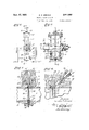
Fig. l is a side elevation of an orice meter iitting embodying the features of the present invention. Fig. 2 is a vertical detailed sectional view of the tting, being a View taken as indicated by line 2 2 on Fig. l. Fig. 3 is an enlarged vertical or transverse sectional view of the lower portionrv of the fitting, being a View taken as indicated by line 3--3 on Fig.k 2'. Fig. 4 is an enlarged fragmentary sectional view illustrating the carrier and disc-retaining means and` one of the clamping units embodiedY in the invention. Fig. 5 5 is an enlarged face or end elevation of the disc carrier. Fig. 6 is an enlarged end View of the disc-retaining ring. Fig. 7 is an end elevation of the assembly of the carrier, orifice disc, and retaining ring, and Fig. 8 is an enlarged detailed 10 sectional view of the assembly, being a View taken as indicated by line 8-8 on Fig. 7.
"The means or' construction provided by the present invention for removably retaining and for sealing about an orice disc may be employed 15 in connection with or embodied in orificeineter fittings of various types and classes. Throughout thefollowing detailed disclosure the invention will be described as embodied in the more or less typical forniof orifice meter fitting illustrated in 20 the drawings, it being understood that the invention is not to be taken as limited or restricted to the specic form or application about to be described, but that it is to be taken as including any features or modications that may fall within 25 the scope of the claims.
The general orifice meter construction illustrated in the drawings includes, generally, a housing or body IIJ having a iluid passage ll and a chamber I2 intersecting the fluidpassage, a plug 30 t3 for sealing between the iluid passage li and the principal parts of the chamber i2, and various other parts common to devices of this character;
The body I0 has a lower portion I@ that is 3 cylindrical in its general conguration and that is provided with the longitudinal uid passage II. Flanges I5'a are provided at the opposite ends of the body part I6 to facilitate connection of the ntting' in a pipe line. The chamber i2 40 is providedV in a projecting neck l5 of the body. The neck I5 is shown integral with the body and projects laterally or upwardly from the body portion I4. The neck I5 and its chamber l2 are substantially rectangular in horizontal cross sec- 15 tion, and the upper end of the chamber is closed by a removable head or cover plate I6.
TheV chamber'IZ is provided to carry and pass the orifice disc carrier, and its lower end comr municates with or intersects the huid passage I I. The lower end portion of the chamber I2 at the fluidpassage II is of reduced width, as illustrated in Fig. 3 of the drawings, and has spaced paralle] side walls. An annular seat II is provided U on onev wall of the chamber I2 around the fluid d CFI passage II. The seat I1 is flat and regular, being in the nature of a sealing face, and completely surrounds the fluid passage II.
The plug I3 is operatable to close olf or seal off the upper portion of the chamber I2 from the fluid passage II. The plug I3 is rotatable in a transverse horizontal opening I8 intersecting the chamber I2 at a point above the fluid passage I I. The opening I8 is of sufficient diameter to have opposite wall parts at the opposite sides of the chamber I2, as clearly illustrated in Fig. 3 of the drawings. The closing plug I3 and the opening I8 are longitudinally tapered to provide for the effective sealing of the plug with the walls of the opening. A transverse opening or slot I9 is provided in the plug I3 to pass the orifice disc carrier, as will be subsequently described. The plug I3 is rotatable between a position where the opposite ends of the slot I9 are closed by the walls of the opening I8 and a position where the slot I9 is in vertical central alignment with the chamber I2 to permit the passage of the disc carrier through the plug. The large end of the plug I3 projects horizontally from the neck I5 and has a polygonal portion 20 to facilitate its operation. Suitable means 2I is provided at the large end of the plug I3 to hold lt in sealing engagement with the walls of the opening I8 and to prevent the leakage of fluid from around the plug. Suitable packing means and back-off means 22 is provided at the small end of the plug I3.
The present invention is concerned primarily with the orifice disc for arrangement across the fluid passage II, with the carrier for the orifice disc, and with the means for holding the disc in operative position across the fluid passage and for sealing about the disc when in the operative position. The construction provided by the invention includes, generally, a carrier 23 movable between a position at the fluid passage II and a position in the upper end of the chamber I2, an orifice plate or disc 24, means 25 for removably holding the disc 24 in the carrier 23, and means 26 for clamping against the carrier 23 to provide for a fluid tight seal between the disc 24 and the carrier 23 and for a fluid tight seal between the disc 23 and for a fluid seal between the disc 24 and the body I0.
The carrier 23 is provided to hold and support the orifice disc 24. The carrier 23 is substantially rectangular in side elevation and is proportioned to have free movement vertically through the chamber I2. A central opening 21 is provided in the carrier 23 to register with the fluid passage I I when the parts are in their normal positions and to carry the orifice disc 24. The opening 21 is round to correspond with the configuration of the fluid passage II and is enlarged on one side to form a recess 28. An annular axially-facing shoulder 29 occurs between the end portion of the opening 21 and the recessed end portion 28. The shoulder 29 is in the nature of a sealing face for cooperating with or receiving the orice disc 24 as will be hereinafter described, and is preferably flat and regular.
In accordance with the broader aspects of the invention, the carrier 23 may be operated through the chamber I2 in any suitable manner. In the particular case illustrated in the drawings, a manually-operatable rod or stem 30 is provided for shifting the carrier 23. The stem 30 extends vertically through a packing gland 3| in the cap I5 to project into the chamber I2. The lower end of the stem 30 is screw threaded so that it may be threaded into a socket 32 in the upper end of the carrier 23. During normal use or operation of the fitting, the stem 30 is disconnected from the carrier 23 and has its lower end disposed within the upper portion of the chamber I2 so that the plug I3 may be in the closed position where it seals off the upper end of the chamber from the fluid passage Il. When it is desired to shift the carrier 23 to replace the orifice disc, the plug I3 is turned until the slot I9 is vertical so that the end of the stem 30 may be threaded into the socket 32 and the carrier 23 then be pulled upwardly through the slot into the upper end of the chamber I2.
Means are provided for properly centering the carrier 23 in the lower end of the chamber I2 so that its opening 21 is co-axial with the uid passage II. Spaced feet 33 are provided on the lower end of the carrier 23 to engage the lower end of the chamber I2. Guide screws 34, or the like, are provided on the side walls of the chamber I2 to slidably engage the side edges of the carrier 23. The feet 33 and the guide members 34 are adapted to maintain the carrier 23 in a position where its opening 21 is in true register with the fluid passage II. A screw 35 may be provided to engage the lower end of the carrier 23 and break it loose from its normal position in the event that it becomes set or immovable.
The orifice plate or disc 24 is adapted to be supported by the carrier 23 to extend across the fluid passage II and cause a differential in fluid on the fluid at opposite sides of the disc. The orifice disc 24 is proportioned to extend into the enlarged portion 28 of the opening in the carrier and to seat against the shoulder 29. The opposite sides of the orifice disc 24 are preferably flat and parallel, as illustrated in the drawings. A central opening 36 of the desired size is provided in the disc 24.
The means 25 for removably or detachably holding the disc 24 in the carrier 23 comprises a single retaining and sealing ring 31. The ring 31 is adapted to flt in the enlarged portion 28 of the opening in the carrier to engage a side of the orifice disc 24. In accordance with the preferred form of the invention, the opposite sides of the ring 31 are at and normal to the axis of the ring and are in the nature of sealing faces. The internal diameter of the sealing and retaining ring 31 is preferably the same as that of the fluid passage I I. The ring 31 is proportioned and shaped to readily fit into the enlarged part 28 of the carrier opening and to project from the side of the carrier 23 when in the retaining position against the disc 24. Both of the outer corners of the ring 31 are beveled to facilitate the arrangement of the ring in the opening 28.
The invention includes means for releasably holding the ring 31 in its retaining position. Projections or lugs 38 project from the periphery of the retaining ring 31 at diametrically opposite points. The lugs 38 may be in the nature of the heads of rivets passed through radial openings in the ring 31, as illustrated throughout the drawings. In the preferred construction, the lugs 38 are rounded or substantially semi-spherical. The enlarged portion 28 of the carrier opening is under cut or provided with an annular groove 39 to receive the lugs 38. A notch or notches 40 are provided in the carrier 23 to pass a lug or lugs 38 into the groove 39. In the embodiment of the invention illustrated throughout the drawings, a single notch 4D is provided in the carrier 23 at the upper end of the opening 28.
To position the ring 31 in its retaining position, it is first arranged with its lower portion in the lower part of the opening 23 so that one of the lugs 3S extends into the groove 39. The ring may then be tilted toward the carrier 23 so that the other lug 33 is passed through the notch dal into the groove 39. A partial turn or rotation of the ring 31 to move the uppermost lug 38 out f register with the notch 43 locks the ring 31 in the carrier. It is an important feature of the invention that the lug-receiving groove 39 is of sufficient axial length to allow for axial movement of the ring 31, so that the end of the ring may effectively seat against the orifice disc 24 to seal with the disc and hold the disc against the shoulder 29. In the particular case illustrated in the drawings, the groove 39 extends axially inward to a point approximately at the outer edge of the disc 2t. The lugs 33 are equally spaced between the opposite ends of the ring 31 so that the ring 31 may be arranged with either of its ends toward or against the orice disc 24. It is to be understood that the orifice disc 2d is to be arranged in the carrier 23 and that the ring 31 is to be assembled in its retaining position when the carrier 23 is at the exterior of the fitting body i6. An axial groove lll is provided at the outer edge of the shoulder 23. The groove 4! and the beveied corner of the ring 31 are adapted to receive any burrs or irregularities on the outer corner of the disc 21% to permit the effective sealing engagement of the plate 2Q with the shoulder 29 and the ring 31 with the plate.
The means 2b is provided to act on or clamp against an end of the carrier 23 to force and clamp the retaining and sealing ring 31 against the seat i 1 and, accordingly, to clamp the peripheral edge portions of the orice disc 2d between ie sealing shoulder 29 and the ring 31. The means 23 is in the nature of a screw means and includes a plurality of like clamping units provided at circumferentially spaced points on the cylindrical portion i4 of the body. The several clamping units are alike, and each includes a tubular plug 5 screw threaded into an opening Se in the body part I4, and a clamping screw threaded through the plug. The openings @t are inclined at suitable angles to the vertical and horizontal, and each has an inner portion of reduced diameter communicating with the chamber l2. The plugs d are screw threaded into the outer portions of the openings lb and project outwardly from the body part la.
The clamping screws 41 are threaded through the plugs '-35 and extend through the openings d6 to project into the chamber I2 and engage a side of the carrier 23. The outer ends of the clamping screws 41 project from the plugs 45 and are polygonal to facilitate the turning of the screws. Suitable packing glands 43 are provided on the outer ends of the plugs #l5 to seal about the clamping screws d1. Each screw d1 is provided with a sealing collar 33 which is adapted to either cooperate with a sealing shoulder 53 in the opening 43 or a sealing face 5l on the inner end of the plug t5. The sealing collars 69 of the screws l1 may be brought into engagement with either the shoulders E@ or the faces 5l to provide a seal between the clamping screws and the plugs during shifting of the carrier 23 and/or during repacking of the glandsv d8. The screws 41 are adapted to be threaded against the carrier 23 to force the ring 31 against the seat I1 and thus clamp the disc 24 between the shoulder 29 and the ring 31. The screws ll1 are adapted to exert a suitable pressure on the carrier 23 to provide for the effective sealing engagement of the disc 24 with the shoulder 29 and of the ring 31 with the disc and the seat I1. It will be apparent that the screws 31 may be threaded outwardly to disengage from the carrier 23 and permit the carrier 23 to be operated upwardly through the chamber l2.
It is believed that the utility and practicability of the construction provided by the present invention will be readily apparent from the foregoing detailed description. The orifice disc 24 may be easily positioned in the opening of the carrier 23, and the retaining and sealing ring 31 is readily arranged in its retaining position. The ring 31 operates to hold the orifice disc 24 in the carrier 23 during the operation of the carrier through the chamber I2. After the carrier 23 has been lowered through the chamber I2 to its operative position at the fluid passage H, the stem 3@ may be threaded out of the socket 32 and drawn upwardly so that the plug i3 may be operated to the closed position. When the carrier 'se' has been properly set in the lower end of the chamber l2, the clamping screws 41 may be threaded inwardly to clamp against the side of the carrier 23. The clamping of the screws 41 against the carrier brings the outer end of the ring 31 into sealing engagement with the seat l1 and clamps the orice disc 2d between the ring and the shoulder 29. As the opposite ends of the ring 31 are in the nature of sealing faces, the ring is adapted to form an effective fluid tight seal between the shoulder l1 and the disc 2&3. The clearance of the lugs 38 in the groove 39 allows the sealing and retaining ring 31 to properly center itself and seal with the seat I1 and the disc 24. The ring 31 cooperates with the seat I1 to prevent the leakage of the fluid between the carrier 23 and the walls of the chamber l2, while the plate 24 is tightly clamped between the sealing shoulder 29 and the ring 31, so that leakage of fluid around the plate is prevented. It is to be noted that the present invention provides an orifice meter fitting construction wherein a single simple ring operates to releasably hold the orice plate or disc in position in the carrier and also operates to provide a fluid seal between the orice disc and the seat in the body of the fitting. The ring 31 may be easily and quickly arranged in and detached from the carrier and does not involve any packing or screw threads.
Having described only a typical preferred form of my invention, I do not wish to limit myself to the specific details set forth, but wish to reserve to myself any changes or variations that may appear to those skilled in the art or fall within the scope of the following claims.
Having described my invention, I claim:
l. In an orice meter fitting, a body having a uid passage, a seat in the body around the passage, a carrier in the body, a disc supported by the carrier to extend across the passage, a removable member retaining the plate in the carrier and adapted to seal with both the seat and the disc, and means acting through the carrier for clamping the member against the seat and for clamping the disc against the member.
2. A device of the character described including, a body having a fluid passage and a chamber intersecting the passage, a seat in the body around the passage, a shiftable carrier in the chamber having an opening to register with the passage, an axially facing shoulder in the opening, a disc in the opening adapted to seal against the shoulder, a ring having limited play in the opening and adapted to seal with both the seat and disc, and means for clamping the ring and disc togethehr between the seat and shoulder.
3. A device of the character described including, a body having a fluid passage and a charnber intersecting the passage, a seat in the body around the passage, a shiftable carrier in the chamber having an opening to register with the passage, an axially facing shoulder in the opening, a plate in the opening adapted to seal against the shoul-der, a removable retaining ring in the opening adapted to have axial play in the opening so as to bear against the plate, and means for clamping the ring and plate together between the seat and shoulder to form a fluid-tight seal between the seat and shoulder.
4. A device of the character described including, a body having a uid passage and a chamber intersecting the passage, a seat on a wall of the chamber around the passage, a carrier movsealing with the other face of the plat-e and projecting from the carrier to seal with the said seat.
5. A device of the character described including, a body having a uid passage and a chamber intersecting the passage, a seat on a wall of the chamber around the passage, a carrier movabl-e in the chamber between a position at the passage, and a position removed from the passage, the carrier having an opening adapted to register with the passage, a sealing shoulder in the opening facing the seat, a removable plate in the opening having sealing faces on its opposite sides, one of said faces being adapted to cooperate with th-e shoulder, a sealing ring in the opening for sealing with the other face of the plate and projecting from the carrier to seal with the seat, and a releasable lug and slot connection between the sealing ring and the carrier whereby the sealing ring detachably retains the plate in the opening but is free to be forced inward against the plate.
6. A device of the character described including, a body having a iiuid passage and a chamber intersecting the passage, a seat in the body around the passage, a shiftable carrier in the chamber having an opening to register with the passage, an axially facing shoulder in the opening, a plate in the opening adapted to seal against the shoulder, a sealing ring removably holding the plate in the opening and projecting from the carrier toward the seat, a lug and slot connection between the ring and carrier holding the ring against outward movement in the opening and allowing inward movement of the ring and a plurality of spaced screws on the body for urging the carrier toward the seat to clamp the ring against the seat and to clamp the plate between the ring and should-er.
7. In a device of the character described, a shiftable carrier having an opening, an axially facing shoulder in the opening, a removable orifice plate in the opening adapted to seal against said shoulder, a removable ring in the opening for retaining the plate in the opening, the ring projecting from the carrier, and releasable means holding the ring against outward movement, the ring being free to move inwardly whereby it may seal against the plate.
8. A device of the character described including, a body having a uid passage and a chamber intersecting the passage, a seat in the body around the passage, a shiftable carrier in the chamber having an opening to register with the passage, an axially facing shoulder in the opening, a plate in the opening adapted to seal against the shoulder, a removable ring retaining the plate in the opening and projecting from the carrier toward the seat, means releasably holding the ring against outward movement, the ring being free to move inwardly to seal against the plate, and means on the body releasably 25 clamping the ring and plate together between the seat and should-er.
9. A device of the character described including, a body having a fluid passage and a chamber intersecting the passage, a seat in the body around the passage, a shiftable carrier in the chamber having an opening to register with the passage, an axially facing shoulder in the opening, a plate in the opening adapted to seal against the shoulder, a sealing ring removably holding the plate in the opening and projecting from the carrier toward the seat, means releasably holding the ring against outward movement, the ring being free to mov-e inwardly to seal against the plate, and a screw on the body for 40 urging the carrier toward the seat to clamp the ring against the seat and to clamp the plate between the ring and shoulder.
l0. In a device of the character described, a
shiftable carrier having an opening, an axially 45 facing shoulder in the opening, a removable orice plate in the opening adapted to seal against said shoulder, a ring in the opening removably mounted upon the carrier and serving to normally retain the plate in the opening but upon removal of the ring enabling the plate to be removed, said ring being so mounted upon the carrier as to enable its being forced axially against the plate upon the application of axial pressure to force the plate against the shoulder 55 whereby upon the application of axial pressure 65 said means may be forced axially against the plate and force the plate against the shoulder to effect a seal, said means when in plate retaining position projecting outwardly beyond the face of the carrier. 7
GORDON Z. GREENE.
Priority Applications (1)
| Application Number | Priority Date | Filing Date | Title |
|---|---|---|---|
| US563542A US2014682A (en) | 1931-09-18 | 1931-09-18 | Orifice meter fitting |
Applications Claiming Priority (1)
| Application Number | Priority Date | Filing Date | Title |
|---|---|---|---|
| US563542A US2014682A (en) | 1931-09-18 | 1931-09-18 | Orifice meter fitting |
Publications (1)
| Publication Number | Publication Date |
|---|---|
| US2014682A true US2014682A (en) | 1935-09-17 |
Family
ID=24250921
Family Applications (1)
| Application Number | Title | Priority Date | Filing Date |
|---|---|---|---|
| US563542A Expired - Lifetime US2014682A (en) | 1931-09-18 | 1931-09-18 | Orifice meter fitting |
Country Status (1)
| Country | Link |
|---|---|
| US (1) | US2014682A (en) |
Cited By (14)
| Publication number | Priority date | Publication date | Assignee | Title |
|---|---|---|---|---|
| US2448071A (en) * | 1944-08-12 | 1948-08-31 | Bert E Anderson | Orifice exchanger |
| US2462493A (en) * | 1944-07-19 | 1949-02-22 | Paul A Dewhirst | Seal for pipe-line fittings |
| US2687748A (en) * | 1951-07-30 | 1954-08-31 | Daniel Orifice Fitting Company | Orifice plate assembly |
| US2743742A (en) * | 1952-07-14 | 1956-05-01 | Robinson Orifice Fitting Compa | Line blind |
| US3891146A (en) * | 1973-09-12 | 1975-06-24 | Advance Value Installations In | Pipeline apparatus |
| US5094272A (en) * | 1990-06-11 | 1992-03-10 | Foster James H | Adjustable orifice plate seal |
| US5181542A (en) * | 1991-02-22 | 1993-01-26 | Daniel Industries, Inc. | Orifice system mounting assembly |
| US5327938A (en) * | 1992-11-20 | 1994-07-12 | Crane Manufacturing, Inc. | Adjustable orifice fitting carrier for a pipeline orifice fitting |
| US5588467A (en) * | 1995-03-15 | 1996-12-31 | Crane Manufacturing, Inc. | Orifice fitting |
| US5758692A (en) * | 1995-03-15 | 1998-06-02 | Crane Manufacturing, Inc. | Orifice fitting |
| US5778933A (en) * | 1995-03-15 | 1998-07-14 | Crane Manufacturing, Inc. | Orifice fitting |
| US5836356A (en) * | 1996-03-12 | 1998-11-17 | Mueller Steam Specialty, A Divison Of Core Industries, Inc. | Dual chamber orifice fitting |
| US20050258387A1 (en) * | 2004-05-19 | 2005-11-24 | Daniel Industries, Inc. | Dual chamber orifice fitting plate support |
| US20070235679A1 (en) * | 2006-04-06 | 2007-10-11 | Tmco, Inc. | Dual chamber orifice fitting |
-
1931
- 1931-09-18 US US563542A patent/US2014682A/en not_active Expired - Lifetime
Cited By (21)
| Publication number | Priority date | Publication date | Assignee | Title |
|---|---|---|---|---|
| US2462493A (en) * | 1944-07-19 | 1949-02-22 | Paul A Dewhirst | Seal for pipe-line fittings |
| US2448071A (en) * | 1944-08-12 | 1948-08-31 | Bert E Anderson | Orifice exchanger |
| US2687748A (en) * | 1951-07-30 | 1954-08-31 | Daniel Orifice Fitting Company | Orifice plate assembly |
| US2743742A (en) * | 1952-07-14 | 1956-05-01 | Robinson Orifice Fitting Compa | Line blind |
| US3891146A (en) * | 1973-09-12 | 1975-06-24 | Advance Value Installations In | Pipeline apparatus |
| US5094272A (en) * | 1990-06-11 | 1992-03-10 | Foster James H | Adjustable orifice plate seal |
| US5181542A (en) * | 1991-02-22 | 1993-01-26 | Daniel Industries, Inc. | Orifice system mounting assembly |
| US5419372A (en) * | 1991-02-22 | 1995-05-30 | Daniel Ind Inc | Orifice system mounting assembly |
| US5327938A (en) * | 1992-11-20 | 1994-07-12 | Crane Manufacturing, Inc. | Adjustable orifice fitting carrier for a pipeline orifice fitting |
| US5758692A (en) * | 1995-03-15 | 1998-06-02 | Crane Manufacturing, Inc. | Orifice fitting |
| US5588467A (en) * | 1995-03-15 | 1996-12-31 | Crane Manufacturing, Inc. | Orifice fitting |
| US5778933A (en) * | 1995-03-15 | 1998-07-14 | Crane Manufacturing, Inc. | Orifice fitting |
| US5836356A (en) * | 1996-03-12 | 1998-11-17 | Mueller Steam Specialty, A Divison Of Core Industries, Inc. | Dual chamber orifice fitting |
| US20050258387A1 (en) * | 2004-05-19 | 2005-11-24 | Daniel Industries, Inc. | Dual chamber orifice fitting plate support |
| WO2005116458A2 (en) * | 2004-05-19 | 2005-12-08 | Daniel Industries, Inc. | Dual chamber orifice fitting plate support |
| WO2005116458A3 (en) * | 2004-05-19 | 2007-06-07 | Daniel Ind Inc | Dual chamber orifice fitting plate support |
| US20100229988A1 (en) * | 2004-05-19 | 2010-09-16 | Daniel Measurement And Control, Inc. | Dual Chamber Orifice Fitting Plate Support |
| US7837176B2 (en) * | 2004-05-19 | 2010-11-23 | Daniel Measurement And Control, Inc. | Dual chamber orifice fitting plate support |
| US8167268B2 (en) * | 2004-05-19 | 2012-05-01 | Daniel Measurement And Control, Inc. | Dual chamber orifice fitting plate support |
| US20070235679A1 (en) * | 2006-04-06 | 2007-10-11 | Tmco, Inc. | Dual chamber orifice fitting |
| US8459305B2 (en) | 2006-04-06 | 2013-06-11 | Tmco, Inc. | Dual chamber orifice fitting |
Similar Documents
| Publication | Publication Date | Title |
|---|---|---|
| US2014682A (en) | Orifice meter fitting | |
| US3005468A (en) | Rotary sleeve valves | |
| US3305211A (en) | Stressed plastic valve for laboratory glassware | |
| US2033371A (en) | Sealing device | |
| US2237476A (en) | Apparatus for fluid control | |
| US1890011A (en) | Coupling device | |
| US3172282A (en) | Anti-tampering cut-off valve cover | |
| US2482687A (en) | Service tau | |
| US1957807A (en) | Orifice meter fitting | |
| US4144909A (en) | Apparatus for closing side openings into pipelines | |
| US1808715A (en) | reynolds | |
| US2271138A (en) | Line blind | |
| US2312341A (en) | Packed swivel joint | |
| US2310351A (en) | Stopper for pipes | |
| US2616655A (en) | Gate valve | |
| US3857414A (en) | Internal threaded fitting connector | |
| US3604591A (en) | Quick action plugging device | |
| US1854051A (en) | Waterworks tap | |
| US2515260A (en) | Combined tap and valve | |
| US1911455A (en) | Removable closure | |
| US2188607A (en) | Method of making lateral extensions from pipe lines | |
| US2011082A (en) | Orifice meter fitting | |
| US2636514A (en) | Tank plug | |
| US1381598A (en) | Spigot | |
| US2154498A (en) | Expanding pipe plug |