US20140327432A1 - Micro inductive sensor - Google Patents
Micro inductive sensor Download PDFInfo
- Publication number
- US20140327432A1 US20140327432A1 US14/269,871 US201414269871A US2014327432A1 US 20140327432 A1 US20140327432 A1 US 20140327432A1 US 201414269871 A US201414269871 A US 201414269871A US 2014327432 A1 US2014327432 A1 US 2014327432A1
- Authority
- US
- United States
- Prior art keywords
- coil
- coupler
- package
- receiving
- sensor assembly
- Prior art date
- Legal status (The legal status is an assumption and is not a legal conclusion. Google has not performed a legal analysis and makes no representation as to the accuracy of the status listed.)
- Granted
Links
Images
Classifications
-
- G—PHYSICS
- G01—MEASURING; TESTING
- G01D—MEASURING NOT SPECIALLY ADAPTED FOR A SPECIFIC VARIABLE; ARRANGEMENTS FOR MEASURING TWO OR MORE VARIABLES NOT COVERED IN A SINGLE OTHER SUBCLASS; TARIFF METERING APPARATUS; MEASURING OR TESTING NOT OTHERWISE PROVIDED FOR
- G01D5/00—Mechanical means for transferring the output of a sensing member; Means for converting the output of a sensing member to another variable where the form or nature of the sensing member does not constrain the means for converting; Transducers not specially adapted for a specific variable
- G01D5/12—Mechanical means for transferring the output of a sensing member; Means for converting the output of a sensing member to another variable where the form or nature of the sensing member does not constrain the means for converting; Transducers not specially adapted for a specific variable using electric or magnetic means
- G01D5/14—Mechanical means for transferring the output of a sensing member; Means for converting the output of a sensing member to another variable where the form or nature of the sensing member does not constrain the means for converting; Transducers not specially adapted for a specific variable using electric or magnetic means influencing the magnitude of a current or voltage
- G01D5/20—Mechanical means for transferring the output of a sensing member; Means for converting the output of a sensing member to another variable where the form or nature of the sensing member does not constrain the means for converting; Transducers not specially adapted for a specific variable using electric or magnetic means influencing the magnitude of a current or voltage by varying inductance, e.g. by a movable armature
- G01D5/204—Mechanical means for transferring the output of a sensing member; Means for converting the output of a sensing member to another variable where the form or nature of the sensing member does not constrain the means for converting; Transducers not specially adapted for a specific variable using electric or magnetic means influencing the magnitude of a current or voltage by varying inductance, e.g. by a movable armature by influencing the mutual induction between two or more coils
- G01D5/2066—Mechanical means for transferring the output of a sensing member; Means for converting the output of a sensing member to another variable where the form or nature of the sensing member does not constrain the means for converting; Transducers not specially adapted for a specific variable using electric or magnetic means influencing the magnitude of a current or voltage by varying inductance, e.g. by a movable armature by influencing the mutual induction between two or more coils by movement of a single coil with respect to a single other coil
Definitions
- This invention relates generally to position sensors. More particularly, this invention relates to inductive position sensors.
- Position sensors are often used in various mechanical control systems. Common position sensors include capacitive sensors, potentiometer sensors, and magnetic position sensors. However, inductive sensors are one of the most commonly used position sensors in vehicles. Inductive sensors detect the position of a target by measuring the mutual inductance between the target and the sensing coil. Compared to other magnetic position sensors, inductive sensors are more cost effective because they do not need a magnet and instead use an electromagnetic coil.
- Inductive sensors are also desirable to use in vehicles instead of magnetic type sensors because inductive sensors are generally more reliable. Magnetic sensors can suffer performance loss as the magnet degrades and are more sensitive to magnetic disturbances from the surrounding environment. In contrast, inductive sensors are not dependent upon magnets and are more tolerant of interference from common automotive devices such as electric motors and alternators. However, to ensure adequate signal strength, inductive sensors are generally larger than traditional magnetic sensors. Consequently, inductive sensors also produce greater amounts of magnetic emissions due to their larger antenna area.
- Embodiments of the present invention include a sensor package and a coupler package.
- the sensor package includes a plurality of pins, a signal processor, an integrated capacitor, a ferrite layer, a transmitter coil, a two part receiving coil, and a plurality of discrete components.
- the coupler package includes an integrated capacitor, a ferrite layer, and a coupler coil.
- the transmitter coil in the sensor package is energized by an external power source which in turn energizes the coupler coil in the coupler package.
- the sensor measures the rotational position of the coupler package relative to the sensor package by detecting and measuring with the two part receiving coil the signal returned by the coupler coil.
- the signal processor calculates the position of the coupler package relative to the sensor package by comparing the coupling factors between the coupler package and the sensor package.
- the present invention uses a resonator as the coupler.
- a resonator as the coupler allows the transmitter coil and the coupler to become an oscillator system with a much higher quality factor (Q factor) than a conventional inductive sensor.
- Q factor quality factor
- the ferrite layer of the sensor package and the coupler package allows the size of the coils to be significantly reduced relative to conventional inductive sensors.
- the eddy current on the coupler is the direct source of the signal on the two part receiving coil.
- the resonator coupler When subjected to the same magnetic field as a conventional coupler, the resonator coupler will generate more eddy current. Therefore, using the same driving power, an inductive sensor using a resonator as the coupler can generate a much stronger electromagnetic field on the receiving coil than a conventional inductive sensor.
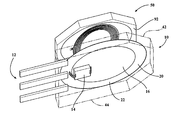
- FIG. 1 illustrates a perspective view of the inductive sensor including the sensor package and the coupler package
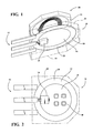
- FIG. 2 illustrates a bottom side view of the sensor package
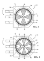
- FIG. 3 illustrates a top side view of the sensor package and the two part transmitter coil according to a first embodiment
- FIG. 4 illustrates a top side view of the sensor package and the two part transmitter coil according to a second embodiment
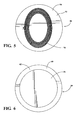
- FIG. 5 illustrates a bottom side view of the coupler package
- FIG. 6 illustrates a top side view of the coupler package.
- Embodiments of the present invention include a sensor package 10 and a coupler package 50 .
- the sensor package 10 includes a plurality of pins 12 , a signal processor 14 , an integrated capacitor 16 , a ferrite layer 20 , a transmitter coil 22 , a two part receiving coil 30 , and a plurality of discrete components 48 .
- the coupler package 50 includes an integrated capacitor 56 , a ferrite layer 60 , and a coupler coil 70 .
- the transmitter coil 22 in the sensor package 10 is energized by an external power source (not shown) which in turn energizes the coupler coil 70 in the coupler package 50 .
- the sensor 10 measures the rotational position of the coupler package 50 relative to the sensor package 10 by detecting and measuring with the two part receiving coil 30 the signal returned by the coupler coil 70 .
- the signal processor 14 calculates the position of the coupler package 50 relative to the sensor package 10 by comparing the coupling factors between the coupler package 50 and the sensor package 10 .
- the sensor assembly of the present invention including the sensor package 10 and the coupler package 50 are generally shown in FIG. 1 .
- the inductive sensor and sensor package 10 of the present invention features a miniaturized design that can be fit into a single package due to enhanced signal strength.
- the sensor package 10 has a top side 42 , which faces a bottom side 92 of the coupler package 50 , and an opposite bottom side 44 .
- a ferrite layer 20 extends substantially throughout the sensor package 10 and has a generally circular shape, although other shapes according to the sensor package 10 and coils 22 , 30 are also possible.
- a signal processor 14 is also found on the bottom 22 of the ferrite layer 20 .
- the signal processor 14 measures and processes the signals produced and received by the sensor package 10 .
- the signal processor 14 is also connected to the pins 12 which transmit the various signals of the sensor package 10 .
- the transmitter coil 22 and the two part receiving coil 30 are on the top side 42 of the sensor package 10 .
- the transmitter coils 22 shown in FIGS. 3 and 4 are generally circular and concentric with the ferrite layer 20 about an axis of the transmitter coil 22 .
- the transmitter coil 22 has a plurality of windings which may be adjusted as necessary according to design parameters.
- the transmitter coil 22 is shown having a circular shape, although other embodiments are possible without departing from the scope of the invention.
- the two part receiving coil 30 is shown in FIGS. 3 and 4 residing inside an inner diameter of the transmitter coil 22 on the top side of the sensor package 10 .
- the two part receiving coil 30 of the sensor package 10 has a first receiver coil 32 and a second receiver coil 36 .
- the first receiver coil 32 has N loops wound in a first direction.
- the first receiver coil loops 32 a - d are arranged about the central axis of the transmitter coil 22 and within the inner diameter of the transmitter coil 22 .
- the first receiver coil loops 32 a - d are spaced about the transmitter coil 22 axis by 360/N degrees.
- N 4 first receiver coil loops 32 a - d and therefore each loop 32 a - d of first receiver coil 32 is spaced apart from the adjacent first receiver coil 32 loop 32 a - d by 90 degrees.
- the second receiver coil 36 also has N loops 36 a - d which are wound in a direction opposite to the first receiver coil 32 .
- Each of the second receiver coil loops 36 a - d are angularly spaced by 360/N degrees about the transmitter coil 22 axis relative to the adjacent second receiver coil loop 36 a - d .
- the second receiver coil loops 36 a - d are also angularly offset from adjacent first receiver coil loops 32 a - d by 180/N degrees and vice versa.
- the circular area inside the transmitter coil 22 is divided angularly into 2N sections. Proceeding angularly about the transmitter coil 22 axis, the two part receiving coil 30 sections alternate between loops 32 a - d of the first receiver coil 32 and loops 36 a - d of the second receiver coil 36 .
- the loops 32 a - d of the first receiver coil 32 are wound in a first direction while the loops 36 a - d of the second receiver coil 36 are wound in an opposite second direction.
- loops 32 a - d of the first receiver coil 32 are only adjacent to loops 36 a - d of the second receiver coil 36 and loops of the first 32 and second receiver coils 36 are angularly offset from one another by 180/N degrees.
- each loop 32 a - f of first receiver coil 32 is spaced apart from the adjacent first receiver coil 32 loop 32 a - f by 60 degrees.
- N loops of the first receiver coil 32 and second receiver coil 36 can be similarly adjusted to include different numbers of N sections.
- the coupler package 50 has a ferrite layer 60 having a top side 62 and a bottom side 66 .
- the ferrite layer 60 has an integrated capacitor 56 on the top side 62 and a noncircular coupler coil 70 on the bottom side 66 .
- the bottom side 66 of the ferrite layer 60 of the coupler package 50 faces the top side 42 of the sensor package 10 .
- the integrated capacitor 56 of the coupler package 50 shown in FIG. 6 is circular; however, this shape is exemplary and other arrangements are possible.
- the noncircular coupler coil 70 is made from a plurality of windings and dimensioned so that when aligned about the axis of the transmitter coil 22 of the sensor package 10 , the coupler coil 70 overlies at least a portion of both the first 32 and second receiver coil 36 loops 32 a - d , 36 a - d.
- the coupler coil 70 shown in FIG. 5 has a generally oval shape; however, the coupler coil 70 is not limited to this shape alone.
- the coupler coil 70 of the coupler package 50 is aligned about the axis of the transmitter coil 22 and the sensor package 10 , the coupler coil 70 will overlie at least a portion of both the first and second receiver coil loops 32 a - d , 36 a - d.
- the portion of the coupler coil 70 overlapping the first and second receiver coil loops 32 a - d , 36 a - d changes. This in turn changes the amount of coupling factor between the coupler package 50 and each of the first receiver coil 32 and second receiver coil 36 .
- the processor 14 uses the signals measured by the two part receiving coil 30 to generate an output signal representative of the rotational position of the coupler package 50 relative to the sensor package 10 .
- ferrite layers 20 , 60 in both the sensor 10 and coupler packages 50 focuses the electromagnetic fields and keeps the energy in local space. The electromagnetic energy is therefore used more efficiently by the sensor 10 to generate the signal. Furthermore, the combination of the ferrite layers 20 , 60 and the integrated capacitors 16 , 56 provide electromagnetic shielding to the sensor 10 and coupler packages 50 which reduces the negative effects of electromagnetic interference from other components. In this way, the overall size of the sensor package 10 and the coupler package 50 can be minimized.
- PCBs printed circuit boards
- the transmitter coil 22 and two part receiving coil are fabricated on a first PCB as is known to those skilled in the art.
- the coupler coil 70 is fabricated on a second PCB.
- a first ferrite disc 20 is arranged on a bottom side of the first PCB and a second ferrite disc is arranged on a top side of the second PCB.
- the ferrite discs, PCBs, and additional components are then disposed within a housing. In this way, PCBs and ferrite discs are used to form the sensor package 10 and the coupler package 50 .
- the present invention provides a micro inductive rotary position sensor able to generate an output signal representative of the rotational position of the coupler package relative to the sensor package. Furthermore, both the sensor package and coupler package can be individually over molded in a plastic package.
- the coils may be fabricated by micro fabrication technology which includes, but is not limited to, sputtering, chemical vapor deposition, and electrodeposition. Using micro fabrication technology allows more coil turns to be built on a small area.
- the transmitter coil of the sensor package is shown concentrically wound around the first and second receiver loops; however, the present invention is not limited to this exemplary arrangement.
Landscapes
- Physics & Mathematics (AREA)
- General Physics & Mathematics (AREA)
- Transmission And Conversion Of Sensor Element Output (AREA)
- Arrangements For Transmission Of Measured Signals (AREA)
- Measurement Of Length, Angles, Or The Like Using Electric Or Magnetic Means (AREA)
Abstract
Description
- This application claims priority of U.S. Provisional Application 61/819,118 filed May 3, 2013, the contents of which are included herein by reference.
- This invention relates generally to position sensors. More particularly, this invention relates to inductive position sensors.
- Position sensors are often used in various mechanical control systems. Common position sensors include capacitive sensors, potentiometer sensors, and magnetic position sensors. However, inductive sensors are one of the most commonly used position sensors in vehicles. Inductive sensors detect the position of a target by measuring the mutual inductance between the target and the sensing coil. Compared to other magnetic position sensors, inductive sensors are more cost effective because they do not need a magnet and instead use an electromagnetic coil.
- Inductive sensors are also desirable to use in vehicles instead of magnetic type sensors because inductive sensors are generally more reliable. Magnetic sensors can suffer performance loss as the magnet degrades and are more sensitive to magnetic disturbances from the surrounding environment. In contrast, inductive sensors are not dependent upon magnets and are more tolerant of interference from common automotive devices such as electric motors and alternators. However, to ensure adequate signal strength, inductive sensors are generally larger than traditional magnetic sensors. Consequently, inductive sensors also produce greater amounts of magnetic emissions due to their larger antenna area.
- Embodiments of the present invention include a sensor package and a coupler package. The sensor package includes a plurality of pins, a signal processor, an integrated capacitor, a ferrite layer, a transmitter coil, a two part receiving coil, and a plurality of discrete components. The coupler package includes an integrated capacitor, a ferrite layer, and a coupler coil.
- The transmitter coil in the sensor package is energized by an external power source which in turn energizes the coupler coil in the coupler package. The sensor then measures the rotational position of the coupler package relative to the sensor package by detecting and measuring with the two part receiving coil the signal returned by the coupler coil. The signal processor calculates the position of the coupler package relative to the sensor package by comparing the coupling factors between the coupler package and the sensor package.
- In sharp contrast to conventional inductive sensors which use a metal piece as the fabricated coupler, the present invention uses a resonator as the coupler. Using a resonator as the coupler allows the transmitter coil and the coupler to become an oscillator system with a much higher quality factor (Q factor) than a conventional inductive sensor. Furthermore, the ferrite layer of the sensor package and the coupler package allows the size of the coils to be significantly reduced relative to conventional inductive sensors.
- The eddy current on the coupler is the direct source of the signal on the two part receiving coil. When subjected to the same magnetic field as a conventional coupler, the resonator coupler will generate more eddy current. Therefore, using the same driving power, an inductive sensor using a resonator as the coupler can generate a much stronger electromagnetic field on the receiving coil than a conventional inductive sensor.
-
FIG. 1 illustrates a perspective view of the inductive sensor including the sensor package and the coupler package; -
FIG. 2 illustrates a bottom side view of the sensor package; -
FIG. 3 illustrates a top side view of the sensor package and the two part transmitter coil according to a first embodiment; -
FIG. 4 illustrates a top side view of the sensor package and the two part transmitter coil according to a second embodiment; -
FIG. 5 illustrates a bottom side view of the coupler package; and -
FIG. 6 illustrates a top side view of the coupler package. - Embodiments of the present invention include a
sensor package 10 and acoupler package 50. Thesensor package 10 includes a plurality ofpins 12, asignal processor 14, an integratedcapacitor 16, aferrite layer 20, atransmitter coil 22, a twopart receiving coil 30, and a plurality ofdiscrete components 48. Thecoupler package 50 includes an integratedcapacitor 56, aferrite layer 60, and acoupler coil 70. Thetransmitter coil 22 in thesensor package 10 is energized by an external power source (not shown) which in turn energizes thecoupler coil 70 in thecoupler package 50. Thesensor 10 then measures the rotational position of thecoupler package 50 relative to thesensor package 10 by detecting and measuring with the twopart receiving coil 30 the signal returned by thecoupler coil 70. Thesignal processor 14 calculates the position of thecoupler package 50 relative to thesensor package 10 by comparing the coupling factors between thecoupler package 50 and thesensor package 10. - The sensor assembly of the present invention including the
sensor package 10 and thecoupler package 50 are generally shown inFIG. 1 . The inductive sensor andsensor package 10 of the present invention features a miniaturized design that can be fit into a single package due to enhanced signal strength. Thesensor package 10 has atop side 42, which faces abottom side 92 of thecoupler package 50, and anopposite bottom side 44. Aferrite layer 20 extends substantially throughout thesensor package 10 and has a generally circular shape, although other shapes according to thesensor package 10 andcoils - On the
bottom side 22 of theferrite layer 20 there is an integratedcapacitor 16 having a plurality ofdiscrete components 48. Thesediscrete components 48 can include capacitors, resistors, or other basic electronic components known in the art. Asignal processor 14 is also found on thebottom 22 of theferrite layer 20. Thesignal processor 14 measures and processes the signals produced and received by thesensor package 10. Thesignal processor 14 is also connected to thepins 12 which transmit the various signals of thesensor package 10. - The
transmitter coil 22 and the twopart receiving coil 30 are on thetop side 42 of thesensor package 10. Thetransmitter coils 22 shown inFIGS. 3 and 4 are generally circular and concentric with theferrite layer 20 about an axis of thetransmitter coil 22. Thetransmitter coil 22 has a plurality of windings which may be adjusted as necessary according to design parameters. Thetransmitter coil 22 is shown having a circular shape, although other embodiments are possible without departing from the scope of the invention. - The two
part receiving coil 30 is shown inFIGS. 3 and 4 residing inside an inner diameter of thetransmitter coil 22 on the top side of thesensor package 10. The twopart receiving coil 30 of thesensor package 10 has a first receiver coil 32 and a second receiver coil 36. The first receiver coil 32 has N loops wound in a first direction. In a first preferred embodiment shown inFIG. 3 , the first receiver coil loops 32 a-d are arranged about the central axis of thetransmitter coil 22 and within the inner diameter of thetransmitter coil 22. The first receiver coil loops 32 a-d are spaced about thetransmitter coil 22 axis by 360/N degrees. For example, as shown inFIG. 3 there are N=4 first receiver coil loops 32 a-d and therefore each loop 32 a-d of first receiver coil 32 is spaced apart from the adjacent first receiver coil 32 loop 32 a-d by 90 degrees. - The second receiver coil 36 also has N loops 36 a-d which are wound in a direction opposite to the first receiver coil 32. Each of the second receiver coil loops 36 a-d are angularly spaced by 360/N degrees about the
transmitter coil 22 axis relative to the adjacent second receiver coil loop 36 a-d. The second receiver coil loops 36 a-d are also angularly offset from adjacent first receiver coil loops 32 a-d by 180/N degrees and vice versa. - More simply, as shown in
FIG. 3 , the circular area inside thetransmitter coil 22 is divided angularly into 2N sections. Proceeding angularly about thetransmitter coil 22 axis, the twopart receiving coil 30 sections alternate between loops 32 a-d of the first receiver coil 32 and loops 36 a-d of the second receiver coil 36. The loops 32 a-d of the first receiver coil 32 are wound in a first direction while the loops 36 a-d of the second receiver coil 36 are wound in an opposite second direction. In this way, loops 32 a-d of the first receiver coil 32 are only adjacent to loops 36 a-d of the second receiver coil 36 and loops of the first 32 and second receiver coils 36 are angularly offset from one another by 180/N degrees. - In a second preferred embodiment shown in
FIG. 4 , 3 there are N=6 first receiver coil loops 32 a-f and therefore each loop 32 a-f of first receiver coil 32 is spaced apart from the adjacent first receiver coil 32 loop 32 a-f by 60 degrees. One skilled in the art will appreciate that the number of N loops of the first receiver coil 32 and second receiver coil 36 can be similarly adjusted to include different numbers of N sections.. - The
coupler package 50 has aferrite layer 60 having atop side 62 and abottom side 66. Theferrite layer 60 has an integratedcapacitor 56 on thetop side 62 and anoncircular coupler coil 70 on thebottom side 66. Thebottom side 66 of theferrite layer 60 of thecoupler package 50 faces thetop side 42 of thesensor package 10. Theintegrated capacitor 56 of thecoupler package 50 shown inFIG. 6 is circular; however, this shape is exemplary and other arrangements are possible. Thenoncircular coupler coil 70 is made from a plurality of windings and dimensioned so that when aligned about the axis of thetransmitter coil 22 of thesensor package 10, thecoupler coil 70 overlies at least a portion of both the first 32 and second receiver coil 36 loops 32 a-d, 36 a-d. - The
coupler coil 70 shown inFIG. 5 has a generally oval shape; however, thecoupler coil 70 is not limited to this shape alone. When thecoupler coil 70 of thecoupler package 50 is aligned about the axis of thetransmitter coil 22 and thesensor package 10, thecoupler coil 70 will overlie at least a portion of both the first and second receiver coil loops 32 a-d, 36 a-d. - As the
coupler package 50 rotates about the axis of thetransmitter coil 22, the portion of thecoupler coil 70 overlapping the first and second receiver coil loops 32 a-d, 36 a-d changes. This in turn changes the amount of coupling factor between thecoupler package 50 and each of the first receiver coil 32 and second receiver coil 36. Using the signals measured by the twopart receiving coil 30, theprocessor 14 generates an output signal representative of the rotational position of thecoupler package 50 relative to thesensor package 10. - Using ferrite layers 20, 60 in both the
sensor 10 andcoupler packages 50 focuses the electromagnetic fields and keeps the energy in local space. The electromagnetic energy is therefore used more efficiently by thesensor 10 to generate the signal. Furthermore, the combination of the ferrite layers 20, 60 and theintegrated capacitors sensor 10 andcoupler packages 50 which reduces the negative effects of electromagnetic interference from other components. In this way, the overall size of thesensor package 10 and thecoupler package 50 can be minimized. - In another preferred embodiment, printed circuit boards (PCBs) are used in the fabrication of the
sensor package 10 andcoupler package 50. Thetransmitter coil 22 and two part receiving coil are fabricated on a first PCB as is known to those skilled in the art. Similarly, thecoupler coil 70 is fabricated on a second PCB. Afirst ferrite disc 20 is arranged on a bottom side of the first PCB and a second ferrite disc is arranged on a top side of the second PCB. The ferrite discs, PCBs, and additional components are then disposed within a housing. In this way, PCBs and ferrite discs are used to form thesensor package 10 and thecoupler package 50. - From the preceding, it can be seen that the present invention provides a micro inductive rotary position sensor able to generate an output signal representative of the rotational position of the coupler package relative to the sensor package. Furthermore, both the sensor package and coupler package can be individually over molded in a plastic package. The coils may be fabricated by micro fabrication technology which includes, but is not limited to, sputtering, chemical vapor deposition, and electrodeposition. Using micro fabrication technology allows more coil turns to be built on a small area. The transmitter coil of the sensor package is shown concentrically wound around the first and second receiver loops; however, the present invention is not limited to this exemplary arrangement.
- The invention is not restricted to the illustrative examples described above. Examples are not intended as limitations on the scope of the invention. Methods, apparatus, compositions, and the like described herein are exemplary and not intended as limitations on the scope of the invention. Changes therein and other uses will occur to those skilled in the art.
Claims (20)
Priority Applications (1)
| Application Number | Priority Date | Filing Date | Title |
|---|---|---|---|
| US14/269,871 US10330499B2 (en) | 2013-05-03 | 2014-05-05 | Micro inductive sensor |
Applications Claiming Priority (2)
| Application Number | Priority Date | Filing Date | Title |
|---|---|---|---|
| US201361819118P | 2013-05-03 | 2013-05-03 | |
| US14/269,871 US10330499B2 (en) | 2013-05-03 | 2014-05-05 | Micro inductive sensor |
Publications (2)
| Publication Number | Publication Date |
|---|---|
| US20140327432A1 true US20140327432A1 (en) | 2014-11-06 |
| US10330499B2 US10330499B2 (en) | 2019-06-25 |
Family
ID=51841127
Family Applications (1)
| Application Number | Title | Priority Date | Filing Date |
|---|---|---|---|
| US14/269,871 Expired - Fee Related US10330499B2 (en) | 2013-05-03 | 2014-05-05 | Micro inductive sensor |
Country Status (6)
| Country | Link |
|---|---|
| US (1) | US10330499B2 (en) |
| JP (1) | JP2016518608A (en) |
| KR (1) | KR20160004323A (en) |
| CN (1) | CN105164502B (en) |
| DE (1) | DE112014002264T5 (en) |
| WO (1) | WO2014179803A1 (en) |
Cited By (15)
| Publication number | Priority date | Publication date | Assignee | Title |
|---|---|---|---|---|
| US20150160254A1 (en) * | 2013-12-06 | 2015-06-11 | Rosemount Aerospace Inc. | Inductive rotational speed sensors |
| US20170307412A1 (en) * | 2016-04-22 | 2017-10-26 | KSR IP Holdings, LLC | Inductive sensor for shock absorber |
| WO2019040095A1 (en) * | 2017-08-21 | 2019-02-28 | KSR IP Holdings, LLC | Inductive sensor module assembly with a center signal processor |
| US10247589B2 (en) * | 2016-04-21 | 2019-04-02 | KSR IP Holdings, LLC | Fluid level monitor |
| US20190252950A1 (en) * | 2018-02-15 | 2019-08-15 | Integrated Device Technology, Inc. | Motor position sensor design |
| US10527457B2 (en) | 2015-02-27 | 2020-01-07 | Azoteq (Pty) Ltd | Inductance sensing |
| US11002568B2 (en) * | 2018-01-22 | 2021-05-11 | Melexis Technologies Sa | Inductive position sensor |
| CN113013111A (en) * | 2019-12-20 | 2021-06-22 | 英飞凌科技股份有限公司 | Stator package, rotor package and inductive angle sensor |
| US20210373091A1 (en) * | 2018-01-22 | 2021-12-02 | Melexis Technologies Sa | Sensor package |
| US11519752B2 (en) * | 2018-09-14 | 2022-12-06 | KSR IP Holdings, LLC | Coupler element shapes for inductive position sensors |
| US11525701B2 (en) | 2018-01-22 | 2022-12-13 | Melexis Technologies Sa | Inductive position sensor |
| US11703359B2 (en) | 2019-05-14 | 2023-07-18 | Kyocera Avx Components (Werne) Gmbh | Inductive position sensing apparatus including a screening layer and method for the same |
| US20240053171A1 (en) * | 2022-08-09 | 2024-02-15 | Renesas Electronics America Inc. | Inductive sensor assembly |
| US11921251B2 (en) * | 2018-10-31 | 2024-03-05 | Kyocera Avx Components (Werne) Gmbh | Position sensing apparatus and method |
| US12013264B2 (en) | 2018-10-16 | 2024-06-18 | Kyocera Avx Components (Werne) Gmbh | Position sensing apparatus and method |
Families Citing this family (13)
| Publication number | Priority date | Publication date | Assignee | Title |
|---|---|---|---|---|
| EP3535547A4 (en) * | 2016-11-02 | 2020-06-10 | KSR IP Holdings LLC | KEY RATIO MODULATION FOR INDUCTIVE SENSORS |
| FR3079298B1 (en) * | 2018-03-23 | 2020-11-27 | Safran Landing Systems | DEVICE FOR MEASURING A POSITION OF A MOBILE BODY IN RELATION TO A FIXED BODY |
| DE102021111414A1 (en) * | 2020-05-08 | 2021-11-11 | Ab Elektronik Gmbh | INDUCTIVE SENSOR WITH ONE OR MORE MODULAR BOARDS |
| US12107710B2 (en) | 2020-11-19 | 2024-10-01 | Allegro Microsystems, Llc | Sensor signaling of absolute and incremental data |
| US11662260B2 (en) | 2021-09-03 | 2023-05-30 | Allegro Microsystems, Llc | Linear inductive torque sensor |
| US12203822B2 (en) | 2022-04-14 | 2025-01-21 | Allegro Microsystems, Llc | Heterogeneous magnetic and inductive sensors |
| US12352607B2 (en) | 2022-06-28 | 2025-07-08 | Allegro Microsystems, Llc | Position sensing method |
| US12104900B2 (en) | 2022-09-29 | 2024-10-01 | Allegro Microsystems, Llc | Sensor with estimated real-time parameter data |
| US12176862B2 (en) | 2022-11-02 | 2024-12-24 | Allegro Microsystems, Llc | Inductive interface circuits having ripple-reduction loops |
| US12306058B2 (en) | 2022-12-30 | 2025-05-20 | Allegro Microsystems, Llc | Integrated torque sensor based on magnetostrictive effect |
| US12578176B2 (en) | 2023-03-22 | 2026-03-17 | Allegro Microsystems, Llc | Angle sensor using eddy currents and having harmonic compensation |
| US12442666B2 (en) | 2023-05-16 | 2025-10-14 | Allegro Microsystems, Llc | Adaptive coil driver for inductive sensors |
| US12455178B2 (en) | 2023-12-22 | 2025-10-28 | Allegro Microsystems, Llc | Inductive linear stroke sensor using dual tracks with different periodicity |
Citations (10)
| Publication number | Priority date | Publication date | Assignee | Title |
|---|---|---|---|---|
| US20030137294A1 (en) * | 2000-05-08 | 2003-07-24 | Franz Gleixner | Inductive measuring transducer |
| US20060144166A1 (en) * | 2004-11-19 | 2006-07-06 | Stefan Ruehl | Inductive torque sensor |
| US20060250128A1 (en) * | 2005-04-19 | 2006-11-09 | Mitutoyo Corporation | Absolute rotary encoder and micrometer |
| US20080005488A1 (en) * | 2006-06-30 | 2008-01-03 | Microsoft Corporation | Module state management in a virtual machine environment |
| US20080017430A1 (en) * | 2006-07-21 | 2008-01-24 | Gm Global Technology Operations, Inc. | Fuel Tank Shield with Cushion |
| US20080174302A1 (en) * | 2007-01-19 | 2008-07-24 | Ksr Technologies Co. | Inductive position sensor using reference signal |
| US20090021245A1 (en) * | 2005-06-27 | 2009-01-22 | Ksr Technologies Co. | Linear and rotational inductive position sensor |
| US20090256555A1 (en) * | 2008-04-15 | 2009-10-15 | Ksr Technologies Co. | Linear inductive position sensor |
| US20100001718A1 (en) * | 2004-12-20 | 2010-01-07 | Mark Anthony Howard | Inductive position sensor |
| US20110018130A1 (en) * | 2009-07-24 | 2011-01-27 | Murata Manufacturing Co., Ltd. | Semiconductor package and semiconductor package module |
Family Cites Families (14)
| Publication number | Priority date | Publication date | Assignee | Title |
|---|---|---|---|---|
| DE19941464A1 (en) | 1999-09-01 | 2001-03-15 | Hella Kg Hueck & Co | Inductive position sensor |
| DE10156238A1 (en) | 2001-11-15 | 2003-06-05 | Hella Kg Hueck & Co Patente Ma | Inductive angle sensor, especially for a motor vehicle |
| US7538544B2 (en) * | 2004-04-09 | 2009-05-26 | Ksr Technologies Co. | Inductive position sensor |
| US7191759B2 (en) * | 2004-04-09 | 2007-03-20 | Ksr Industrial Corporation | Inductive sensor for vehicle electronic throttle control |
| US7999534B2 (en) | 2005-01-25 | 2011-08-16 | The Furukawa Electric Co., Ltd. | Rotation sensor with detection signal timing cycle features |
| US7906960B2 (en) * | 2007-09-21 | 2011-03-15 | Ksr Technologies Co. | Inductive position sensor |
| US7911354B2 (en) * | 2007-12-12 | 2011-03-22 | Ksr Technologies Co. | Inductive position sensor |
| DE102008006865B4 (en) | 2008-01-31 | 2024-02-29 | HELLA GmbH & Co. KGaA | Inductive torque sensor |
| US8508242B2 (en) | 2010-01-25 | 2013-08-13 | Ksr Technologies Co. | Inductive position sensor |
| US8947077B2 (en) | 2011-05-19 | 2015-02-03 | Ksr Ip Holdings Llc. | Rotary position sensor |
| KR101332157B1 (en) | 2011-12-01 | 2013-11-21 | 엘지이노텍 주식회사 | Magnetic inductive type position sensor |
| TWI459414B (en) * | 2012-12-19 | 2014-11-01 | Ind Tech Res Inst | Coupling inductor |
| JP6353642B2 (en) * | 2013-02-04 | 2018-07-04 | 株式会社トーキン | Magnetic core, inductor, and module with inductor |
| US9558878B1 (en) * | 2013-05-28 | 2017-01-31 | The Board Of Trustees Of The University Of Alabama | Multi-stage permanent magnet structure and integrated power inductors |
-
2014
- 2014-05-05 US US14/269,871 patent/US10330499B2/en not_active Expired - Fee Related
- 2014-05-05 JP JP2016512107A patent/JP2016518608A/en active Pending
- 2014-05-05 DE DE112014002264.0T patent/DE112014002264T5/en not_active Withdrawn
- 2014-05-05 WO PCT/US2014/036826 patent/WO2014179803A1/en not_active Ceased
- 2014-05-05 KR KR1020157033299A patent/KR20160004323A/en not_active Ceased
- 2014-05-05 CN CN201480025057.5A patent/CN105164502B/en not_active Expired - Fee Related
Patent Citations (10)
| Publication number | Priority date | Publication date | Assignee | Title |
|---|---|---|---|---|
| US20030137294A1 (en) * | 2000-05-08 | 2003-07-24 | Franz Gleixner | Inductive measuring transducer |
| US20060144166A1 (en) * | 2004-11-19 | 2006-07-06 | Stefan Ruehl | Inductive torque sensor |
| US20100001718A1 (en) * | 2004-12-20 | 2010-01-07 | Mark Anthony Howard | Inductive position sensor |
| US20060250128A1 (en) * | 2005-04-19 | 2006-11-09 | Mitutoyo Corporation | Absolute rotary encoder and micrometer |
| US20090021245A1 (en) * | 2005-06-27 | 2009-01-22 | Ksr Technologies Co. | Linear and rotational inductive position sensor |
| US20080005488A1 (en) * | 2006-06-30 | 2008-01-03 | Microsoft Corporation | Module state management in a virtual machine environment |
| US20080017430A1 (en) * | 2006-07-21 | 2008-01-24 | Gm Global Technology Operations, Inc. | Fuel Tank Shield with Cushion |
| US20080174302A1 (en) * | 2007-01-19 | 2008-07-24 | Ksr Technologies Co. | Inductive position sensor using reference signal |
| US20090256555A1 (en) * | 2008-04-15 | 2009-10-15 | Ksr Technologies Co. | Linear inductive position sensor |
| US20110018130A1 (en) * | 2009-07-24 | 2011-01-27 | Murata Manufacturing Co., Ltd. | Semiconductor package and semiconductor package module |
Cited By (23)
| Publication number | Priority date | Publication date | Assignee | Title |
|---|---|---|---|---|
| US9285386B2 (en) * | 2013-12-06 | 2016-03-15 | Rosemount Aerospace Inc. | Inductive rotational speed sensors |
| US20150160254A1 (en) * | 2013-12-06 | 2015-06-11 | Rosemount Aerospace Inc. | Inductive rotational speed sensors |
| US10527457B2 (en) | 2015-02-27 | 2020-01-07 | Azoteq (Pty) Ltd | Inductance sensing |
| US10247589B2 (en) * | 2016-04-21 | 2019-04-02 | KSR IP Holdings, LLC | Fluid level monitor |
| KR102370003B1 (en) * | 2016-04-22 | 2022-03-02 | 케이에스알 아이피 홀딩스 엘엘씨. | Inductive sensors for shock absorbers |
| US20170307412A1 (en) * | 2016-04-22 | 2017-10-26 | KSR IP Holdings, LLC | Inductive sensor for shock absorber |
| WO2017184994A1 (en) * | 2016-04-22 | 2017-10-26 | KSR IP Holdings, LLC | Inductive sensor for shock absorber |
| KR20180134921A (en) * | 2016-04-22 | 2018-12-19 | 케이에스알 아이피 홀딩스 엘엘씨. | Inductive sensor for shock absorber |
| US10278288B2 (en) * | 2016-04-22 | 2019-04-30 | KSR IP Holdings, LLC | Inductive sensor for shock absorber |
| WO2019040095A1 (en) * | 2017-08-21 | 2019-02-28 | KSR IP Holdings, LLC | Inductive sensor module assembly with a center signal processor |
| US11353338B2 (en) | 2017-08-21 | 2022-06-07 | KSR IP Holdings, LLC | Inductive sensor module assembly with a center signal processor |
| US11002568B2 (en) * | 2018-01-22 | 2021-05-11 | Melexis Technologies Sa | Inductive position sensor |
| US20210373091A1 (en) * | 2018-01-22 | 2021-12-02 | Melexis Technologies Sa | Sensor package |
| US11525701B2 (en) | 2018-01-22 | 2022-12-13 | Melexis Technologies Sa | Inductive position sensor |
| US11733318B2 (en) * | 2018-01-22 | 2023-08-22 | Melexis Technologies Sa | Sensor package |
| US20190252950A1 (en) * | 2018-02-15 | 2019-08-15 | Integrated Device Technology, Inc. | Motor position sensor design |
| US11519752B2 (en) * | 2018-09-14 | 2022-12-06 | KSR IP Holdings, LLC | Coupler element shapes for inductive position sensors |
| US12013264B2 (en) | 2018-10-16 | 2024-06-18 | Kyocera Avx Components (Werne) Gmbh | Position sensing apparatus and method |
| US11921251B2 (en) * | 2018-10-31 | 2024-03-05 | Kyocera Avx Components (Werne) Gmbh | Position sensing apparatus and method |
| US11703359B2 (en) | 2019-05-14 | 2023-07-18 | Kyocera Avx Components (Werne) Gmbh | Inductive position sensing apparatus including a screening layer and method for the same |
| CN113013111A (en) * | 2019-12-20 | 2021-06-22 | 英飞凌科技股份有限公司 | Stator package, rotor package and inductive angle sensor |
| DE102019220393B4 (en) * | 2019-12-20 | 2025-10-30 | Infineon Technologies Ag | STATOR PACKAGE, ROTOR PACKAGE AND INDUCTIVE ANGLE SENSOR |
| US20240053171A1 (en) * | 2022-08-09 | 2024-02-15 | Renesas Electronics America Inc. | Inductive sensor assembly |
Also Published As
| Publication number | Publication date |
|---|---|
| JP2016518608A (en) | 2016-06-23 |
| CN105164502A (en) | 2015-12-16 |
| CN105164502B (en) | 2019-07-16 |
| DE112014002264T5 (en) | 2016-02-18 |
| KR20160004323A (en) | 2016-01-12 |
| US10330499B2 (en) | 2019-06-25 |
| WO2014179803A1 (en) | 2014-11-06 |
Similar Documents
| Publication | Publication Date | Title |
|---|---|---|
| US10330499B2 (en) | Micro inductive sensor | |
| EP3514503B1 (en) | Inductive position sensor | |
| US11692887B2 (en) | Torque sensing device and method | |
| EP3685198B1 (en) | Device and method for foreign object detection in wireless energy transfer | |
| US9429488B2 (en) | System and method of magnetic shielding for sensors | |
| KR20180115706A (en) | Rotation angle sensor | |
| JP2002022402A (en) | Position measuring system | |
| US20230152075A1 (en) | Radial inductive position sensor for detecting a rotational movement, high-resolution position sensor system and torque sensor system | |
| KR20180117115A (en) | Rotation angle sensor | |
| EP2045922B1 (en) | Apparatus and methods for an inductive proximity sensor | |
| CN112739988A (en) | Location sensing device and method | |
| US10573453B2 (en) | Position sensing using coil sensor | |
| Reddy et al. | Low cost planar coil structure for inductive sensors to measure absolute angular position | |
| US9285386B2 (en) | Inductive rotational speed sensors | |
| US9541372B2 (en) | Eddy current-based angle sensor | |
| WO2017086200A1 (en) | Displacement sensor and distance adjustment device | |
| US20090184707A1 (en) | Electromagnetic barrier for use in association with inductive position sensors | |
| US20160061632A1 (en) | Non-contact sensing module and method of manufacturing the same | |
| US12451884B2 (en) | Inductive proximity switch and method of operation of an inductive proximity switch | |
| WO2023043355A1 (en) | Sensor arrangement for determining an angular position of a shaft in a vehicle | |
| HK40047178A (en) | Position sensing apparatus and method | |
| WO2018101217A1 (en) | Environment detection apparatus | |
| JP2015137895A (en) | Metal body detector, and metal body detection device using the same | |
| CN103808334A (en) | Inductive position sensor with field shaping elements |
Legal Events
| Date | Code | Title | Description |
|---|---|---|---|
| AS | Assignment |
Owner name: KSR IP HOLDINGS, LLC, DELAWARE Free format text: ASSIGNMENT OF ASSIGNORS INTEREST;ASSIGNORS:ELLIOTT, RYAN W.;SHAO, LINGMIN;SIGNING DATES FROM 20140612 TO 20140615;REEL/FRAME:033114/0499 |
|
| AS | Assignment |
Owner name: WELLS FARGO BANK, NATIONAL ASSOCIATION, TENNESSEE Free format text: PATENT COLLATERAL AGREEMENT;ASSIGNOR:KSR IP HOLDINGS LLC;REEL/FRAME:045541/0171 Effective date: 20171228 |
|
| STPP | Information on status: patent application and granting procedure in general |
Free format text: DOCKETED NEW CASE - READY FOR EXAMINATION |
|
| STPP | Information on status: patent application and granting procedure in general |
Free format text: NOTICE OF ALLOWANCE MAILED -- APPLICATION RECEIVED IN OFFICE OF PUBLICATIONS |
|
| STPP | Information on status: patent application and granting procedure in general |
Free format text: PUBLICATIONS -- ISSUE FEE PAYMENT VERIFIED |
|
| STCF | Information on status: patent grant |
Free format text: PATENTED CASE |
|
| AS | Assignment |
Owner name: KSR IP HOLDINGS, LLC, MICHIGAN Free format text: RELEASE BY SECURED PARTY;ASSIGNOR:WELLS FARGO BANK, NATIONAL ASSOCIATION;REEL/FRAME:056097/0267 Effective date: 20210428 Owner name: WELLS FARGO CAPITAL FINANCE CORPORATION CANADA, CANADA Free format text: SECURITY INTEREST;ASSIGNOR:KSR IP HOLDINGS LLC;REEL/FRAME:056097/0664 Effective date: 20210429 |
|
| FEPP | Fee payment procedure |
Free format text: MAINTENANCE FEE REMINDER MAILED (ORIGINAL EVENT CODE: REM.); ENTITY STATUS OF PATENT OWNER: LARGE ENTITY |
|
| LAPS | Lapse for failure to pay maintenance fees |
Free format text: PATENT EXPIRED FOR FAILURE TO PAY MAINTENANCE FEES (ORIGINAL EVENT CODE: EXP.); ENTITY STATUS OF PATENT OWNER: LARGE ENTITY |
|
| STCH | Information on status: patent discontinuation |
Free format text: PATENT EXPIRED DUE TO NONPAYMENT OF MAINTENANCE FEES UNDER 37 CFR 1.362 |
|
| FP | Lapsed due to failure to pay maintenance fee |
Effective date: 20230625 |
|
| AS | Assignment |
Owner name: KSR IP HOLDINGS LLC, MICHIGAN Free format text: RELEASE OF SECURITY INTEREST;ASSIGNOR:WELLS FARGO CAPITAL FINANCE CORPORATION CANADA;REEL/FRAME:071918/0562 Effective date: 20250703 |