US20140137726A1 - Spall liners in combination with blast mitigation materials for vehicles - Google Patents
Spall liners in combination with blast mitigation materials for vehicles Download PDFInfo
- Publication number
- US20140137726A1 US20140137726A1 US13/826,424 US201313826424A US2014137726A1 US 20140137726 A1 US20140137726 A1 US 20140137726A1 US 201313826424 A US201313826424 A US 201313826424A US 2014137726 A1 US2014137726 A1 US 2014137726A1
- Authority
- US
- United States
- Prior art keywords
- elastically deformable
- spall
- article
- fibers
- resistant substrate
- Prior art date
- Legal status (The legal status is an assumption and is not a legal conclusion. Google has not performed a legal analysis and makes no representation as to the accuracy of the status listed.)
- Abandoned
Links
- 239000000463 material Substances 0.000 title claims abstract description 176
- 230000000116 mitigating effect Effects 0.000 title claims abstract description 79
- 239000000835 fiber Substances 0.000 claims description 168
- 239000000758 substrate Substances 0.000 claims description 82
- 239000011230 binding agent Substances 0.000 claims description 57
- 238000000034 method Methods 0.000 claims description 30
- 230000001681 protective effect Effects 0.000 claims description 10
- 239000010410 layer Substances 0.000 description 50
- -1 highly oriented Substances 0.000 description 33
- 229920001169 thermoplastic Polymers 0.000 description 26
- 239000004744 fabric Substances 0.000 description 20
- 229920000642 polymer Polymers 0.000 description 20
- 238000000465 moulding Methods 0.000 description 19
- 239000000853 adhesive Substances 0.000 description 16
- 230000001070 adhesive effect Effects 0.000 description 16
- 238000007596 consolidation process Methods 0.000 description 16
- 239000010408 film Substances 0.000 description 16
- 239000004698 Polyethylene Substances 0.000 description 14
- 238000000576 coating method Methods 0.000 description 14
- 229920000573 polyethylene Polymers 0.000 description 14
- 239000004760 aramid Substances 0.000 description 13
- 239000011248 coating agent Substances 0.000 description 13
- 239000000203 mixture Substances 0.000 description 13
- 229920003009 polyurethane dispersion Polymers 0.000 description 12
- 229920001577 copolymer Polymers 0.000 description 11
- 229920001971 elastomer Polymers 0.000 description 11
- 239000002759 woven fabric Substances 0.000 description 11
- 239000002131 composite material Substances 0.000 description 10
- 238000012360 testing method Methods 0.000 description 10
- 239000004743 Polypropylene Substances 0.000 description 9
- 239000012634 fragment Substances 0.000 description 9
- 229920000570 polyether Polymers 0.000 description 9
- 229920001155 polypropylene Polymers 0.000 description 9
- 229920002635 polyurethane Polymers 0.000 description 9
- 239000004814 polyurethane Substances 0.000 description 9
- 125000000129 anionic group Chemical group 0.000 description 8
- 229920003235 aromatic polyamide Polymers 0.000 description 8
- 230000000052 comparative effect Effects 0.000 description 8
- 238000005516 engineering process Methods 0.000 description 8
- 229920000098 polyolefin Polymers 0.000 description 8
- 239000004721 Polyphenylene oxide Substances 0.000 description 7
- 229920006231 aramid fiber Polymers 0.000 description 7
- 239000003365 glass fiber Substances 0.000 description 7
- 229910052751 metal Inorganic materials 0.000 description 7
- 239000002184 metal Substances 0.000 description 7
- 239000004745 nonwoven fabric Substances 0.000 description 7
- 239000004952 Polyamide Substances 0.000 description 6
- 229920001400 block copolymer Polymers 0.000 description 6
- 239000000806 elastomer Substances 0.000 description 6
- 239000011152 fibreglass Substances 0.000 description 6
- 239000002657 fibrous material Substances 0.000 description 6
- 238000004519 manufacturing process Methods 0.000 description 6
- 229920002647 polyamide Polymers 0.000 description 6
- 229920000728 polyester Polymers 0.000 description 6
- 230000008569 process Effects 0.000 description 6
- 229920002633 Kraton (polymer) Polymers 0.000 description 5
- 125000001931 aliphatic group Chemical group 0.000 description 5
- 239000011521 glass Substances 0.000 description 5
- 239000011159 matrix material Substances 0.000 description 5
- 229920005989 resin Polymers 0.000 description 5
- 239000011347 resin Substances 0.000 description 5
- 239000005060 rubber Substances 0.000 description 5
- 239000002356 single layer Substances 0.000 description 5
- 229920000785 ultra high molecular weight polyethylene Polymers 0.000 description 5
- 238000009941 weaving Methods 0.000 description 5
- 229920001634 Copolyester Polymers 0.000 description 4
- 239000004372 Polyvinyl alcohol Substances 0.000 description 4
- PPBRXRYQALVLMV-UHFFFAOYSA-N Styrene Chemical compound C=CC1=CC=CC=C1 PPBRXRYQALVLMV-UHFFFAOYSA-N 0.000 description 4
- 238000010276 construction Methods 0.000 description 4
- 239000006185 dispersion Substances 0.000 description 4
- 239000004973 liquid crystal related substance Substances 0.000 description 4
- 229920002037 poly(vinyl butyral) polymer Polymers 0.000 description 4
- 229920000058 polyacrylate Polymers 0.000 description 4
- 229920002239 polyacrylonitrile Polymers 0.000 description 4
- 229920002577 polybenzoxazole Polymers 0.000 description 4
- 229920000139 polyethylene terephthalate Polymers 0.000 description 4
- 239000005020 polyethylene terephthalate Substances 0.000 description 4
- 229920002451 polyvinyl alcohol Polymers 0.000 description 4
- 230000003014 reinforcing effect Effects 0.000 description 4
- 239000004416 thermosoftening plastic Substances 0.000 description 4
- ZWEHNKRNPOVVGH-UHFFFAOYSA-N 2-Butanone Chemical compound CCC(C)=O ZWEHNKRNPOVVGH-UHFFFAOYSA-N 0.000 description 3
- VSKJLJHPAFKHBX-UHFFFAOYSA-N 2-methylbuta-1,3-diene;styrene Chemical compound CC(=C)C=C.C=CC1=CC=CC=C1.C=CC1=CC=CC=C1 VSKJLJHPAFKHBX-UHFFFAOYSA-N 0.000 description 3
- 229910000831 Steel Inorganic materials 0.000 description 3
- 229920003232 aliphatic polyester Polymers 0.000 description 3
- 229920003015 aliphatic polyurethane dispersion Polymers 0.000 description 3
- 239000000919 ceramic Substances 0.000 description 3
- 239000006184 cosolvent Substances 0.000 description 3
- 238000010438 heat treatment Methods 0.000 description 3
- 229920001903 high density polyethylene Polymers 0.000 description 3
- 239000004700 high-density polyethylene Substances 0.000 description 3
- 238000007373 indentation Methods 0.000 description 3
- 229920001684 low density polyethylene Polymers 0.000 description 3
- 239000004702 low-density polyethylene Substances 0.000 description 3
- 229920001179 medium density polyethylene Polymers 0.000 description 3
- 239000004701 medium-density polyethylene Substances 0.000 description 3
- 239000000178 monomer Substances 0.000 description 3
- 229920003052 natural elastomer Polymers 0.000 description 3
- 229920001194 natural rubber Polymers 0.000 description 3
- 229920001778 nylon Polymers 0.000 description 3
- 230000035515 penetration Effects 0.000 description 3
- 229920000515 polycarbonate Polymers 0.000 description 3
- 239000004417 polycarbonate Substances 0.000 description 3
- 229920001195 polyisoprene Polymers 0.000 description 3
- 235000013824 polyphenols Nutrition 0.000 description 3
- 239000011359 shock absorbing material Substances 0.000 description 3
- 239000010959 steel Substances 0.000 description 3
- 229920002725 thermoplastic elastomer Polymers 0.000 description 3
- 229920001187 thermosetting polymer Polymers 0.000 description 3
- 229920002554 vinyl polymer Polymers 0.000 description 3
- 238000009816 wet lamination Methods 0.000 description 3
- KAKZBPTYRLMSJV-UHFFFAOYSA-N Butadiene Chemical compound C=CC=C KAKZBPTYRLMSJV-UHFFFAOYSA-N 0.000 description 2
- 229920001468 Cordura Polymers 0.000 description 2
- RTZKZFJDLAIYFH-UHFFFAOYSA-N Diethyl ether Chemical compound CCOCC RTZKZFJDLAIYFH-UHFFFAOYSA-N 0.000 description 2
- 229920002943 EPDM rubber Polymers 0.000 description 2
- 239000004593 Epoxy Substances 0.000 description 2
- VGGSQFUCUMXWEO-UHFFFAOYSA-N Ethene Chemical compound C=C VGGSQFUCUMXWEO-UHFFFAOYSA-N 0.000 description 2
- 239000005977 Ethylene Substances 0.000 description 2
- 244000043261 Hevea brasiliensis Species 0.000 description 2
- RRHGJUQNOFWUDK-UHFFFAOYSA-N Isoprene Chemical compound CC(=C)C=C RRHGJUQNOFWUDK-UHFFFAOYSA-N 0.000 description 2
- 229920000271 Kevlar® Polymers 0.000 description 2
- 229920000459 Nitrile rubber Polymers 0.000 description 2
- 229920012485 Plasticized Polyvinyl chloride Polymers 0.000 description 2
- 239000005062 Polybutadiene Substances 0.000 description 2
- VYPSYNLAJGMNEJ-UHFFFAOYSA-N Silicium dioxide Chemical compound O=[Si]=O VYPSYNLAJGMNEJ-UHFFFAOYSA-N 0.000 description 2
- 239000004699 Ultra-high molecular weight polyethylene Substances 0.000 description 2
- XECAHXYUAAWDEL-UHFFFAOYSA-N acrylonitrile butadiene styrene Chemical compound C=CC=C.C=CC#N.C=CC1=CC=CC=C1 XECAHXYUAAWDEL-UHFFFAOYSA-N 0.000 description 2
- 229920000122 acrylonitrile butadiene styrene Polymers 0.000 description 2
- 239000004676 acrylonitrile butadiene styrene Substances 0.000 description 2
- 239000002585 base Substances 0.000 description 2
- 230000015572 biosynthetic process Effects 0.000 description 2
- NTXGQCSETZTARF-UHFFFAOYSA-N buta-1,3-diene;prop-2-enenitrile Chemical compound C=CC=C.C=CC#N NTXGQCSETZTARF-UHFFFAOYSA-N 0.000 description 2
- 125000002091 cationic group Chemical group 0.000 description 2
- 230000008859 change Effects 0.000 description 2
- 238000001816 cooling Methods 0.000 description 2
- 229920003244 diene elastomer Polymers 0.000 description 2
- 238000001035 drying Methods 0.000 description 2
- 230000005489 elastic deformation Effects 0.000 description 2
- 239000013536 elastomeric material Substances 0.000 description 2
- 229920001973 fluoroelastomer Polymers 0.000 description 2
- 239000006260 foam Substances 0.000 description 2
- 239000012943 hotmelt Substances 0.000 description 2
- 229920002681 hypalon Polymers 0.000 description 2
- 238000003475 lamination Methods 0.000 description 2
- 238000002844 melting Methods 0.000 description 2
- 230000008018 melting Effects 0.000 description 2
- ISWSIDIOOBJBQZ-UHFFFAOYSA-N phenol group Chemical group C1(=CC=CC=C1)O ISWSIDIOOBJBQZ-UHFFFAOYSA-N 0.000 description 2
- 229920001568 phenolic resin Polymers 0.000 description 2
- 229920001084 poly(chloroprene) Polymers 0.000 description 2
- 229920002857 polybutadiene Polymers 0.000 description 2
- 229920000647 polyepoxide Polymers 0.000 description 2
- 229920001021 polysulfide Polymers 0.000 description 2
- 229920003225 polyurethane elastomer Polymers 0.000 description 2
- 230000035939 shock Effects 0.000 description 2
- 229920002379 silicone rubber Polymers 0.000 description 2
- 238000001228 spectrum Methods 0.000 description 2
- 229920006132 styrene block copolymer Polymers 0.000 description 2
- 229920001567 vinyl ester resin Polymers 0.000 description 2
- KXGFMDJXCMQABM-UHFFFAOYSA-N 2-methoxy-6-methylphenol Chemical compound [CH]OC1=CC=CC([CH])=C1O KXGFMDJXCMQABM-UHFFFAOYSA-N 0.000 description 1
- DXIJHCSGLOHNES-UHFFFAOYSA-N 3,3-dimethylbut-1-enylbenzene Chemical compound CC(C)(C)C=CC1=CC=CC=C1 DXIJHCSGLOHNES-UHFFFAOYSA-N 0.000 description 1
- 239000011167 3D woven fabric Substances 0.000 description 1
- MQIUGAXCHLFZKX-UHFFFAOYSA-N Di-n-octyl phthalate Natural products CCCCCCCCOC(=O)C1=CC=CC=C1C(=O)OCCCCCCCC MQIUGAXCHLFZKX-UHFFFAOYSA-N 0.000 description 1
- 239000004641 Diallyl-phthalate Substances 0.000 description 1
- 240000003759 Erodium cicutarium Species 0.000 description 1
- 235000009967 Erodium cicutarium Nutrition 0.000 description 1
- JOYRKODLDBILNP-UHFFFAOYSA-N Ethyl urethane Chemical compound CCOC(N)=O JOYRKODLDBILNP-UHFFFAOYSA-N 0.000 description 1
- 229920000219 Ethylene vinyl alcohol Polymers 0.000 description 1
- 239000004705 High-molecular-weight polyethylene Substances 0.000 description 1
- 239000004831 Hot glue Substances 0.000 description 1
- 229920006309 Invista Polymers 0.000 description 1
- 229920010126 Linear Low Density Polyethylene (LLDPE) Polymers 0.000 description 1
- CERQOIWHTDAKMF-UHFFFAOYSA-M Methacrylate Chemical compound CC(=C)C([O-])=O CERQOIWHTDAKMF-UHFFFAOYSA-M 0.000 description 1
- 229920000784 Nomex Polymers 0.000 description 1
- 244000289453 Parkinsonia aculeata Species 0.000 description 1
- 239000004793 Polystyrene Substances 0.000 description 1
- NINIDFKCEFEMDL-UHFFFAOYSA-N Sulfur Chemical compound [S] NINIDFKCEFEMDL-UHFFFAOYSA-N 0.000 description 1
- 239000004830 Super Glue Substances 0.000 description 1
- 239000004433 Thermoplastic polyurethane Substances 0.000 description 1
- 229920000561 Twaron Polymers 0.000 description 1
- 229920000508 Vectran Polymers 0.000 description 1
- 239000004979 Vectran Substances 0.000 description 1
- 229920010346 Very Low Density Polyethylene (VLDPE) Polymers 0.000 description 1
- 238000004026 adhesive bonding Methods 0.000 description 1
- 239000003513 alkali Substances 0.000 description 1
- 239000005354 aluminosilicate glass Substances 0.000 description 1
- 125000003118 aryl group Chemical group 0.000 description 1
- 230000004888 barrier function Effects 0.000 description 1
- 238000010923 batch production Methods 0.000 description 1
- 230000008901 benefit Effects 0.000 description 1
- BJQHLKABXJIVAM-UHFFFAOYSA-N bis(2-ethylhexyl) phthalate Chemical compound CCCCC(CC)COC(=O)C1=CC=CC=C1C(=O)OCC(CC)CCCC BJQHLKABXJIVAM-UHFFFAOYSA-N 0.000 description 1
- QUDWYFHPNIMBFC-UHFFFAOYSA-N bis(prop-2-enyl) benzene-1,2-dicarboxylate Chemical compound C=CCOC(=O)C1=CC=CC=C1C(=O)OCC=C QUDWYFHPNIMBFC-UHFFFAOYSA-N 0.000 description 1
- 239000005388 borosilicate glass Substances 0.000 description 1
- FACXGONDLDSNOE-UHFFFAOYSA-N buta-1,3-diene;styrene Chemical compound C=CC=C.C=CC1=CC=CC=C1.C=CC1=CC=CC=C1 FACXGONDLDSNOE-UHFFFAOYSA-N 0.000 description 1
- BRPQOXSCLDDYGP-UHFFFAOYSA-N calcium oxide Chemical compound [O-2].[Ca+2] BRPQOXSCLDDYGP-UHFFFAOYSA-N 0.000 description 1
- 239000000292 calcium oxide Substances 0.000 description 1
- ODINCKMPIJJUCX-UHFFFAOYSA-N calcium oxide Inorganic materials [Ca]=O ODINCKMPIJJUCX-UHFFFAOYSA-N 0.000 description 1
- 239000006229 carbon black Substances 0.000 description 1
- CREMABGTGYGIQB-UHFFFAOYSA-N carbon carbon Chemical compound C.C CREMABGTGYGIQB-UHFFFAOYSA-N 0.000 description 1
- 239000011203 carbon fibre reinforced carbon Substances 0.000 description 1
- 239000003795 chemical substances by application Substances 0.000 description 1
- 229920001688 coating polymer Polymers 0.000 description 1
- 238000010924 continuous production Methods 0.000 description 1
- 230000008878 coupling Effects 0.000 description 1
- 238000010168 coupling process Methods 0.000 description 1
- 238000005859 coupling reaction Methods 0.000 description 1
- 229920003020 cross-linked polyethylene Polymers 0.000 description 1
- 239000004703 cross-linked polyethylene Substances 0.000 description 1
- 230000007123 defense Effects 0.000 description 1
- 230000001419 dependent effect Effects 0.000 description 1
- 150000001993 dienes Chemical class 0.000 description 1
- 230000000694 effects Effects 0.000 description 1
- 229920006332 epoxy adhesive Polymers 0.000 description 1
- 125000003700 epoxy group Chemical group 0.000 description 1
- 239000003822 epoxy resin Substances 0.000 description 1
- 150000002148 esters Chemical class 0.000 description 1
- QHZOMAXECYYXGP-UHFFFAOYSA-N ethene;prop-2-enoic acid Chemical compound C=C.OC(=O)C=C QHZOMAXECYYXGP-UHFFFAOYSA-N 0.000 description 1
- 229920001038 ethylene copolymer Polymers 0.000 description 1
- 239000005038 ethylene vinyl acetate Substances 0.000 description 1
- 229920006226 ethylene-acrylic acid Polymers 0.000 description 1
- 239000002360 explosive Substances 0.000 description 1
- 238000001125 extrusion Methods 0.000 description 1
- 239000000945 filler Substances 0.000 description 1
- 239000012530 fluid Substances 0.000 description 1
- 229920002313 fluoropolymer Polymers 0.000 description 1
- 239000004811 fluoropolymer Substances 0.000 description 1
- SLGWESQGEUXWJQ-UHFFFAOYSA-N formaldehyde;phenol Chemical compound O=C.OC1=CC=CC=C1 SLGWESQGEUXWJQ-UHFFFAOYSA-N 0.000 description 1
- 238000009472 formulation Methods 0.000 description 1
- 238000013467 fragmentation Methods 0.000 description 1
- 238000006062 fragmentation reaction Methods 0.000 description 1
- 230000009477 glass transition Effects 0.000 description 1
- 238000005470 impregnation Methods 0.000 description 1
- 238000010030 laminating Methods 0.000 description 1
- 229920005679 linear ultra low density polyethylene Polymers 0.000 description 1
- 239000007788 liquid Substances 0.000 description 1
- 239000000395 magnesium oxide Substances 0.000 description 1
- CPLXHLVBOLITMK-UHFFFAOYSA-N magnesium oxide Inorganic materials [Mg]=O CPLXHLVBOLITMK-UHFFFAOYSA-N 0.000 description 1
- AXZKOIWUVFPNLO-UHFFFAOYSA-N magnesium;oxygen(2-) Chemical compound [O-2].[Mg+2] AXZKOIWUVFPNLO-UHFFFAOYSA-N 0.000 description 1
- 229910044991 metal oxide Inorganic materials 0.000 description 1
- 150000004706 metal oxides Chemical class 0.000 description 1
- 238000012986 modification Methods 0.000 description 1
- 230000004048 modification Effects 0.000 description 1
- 239000004763 nomex Substances 0.000 description 1
- 239000003921 oil Substances 0.000 description 1
- 239000002245 particle Substances 0.000 description 1
- 239000011236 particulate material Substances 0.000 description 1
- 239000006072 paste Substances 0.000 description 1
- 150000002978 peroxides Chemical class 0.000 description 1
- 239000005011 phenolic resin Substances 0.000 description 1
- 239000004014 plasticizer Substances 0.000 description 1
- 229920006112 polar polymer Polymers 0.000 description 1
- 229920003207 poly(ethylene-2,6-naphthalate) Polymers 0.000 description 1
- 229920000889 poly(m-phenylene isophthalamide) Polymers 0.000 description 1
- 229920003366 poly(p-phenylene terephthalamide) Polymers 0.000 description 1
- 239000011112 polyethylene naphthalate Substances 0.000 description 1
- 229920005596 polymer binder Polymers 0.000 description 1
- 239000002952 polymeric resin Substances 0.000 description 1
- 229920002223 polystyrene Polymers 0.000 description 1
- 229920006216 polyvinyl aromatic Polymers 0.000 description 1
- 238000009824 pressure lamination Methods 0.000 description 1
- HJWLCRVIBGQPNF-UHFFFAOYSA-N prop-2-enylbenzene Chemical compound C=CCC1=CC=CC=C1 HJWLCRVIBGQPNF-UHFFFAOYSA-N 0.000 description 1
- 230000005855 radiation Effects 0.000 description 1
- 230000009467 reduction Effects 0.000 description 1
- 239000002990 reinforced plastic Substances 0.000 description 1
- 230000002441 reversible effect Effects 0.000 description 1
- 229920006395 saturated elastomer Polymers 0.000 description 1
- 229930195734 saturated hydrocarbon Natural products 0.000 description 1
- 238000000926 separation method Methods 0.000 description 1
- 239000000377 silicon dioxide Substances 0.000 description 1
- 239000007787 solid Substances 0.000 description 1
- 239000002904 solvent Substances 0.000 description 1
- 238000004901 spalling Methods 0.000 description 1
- 238000009987 spinning Methods 0.000 description 1
- 239000007921 spray Substances 0.000 description 1
- 238000005507 spraying Methods 0.000 description 1
- 238000003892 spreading Methods 0.000 description 1
- 230000007480 spreading Effects 0.000 description 1
- 229920003048 styrene butadiene rubber Polymers 0.000 description 1
- 229920000468 styrene butadiene styrene block copolymer Polymers 0.000 description 1
- 239000011593 sulfur Substances 0.000 description 1
- 229910052717 sulfur Inorganic materials 0.000 description 1
- 229920003051 synthetic elastomer Polymers 0.000 description 1
- 229920003002 synthetic resin Polymers 0.000 description 1
- 239000005061 synthetic rubber Substances 0.000 description 1
- 238000012956 testing procedure Methods 0.000 description 1
- 238000009823 thermal lamination Methods 0.000 description 1
- 229920002803 thermoplastic polyurethane Polymers 0.000 description 1
- 229920005992 thermoplastic resin Polymers 0.000 description 1
- 239000004634 thermosetting polymer Substances 0.000 description 1
- 229920001862 ultra low molecular weight polyethylene Polymers 0.000 description 1
- 229920006305 unsaturated polyester Polymers 0.000 description 1
- 238000003466 welding Methods 0.000 description 1
Images


Classifications
-
- F—MECHANICAL ENGINEERING; LIGHTING; HEATING; WEAPONS; BLASTING
- F41—WEAPONS
- F41H—ARMOUR; ARMOURED TURRETS; ARMOURED OR ARMED VEHICLES; MEANS OF ATTACK OR DEFENCE, e.g. CAMOUFLAGE, IN GENERAL
- F41H5/00—Armour; Armour plates
- F41H5/02—Plate construction
- F41H5/04—Plate construction composed of more than one layer
- F41H5/0471—Layered armour containing fibre- or fabric-reinforced layers
- F41H5/0478—Fibre- or fabric-reinforced layers in combination with plastics layers
-
- F—MECHANICAL ENGINEERING; LIGHTING; HEATING; WEAPONS; BLASTING
- F41—WEAPONS
- F41H—ARMOUR; ARMOURED TURRETS; ARMOURED OR ARMED VEHICLES; MEANS OF ATTACK OR DEFENCE, e.g. CAMOUFLAGE, IN GENERAL
- F41H5/00—Armour; Armour plates
- F41H5/02—Plate construction
- F41H5/04—Plate construction composed of more than one layer
- F41H5/0471—Layered armour containing fibre- or fabric-reinforced layers
-
- F—MECHANICAL ENGINEERING; LIGHTING; HEATING; WEAPONS; BLASTING
- F42—AMMUNITION; BLASTING
- F42D—BLASTING
- F42D5/00—Safety arrangements
- F42D5/04—Rendering explosive charges harmless, e.g. destroying ammunition; Rendering detonation of explosive charges harmless
- F42D5/045—Detonation-wave absorbing or damping means
-
- F—MECHANICAL ENGINEERING; LIGHTING; HEATING; WEAPONS; BLASTING
- F41—WEAPONS
- F41H—ARMOUR; ARMOURED TURRETS; ARMOURED OR ARMED VEHICLES; MEANS OF ATTACK OR DEFENCE, e.g. CAMOUFLAGE, IN GENERAL
- F41H5/00—Armour; Armour plates
- F41H5/02—Plate construction
- F41H5/023—Armour plate, or auxiliary armour plate mounted at a distance of the main armour plate, having cavities at its outer impact surface, or holes, for deflecting the projectile
-
- F—MECHANICAL ENGINEERING; LIGHTING; HEATING; WEAPONS; BLASTING
- F41—WEAPONS
- F41H—ARMOUR; ARMOURED TURRETS; ARMOURED OR ARMED VEHICLES; MEANS OF ATTACK OR DEFENCE, e.g. CAMOUFLAGE, IN GENERAL
- F41H7/00—Armoured or armed vehicles
- F41H7/02—Land vehicles with enclosing armour, e.g. tanks
-
- Y—GENERAL TAGGING OF NEW TECHNOLOGICAL DEVELOPMENTS; GENERAL TAGGING OF CROSS-SECTIONAL TECHNOLOGIES SPANNING OVER SEVERAL SECTIONS OF THE IPC; TECHNICAL SUBJECTS COVERED BY FORMER USPC CROSS-REFERENCE ART COLLECTIONS [XRACs] AND DIGESTS
- Y10—TECHNICAL SUBJECTS COVERED BY FORMER USPC
- Y10T—TECHNICAL SUBJECTS COVERED BY FORMER US CLASSIFICATION
- Y10T156/00—Adhesive bonding and miscellaneous chemical manufacture
- Y10T156/10—Methods of surface bonding and/or assembly therefor
Definitions
- the invention relates to spall suppressing ballistic resistant vehicular armor. More particularly, the invention pertains to a lightweight spall suppressing ballistic resistant vehicular armor system incorporating anti-spall and blast mitigating elements.
- Vehicles intended for use in combat environments are often armored to protect the vehicle occupants from ballistic threats. Harm to vehicle occupants from ballistic threats may occur, for example, from the penetration of ballistic rounds or other such projectiles through the vehicle hull and into the vehicle interior, and/or as a result of the impact of high pressure blast energy from improvised explosive devices (IEDs).
- Equipping vehicles with armor reduces the likelihood that ballistic threats will breach the hull and penetrate the vehicle, while coupling armor with blast mitigating materials helps suppress shock waves and reduce the impact of high pressure blast energy. Blast mitigating materials also help to contain exploding fragments from IEDs as well as fragments from fractured projectiles.
- a spall resistant liner is typically used directly behind the vehicle hull material, serving as a barrier to incoming projectile fragments or debris.
- U.S. Pat. No. 4,664,967 discloses a ballistic spall resistant liner for military vehicles where the liner has multiple and repeating layers made of high tensile strength fabric and steel.
- U.S. Pat. No. 4,739,690 discloses ballistic resistant armor with a spall resistant liner containing an outer layer of a plasticized resin. This disclosure does not specify vehicular use of the spall resistant liner.
- U.S. Pat. No. 4,934,245 states that spall resistant liners should optimally be spaced from the inner wall of a vehicle by 4 to 17 inches to maximize their effectiveness, noting however that such a construction is unrealistic due to limited useable space within most vehicles.
- U.S. Pat. No. 4,934,245 teaches attaching an armor plate backed with a spall resistant liner directly to a vehicle hull.
- U.S. Pat. No. 6,622,608 teaches that armor mass efficiency of vehicle armor can be enhanced by incorporating a standoff plate separated from the base armor material.
- the standoff plate creates a distance of separation from the base armor in which shell fragments can be turned, shattered, and caught.
- U.S. Pat. No. 6,912,944 which teaches ceramic armor systems with a front spall layer bonded to a front surface of a ceramic plate and a shock absorbing layer bonded to a rear surface of the ceramic plate. This assembly may be bolted into the hull of a vehicle, preferably with an air gap between the shock-absorbing layer and the hull of the vehicle.
- a ballistic resistant article comprising:
- spall resistant substrate coupled with at least one of said first and second surfaces of said blast mitigating material, said spall resistant substrate comprising fibers and/or tapes having a tenacity of about 7 g/denier or more and a tensile modulus of about 150 g/denier or more.
- a reinforced object which comprises an object coupled with a ballistic resistant article, the ballistic resistant article comprising:
- an elastically deformable blast mitigating material having first and second surfaces
- spall resistant substrate coupled with at least one of said first and second surfaces of said blast mitigating material, said spall resistant substrate comprising fibers and/or tapes having a tenacity of about 7 g/denier or more and a tensile modulus of about 150 g/denier or more; and optionally
- blast mitigating material is contiguous to the object.
- a method of forming a ballistic resistant article which comprises:
- spall resistant substrate comprising fibers and/or tapes having a tenacity of about 7 g/denier or more and a tensile modulus of about 150 g/denier or more;
- FIG. 1 is an edge view schematic representation of ballistic resistant article of the invention including a blast mitigating material positioned between a spall resistant liner and a surface of a reinforced object with a protective cover on the spall resistant liner, where the blast mitigating material comprises a plurality of protrusions.
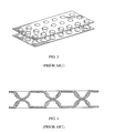
- FIG. 2 is an edge view schematic representation of ballistic resistant article of the invention including a blast mitigating material that is formed from a pair of sheets having a plurality of inwardly facing, opposing protrusions.
- FIG. 3 is a perspective view of the top and bottom sheets of a prior art blast mitigating material incorporating a pair of elastically deformable sheets having a plurality of inwardly facing, opposing, hemispherical elastically deformable protrusions.
- FIG. 4 is a cross-section view of the inwardly facing, opposing, hemispherical elastically deformable protrusions from FIG. 3 .
- FIG. 5 is a perspective view of a prior art blast mitigating material of FIG. 3 having a wall member along the periphery of the sheet surfaces.
- FIG. 6 is an edge view schematic representation of an alternative prior art blast mitigating material.
- FIG. 7 is a graph showing spall resistant liner protection performance in overmatch testing with varied spacing between the spall resistant liner and an object hull.
- FIG. 8 is a graph showing spall resistant liner protection performance in overmatch testing with varied spall resistant liner areal densities.
- FIG. 9 is a cross-section view schematic representation from the prior art of metal armor without a spall resistant liner or blast mitigation material attached thereto being contacted by a high velocity projectile and showing metal spall being discharged therefrom.
- FIG. 10 illustrates the method of measuring 1 ⁇ 2 spall cone angle ⁇ for the Inventive and Comparative Examples.
- spallation describes the material failure and fragmentation of a surface due to a high velocity impact, such as shockwave impact from a detonated IED or the impact of a high velocity projectile, including rocket propelled grenades and other shaped charge threats.
- the spallation of a metal armor surface due to the impact of a high velocity projectile is schematically illustrated in FIG. 9 .
- a projectile contacting an outer surface of metal armor impacts the armor with sufficient force to dislodge fragments from the inner surface of the armor.
- the fragments referred to as spall, are propelled from the inner surface of the armor along a conical path referred to in the art as the spall angle or spall cone angle.
- spall fragments are a threat to harm and significantly injure vehicle occupants.
- the ballistic resistant articles of the invention minimize this threat, reinforcing the vehicle or other object with articles that combine both a blast mitigating material and a spall resistant substrate, also referred to herein as a spall resistant liner.
- a “spall resistant” substrate or liner is a material that will absorb the energy from the spall and either stop it completely or reduce its velocity.
- the spall resistant substrate may be fibrous, being formed from fabrics or other fibrous materials, including fibrous tapes, which includes both non-woven fibrous tapes and woven fibrous tapes, or the spall resistant substrate may be formed from non-fibrous materials, such as non-fibrous tapes.
- the term “tape” refers to a narrow strip of fibrous or non-fibrous material. Tapes are generally flat structures having a substantially rectangular cross-section and having a thickness of about 0.5 mm or less, more preferably about 0.25 mm or less, still more preferably about 0.1 mm or less and still more preferably about 0.05 mm or less.
- the polymeric tapes have a thickness of up to about 3 mils (76.2 ⁇ m), more preferably from about 0.35 mil (8.89 ⁇ m) to about 3 mils (76.2 ⁇ m), and most preferably from about 0.35 mil to about 1.5 mils (38.1 ⁇ m). Thickness is measured at the thickest region of the cross-section.
- a tape generally has a width less than or equal to about 6 inches (15.24 cm), with a preferred width of from about 2.5 mm to about 50 mm, more preferably from about 5 mm to about 50 mm, still more preferably from about 5 mm to about 25.4 mm (1 inch), even more preferably from about 5 mm to about 20 mm, and most preferably from about 5 mm to about 10 mm.
- the polymeric tapes formed herein are most preferably fabricated to have dimensions that achieve an average cross-sectional aspect ratio, i.e. the ratio of the greatest to the smallest dimension of cross-sections averaged over the length of the tape article, of greater than about 3:1, more preferably at least about 5:1, still more preferably at least about 10:1, still more preferably at least about 20:1, still more preferably at least about 50:1, still more preferably at least about 100:1, still more preferably at least about 250:1 and most preferred polymeric tapes have an average cross-sectional aspect ratio of at least about 400:1.
- an average cross-sectional aspect ratio i.e. the ratio of the greatest to the smallest dimension of cross-sections averaged over the length of the tape article, of greater than about 3:1, more preferably at least about 5:1, still more preferably at least about 10:1, still more preferably at least about 20:1, still more preferably at least about 50:1, still more preferably at least about 100:1, still more preferably at least about 250:1 and most preferred
- the ballistic resistant articles 10 are coupled with a surface of an object 16 such that a spall resistant substrate 12 is spaced apart from the surface of the object 16 , wherein a blast mitigating material 14 is positioned contiguous to the object surface.
- a “fiber layer” as used herein may comprise a single-ply of unidirectionally oriented fibers, a plurality of non-consolidated plies of unidirectionally oriented fibers, a plurality of consolidated plies of unidirectionally oriented fibers, a woven fabric, a plurality of consolidated woven fabrics, or any other fabric structure that has been formed from a plurality of fibers, including felts, mats and other structures, such as those comprising randomly oriented fibers.
- a “layer” describes a generally planar arrangement.
- a fiber layer will have both an outer top surface and an outer bottom surface.
- a “single-ply” of unidirectionally oriented fibers comprises an arrangement of substantially non-overlapping fibers that are aligned in a unidirectional, substantially parallel array. This type of fiber arrangement is also known in the art as a “unitape”, “unidirectional tape”, “UD” or “UDT.”
- an “array” describes an orderly arrangement of fibers or yarns, which is exclusive of woven fabrics, and a “parallel array” describes an orderly parallel arrangement of fibers or yarns.
- the term “oriented” as used in the context of “oriented fibers” refers to the alignment of the fibers.
- a woven fabric or felt may comprise a single fiber ply.
- a non-woven fabric formed from unidirectional fibers typically comprises a plurality of fiber plies stacked on each other and consolidated.
- a “single-layer” structure refers to any monolithic fibrous structure composed of one or more individual plies or individual layers that have been merged, i.e. consolidated by low pressure lamination or by high pressure molding, into a single unitary structure, optionally together with a polymeric binder material.
- solidating it is meant that a polymeric binder material together with each fiber ply is combined into a single unitary layer. Consolidation can occur via drying, cooling, heating, pressure or a combination thereof. Heat and/or pressure may not be necessary, as the fibers or fabric layers may just be glued together, as is the case in a wet lamination process.
- composite refers to combinations of fibers or tapes, typically with at least one polymeric binder material.
- a “complex composite” as used herein refers to a consolidated combination of a plurality of fiber layers. As described herein, “non-woven” fabrics include all fabric structures that are not formed by weaving.
- non-woven fabrics may comprise a plurality of unitapes that are at least partially coated with a polymeric binder material, stacked/overlapped and consolidated into a single-layer, monolithic element, as well as a felt or mat comprising non-parallel, randomly oriented fibers that are preferably coated with a polymeric binder composition.
- the spall resistant substrate 12 preferably comprises one or more layers, each layer comprising a plurality of high-strength, high tensile modulus polymeric fibers and/or non-fibrous high-strength, high tensile modulus polymeric tapes.
- a “high-strength, high tensile modulus” fiber or tape is one which has a preferred tenacity of at least about 7 g/denier or more, a preferred tensile modulus of at least about 150 g/denier or more, and preferably an energy-to-break of at least about 8 J/g or more, each as measured by ASTM D2256 for fibers and ASTM D882 (or another suitable method as determined by one skilled in the art) for polymeric tapes.
- the term “denier” refers to the unit of linear density, equal to the mass in grams per 9000 meters of fiber/yarn or tape.
- tenacity refers to the tensile stress expressed as force (grams) per unit linear density (denier) of an unstressed specimen.
- the “initial modulus” of a fiber or tape is the property of a material representative of its resistance to deformation.
- tensile modulus refers to the ratio of the change in tenacity, expressed in grams-force per denier (g/d) to the change in strain, expressed as a fraction of the original fiber or tape length (in/in).
- high tensile modulus fibers include polyolefin fibers, including high density and low density polyethylene.
- polyolefin fibers including high density and low density polyethylene.
- extended chain polyolefin fibers such as highly oriented, high molecular weight polyethylene fibers, particularly ultra-high molecular weight polyethylene fibers, and polypropylene fibers, particularly ultra-high molecular weight polypropylene fibers.
- aramid fibers particularly para-aramid fibers, polyamide fibers, polyethylene terephthalate fibers, polyethylene naphthalate fibers, extended chain polyvinyl alcohol fibers, extended chain polyacrylonitrile fibers, polybenzoxazole (PBO) fibers, polybenzothiazole (PBT) fibers, liquid crystal copolyester fibers, rigid rod fibers such as M5® fibers, and glass fibers, including electric grade fiberglass (E-glass; low alkali borosilicate glass with good electrical properties), structural grade fiberglass (S-glass; a high strength magnesia-alumina-silicate) and resistance grade fiberglass (R-glass; a high strength alumino silicate glass without magnesium oxide or calcium oxide).
- E-glass electric grade fiberglass
- S-glass structural grade fiberglass
- R-glass resistance grade fiberglass
- R-glass a high strength alumino silicate glass without magnesium oxide or calcium oxide
- the most preferred fiber types include polyethylene, particularly extended chain polyethylene fibers, aramid fibers, PBO fibers, liquid crystal copolyester fibers, polypropylene fibers, particularly highly oriented extended chain polypropylene fibers, polyvinyl alcohol fibers, polyacrylonitrile fibers and rigid rod fibers, particularly M5® fibers.
- aramid fibers particularly extended chain polyethylene fibers, aramid fibers, PBO fibers, liquid crystal copolyester fibers, polypropylene fibers, particularly highly oriented extended chain polypropylene fibers, polyvinyl alcohol fibers, polyacrylonitrile fibers and rigid rod fibers, particularly M5® fibers.
- aramid fibers are aramid fibers, polyethylene fibers, polypropylene fibers and glass fibers.
- preferred fibers are extended chain polyethylenes having molecular weights of at least 300,000, preferably at least one million and more preferably between two million and five million.
- extended chain polyethylene (ECPE) fibers may be grown in solution spinning processes such as described in U.S. Pat. Nos. 4,137,394 or 4,356,138, which are incorporated herein by reference, or may be spun from a solution to form a gel structure, such as described in U.S. Pat. Nos.
- Particularly preferred fiber types for use in the spall resistant substrate 12 of the invention are any of the polyethylene fibers sold under the trademark SPECTRA® from Honeywell International Inc. SPECTRA® fibers are well known in the art. Other useful polyethylene fiber types also include and DYNEEMA® UHMWPE yarns commercially available from Royal DSM N.V. Corporation of Heerlen, The Netherlands.
- aramid (aromatic polyamide) or para-aramid fibers are commercially available and are described, for example, in U.S. Pat. No. 3,671,542.
- useful poly(p-phenylene terephthalamide) filaments are produced commercially by DuPont under the trademark of KEVLAR®.
- poly(m-phenylene isophthalamide) fibers produced commercially by DuPont of Wilmington, Del. under the trademark NOMEX® and fibers produced commercially by Teijin Aramid Gmbh of Germany under the trademark TWARON®; aramid fibers produced commercially by Kolon Industries, Inc.
- HERACRON® p-aramid fibers SVMTM and RUSARTM which are produced commercially by Kamensk Volokno JSC of Russia and ARMOSTM p-aramid fibers produced commercially by JSC Chim Volokno of Russia.
- Suitable PBO fibers for the practice of this invention are commercially available and are disclosed for example in U.S. Pat. Nos. 5,286,833, 5,296,185, 5,356,584, 5,534,205 and 6,040,050, each of which is incorporated herein by reference.
- Suitable liquid crystal copolyester fibers for the practice of this invention are commercially available and are disclosed, for example, in U.S. Pat. Nos. 3,975,487; 4,118,372 and 4,161,470, each of which is incorporated herein by reference, and including VECTRAN® liquid crystal copolyester fibers commercially available from Kuraray Co., Ltd. of Tokyo, Japan.
- Suitable polypropylene fibers include highly oriented extended chain polypropylene (ECPP) fibers as described in U.S. Pat. No. 4,413,110, which is incorporated herein by reference.
- ECPP extended chain polypropylene
- PV-OH polyvinyl alcohol
- PV-OH polyvinyl alcohol
- PAN polyacrylonitrile
- M5® fibers are formed from pyridobisimidazole-2,6-diyl(2,5-dihydroxy-p-phenylene) and are manufactured by Magellan Systems International of Richmond, Va. and are described, for example, in U.S. Pat. Nos. 5,674,969, 5,939,553, 5,945,537, and 6,040,478, each of which is incorporated herein by reference.
- Fiberglass spall resistant substrates preferably comprise composites of glass fibers, preferably S-glass fibers, which are impregnated with a thermosetting or thermoplastic polymeric resin, such as a thermosetting epoxy or phenolic resin.
- a thermosetting or thermoplastic polymeric resin such as a thermosetting epoxy or phenolic resin.
- Such materials are well known in the art and are commercially available.
- Preferred examples non-exclusively include spall resistant liners comprising S2-Glass® commercially available from AGY of Aiken, S.C.; spall resistant liners formed from HiPerTexTM E-Glass fibers, commercially available from 3B Fibreglass of Battice, Belgium.
- glass fiber materials comprising R-glass fibers, such as those commercially available under the trademark VETROTEX® from Saint-Gobain of Courbevoie, France.
- combinations of all the above materials all of which are commercially available.
- any spall resistant liner materials within the specifications of Department of Defense specification MIL-DTL 64152B.
- the tape may comprise a strip of woven fabric, or may comprise a plurality of fibers or yarns which may be arranged in a generally unidirectional array of generally parallel fibers.
- the spall resistant substrate 12 is a non-fibrous tape material
- suitable high-strength, high tensile modulus polymeric tape materials are polyolefin tapes.
- Preferred polyolefin tapes include polyethylene tapes, such as those commercially available under the trademark TENSYLON®, which is commercially available from E. I. du Pont de Nemours and Company of Wilmington, Del. See, for example, U.S. Pat. Nos.
- polypropylene tapes such as those commercially available under the trademark TEGRIS® from Milliken & Company of Spartanburg, S.C. See, for example, U.S. Pat. No. 7,300,691 which is incorporated herein by reference.
- Polyolefin tape-based composites that are useful as spall resistant substrates herein are also commercially available, for example under the trademark DYNEEMA® BT10 from Royal DSM N.V. Corporation of Heerlen, The Netherlands and under the trademark ENDUMAX® from Teijin Aramid Gmbh of Germany.
- Polymeric tapes may also be formed by other conventionally known methods, such as extrusion, pultrusion, slit film techniques, etc. For example, a unitape of standard thickness may be cut or slit into tapes having the desired lengths.
- a slitting apparatus is disclosed in U.S. Pat. No. 6,098,510 which teaches an apparatus for slitting a sheet material web as it is wound onto said roll.
- U.S. Pat. No. 6,148,871 Another example of a slitting apparatus is disclosed in U.S. Pat. No. 6,148,871, which teaches an apparatus for slitting a sheet of a polymeric film into a plurality of film strips with a plurality of blades.
- the disclosures of both U.S. Pat. No. 6,098,510 and U.S. Pat. No. 6,148,871 are incorporated herein by reference to the extent consistent herewith.
- Methods for fabricating non-woven, non-fibrous polymeric tapes are described, for example, in U.S. Pat. Nos. 7,300,691; 7,964,266 and 7,964,267, which are incorporated herein by reference.
- multiple layers of tape-based materials may be stacked and consolidated/molded in a similar fashion as the fibrous materials, with or without a polymeric binder material.
- the fibers and tapes may be of any suitable denier.
- fibers may have a denier of from about 50 to about 3000 denier, more preferably from about 200 to 3000 denier, still more preferably from about 650 to about 2000 denier, and most preferably from about 800 to about 1500 denier.
- Tapes may have deniers from about 50 to about 30,000, more preferably from about 200 to 10,000 denier, still more preferably from about 650 to about 2000 denier, and most preferably from about 800 to about 1500 denier. The selection is governed by considerations of ballistic effectiveness and cost. Finer fibers/tapes are more costly to manufacture and to weave, but can produce greater ballistic effectiveness per unit weight.
- a high-strength, high tensile modulus fiber/tape is one which has a preferred tenacity of about 7 g/denier or more, a preferred tensile modulus of about 150 g/denier or more and a preferred energy-to-break of about 8 J/g or more, each as measured by ASTM D2256.
- Preferred fibers have a preferred tenacity of about 15 g/denier or more, more preferably about 20 g/denier or more, still more preferably about 25 g/denier or more, still more preferably about 30 g/denier or more, still more preferably about 40 g/denier or more, still more preferably about 45 g/denier or more, and most preferably about 50 g/denier or more.
- Preferred tapes have a preferred tenacity of about 10 g/denier or more, more preferably about 15 g/denier or more, still more preferably about 17.5 g/denier or more, and most preferably about 20 g/denier or more. Wider tapes will have lower tenacities.
- Preferred fibers/tapes also have a preferred tensile modulus of about 300 g/denier or more, more preferably about 400 g/denier or more, more preferably about 500 g/denier or more, more preferably about 1,000 g/denier or more and most preferably about 1,500 g/denier or more.
- Preferred fibers/tapes also have a preferred energy-to-break of about 15 J/g or more, more preferably about 25 J/g or more, more preferably about 30 J/g or more and most preferably have an energy-to-break of about 40 J/g or more.
- the fibers and/or tapes forming the spall resistant substrate 12 are preferably, but not necessarily, at least partially coated with a polymeric binder material.
- a binder is optional because some materials, such as high modulus polyethylene tapes, do not require a polymeric binder to bind together a plurality of said tapes into a molded layer or molded article.
- Useful spall resistant liners may also be formed from, for example, soft woven tapes or fibrous products that require neither a polymeric/resinous binder material nor molding.
- a “polymeric” binder or matrix material includes resins and rubber. When present, the polymeric binder material either partially or substantially coats the individual fibers/tapes of the spall resistant substrate 12 , preferably substantially coating each of the individual fibers/tapes.
- the polymeric binder material is also commonly known in the art as a “polymeric matrix” material. These terms are conventionally known in the art and describe a material that binds fibers or tapes together either by way of its inherent adhesive characteristics or after being subjected to well known heat and/or pressure conditions.
- Suitable polymeric binder materials include both low modulus, elastomeric materials and high modulus, rigid materials.
- tensile modulus means the modulus of elasticity, which for fibers is measured by ASTM D2256 and by ASTM D638 for a polymeric binder material.
- the tensile properties of polymeric tapes may be measured by ASTM D882 or another suitable method as determined by one skilled in the art.
- the rigidity, impact and ballistic properties of the articles formed from the composites of the invention are affected by the tensile modulus of the polymeric binder polymer coating the fibers/tapes.
- a low or high modulus binder may comprise a variety of polymeric and non-polymeric materials.
- a preferred polymeric binder comprises a low modulus elastomeric material.
- a low modulus elastomeric material has a tensile modulus measured at about 6,000 psi (41.4 MPa) or less according to ASTM D638 testing procedures.
- a low modulus polymer preferably is an elastomer having a tensile modulus of about 4,000 psi (27.6 MPa) or less, more preferably about 2400 psi (16.5 MPa) or less, more preferably 1200 psi (8.23 MPa) or less, and most preferably is about 500 psi (3.45 MPa) or less.
- the glass transition temperature (Tg) of the elastomer is preferably less than about 0° C., more preferably the less than about ⁇ 40° C., and most preferably less than about ⁇ 50° C.
- the elastomer also has a preferred elongation to break of at least about 50%, more preferably at least about 100% and most preferably has an elongation to break of at least about 300%.
- polymeric binder A wide variety of materials and formulations having a low modulus may be utilized as the polymeric binder.
- Representative examples include polybutadiene, polyisoprene, natural rubber, ethylene-propylene copolymers, ethylene-propylene-diene terpolymers, polysulfide polymers, polyurethane elastomers, chlorosulfonated polyethylene, polychloroprene, plasticized polyvinylchloride, butadiene acrylonitrile elastomers, poly(isobutylene-co-isoprene), polyacrylates, polyesters, polyethers, fluoroelastomers, silicone elastomers, copolymers of ethylene, polyamides (useful with some fiber/tape types), acrylonitrile butadiene styrene, polycarbonates, and combinations thereof, as well as other low modulus polymers and copolymers curable below the melting point of the fiber.
- Block copolymers of conjugated dienes and vinyl aromatic monomers are particularly useful.
- Butadiene and isoprene are preferred conjugated diene elastomers.
- Styrene, vinyl toluene and t-butyl styrene are preferred conjugated aromatic monomers.
- Block copolymers incorporating polyisoprene may be hydrogenated to produce thermoplastic elastomers having saturated hydrocarbon elastomer segments.
- A is a block from a polyvinyl aromatic monomer
- B is a block from a conjugated diene elastomer.
- Many of these polymers are produced commercially by Kraton Polymers of Houston, Tex. and described in the bulletin “Kraton Thermoplastic Rubber”, SC-68-81.
- Particularly preferred low modulus polymeric binder polymers comprise styrenic block copolymers sold under the trademark KRATON® commercially produced by Kraton Polymers.
- a particularly preferred polymeric binder material comprises a polystyrene-polyisoprene-polystyrene-block copolymer sold under the trademark KRATON®.
- Preferred high modulus, rigid materials generally have a higher initial tensile modulus than 6,000 psi.
- Preferred high modulus, rigid polymeric binder materials useful herein include polyurethanes (both ether and ester based), epoxies, polyacrylates, phenolic/polyvinyl butyral (PVB) polymers, vinyl ester polymers, styrene-butadiene block copolymers, as well as mixtures of polymers such as vinyl ester and diallyl phthalate or phenol formaldehyde and polyvinyl butyral.
- a particularly preferred rigid polymeric binder material for use in spall resistant substrate 12 is a thermosetting polymer, preferably soluble in carbon-carbon saturated solvents such as methyl ethyl ketone, and possessing a high tensile modulus when cured of at least about 1 ⁇ 10 6 psi (6895 MPa) as measured by ASTM D638.
- Particularly preferred rigid polymeric binder materials are those described in U.S. Pat. No. 6,642,159, the disclosure of which is incorporated herein by reference.
- the polymeric binder may also include fillers such as carbon black or silica, may be extended with oils, or may be vulcanized by sulfur, peroxide, metal oxide or radiation cure systems as is well known in the art.
- polar resins or polar polymer particularly polyurethanes within the range of both soft and rigid materials at a tensile modulus ranging from about 2,000 psi (13.79 MPa) to about 8,000 psi (55.16 MPa).
- Preferred polyurethanes are applied as aqueous polyurethane dispersions that are most preferably co-solvent free. Such includes aqueous anionic polyurethane dispersions, aqueous cationic polyurethane dispersions and aqueous nonionic polyurethane dispersions. Particularly preferred are aqueous anionic polyurethane dispersions, and most preferred are aqueous anionic, aliphatic polyurethane dispersions.
- Such includes aqueous anionic polyester-based polyurethane dispersions; aqueous aliphatic polyester-based polyurethane dispersions; and aqueous anionic, aliphatic polyester-based polyurethane dispersions, all of which are preferably cosolvent free dispersions.
- aqueous anionic polyether polyurethane dispersions aqueous aliphatic polyether-based polyurethane dispersions; and aqueous anionic, aliphatic polyether-based polyurethane dispersions, all of which are preferably cosolvent free dispersions.
- aqueous cationic and aqueous nonionic dispersions are all corresponding variations (polyester-based; aliphatic polyester-based; polyether-based; aliphatic polyether-based, etc.) of aqueous cationic and aqueous nonionic dispersions.
- an aliphatic polyurethane dispersion having a modulus at 100% elongation of about 700 psi or more, with a particularly preferred range of 700 psi to about 3000 psi.
- More preferred are aliphatic polyurethane dispersions having a modulus at 100% elongation of about 1000 psi or more, and still more preferably about 1100 psi or more.
- an aliphatic, polyether-based anionic polyurethane dispersion having a modulus of 1000 psi or more, preferably 1100 psi or more.
- Useful methods include, for example, spraying, extruding or roll coating polymers or polymer solutions onto the fibers/tapes, as well as transporting the fibers/tapes through a molten polymer or polymer solution. Most preferred are methods that substantially coat or encapsulate each of the individual fibers/tapes and cover all or substantially all of the fiber/tape surface area with the polymeric binder material.
- Fibers and tapes that are woven into woven fibrous layers or woven tape layers are preferably at least partially coated with a polymeric binder, followed by a consolidation step similar to that conducted with non-woven layers.
- a consolidation step may be conducted to merge multiple woven fiber or tape layers with each other, or to further merge a binder with the fibers/tapes of said woven layers.
- a plurality of woven fiber layers do not necessarily have to be consolidated, and may be attached by other means, such as with a conventional adhesive, or by stitching, whereas a polymeric binder coating is generally necessary to efficiently consolidate a plurality of non-woven fiber plies.
- Woven fabrics may be formed using techniques that are well known in the art using any fabric weave, such as plain weave, crowfoot weave, basket weave, satin weave, twill weave and the like. Plain weave is most common, where fibers are woven together in an orthogonal 0°/90° orientation. Typically, weaving of fabrics is performed prior to coating the fibers with a polymeric binder, where the woven fabrics are thereby impregnated with the binder. However, the invention is not intended to be limited by the stage at which the polymeric binder is applied. Also useful are 3D weaving methods wherein multi-layer woven structures are fabricated by weaving warp and weft threads both horizontally and vertically. Coating or impregnation with a polymeric binder material is also optional with such 3D woven fabrics, but a binder is specifically not mandatory for the fabrication of a multilayer 3D woven spall resistant substrate 12 .
- non-woven fibrous materials and non-woven tape materials are well known in the art.
- a plurality of fibers are arranged into at least one array, typically being arranged as a fiber web comprising a plurality of fibers aligned in a substantially parallel, unidirectional array.
- fiber bundles are supplied from a creel and led through guides and one or more spreader bars into a collimating comb, followed by coating the fibers with a polymeric binder material.
- a typical fiber bundle will have from about 30 to about 2000 individual fibers.
- the spreader bars and collimating comb disperse and spread out the bundled fibers, reorganizing them side-by-side in a coplanar fashion.
- Ideal fiber spreading results in the individual filaments or individual fibers being positioned next to one another in a single fiber plane, forming a substantially unidirectional, parallel array of fibers without fibers overlapping each other.
- the coated fibers are formed into non-woven fiber layers that comprise a plurality of overlapping, non-woven fiber plies that are consolidated into a single-layer, monolithic element.
- a plurality of stacked, overlapping unitapes are formed wherein the parallel fibers of each single ply (unitape) are positioned orthogonally to the parallel fibers of each adjacent single ply relative to the longitudinal fiber direction of each single ply.
- the stack of overlapping non-woven fiber plies is consolidated under heat and pressure, or by adhering the coatings of individual fiber plies, to form a single-layer, monolithic element which has also been referred to in the art as a single-layer, consolidated network where a “consolidated network” describes a consolidated (merged) combination of fiber plies with the polymeric matrix/binder.
- the spall resistant substrate 12 may also comprise a consolidated hybrid combination of woven fabrics and non-woven fabrics, as well as combinations of non-woven fabrics formed from unidirectional fiber plies and non-woven felt fabrics.
- non-woven fiber layers or fabrics include from 1 to about 6 plies, but may include as many as about 10 to about 20 plies as may be desired for various applications.
- the greater the number of plies translates into greater ballistic resistance, but also greater weight.
- excellent ballistic resistance is achieved when individual fiber plies are cross-plied such that the fiber alignment direction of one ply is rotated at an angle with respect to the fiber alignment direction of another ply.
- the fiber plies are cross-plied orthogonally at 0° and 90° angles, but adjacent plies can be aligned at virtually any angle between about 0° and about 90° with respect to the longitudinal fiber direction of another ply.
- a five ply non-woven structure may have plies oriented at a 0°/45°/90°/45°/0° or at other angles.
- Such rotated unidirectional alignments are described, for example, in U.S. Pat. Nos. 4,457,985; 4,748,064; 4,916,000; 4,403,012; 4,623,574; and 4,737,402, all of which are incorporated herein by reference to the extent not incompatible herewith.
- Consolidation can occur via drying, cooling, heating, pressure or a combination thereof. Heat and/or pressure may not be necessary, as the fibers or fabric layers may just be glued together, as is the case in a wet lamination process.
- consolidation is done by positioning the individual fiber plies on one another under conditions of sufficient heat and pressure to cause the plies to combine into a unitary fabric. Consolidation may be done at temperatures ranging from about 50° C. to about 175° C., preferably from about 105° C.
- Consolidation may also be conducted by vacuum molding the material in a mold that is placed under a vacuum. Vacuum molding technology is well known in the art. Most commonly, a plurality of orthogonal fiber webs are “glued” together with the binder polymer and run through a flat bed laminator to improve the uniformity and strength of the bond. Further, the consolidation and polymer application/bonding steps may comprise two separate steps or a single consolidation/lamination step.
- consolidation may be achieved by molding under heat and pressure in a suitable molding apparatus.
- molding is conducted at a pressure of from about 50 psi (344.7 kPa) to about 5,000 psi (34,470 kPa), more preferably about 100 psi (689.5 kPa) to about 3,000 psi (20,680 kPa), most preferably from about 150 psi (1,034 kPa) to about 1,500 psi (10,340 kPa).
- Molding may alternately be conducted at higher pressures of from about 5,000 psi (34,470 kPa) to about 15,000 psi (103,410 kPa), more preferably from about 750 psi (5,171 kPa) to about 5,000 psi, and more preferably from about 1,000 psi to about 5,000 psi.
- the molding step may take from about 4 seconds to about 45 minutes.
- Preferred molding temperatures range from about 200° F. ( ⁇ 93° C.) to about 350° F. ( ⁇ 177° C.), more preferably at a temperature from about 200° F. to about 300° F. and most preferably at a temperature from about 200° F. to about 280° F.
- the pressure under which the fiber layers are molded has a direct effect on the stiffness or flexibility of the resulting molded product. Particularly, the higher the pressure at which they are molded, the higher the stiffness, and vice-versa.
- the quantity, thickness and composition of the fiber plies and polymeric binder coating type also directly affects the stiffness of the spall resistant substrate 12 .
- molding is a batch process and consolidation is a generally continuous process. Further, molding typically involves the use of a mold, such as a shaped mold or a match-die mold when forming a flat panel, and does not necessarily result in a planar product. Normally consolidation is done in a flat-bed laminator, a calendar nip set or as a wet lamination to produce soft (flexible) body armor fabrics. Molding is typically reserved for the manufacture of hard armor, e.g. rigid plates. In either process, suitable temperatures, pressures and times are generally dependent on the type of polymeric binder coating materials, polymeric binder content, process used and fiber type.
- the total weight of the binder/matrix comprising the spall resistant substrate 12 preferably comprises from about 2% to about 50% by weight, more preferably from about 5% to about 30%, more preferably from about 7% to about 20%, and most preferably from about 11% to about 16% by weight of the fibers plus the weight of the coating.
- a lower binder/matrix content is appropriate for woven fabrics, wherein a polymeric binder content of greater than zero but less than 10% by weight of the fibers plus the weight of the coating is typically most preferred, but this is not intended as limiting.
- phenolic/PVB impregnated woven aramid fabrics are sometimes fabricated with a higher resin content of from about 20% to about 30%, although around 12% content is typically preferred.
- the spall resistant substrate 12 may also optionally comprise one or more thermoplastic polymer layers attached to one or both of the outer surfaces of the spall resistant substrate 12 .
- Suitable polymers for the thermoplastic polymer layer non-exclusively include polyolefins, polyamides, polyesters (particularly polyethylene terephthalate (PET) and PET copolymers), polyurethanes, vinyl polymers, ethylene vinyl alcohol copolymers, ethylene octane copolymers, acrylonitrile copolymers, acrylic polymers, vinyl polymers, polycarbonates, polystyrenes, fluoropolymers and the like, as well as co-polymers and mixtures thereof, including ethylene vinyl acetate (EVA) and ethylene acrylic acid.
- EVA ethylene vinyl acetate
- polyethylene is a polyethylene.
- useful polyethylenes are low density polyethylene (LDPE), linear low density polyethylene (LLDPE), medium density polyethylene (MDPE), linear medium density polyethylene (LMDPE), linear very-low density polyethylene (VLDPE), linear ultra-low density polyethylene (ULDPE), high density polyethylene (HDPE) and co-polymers and mixtures thereof.
- thermoplastic polymer layer may be bonded to the substrate 12 surfaces using well known techniques, such as thermal lamination.
- laminating is done by positioning the individual layers on one another under conditions of sufficient heat and pressure to cause the layers to combine into a unitary structure. Lamination may be conducted at temperatures ranging from about 95° C. to about 175° C., preferably from about 105° C.
- thermoplastic polymer layers may alternatively be bonded to the substrate 12 surfaces with hot glue or hot melt fibers as would be understood by one skilled in the art.
- a spall resistant substrate comprises a plurality of unidirectional fiber plies or tape plies wherein a thermoplastic polymer layers is positioned between each adjacent fiber ply or tape ply.
- the spall resistant substrate has the following structure: thermoplastic polymer film/binder-less 0° UDT/thermoplastic polymer film/90° binder-less UDT thermoplastic polymer film.
- the spall resistant substrate may include additional binder-less UDT plies where a thermoplastic polymer film is present between each pair of adjacent UDT plies.
- a unitape may comprise a plurality of parallel fibers or a plurality of parallel tapes. This exemplary embodiment is not intended to be strictly limiting.
- the UDT elongate bodies i.e.
- the outermost thermoplastic polymer films may also be optionally excluded as determined by one skilled in the art.
- Such binder-less structures may be made by stacking the component layers on top of each other in coextensive fashion and consolidating/molding them together according to the consolidation/molding conditions described herein.
- the thickness of the spall resistant substrate 12 will correspond to the thickness of the individual fibers/tapes and the number of fiber/tape plies or layers incorporated into the spall resistant substrate 12 .
- a preferred woven fabric will have a preferred thickness of from about 25 ⁇ m to about 600 ⁇ m per ply/layer, more preferably from about 50 ⁇ m to about 385 ⁇ m and most preferably from about 75 ⁇ m to about 255 ⁇ m per ply/layer.
- a preferred two-ply non-woven fabric will have a preferred thickness of from about 12 ⁇ m to about 600 ⁇ m, more preferably from about 50 ⁇ m to about 385 ⁇ m and most preferably from about 75 ⁇ m to about 255 ⁇ m.
- thermoplastic polymer layers are preferably very thin, having preferred layer thicknesses of from about 1 ⁇ m to about 250 ⁇ m, more preferably from about 5 ⁇ m to about 25 ⁇ m and most preferably from about 5 ⁇ m to about 9 ⁇ m.
- Discontinuous webs such as SPUNFAB® non-woven webs are preferably applied with a basis weight of 6 grams per square meter (gsm). While such thicknesses are preferred, it is to be understood that other thicknesses may be produced to satisfy a particular need and yet fall within the scope of the present invention.
- the spall resistant substrate 12 comprises multiple fiber/tape plies or layers, which layers are stacked one upon another and optionally, but preferably, consolidated.
- the spall resistant substrate 12 will have a preferred composite areal density of from about 0.2 psf to about 8.0 psf, more preferably from about 0.3 psf to about 6.0 psf, still more preferably from about 0.5 psf to about 5.0 psf, still more preferably from about 0.5 psf to about 3.5 psf, still more preferably from about 1.0 psf to about 3.0 psf, and most preferably from about 1.5 psf to about 2.5 psf.
- the ballistic resistant article 10 exhibits improved ballistic resistance.
- consistent levels of ballistic performance may be achieved with a spall resistant substrate 12 having a lower areal density than liners of the related art, thereby reducing the weight of the reinforcing armor.
- spall resistant substrate 12 of the ballistic resistant articles 10 may comprise any conventionally known and commercially available spall resistant liner material, such as the HiPerTexTM and S2-Glass® fiberglass based spall resistant liners mentioned previously herein, as well as any commercially available KEVLAR® reinforced plastic (KRP) spall resistant liner.
- KRP KEVLAR® reinforced plastic
- the blast mitigating material 14 may be formed from any suitable flexible material that is most preferably an elastically deformable, shock absorbing material, including commercially available blast mitigating materials that would be known to one skilled in the art.
- an “elastically deformable” material is a material, typically a polymeric material, that is capable of elastic deformation, wherein “elastic deformation” is a temporary and reversible deformation rather than a permanent deformation, such that when forces causing deformation are no longer applied, the material (or object) returns to its original, non-deformed shape.
- elastically deformable, shock absorbing materials commercially available from Skydex Technologies, Inc. of Englewood, Colo.
- FIG. 3 , FIG. 4 and FIG. 5 each illustrate cushioning materials as described and illustrated in U.S. Pat. No. 6,029,962.
- FIG. 6 illustrates an alternative useful cushioning material as described and illustrated in U.S. Pat. No. 7,574,760.
- the blast mitigating material 14 preferably comprises a pair of sheets comprising first and second surfaces with a plurality of integrally formed, inwardly extending indentations protruding from the first and second surfaces.
- the pair of elastically deformable sheets is spaced from each other to define a cavity therebetween, each sheet having a plurality of inwardly facing, opposing, elastically deformable protrusions extending into the cavity, such that the elastically deformable protrusions extend between the first and second surfaces.
- the protrusions are hemispherical, but they may have alternative shapes, such as illustrated in FIG. 6 and as described in U.S.
- the protrusions are preferably hollow, but may alternatively be solid nodules or may be filled with a material, such as foam, a polymeric material such as rubber, or a particulate material, such as rubber particles.
- the surfaces may optionally be formed of mesh material to allow the passage of gas or fluid therethrough, and one or more inserts may be placed in the protrusions.
- the blast mitigation material 14 may be constructed by molding upper and lower elastically deformable sheets wherein the molds are configured to provide indentations in the top and bottom surfaces. The upper and lower sheets are then joined to complete the blast mitigating material 14 . The point of contact can be fixed or non-fixed.
- the blast mitigating material 14 may also include a wall member coextensive with the top and bottom surfaces, as shown in FIG. 5 .
- the blast mitigating material 14 may also comprise at least one additional elastically deformable sheet comprising a plurality of integrally formed elastically deformable protrusions, where said at least one additional sheet is adhered or otherwise attached to at least one surface of said pair of spaced apart elastically deformable sheets. Means for the fabrication of these preferred commercially available blast mitigation materials are described in detail in the Skydex Technologies, Inc. patents which are incorporated herein by reference.
- the blast mitigation material 14 is preferably formed from a flexible high polymer thermoplastic resin, including both crystalline and amorphous thermoplastic polymers.
- thermoplastic polymers non-exclusively include acrylonitrile-butadiene-styrene copolymers, styrene, cellulosic polymers, polycarbonates, nylons, polyethylene, polypropylene and polyurethane.
- Particularly preferred thermoplastic polymers for use in the blast mitigating material 14 of the present invention are thermoplastic polyurethanes, nylons, polyesters, polyethylenes, polyamides and combinations thereof.
- blast mitigation material 14 is not limited to the commercially available constructions available from Skydex Technologies, Inc. and may comprise other suitable constructions as would be determined by one skilled in the art wherein the blast mitigation material 14 is capable of being attached to a spall resistant substrate 12 .
- blast mitigating material 14 may comprise flexible, elastically deformable polymeric particulates or foams, elastically deformable balloons, elastically deformable micro-balloons, elastically deformable bladders, elastically deformable hollow spheres, as well as combinations of these materials and sheets formed from said materials.
- the blast mitigating material may also comprise alternative hollow structures formed from an elastically deformable polymeric material.
- blast mitigating material comprises a material that is elastically deformable. It is also most preferred that such an elastically deformable blast mitigating material be at least partially hollow such that at least a portion of the volume between the spall resistant substrate 12 and a reinforced object 16 is occupied by air.
- the outermost area of the protrusions constitute a surface to which the spall resistant substrate 12 may be coupled with or attached.
- the blast mitigating material 14 comprises a single sheet of the SKYDEX® material or three sheets of the SKYDEX® material rather than a pair of sheets of said SKYDEX® material
- the spall resistant substrate 12 may be coupled with or attached to either side of the sheet, and the outermost area of the protrusions constituting a surface (or surfaces) that is suitable for contact with and attachment with the spall resistant substrate 12 .
- the thickness of the blast mitigating material 14 may vary as would be determined by one skilled in the art in view of the spatial limitations of the object to be reinforced with the ballistic resistant articles 10 .
- the blast mitigating material 14 has a thickness of at least about 1-inch (2.54 cm), more preferably at least about 2-inches (5.08 cm).
- the blast mitigating material 14 is a commercially procured SKYDEX® material
- the thickness of the material 14 will depend on the number of sheets of SKYDEX® material incorporated. While such thicknesses are preferred, it is to be understood that other thicknesses may be produced to satisfy a particular need and yet fall within the scope of the present invention.
- the spall resistant substrate 12 and the blast mitigating material 14 may be coupled with each other without attaching them to each other, or they may be attached to each other using any suitable means in the art.
- the spall resistant substrate 12 and the blast mitigating material 14 are preferably attached to each other with an adhesive. Any suitable adhesive material may be used.
- Suitable adhesives non-exclusively include elastomeric materials such as polyethylene, cross-linked polyethylene, chlorosulfonated polyethylene, ethylene copolymers, polypropylene, propylene copolymers, polybutadiene, polyisoprene, natural rubber, ethylene-propylene copolymers, ethylene-propylene-diene terpolymers, polysulfide polymers, polyurethane elastomers, polychloroprene, plasticized polyvinylchloride using one or more plasticizers that are well known in the art (such as dioctyl phthalate), butadiene acrylonitrile elastomers, poly(isobutylene-co-isoprene), polyacrylates, polyesters, unsaturated polyesters, polyethers, fluoroelastomers, silicone elastomers, copolymers of ethylene, thermoplastic elastomers, phenolics, polybutyrals, epoxy polymers,
- Particularly preferred adhesives include methacrylate adhesives, cyanoacrylate adhesives, UV cure adhesives, urethane adhesives, epoxy adhesives and blends of the above materials.
- an adhesive comprising a polyurethane thermoplastic adhesive, particularly a blend of one or more polyurethane thermoplastics with one or more other thermoplastic polymers, is preferred.
- the adhesive comprises polyether aliphatic polyurethane.
- Such adhesives may be applied, for example, in the form of a hot melt, film, paste or spray, or as a two-component liquid adhesive.
- suitable means for attachment non-exclusively include stitching them together, bolting or screwing them together, as well as attachment with hook-and-loop fasteners such as VELCRO® brand products commercially available from Velcro Industries B.V. of Curacao, The Netherlands, or 3MTM brand hook and loop fasteners, and the like.
- the blast mitigating material 14 may be coupled with only one spall resistant substrate 12 , said substrate 12 being coupled with only one of said first and second surfaces of the blast mitigating material 14 , or it may be coupled with more than one spall resistant substrate 12 on one or both of its surfaces.
- the articles 10 may also comprise more than one blast mitigating material 14 attached to one or both outer surfaces of the spall resistant substrate 12 . To minimize the weight of the ballistic resistant article, it is most preferred that only one spall resistant substrate 12 is coupled with only one of said first and second surfaces of the blast mitigating material 14 .
- a protective cover 18 is positioned on or attached to an outer surface of the spall resistant substrate 12 .
- Suitable protective covers 18 include, for example, fabric materials such upholstery fabrics, as well as polymeric surface covers, such as molded rubber or non-molded rubber sheets.
- An example of a suitable upholstery fabric useful as a protective cover 18 is CORDURA® brand fabric or covers fabricated from CORDURA® brand nylon fibers, each of which are commercially available from Invista S.à r.l. of Wichita, Kans.
- the ballistic resistant articles of the invention are suitable for reinforcing or armoring any type of object as may be desired by one skilled in the art, but are particularly useful for reinforcing vehicles such as automobiles, military tanks, aircraft and marine vessels.
- a space between a spall resistant liner and a vehicle hull can increase spall resistant liner performance, and it has been unexpectedly found that when the spall resistant substrate 12 is coupled with a blast mitigating material 14 , particularly an elastically deformable blast mitigating material, thereby spacing the substrate 12 from a surface of a reinforced object 16 , the ballistic resistant article 10 exhibits improved ballistic resistance.
- objects are to be reinforced are reinforced with the ballistic resistant articles 10 of the invention by positioning the articles 10 such that the blast mitigating material 14 is contiguous to the object 16 , such that at least a portion of the volume between the object and the spall resistant substrate is occupied by air.
- Articles 10 may be attached to the object to be reinforced or may be loosely placed into a desired position without being attached or otherwise secured to the object.
- articles 10 may be bolted into the hull of a vehicle, adhered to the hull of the vehicle, or otherwise attached by another means that would be readily determined by one skilled in the art. Suitable adhesives include those previously described herein.
- a spall resistant liner with and without a blast mitigating material attached to one of its surfaces.
- a strike face of high hard steel (15 mm of ARMOX® 440T steel commercially available from SSAB Technology AB of Sweden) was used as representative of a vehicle hull.
- the spall resistant liner was constructed from the same material, comprising 19 consolidated layers of a 4-ply, non-woven aramid-fiber based composite fabric identified herein as GV-2018.
- THE GV-2018 composite included a polyurethane binder material with a total binder content of 13% by weight of the layer.
- the spall resistant liner had an areal density of 2.0 lb/ft 2 (psf).
- Example 1 the spall resistant liner tested was placed directly behind the strike face hull and clamped in place.
- Example 2 the spall resistant liner tested was spaced apart from the strike face hull by 13.5 mm.
- Example 3 the spall resistant liner tested was spaced apart from the strike face hull by 30 mm.
- the spall resistant liner was adhered to one article of SKYDEX® blast mitigating material, where the SKYDEX® material comprised a pair of sheets comprising hemispherical-shaped protrusions as described in U.S. Pat. No. 6,029,962.
- Example 5 the spall resistant liner was adhered to two articles of SKYDEX® blast mitigating material, where the SKYDEX® material comprised a pair of sheets comprising hemispherical-shaped protrusions as described in U.S. Pat. No. 6,029,962.
- the SKYDEX® material was positioned between the spall resistant liner and the strike face hull, and the thickness of each sheet of the SKYDEX® material was approximately 30 mm.
- Testing was conducted using an RPG-7 stimulant as the ballistic threat.
- a witness plate was placed behind the samples and the perforations in the witness plate were collected and measured to determine the 1 ⁇ 2 spall cone angle ( ⁇ ).
- FIG. 10 illustrates how angle ⁇ was measured.
- the 1 ⁇ 2 spall cone angle ⁇ was then used to compare the cone angle reduction in degrees relative to the 1 ⁇ 2 spall cone angle ⁇ on a baseline metal with no spall resistant liner. For each test shot, four angles were calculated based on percentages (100%, 99%, 95% and 90%) of the total number of perforations in the witness plate. The results are summarized in Table 1 and are graphically illustrated in FIG. 7 .
- Examples 1-5 illustrate that spall resistant liner performance was improved when spaced from the ARMOX® hull, but the performance of the system was significantly better when the SKYDEX® material was in the gap space.
- Example 6 the testing described for Comparative Example 1 was repeated where the test was performed with the spall resistant liner placed directly behind the strike face hull and clamped in place, but in these Examples the performance of spall resistant liners having varying areal densities were compared.
- Example 6 (Comparative) and Example 7 (Comparative) are duplicates of Example 1 (Comparative), testing a spall resistant liner having an areal density of 2.0 psf.
- the spall resistant liner had an areal density of 3.5 psf.
- the spall resistant liner had an areal density of 5.0 psf.
- Inventive Example 12 is a duplicate of Inventive Example 4, where a 2.0 psf spall resistant liner was adhered to one article of SKYDEX® blast mitigating material having a thickness of approximately 30 mm.
- the spall resistant liner was constructed from the same materials and comprised GV-2018 as per Examples 1-5. The results are summarized in Table 2 and are graphically illustrated in FIG. 8 .
Landscapes
- Engineering & Computer Science (AREA)
- General Engineering & Computer Science (AREA)
- Ceramic Engineering (AREA)
- Aiming, Guidance, Guns With A Light Source, Armor, Camouflage, And Targets (AREA)
- Laminated Bodies (AREA)
- Moulding By Coating Moulds (AREA)
- Body Structure For Vehicles (AREA)
Abstract
Spall suppressing ballistic resistant vehicular armor. More particularly, a lightweight spall suppressing ballistic resistant vehicular armor system incorporating both a spall resistant liner and a blast mitigating material. The blast mitigating material is positioned contiguous to a vehicle hull to thereby space the spall resistant liner from the vehicle hull, thereby improving the performance of the liner and the overall system.
Description
- This application claims the benefit of co-pending U.S. Provisional Application Ser. No. 61/618,107, filed on Mar. 30, 2012, the disclosure of which is incorporated by reference herein in its entirety.
- 1. Technical Field
- The invention relates to spall suppressing ballistic resistant vehicular armor. More particularly, the invention pertains to a lightweight spall suppressing ballistic resistant vehicular armor system incorporating anti-spall and blast mitigating elements.
- 2. Description of the Related Art
- Vehicles intended for use in combat environments are often armored to protect the vehicle occupants from ballistic threats. Harm to vehicle occupants from ballistic threats may occur, for example, from the penetration of ballistic rounds or other such projectiles through the vehicle hull and into the vehicle interior, and/or as a result of the impact of high pressure blast energy from improvised explosive devices (IEDs). Equipping vehicles with armor reduces the likelihood that ballistic threats will breach the hull and penetrate the vehicle, while coupling armor with blast mitigating materials helps suppress shock waves and reduce the impact of high pressure blast energy. Blast mitigating materials also help to contain exploding fragments from IEDs as well as fragments from fractured projectiles.
- It is also recognized that high velocity fragments of metal released from the inside surface of a vehicle hull due to a high velocity impact with the vehicle, also known as spall, is a primary cause of vehicular casualties in combat. To control such metal spall that may occur when a threat impacts or penetrates the hull of a vehicle, a spall resistant liner is typically used directly behind the vehicle hull material, serving as a barrier to incoming projectile fragments or debris. For example, U.S. Pat. No. 4,664,967 discloses a ballistic spall resistant liner for military vehicles where the liner has multiple and repeating layers made of high tensile strength fabric and steel. U.S. Pat. No. 4,739,690 discloses ballistic resistant armor with a spall resistant liner containing an outer layer of a plasticized resin. This disclosure does not specify vehicular use of the spall resistant liner.
- It is also known that incorporating a space between a spall resistant liner and a vehicle hull can increase spall resistant liner performance. For example, U.S. Pat. No. 4,934,245 states that spall resistant liners should optimally be spaced from the inner wall of a vehicle by 4 to 17 inches to maximize their effectiveness, noting however that such a construction is unrealistic due to limited useable space within most vehicles. To overcome these spatial limitations, U.S. Pat. No. 4,934,245 teaches attaching an armor plate backed with a spall resistant liner directly to a vehicle hull. U.S. Pat. No. 6,622,608 teaches that armor mass efficiency of vehicle armor can be enhanced by incorporating a standoff plate separated from the base armor material. The standoff plate creates a distance of separation from the base armor in which shell fragments can be turned, shattered, and caught. See also U.S. Pat. No. 6,912,944 which teaches ceramic armor systems with a front spall layer bonded to a front surface of a ceramic plate and a shock absorbing layer bonded to a rear surface of the ceramic plate. This assembly may be bolted into the hull of a vehicle, preferably with an air gap between the shock-absorbing layer and the hull of the vehicle.
- Although it is desirable to equip armored vehicles with both a blast mitigating material and a spall resistant liner, space limitations within the vehicle are restrictive, resulting in no space available to separate the spall resistant liner from the hull. Therefore, there is a need in the art for an improved vehicle armor construction that permits the use of both a blast mitigating material and a spall resistant liner within a vehicle, while also allowing the spall resistant liner to be beneficially spaced from the vehicle hull. This disclosure provides a solution to this need in the art.
- Provided is a ballistic resistant article comprising:
- a) an elastically deformable blast mitigating material having first and second surfaces; and
- b) a spall resistant substrate coupled with at least one of said first and second surfaces of said blast mitigating material, said spall resistant substrate comprising fibers and/or tapes having a tenacity of about 7 g/denier or more and a tensile modulus of about 150 g/denier or more.
- Also provided is a reinforced object which comprises an object coupled with a ballistic resistant article, the ballistic resistant article comprising:
- a) an elastically deformable blast mitigating material having first and second surfaces;
- b) a spall resistant substrate coupled with at least one of said first and second surfaces of said blast mitigating material, said spall resistant substrate comprising fibers and/or tapes having a tenacity of about 7 g/denier or more and a tensile modulus of about 150 g/denier or more; and optionally
- c) a protective cover on an outer surface of the spall resistant substrate;
- wherein the blast mitigating material is contiguous to the object.
- Further provided is a method of forming a ballistic resistant article which comprises:
- a) providing an elastically deformable blast mitigating material having first and second surfaces;
- b) adjoining at least one of said first and second surfaces of the blast mitigating material with at least one spall resistant substrate, said spall resistant substrate comprising fibers and/or tapes having a tenacity of about 7 g/denier or more and a tensile modulus of about 150 g/denier or more; and
- c) optionally covering an outer surface of the at least one spall resistant substrate with a protective cover.
-
FIG. 1 is an edge view schematic representation of ballistic resistant article of the invention including a blast mitigating material positioned between a spall resistant liner and a surface of a reinforced object with a protective cover on the spall resistant liner, where the blast mitigating material comprises a plurality of protrusions. -
FIG. 2 is an edge view schematic representation of ballistic resistant article of the invention including a blast mitigating material that is formed from a pair of sheets having a plurality of inwardly facing, opposing protrusions. -
FIG. 3 is a perspective view of the top and bottom sheets of a prior art blast mitigating material incorporating a pair of elastically deformable sheets having a plurality of inwardly facing, opposing, hemispherical elastically deformable protrusions. -
FIG. 4 is a cross-section view of the inwardly facing, opposing, hemispherical elastically deformable protrusions fromFIG. 3 . -
FIG. 5 is a perspective view of a prior art blast mitigating material ofFIG. 3 having a wall member along the periphery of the sheet surfaces. -
FIG. 6 is an edge view schematic representation of an alternative prior art blast mitigating material. -
FIG. 7 is a graph showing spall resistant liner protection performance in overmatch testing with varied spacing between the spall resistant liner and an object hull. -
FIG. 8 is a graph showing spall resistant liner protection performance in overmatch testing with varied spall resistant liner areal densities. -
FIG. 9 is a cross-section view schematic representation from the prior art of metal armor without a spall resistant liner or blast mitigation material attached thereto being contacted by a high velocity projectile and showing metal spall being discharged therefrom. -
FIG. 10 illustrates the method of measuring ½ spall cone angle α for the Inventive and Comparative Examples. - In the context of the present invention, spallation (or spalling) describes the material failure and fragmentation of a surface due to a high velocity impact, such as shockwave impact from a detonated IED or the impact of a high velocity projectile, including rocket propelled grenades and other shaped charge threats. The spallation of a metal armor surface due to the impact of a high velocity projectile is schematically illustrated in
FIG. 9 . As shown in this prior art figure, a projectile contacting an outer surface of metal armor impacts the armor with sufficient force to dislodge fragments from the inner surface of the armor. The fragments, referred to as spall, are propelled from the inner surface of the armor along a conical path referred to in the art as the spall angle or spall cone angle. When the armor impacted is a vehicle hull, such spall fragments are a threat to harm and significantly injure vehicle occupants. The ballistic resistant articles of the invention minimize this threat, reinforcing the vehicle or other object with articles that combine both a blast mitigating material and a spall resistant substrate, also referred to herein as a spall resistant liner. As used herein, a “spall resistant” substrate or liner is a material that will absorb the energy from the spall and either stop it completely or reduce its velocity. The spall resistant substrate may be fibrous, being formed from fabrics or other fibrous materials, including fibrous tapes, which includes both non-woven fibrous tapes and woven fibrous tapes, or the spall resistant substrate may be formed from non-fibrous materials, such as non-fibrous tapes. As used herein, the term “tape” refers to a narrow strip of fibrous or non-fibrous material. Tapes are generally flat structures having a substantially rectangular cross-section and having a thickness of about 0.5 mm or less, more preferably about 0.25 mm or less, still more preferably about 0.1 mm or less and still more preferably about 0.05 mm or less. In the most preferred embodiments, the polymeric tapes have a thickness of up to about 3 mils (76.2 μm), more preferably from about 0.35 mil (8.89 μm) to about 3 mils (76.2 μm), and most preferably from about 0.35 mil to about 1.5 mils (38.1 μm). Thickness is measured at the thickest region of the cross-section. A tape generally has a width less than or equal to about 6 inches (15.24 cm), with a preferred width of from about 2.5 mm to about 50 mm, more preferably from about 5 mm to about 50 mm, still more preferably from about 5 mm to about 25.4 mm (1 inch), even more preferably from about 5 mm to about 20 mm, and most preferably from about 5 mm to about 10 mm. These dimensions may vary but the polymeric tapes formed herein are most preferably fabricated to have dimensions that achieve an average cross-sectional aspect ratio, i.e. the ratio of the greatest to the smallest dimension of cross-sections averaged over the length of the tape article, of greater than about 3:1, more preferably at least about 5:1, still more preferably at least about 10:1, still more preferably at least about 20:1, still more preferably at least about 50:1, still more preferably at least about 100:1, still more preferably at least about 250:1 and most preferred polymeric tapes have an average cross-sectional aspect ratio of at least about 400:1. - As illustrated in
FIG. 1 andFIG. 2 , the ballisticresistant articles 10 are coupled with a surface of anobject 16 such that a spallresistant substrate 12 is spaced apart from the surface of theobject 16, wherein ablast mitigating material 14 is positioned contiguous to the object surface. - For the purposes of the invention, ballistic resistant articles describe those which exhibit excellent properties against the penetration of deformable projectiles, such as bullets, and against penetration of fragments, such as shrapnel and spall. A “fiber layer” as used herein may comprise a single-ply of unidirectionally oriented fibers, a plurality of non-consolidated plies of unidirectionally oriented fibers, a plurality of consolidated plies of unidirectionally oriented fibers, a woven fabric, a plurality of consolidated woven fabrics, or any other fabric structure that has been formed from a plurality of fibers, including felts, mats and other structures, such as those comprising randomly oriented fibers. A “layer” describes a generally planar arrangement. A fiber layer will have both an outer top surface and an outer bottom surface. A “single-ply” of unidirectionally oriented fibers comprises an arrangement of substantially non-overlapping fibers that are aligned in a unidirectional, substantially parallel array. This type of fiber arrangement is also known in the art as a “unitape”, “unidirectional tape”, “UD” or “UDT.” As used herein, an “array” describes an orderly arrangement of fibers or yarns, which is exclusive of woven fabrics, and a “parallel array” describes an orderly parallel arrangement of fibers or yarns. The term “oriented” as used in the context of “oriented fibers” refers to the alignment of the fibers. The term “fabric” describes structures that may include one or more fiber plies, with or without molding or consolidation of the plies. For example, a woven fabric or felt may comprise a single fiber ply. A non-woven fabric formed from unidirectional fibers typically comprises a plurality of fiber plies stacked on each other and consolidated. When used herein, a “single-layer” structure refers to any monolithic fibrous structure composed of one or more individual plies or individual layers that have been merged, i.e. consolidated by low pressure lamination or by high pressure molding, into a single unitary structure, optionally together with a polymeric binder material. By “consolidating” it is meant that a polymeric binder material together with each fiber ply is combined into a single unitary layer. Consolidation can occur via drying, cooling, heating, pressure or a combination thereof. Heat and/or pressure may not be necessary, as the fibers or fabric layers may just be glued together, as is the case in a wet lamination process. The term “composite” refers to combinations of fibers or tapes, typically with at least one polymeric binder material. A “complex composite” as used herein refers to a consolidated combination of a plurality of fiber layers. As described herein, “non-woven” fabrics include all fabric structures that are not formed by weaving. For example, non-woven fabrics may comprise a plurality of unitapes that are at least partially coated with a polymeric binder material, stacked/overlapped and consolidated into a single-layer, monolithic element, as well as a felt or mat comprising non-parallel, randomly oriented fibers that are preferably coated with a polymeric binder composition.
- The spall
resistant substrate 12 preferably comprises one or more layers, each layer comprising a plurality of high-strength, high tensile modulus polymeric fibers and/or non-fibrous high-strength, high tensile modulus polymeric tapes. As used herein, a “high-strength, high tensile modulus” fiber or tape is one which has a preferred tenacity of at least about 7 g/denier or more, a preferred tensile modulus of at least about 150 g/denier or more, and preferably an energy-to-break of at least about 8 J/g or more, each as measured by ASTM D2256 for fibers and ASTM D882 (or another suitable method as determined by one skilled in the art) for polymeric tapes. As used herein, the term “denier” refers to the unit of linear density, equal to the mass in grams per 9000 meters of fiber/yarn or tape. As used herein, the term “tenacity” refers to the tensile stress expressed as force (grams) per unit linear density (denier) of an unstressed specimen. The “initial modulus” of a fiber or tape is the property of a material representative of its resistance to deformation. The term “tensile modulus” refers to the ratio of the change in tenacity, expressed in grams-force per denier (g/d) to the change in strain, expressed as a fraction of the original fiber or tape length (in/in). - In embodiments where the spall
resistant substrate 12 is a fibrous material, particularly suitable high-strength, high tensile modulus fibers include polyolefin fibers, including high density and low density polyethylene. Particularly preferred are extended chain polyolefin fibers, such as highly oriented, high molecular weight polyethylene fibers, particularly ultra-high molecular weight polyethylene fibers, and polypropylene fibers, particularly ultra-high molecular weight polypropylene fibers. Also suitable are aramid fibers, particularly para-aramid fibers, polyamide fibers, polyethylene terephthalate fibers, polyethylene naphthalate fibers, extended chain polyvinyl alcohol fibers, extended chain polyacrylonitrile fibers, polybenzoxazole (PBO) fibers, polybenzothiazole (PBT) fibers, liquid crystal copolyester fibers, rigid rod fibers such as M5® fibers, and glass fibers, including electric grade fiberglass (E-glass; low alkali borosilicate glass with good electrical properties), structural grade fiberglass (S-glass; a high strength magnesia-alumina-silicate) and resistance grade fiberglass (R-glass; a high strength alumino silicate glass without magnesium oxide or calcium oxide). Each of these fiber types is conventionally known in the art. Also suitable for producing polymeric fibers are copolymers, block polymers and blends of the above materials. - The most preferred fiber types include polyethylene, particularly extended chain polyethylene fibers, aramid fibers, PBO fibers, liquid crystal copolyester fibers, polypropylene fibers, particularly highly oriented extended chain polypropylene fibers, polyvinyl alcohol fibers, polyacrylonitrile fibers and rigid rod fibers, particularly M5® fibers. Specifically most preferred fibers for use in the fabrication of spall
resistant liner 12 are aramid fibers, polyethylene fibers, polypropylene fibers and glass fibers. - In the case of polyethylene, preferred fibers are extended chain polyethylenes having molecular weights of at least 300,000, preferably at least one million and more preferably between two million and five million. Such extended chain polyethylene (ECPE) fibers may be grown in solution spinning processes such as described in U.S. Pat. Nos. 4,137,394 or 4,356,138, which are incorporated herein by reference, or may be spun from a solution to form a gel structure, such as described in U.S. Pat. Nos. 4,413,110; 4,536,536; 4,551,296; 4,663,101; 5,006,390; 5,032,338; 5,578,374; 5,736,244; 5,741,451; 5,958,582; 5,972,498; 6,448,359; 6,746,975; 6,969,553; 7,078,099; 7,344,668 and U.S. patent application publication 2007/0231572, all of which are incorporated herein by reference. Particularly preferred fiber types for use in the spall
resistant substrate 12 of the invention are any of the polyethylene fibers sold under the trademark SPECTRA® from Honeywell International Inc. SPECTRA® fibers are well known in the art. Other useful polyethylene fiber types also include and DYNEEMA® UHMWPE yarns commercially available from Royal DSM N.V. Corporation of Heerlen, The Netherlands. - Preferred are aramid (aromatic polyamide) or para-aramid fibers are commercially available and are described, for example, in U.S. Pat. No. 3,671,542. For example, useful poly(p-phenylene terephthalamide) filaments are produced commercially by DuPont under the trademark of KEVLAR®. Also useful in the practice of this invention are poly(m-phenylene isophthalamide) fibers produced commercially by DuPont of Wilmington, Del. under the trademark NOMEX® and fibers produced commercially by Teijin Aramid Gmbh of Germany under the trademark TWARON®; aramid fibers produced commercially by Kolon Industries, Inc. of Korea under the trademark HERACRON®; p-aramid fibers SVM™ and RUSAR™ which are produced commercially by Kamensk Volokno JSC of Russia and ARMOS™ p-aramid fibers produced commercially by JSC Chim Volokno of Russia.
- Suitable PBO fibers for the practice of this invention are commercially available and are disclosed for example in U.S. Pat. Nos. 5,286,833, 5,296,185, 5,356,584, 5,534,205 and 6,040,050, each of which is incorporated herein by reference. Suitable liquid crystal copolyester fibers for the practice of this invention are commercially available and are disclosed, for example, in U.S. Pat. Nos. 3,975,487; 4,118,372 and 4,161,470, each of which is incorporated herein by reference, and including VECTRAN® liquid crystal copolyester fibers commercially available from Kuraray Co., Ltd. of Tokyo, Japan. Suitable polypropylene fibers include highly oriented extended chain polypropylene (ECPP) fibers as described in U.S. Pat. No. 4,413,110, which is incorporated herein by reference. Suitable polyvinyl alcohol (PV-OH) fibers are described, for example, in U.S. Pat. Nos. 4,440,711 and 4,599,267 which are incorporated herein by reference. Suitable polyacrylonitrile (PAN) fibers are disclosed, for example, in U.S. Pat. No. 4,535,027, which is incorporated herein by reference. Each of these fiber types is conventionally known and is widely commercially available.
- M5® fibers are formed from pyridobisimidazole-2,6-diyl(2,5-dihydroxy-p-phenylene) and are manufactured by Magellan Systems International of Richmond, Va. and are described, for example, in U.S. Pat. Nos. 5,674,969, 5,939,553, 5,945,537, and 6,040,478, each of which is incorporated herein by reference.
- Fiberglass spall resistant substrates preferably comprise composites of glass fibers, preferably S-glass fibers, which are impregnated with a thermosetting or thermoplastic polymeric resin, such as a thermosetting epoxy or phenolic resin. Such materials are well known in the art and are commercially available. Preferred examples non-exclusively include spall resistant liners comprising S2-Glass® commercially available from AGY of Aiken, S.C.; spall resistant liners formed from HiPerTex™ E-Glass fibers, commercially available from 3B Fibreglass of Battice, Belgium. Also suitable are glass fiber materials comprising R-glass fibers, such as those commercially available under the trademark VETROTEX® from Saint-Gobain of Courbevoie, France. Also suitable are combinations of all the above materials, all of which are commercially available. Also suitable are any spall resistant liner materials within the specifications of Department of Defense specification MIL-DTL 64152B.
- In embodiments where the spall
resistant substrate 12 is a fibrous tape, the tape may comprise a strip of woven fabric, or may comprise a plurality of fibers or yarns which may be arranged in a generally unidirectional array of generally parallel fibers. In embodiments where the spallresistant substrate 12 is a non-fibrous tape material, particularly suitable high-strength, high tensile modulus polymeric tape materials are polyolefin tapes. Preferred polyolefin tapes include polyethylene tapes, such as those commercially available under the trademark TENSYLON®, which is commercially available from E. I. du Pont de Nemours and Company of Wilmington, Del. See, for example, U.S. Pat. Nos. 5,091,133; 7,964,266 and 7,964,267 which are incorporated herein by reference. Also suitable are polypropylene tapes, such as those commercially available under the trademark TEGRIS® from Milliken & Company of Spartanburg, S.C. See, for example, U.S. Pat. No. 7,300,691 which is incorporated herein by reference. Polyolefin tape-based composites that are useful as spall resistant substrates herein are also commercially available, for example under the trademark DYNEEMA® BT10 from Royal DSM N.V. Corporation of Heerlen, The Netherlands and under the trademark ENDUMAX® from Teijin Aramid Gmbh of Germany. - Methods for fabricating fibrous tapes are described, for example, in U.S. Pat. No. 8,236,119 and U.S. patent application Ser. Nos. 13/021,262; 13/494,641; 13/568,097; 13/647,926 and 13/708,360, the disclosures of which are incorporated herein by reference. Other methods for fabricating fibrous tapes are described, for example, in U.S. Pat. Nos. 2,035,138; 4,124,420; 5,115,839, or by use of a ribbon loom specialized for weaving narrow woven fabrics or ribbons. Useful ribbon looms are disclosed, for example, in U.S. Pat. Nos. 4,541,461; 5,564,477; 7,451,787 and 7,857,012, each of which is assigned to Textilma AG of Stansstad, Switzerland, and each of which is incorporated herein by reference to the extent consistent herewith, although any alternative ribbon loom is equally useful. Polymeric tapes may also be formed by other conventionally known methods, such as extrusion, pultrusion, slit film techniques, etc. For example, a unitape of standard thickness may be cut or slit into tapes having the desired lengths. An example of a slitting apparatus is disclosed in U.S. Pat. No. 6,098,510 which teaches an apparatus for slitting a sheet material web as it is wound onto said roll. Another example of a slitting apparatus is disclosed in U.S. Pat. No. 6,148,871, which teaches an apparatus for slitting a sheet of a polymeric film into a plurality of film strips with a plurality of blades. The disclosures of both U.S. Pat. No. 6,098,510 and U.S. Pat. No. 6,148,871 are incorporated herein by reference to the extent consistent herewith. Methods for fabricating non-woven, non-fibrous polymeric tapes are described, for example, in U.S. Pat. Nos. 7,300,691; 7,964,266 and 7,964,267, which are incorporated herein by reference. For each of these tape embodiments, multiple layers of tape-based materials may be stacked and consolidated/molded in a similar fashion as the fibrous materials, with or without a polymeric binder material.
- The fibers and tapes may be of any suitable denier. For example, fibers may have a denier of from about 50 to about 3000 denier, more preferably from about 200 to 3000 denier, still more preferably from about 650 to about 2000 denier, and most preferably from about 800 to about 1500 denier. Tapes may have deniers from about 50 to about 30,000, more preferably from about 200 to 10,000 denier, still more preferably from about 650 to about 2000 denier, and most preferably from about 800 to about 1500 denier. The selection is governed by considerations of ballistic effectiveness and cost. Finer fibers/tapes are more costly to manufacture and to weave, but can produce greater ballistic effectiveness per unit weight.
- As stated above, a high-strength, high tensile modulus fiber/tape is one which has a preferred tenacity of about 7 g/denier or more, a preferred tensile modulus of about 150 g/denier or more and a preferred energy-to-break of about 8 J/g or more, each as measured by ASTM D2256. Preferred fibers have a preferred tenacity of about 15 g/denier or more, more preferably about 20 g/denier or more, still more preferably about 25 g/denier or more, still more preferably about 30 g/denier or more, still more preferably about 40 g/denier or more, still more preferably about 45 g/denier or more, and most preferably about 50 g/denier or more. Preferred tapes have a preferred tenacity of about 10 g/denier or more, more preferably about 15 g/denier or more, still more preferably about 17.5 g/denier or more, and most preferably about 20 g/denier or more. Wider tapes will have lower tenacities. Preferred fibers/tapes also have a preferred tensile modulus of about 300 g/denier or more, more preferably about 400 g/denier or more, more preferably about 500 g/denier or more, more preferably about 1,000 g/denier or more and most preferably about 1,500 g/denier or more. Preferred fibers/tapes also have a preferred energy-to-break of about 15 J/g or more, more preferably about 25 J/g or more, more preferably about 30 J/g or more and most preferably have an energy-to-break of about 40 J/g or more. Methods of forming each of the preferred fiber and tape types having these combined high strength properties are conventionally known in the art.
- The fibers and/or tapes forming the spall
resistant substrate 12 are preferably, but not necessarily, at least partially coated with a polymeric binder material. A binder is optional because some materials, such as high modulus polyethylene tapes, do not require a polymeric binder to bind together a plurality of said tapes into a molded layer or molded article. Useful spall resistant liners may also be formed from, for example, soft woven tapes or fibrous products that require neither a polymeric/resinous binder material nor molding. - As used herein, a “polymeric” binder or matrix material includes resins and rubber. When present, the polymeric binder material either partially or substantially coats the individual fibers/tapes of the spall
resistant substrate 12, preferably substantially coating each of the individual fibers/tapes. The polymeric binder material is also commonly known in the art as a “polymeric matrix” material. These terms are conventionally known in the art and describe a material that binds fibers or tapes together either by way of its inherent adhesive characteristics or after being subjected to well known heat and/or pressure conditions. - Suitable polymeric binder materials include both low modulus, elastomeric materials and high modulus, rigid materials. As used herein throughout, the term tensile modulus means the modulus of elasticity, which for fibers is measured by ASTM D2256 and by ASTM D638 for a polymeric binder material. The tensile properties of polymeric tapes may be measured by ASTM D882 or another suitable method as determined by one skilled in the art. The rigidity, impact and ballistic properties of the articles formed from the composites of the invention are affected by the tensile modulus of the polymeric binder polymer coating the fibers/tapes. A low or high modulus binder may comprise a variety of polymeric and non-polymeric materials. A preferred polymeric binder comprises a low modulus elastomeric material. For the purposes of this invention, a low modulus elastomeric material has a tensile modulus measured at about 6,000 psi (41.4 MPa) or less according to ASTM D638 testing procedures. A low modulus polymer preferably is an elastomer having a tensile modulus of about 4,000 psi (27.6 MPa) or less, more preferably about 2400 psi (16.5 MPa) or less, more preferably 1200 psi (8.23 MPa) or less, and most preferably is about 500 psi (3.45 MPa) or less. The glass transition temperature (Tg) of the elastomer is preferably less than about 0° C., more preferably the less than about −40° C., and most preferably less than about −50° C. The elastomer also has a preferred elongation to break of at least about 50%, more preferably at least about 100% and most preferably has an elongation to break of at least about 300%.
- A wide variety of materials and formulations having a low modulus may be utilized as the polymeric binder. Representative examples include polybutadiene, polyisoprene, natural rubber, ethylene-propylene copolymers, ethylene-propylene-diene terpolymers, polysulfide polymers, polyurethane elastomers, chlorosulfonated polyethylene, polychloroprene, plasticized polyvinylchloride, butadiene acrylonitrile elastomers, poly(isobutylene-co-isoprene), polyacrylates, polyesters, polyethers, fluoroelastomers, silicone elastomers, copolymers of ethylene, polyamides (useful with some fiber/tape types), acrylonitrile butadiene styrene, polycarbonates, and combinations thereof, as well as other low modulus polymers and copolymers curable below the melting point of the fiber. Also preferred are blends of different elastomeric materials, or blends of elastomeric materials with one or more thermoplastics.
- Particularly useful are block copolymers of conjugated dienes and vinyl aromatic monomers. Butadiene and isoprene are preferred conjugated diene elastomers. Styrene, vinyl toluene and t-butyl styrene are preferred conjugated aromatic monomers. Block copolymers incorporating polyisoprene may be hydrogenated to produce thermoplastic elastomers having saturated hydrocarbon elastomer segments. The polymers may be simple tri-block copolymers of the type A-B-A, multi-block copolymers of the type (AB)n (n=2-10) or radial configuration copolymers of the type R—(BA)x (x=3-150); wherein A is a block from a polyvinyl aromatic monomer and B is a block from a conjugated diene elastomer. Many of these polymers are produced commercially by Kraton Polymers of Houston, Tex. and described in the bulletin “Kraton Thermoplastic Rubber”, SC-68-81. Also useful are resin dispersions of styrene-isoprene-styrene (SIS) block copolymer sold under the trademark PRINLIN® and commercially available from Henkel Technologies, based in Düsseldorf, Germany. Particularly preferred low modulus polymeric binder polymers comprise styrenic block copolymers sold under the trademark KRATON® commercially produced by Kraton Polymers. A particularly preferred polymeric binder material comprises a polystyrene-polyisoprene-polystyrene-block copolymer sold under the trademark KRATON®.
- While low modulus polymeric binder materials are preferred for the formation of flexible armor materials, high modulus polymeric binder materials are preferred for the formation of rigid armor articles. Preferred high modulus, rigid materials generally have a higher initial tensile modulus than 6,000 psi. Preferred high modulus, rigid polymeric binder materials useful herein include polyurethanes (both ether and ester based), epoxies, polyacrylates, phenolic/polyvinyl butyral (PVB) polymers, vinyl ester polymers, styrene-butadiene block copolymers, as well as mixtures of polymers such as vinyl ester and diallyl phthalate or phenol formaldehyde and polyvinyl butyral. A particularly preferred rigid polymeric binder material for use in spall
resistant substrate 12 is a thermosetting polymer, preferably soluble in carbon-carbon saturated solvents such as methyl ethyl ketone, and possessing a high tensile modulus when cured of at least about 1×10⁶ psi (6895 MPa) as measured by ASTM D638. Particularly preferred rigid polymeric binder materials are those described in U.S. Pat. No. 6,642,159, the disclosure of which is incorporated herein by reference. The polymeric binder, whether a low modulus material or a high modulus material, may also include fillers such as carbon black or silica, may be extended with oils, or may be vulcanized by sulfur, peroxide, metal oxide or radiation cure systems as is well known in the art. - Most specifically preferred are polar resins or polar polymer, particularly polyurethanes within the range of both soft and rigid materials at a tensile modulus ranging from about 2,000 psi (13.79 MPa) to about 8,000 psi (55.16 MPa). Preferred polyurethanes are applied as aqueous polyurethane dispersions that are most preferably co-solvent free. Such includes aqueous anionic polyurethane dispersions, aqueous cationic polyurethane dispersions and aqueous nonionic polyurethane dispersions. Particularly preferred are aqueous anionic polyurethane dispersions, and most preferred are aqueous anionic, aliphatic polyurethane dispersions. Such includes aqueous anionic polyester-based polyurethane dispersions; aqueous aliphatic polyester-based polyurethane dispersions; and aqueous anionic, aliphatic polyester-based polyurethane dispersions, all of which are preferably cosolvent free dispersions. Such also includes aqueous anionic polyether polyurethane dispersions; aqueous aliphatic polyether-based polyurethane dispersions; and aqueous anionic, aliphatic polyether-based polyurethane dispersions, all of which are preferably cosolvent free dispersions. Similarly preferred are all corresponding variations (polyester-based; aliphatic polyester-based; polyether-based; aliphatic polyether-based, etc.) of aqueous cationic and aqueous nonionic dispersions. Most preferred is an aliphatic polyurethane dispersion having a modulus at 100% elongation of about 700 psi or more, with a particularly preferred range of 700 psi to about 3000 psi. More preferred are aliphatic polyurethane dispersions having a modulus at 100% elongation of about 1000 psi or more, and still more preferably about 1100 psi or more. Most preferred is an aliphatic, polyether-based anionic polyurethane dispersion having a modulus of 1000 psi or more, preferably 1100 psi or more.
- Methods for applying a polymeric binder material to fibers and tapes to thereby impregnate fiber or tape layers with the binder are well known and readily determined by one skilled in the art. The term “impregnated” is considered herein as being synonymous with “embedded,” “coated,” or otherwise applied with a polymeric coating where the binder material diffuses into the layer and is not simply on a surface of the layer. Any appropriate application method may be utilized to apply the polymeric binder material and particular use of a term such as “coated” is not intended to limit the method by which it is applied onto the filaments/fibers. Useful methods include, for example, spraying, extruding or roll coating polymers or polymer solutions onto the fibers/tapes, as well as transporting the fibers/tapes through a molten polymer or polymer solution. Most preferred are methods that substantially coat or encapsulate each of the individual fibers/tapes and cover all or substantially all of the fiber/tape surface area with the polymeric binder material.
- Fibers and tapes that are woven into woven fibrous layers or woven tape layers are preferably at least partially coated with a polymeric binder, followed by a consolidation step similar to that conducted with non-woven layers. Such a consolidation step may be conducted to merge multiple woven fiber or tape layers with each other, or to further merge a binder with the fibers/tapes of said woven layers. For example, a plurality of woven fiber layers do not necessarily have to be consolidated, and may be attached by other means, such as with a conventional adhesive, or by stitching, whereas a polymeric binder coating is generally necessary to efficiently consolidate a plurality of non-woven fiber plies.
- Woven fabrics may be formed using techniques that are well known in the art using any fabric weave, such as plain weave, crowfoot weave, basket weave, satin weave, twill weave and the like. Plain weave is most common, where fibers are woven together in an orthogonal 0°/90° orientation. Typically, weaving of fabrics is performed prior to coating the fibers with a polymeric binder, where the woven fabrics are thereby impregnated with the binder. However, the invention is not intended to be limited by the stage at which the polymeric binder is applied. Also useful are 3D weaving methods wherein multi-layer woven structures are fabricated by weaving warp and weft threads both horizontally and vertically. Coating or impregnation with a polymeric binder material is also optional with such 3D woven fabrics, but a binder is specifically not mandatory for the fabrication of a multilayer 3D woven spall
resistant substrate 12. - Methods for the production of non-woven fibrous materials and non-woven tape materials are well known in the art. For example, in a preferred method for forming non-woven fabrics, a plurality of fibers are arranged into at least one array, typically being arranged as a fiber web comprising a plurality of fibers aligned in a substantially parallel, unidirectional array. In a typical process, fiber bundles are supplied from a creel and led through guides and one or more spreader bars into a collimating comb, followed by coating the fibers with a polymeric binder material. A typical fiber bundle will have from about 30 to about 2000 individual fibers. The spreader bars and collimating comb disperse and spread out the bundled fibers, reorganizing them side-by-side in a coplanar fashion. Ideal fiber spreading results in the individual filaments or individual fibers being positioned next to one another in a single fiber plane, forming a substantially unidirectional, parallel array of fibers without fibers overlapping each other.
- After the fibers are coated with an optional binder material the coated fibers are formed into non-woven fiber layers that comprise a plurality of overlapping, non-woven fiber plies that are consolidated into a single-layer, monolithic element. In a preferred non-woven fabric structure for the spall
resistant substrate 12, a plurality of stacked, overlapping unitapes are formed wherein the parallel fibers of each single ply (unitape) are positioned orthogonally to the parallel fibers of each adjacent single ply relative to the longitudinal fiber direction of each single ply. The stack of overlapping non-woven fiber plies is consolidated under heat and pressure, or by adhering the coatings of individual fiber plies, to form a single-layer, monolithic element which has also been referred to in the art as a single-layer, consolidated network where a “consolidated network” describes a consolidated (merged) combination of fiber plies with the polymeric matrix/binder. The spallresistant substrate 12 may also comprise a consolidated hybrid combination of woven fabrics and non-woven fabrics, as well as combinations of non-woven fabrics formed from unidirectional fiber plies and non-woven felt fabrics. - Most typically, non-woven fiber layers or fabrics include from 1 to about 6 plies, but may include as many as about 10 to about 20 plies as may be desired for various applications. The greater the number of plies translates into greater ballistic resistance, but also greater weight. As is conventionally known in the art, excellent ballistic resistance is achieved when individual fiber plies are cross-plied such that the fiber alignment direction of one ply is rotated at an angle with respect to the fiber alignment direction of another ply. Most preferably, the fiber plies are cross-plied orthogonally at 0° and 90° angles, but adjacent plies can be aligned at virtually any angle between about 0° and about 90° with respect to the longitudinal fiber direction of another ply. For example, a five ply non-woven structure may have plies oriented at a 0°/45°/90°/45°/0° or at other angles. Such rotated unidirectional alignments are described, for example, in U.S. Pat. Nos. 4,457,985; 4,748,064; 4,916,000; 4,403,012; 4,623,574; and 4,737,402, all of which are incorporated herein by reference to the extent not incompatible herewith.
- Methods of consolidating fiber plies/layers to form complex composites are well known, such as by the methods described in U.S. Pat. No. 6,642,159. Consolidation can occur via drying, cooling, heating, pressure or a combination thereof. Heat and/or pressure may not be necessary, as the fibers or fabric layers may just be glued together, as is the case in a wet lamination process. Typically, consolidation is done by positioning the individual fiber plies on one another under conditions of sufficient heat and pressure to cause the plies to combine into a unitary fabric. Consolidation may be done at temperatures ranging from about 50° C. to about 175° C., preferably from about 105° C. to about 175° C., and at pressures ranging from about 5 psig (0.034 MPa) to about 2500 psig (17 MPa), for from about 0.01 seconds to about 24 hours, preferably from about 0.02 seconds to about 2 hours. When heating, it is possible that the polymeric binder coating can be caused to stick or flow without completely melting. However, generally, if the polymeric binder material is caused to melt, relatively little pressure is required to form the composite, while if the binder material is only heated to a sticking point, more pressure is typically required. As is conventionally known in the art, consolidation may be conducted in a calender set, a flat-bed laminator, a press or in an autoclave. Consolidation may also be conducted by vacuum molding the material in a mold that is placed under a vacuum. Vacuum molding technology is well known in the art. Most commonly, a plurality of orthogonal fiber webs are “glued” together with the binder polymer and run through a flat bed laminator to improve the uniformity and strength of the bond. Further, the consolidation and polymer application/bonding steps may comprise two separate steps or a single consolidation/lamination step.
- Alternately, consolidation may be achieved by molding under heat and pressure in a suitable molding apparatus. Generally, molding is conducted at a pressure of from about 50 psi (344.7 kPa) to about 5,000 psi (34,470 kPa), more preferably about 100 psi (689.5 kPa) to about 3,000 psi (20,680 kPa), most preferably from about 150 psi (1,034 kPa) to about 1,500 psi (10,340 kPa). Molding may alternately be conducted at higher pressures of from about 5,000 psi (34,470 kPa) to about 15,000 psi (103,410 kPa), more preferably from about 750 psi (5,171 kPa) to about 5,000 psi, and more preferably from about 1,000 psi to about 5,000 psi. The molding step may take from about 4 seconds to about 45 minutes. Preferred molding temperatures range from about 200° F. (˜93° C.) to about 350° F. (˜177° C.), more preferably at a temperature from about 200° F. to about 300° F. and most preferably at a temperature from about 200° F. to about 280° F. The pressure under which the fiber layers are molded has a direct effect on the stiffness or flexibility of the resulting molded product. Particularly, the higher the pressure at which they are molded, the higher the stiffness, and vice-versa. In addition to the molding pressure, the quantity, thickness and composition of the fiber plies and polymeric binder coating type also directly affects the stiffness of the spall
resistant substrate 12. - While each of the molding and consolidation techniques described herein are similar, each process is different. Particularly, molding is a batch process and consolidation is a generally continuous process. Further, molding typically involves the use of a mold, such as a shaped mold or a match-die mold when forming a flat panel, and does not necessarily result in a planar product. Normally consolidation is done in a flat-bed laminator, a calendar nip set or as a wet lamination to produce soft (flexible) body armor fabrics. Molding is typically reserved for the manufacture of hard armor, e.g. rigid plates. In either process, suitable temperatures, pressures and times are generally dependent on the type of polymeric binder coating materials, polymeric binder content, process used and fiber type.
- In the preferred embodiments where the spall
resistant layer 12 is a fibrous substrate, the total weight of the binder/matrix comprising the spallresistant substrate 12 preferably comprises from about 2% to about 50% by weight, more preferably from about 5% to about 30%, more preferably from about 7% to about 20%, and most preferably from about 11% to about 16% by weight of the fibers plus the weight of the coating. A lower binder/matrix content is appropriate for woven fabrics, wherein a polymeric binder content of greater than zero but less than 10% by weight of the fibers plus the weight of the coating is typically most preferred, but this is not intended as limiting. For example, phenolic/PVB impregnated woven aramid fabrics are sometimes fabricated with a higher resin content of from about 20% to about 30%, although around 12% content is typically preferred. - The spall
resistant substrate 12 may also optionally comprise one or more thermoplastic polymer layers attached to one or both of the outer surfaces of the spallresistant substrate 12. Suitable polymers for the thermoplastic polymer layer non-exclusively include polyolefins, polyamides, polyesters (particularly polyethylene terephthalate (PET) and PET copolymers), polyurethanes, vinyl polymers, ethylene vinyl alcohol copolymers, ethylene octane copolymers, acrylonitrile copolymers, acrylic polymers, vinyl polymers, polycarbonates, polystyrenes, fluoropolymers and the like, as well as co-polymers and mixtures thereof, including ethylene vinyl acetate (EVA) and ethylene acrylic acid. Also useful are natural and synthetic rubber polymers. Of these, polyolefin and polyamide layers are preferred. The preferred polyolefin is a polyethylene. Non-limiting examples of useful polyethylenes are low density polyethylene (LDPE), linear low density polyethylene (LLDPE), medium density polyethylene (MDPE), linear medium density polyethylene (LMDPE), linear very-low density polyethylene (VLDPE), linear ultra-low density polyethylene (ULDPE), high density polyethylene (HDPE) and co-polymers and mixtures thereof. Also useful are SPUNFAB® polyamide webs commercially available from Spunfab, Ltd, of Cuyahoga Falls, Ohio (trademark registered to Keuchel Associates, Inc.), as well as THERMOPLAST™ and HELIOPLAST™ webs, nets and films, commercially available from Protechnic S.A. of Cernay, France. Such a thermoplastic polymer layer may be bonded to thesubstrate 12 surfaces using well known techniques, such as thermal lamination. Typically, laminating is done by positioning the individual layers on one another under conditions of sufficient heat and pressure to cause the layers to combine into a unitary structure. Lamination may be conducted at temperatures ranging from about 95° C. to about 175° C., preferably from about 105° C. to about 175° C., at pressures ranging from about 5 psig (0.034 MPa) to about 100 psig (0.69 MPa), for from about 5 seconds to about 36 hours, preferably from about 30 seconds to about 24 hours. Such thermoplastic polymer layers may alternatively be bonded to thesubstrate 12 surfaces with hot glue or hot melt fibers as would be understood by one skilled in the art. - In embodiments where the spall resistant substrate does not include a polymeric binder material coating the fibers or tapes forming the substrate, it is preferred that a one or more thermoplastic polymer layers as described above be employed to bond fiber/tape plies together or improve the bond between adjacent fiber/tape plies. In one embodiment, a spall resistant substrate comprises a plurality of unidirectional fiber plies or tape plies wherein a thermoplastic polymer layers is positioned between each adjacent fiber ply or tape ply. For example, in one preferred embodiment the spall resistant substrate has the following structure: thermoplastic polymer film/binder-less 0° UDT/thermoplastic polymer film/90° binder-less UDT thermoplastic polymer film. In this exemplary embodiment, the spall resistant substrate may include additional binder-less UDT plies where a thermoplastic polymer film is present between each pair of adjacent UDT plies. In addition, in this exemplary embodiment, a unitape (UDT) may comprise a plurality of parallel fibers or a plurality of parallel tapes. This exemplary embodiment is not intended to be strictly limiting. For example, the UDT elongate bodies (i.e. fiber or tapes) of the UDT plies may be oriented at other angles, such as thermoplastic polymer film/0° binder-less UDT/thermoplastic polymer film/45° binder-less UDT/thermoplastic polymer film/90° binder-less UDT thermoplastic polymer film/45° binder-less UDT/thermoplastic polymer film/0° binder-less UDT/thermoplastic polymer film, etc., or the plies may be oriented at other angles. The outermost thermoplastic polymer films may also be optionally excluded as determined by one skilled in the art. Such binder-less structures may be made by stacking the component layers on top of each other in coextensive fashion and consolidating/molding them together according to the consolidation/molding conditions described herein.
- The thickness of the spall
resistant substrate 12 will correspond to the thickness of the individual fibers/tapes and the number of fiber/tape plies or layers incorporated into the spallresistant substrate 12. For example, a preferred woven fabric will have a preferred thickness of from about 25 μm to about 600 μm per ply/layer, more preferably from about 50 μm to about 385 μm and most preferably from about 75 μm to about 255 μm per ply/layer. A preferred two-ply non-woven fabric will have a preferred thickness of from about 12 μm to about 600 μm, more preferably from about 50 μm to about 385 μm and most preferably from about 75 μm to about 255 μm. Any thermoplastic polymer layers are preferably very thin, having preferred layer thicknesses of from about 1 μm to about 250 μm, more preferably from about 5 μm to about 25 μm and most preferably from about 5 μm to about 9 μm. Discontinuous webs such as SPUNFAB® non-woven webs are preferably applied with a basis weight of 6 grams per square meter (gsm). While such thicknesses are preferred, it is to be understood that other thicknesses may be produced to satisfy a particular need and yet fall within the scope of the present invention. - The spall
resistant substrate 12 comprises multiple fiber/tape plies or layers, which layers are stacked one upon another and optionally, but preferably, consolidated. The spallresistant substrate 12 will have a preferred composite areal density of from about 0.2 psf to about 8.0 psf, more preferably from about 0.3 psf to about 6.0 psf, still more preferably from about 0.5 psf to about 5.0 psf, still more preferably from about 0.5 psf to about 3.5 psf, still more preferably from about 1.0 psf to about 3.0 psf, and most preferably from about 1.5 psf to about 2.5 psf. It has been unexpectedly found that when the spallresistant substrate 12 is coupled with ablast mitigating material 14, thereby spacing thesubstrate 12 from a surface of a reinforcedobject 16, the ballisticresistant article 10 exhibits improved ballistic resistance. As a result, consistent levels of ballistic performance may be achieved with a spallresistant substrate 12 having a lower areal density than liners of the related art, thereby reducing the weight of the reinforcing armor. - It is also fully within the scope of the invention that the spall
resistant substrate 12 of the ballisticresistant articles 10 may comprise any conventionally known and commercially available spall resistant liner material, such as the HiPerTex™ and S2-Glass® fiberglass based spall resistant liners mentioned previously herein, as well as any commercially available KEVLAR® reinforced plastic (KRP) spall resistant liner. - The
blast mitigating material 14 may be formed from any suitable flexible material that is most preferably an elastically deformable, shock absorbing material, including commercially available blast mitigating materials that would be known to one skilled in the art. As used herein, an “elastically deformable” material is a material, typically a polymeric material, that is capable of elastic deformation, wherein “elastic deformation” is a temporary and reversible deformation rather than a permanent deformation, such that when forces causing deformation are no longer applied, the material (or object) returns to its original, non-deformed shape. Particularly preferred are elastically deformable, shock absorbing materials commercially available from Skydex Technologies, Inc. of Englewood, Colo. (formerly known as Retama Technology Corporation) under the trademark SKYDEX®, particularly the shock absorbing materials taught in U.S. Pat. Nos. 5,976,451; 6,029,962; 6,098,313; 6,777,062; 7,033,666 and 7,574,760, each of which are incorporated herein by reference to the extent compatible herewith. Examples of such preferred commercially available structures from Skydex Technologies, Inc. are illustrated in the figures.FIG. 3 ,FIG. 4 andFIG. 5 each illustrate cushioning materials as described and illustrated in U.S. Pat. No. 6,029,962.FIG. 6 illustrates an alternative useful cushioning material as described and illustrated in U.S. Pat. No. 7,574,760. - As described in U.S. Pat. No. 6,029,962, the
blast mitigating material 14 preferably comprises a pair of sheets comprising first and second surfaces with a plurality of integrally formed, inwardly extending indentations protruding from the first and second surfaces. As described therein, the pair of elastically deformable sheets is spaced from each other to define a cavity therebetween, each sheet having a plurality of inwardly facing, opposing, elastically deformable protrusions extending into the cavity, such that the elastically deformable protrusions extend between the first and second surfaces. In a preferred embodiment, at least some of the protrusions are hemispherical, but they may have alternative shapes, such as illustrated inFIG. 6 and as described in U.S. Pat. No. 7,574,760. The protrusions are preferably hollow, but may alternatively be solid nodules or may be filled with a material, such as foam, a polymeric material such as rubber, or a particulate material, such as rubber particles. The surfaces may optionally be formed of mesh material to allow the passage of gas or fluid therethrough, and one or more inserts may be placed in the protrusions. Theblast mitigation material 14 may be constructed by molding upper and lower elastically deformable sheets wherein the molds are configured to provide indentations in the top and bottom surfaces. The upper and lower sheets are then joined to complete theblast mitigating material 14. The point of contact can be fixed or non-fixed. If fixed, the indentations can be joined at their contact point such as by gluing, fusing, welding or the like. Theblast mitigating material 14 may also include a wall member coextensive with the top and bottom surfaces, as shown inFIG. 5 . Theblast mitigating material 14 may also comprise at least one additional elastically deformable sheet comprising a plurality of integrally formed elastically deformable protrusions, where said at least one additional sheet is adhered or otherwise attached to at least one surface of said pair of spaced apart elastically deformable sheets. Means for the fabrication of these preferred commercially available blast mitigation materials are described in detail in the Skydex Technologies, Inc. patents which are incorporated herein by reference. - The
blast mitigation material 14 is preferably formed from a flexible high polymer thermoplastic resin, including both crystalline and amorphous thermoplastic polymers. Such thermoplastic polymers non-exclusively include acrylonitrile-butadiene-styrene copolymers, styrene, cellulosic polymers, polycarbonates, nylons, polyethylene, polypropylene and polyurethane. Particularly preferred thermoplastic polymers for use in theblast mitigating material 14 of the present invention are thermoplastic polyurethanes, nylons, polyesters, polyethylenes, polyamides and combinations thereof. - The
blast mitigation material 14 is not limited to the commercially available constructions available from Skydex Technologies, Inc. and may comprise other suitable constructions as would be determined by one skilled in the art wherein theblast mitigation material 14 is capable of being attached to a spallresistant substrate 12. For example,blast mitigating material 14 may comprise flexible, elastically deformable polymeric particulates or foams, elastically deformable balloons, elastically deformable micro-balloons, elastically deformable bladders, elastically deformable hollow spheres, as well as combinations of these materials and sheets formed from said materials. The blast mitigating material may also comprise alternative hollow structures formed from an elastically deformable polymeric material. All of these materials are considered to have first and second surfaces represented by the outermost areas of the materials, where one side of the material is capable of being attached to the spallresistant substrate 12 and another side of the material is capable of being attached to anobject 16. The composition and structure of the blast mitigation material is not intended to be strictly limiting but for the capability of being attached to the spallresistant substrate 12. In most preferred embodiments, however, the blast mitigating material comprises a material that is elastically deformable. It is also most preferred that such an elastically deformable blast mitigating material be at least partially hollow such that at least a portion of the volume between the spallresistant substrate 12 and a reinforcedobject 16 is occupied by air. - It should also be understood that in embodiments where the
blast mitigating material 14 comprises protrusions or other non-flat elements, the outermost area of the protrusions constitute a surface to which the spallresistant substrate 12 may be coupled with or attached. For example, in embodiment where theblast mitigating material 14 comprises a single sheet of the SKYDEX® material or three sheets of the SKYDEX® material rather than a pair of sheets of said SKYDEX® material, the spallresistant substrate 12 may be coupled with or attached to either side of the sheet, and the outermost area of the protrusions constituting a surface (or surfaces) that is suitable for contact with and attachment with the spallresistant substrate 12. - The thickness of the
blast mitigating material 14 may vary as would be determined by one skilled in the art in view of the spatial limitations of the object to be reinforced with the ballisticresistant articles 10. In a preferred embodiment, theblast mitigating material 14 has a thickness of at least about 1-inch (2.54 cm), more preferably at least about 2-inches (5.08 cm). Where theblast mitigating material 14 is a commercially procured SKYDEX® material, the thickness of the material 14 will depend on the number of sheets of SKYDEX® material incorporated. While such thicknesses are preferred, it is to be understood that other thicknesses may be produced to satisfy a particular need and yet fall within the scope of the present invention. - The spall
resistant substrate 12 and theblast mitigating material 14 may be coupled with each other without attaching them to each other, or they may be attached to each other using any suitable means in the art. The spallresistant substrate 12 and theblast mitigating material 14 are preferably attached to each other with an adhesive. Any suitable adhesive material may be used. Suitable adhesives non-exclusively include elastomeric materials such as polyethylene, cross-linked polyethylene, chlorosulfonated polyethylene, ethylene copolymers, polypropylene, propylene copolymers, polybutadiene, polyisoprene, natural rubber, ethylene-propylene copolymers, ethylene-propylene-diene terpolymers, polysulfide polymers, polyurethane elastomers, polychloroprene, plasticized polyvinylchloride using one or more plasticizers that are well known in the art (such as dioctyl phthalate), butadiene acrylonitrile elastomers, poly(isobutylene-co-isoprene), polyacrylates, polyesters, unsaturated polyesters, polyethers, fluoroelastomers, silicone elastomers, copolymers of ethylene, thermoplastic elastomers, phenolics, polybutyrals, epoxy polymers, styrenic block copolymers, such as styrene-isoprene-styrene or styrene-butadiene-styrene types, and other suitable adhesive compositions conventionally known in the art. Particularly preferred adhesives include methacrylate adhesives, cyanoacrylate adhesives, UV cure adhesives, urethane adhesives, epoxy adhesives and blends of the above materials. Of these, an adhesive comprising a polyurethane thermoplastic adhesive, particularly a blend of one or more polyurethane thermoplastics with one or more other thermoplastic polymers, is preferred. Most preferably, the adhesive comprises polyether aliphatic polyurethane. Such adhesives may be applied, for example, in the form of a hot melt, film, paste or spray, or as a two-component liquid adhesive. Other suitable means for attachment non-exclusively include stitching them together, bolting or screwing them together, as well as attachment with hook-and-loop fasteners such as VELCRO® brand products commercially available from Velcro Industries B.V. of Curacao, The Netherlands, or 3M™ brand hook and loop fasteners, and the like. - The
blast mitigating material 14 may be coupled with only one spallresistant substrate 12, saidsubstrate 12 being coupled with only one of said first and second surfaces of theblast mitigating material 14, or it may be coupled with more than one spallresistant substrate 12 on one or both of its surfaces. Thearticles 10 may also comprise more than oneblast mitigating material 14 attached to one or both outer surfaces of the spallresistant substrate 12. To minimize the weight of the ballistic resistant article, it is most preferred that only one spallresistant substrate 12 is coupled with only one of said first and second surfaces of theblast mitigating material 14. - It is also preferred that one or both of the outer surfaces of the ballistic resistant articles of the invention be covered with a
protective cover 18. In a most preferred embodiment, aprotective cover 18 is positioned on or attached to an outer surface of the spallresistant substrate 12. Suitableprotective covers 18 include, for example, fabric materials such upholstery fabrics, as well as polymeric surface covers, such as molded rubber or non-molded rubber sheets. An example of a suitable upholstery fabric useful as aprotective cover 18 is CORDURA® brand fabric or covers fabricated from CORDURA® brand nylon fibers, each of which are commercially available from Invista S.à r.l. of Wichita, Kans. - The ballistic resistant articles of the invention are suitable for reinforcing or armoring any type of object as may be desired by one skilled in the art, but are particularly useful for reinforcing vehicles such as automobiles, military tanks, aircraft and marine vessels. As stated above, it is known that incorporating a space between a spall resistant liner and a vehicle hull can increase spall resistant liner performance, and it has been unexpectedly found that when the spall
resistant substrate 12 is coupled with ablast mitigating material 14, particularly an elastically deformable blast mitigating material, thereby spacing thesubstrate 12 from a surface of a reinforcedobject 16, the ballisticresistant article 10 exhibits improved ballistic resistance. Accordingly, objects are to be reinforced are reinforced with the ballisticresistant articles 10 of the invention by positioning thearticles 10 such that theblast mitigating material 14 is contiguous to theobject 16, such that at least a portion of the volume between the object and the spall resistant substrate is occupied by air.Articles 10 may be attached to the object to be reinforced or may be loosely placed into a desired position without being attached or otherwise secured to the object. For example,articles 10 may be bolted into the hull of a vehicle, adhered to the hull of the vehicle, or otherwise attached by another means that would be readily determined by one skilled in the art. Suitable adhesives include those previously described herein. - While such designs are most preferred, alternate designs may also be effective for the purposes described herein. For example, depending on spatial limitations and desired ballistic resistance requirements, it may be possible and desirable to space the ballistic
resistant articles 10 from the vehicle hull such that an open space is present between thearticles 10 and the hull. The essential feature is the removal of the spall resistant liner from direct placement with the hull and providing an air space, but most preferably achieving the air space with a blast mitigating material, as it has been found by the Examples below to outperform having only an open air space. This ordering improves the performance and also importantly reduces the necessary weight of the system. - The following examples serve to illustrate the invention.
- Overmatch testing was conducted to measure the performance of a spall resistant liner with and without a blast mitigating material attached to one of its surfaces. A strike face of high hard steel (15 mm of ARMOX® 440T steel commercially available from SSAB Technology AB of Stockholm, Sweden) was used as representative of a vehicle hull. In all examples, the spall resistant liner was constructed from the same material, comprising 19 consolidated layers of a 4-ply, non-woven aramid-fiber based composite fabric identified herein as GV-2018. THE GV-2018 composite included a polyurethane binder material with a total binder content of 13% by weight of the layer. In each example, the spall resistant liner had an areal density of 2.0 lb/ft2 (psf). In Example 1 (Comparative), the spall resistant liner tested was placed directly behind the strike face hull and clamped in place. In Example 2 (Comparative), the spall resistant liner tested was spaced apart from the strike face hull by 13.5 mm. In Example 3 (Comparative), the spall resistant liner tested was spaced apart from the strike face hull by 30 mm. In Example 4, the spall resistant liner was adhered to one article of SKYDEX® blast mitigating material, where the SKYDEX® material comprised a pair of sheets comprising hemispherical-shaped protrusions as described in U.S. Pat. No. 6,029,962. In Example 5, the spall resistant liner was adhered to two articles of SKYDEX® blast mitigating material, where the SKYDEX® material comprised a pair of sheets comprising hemispherical-shaped protrusions as described in U.S. Pat. No. 6,029,962. In each of Examples 4 and 5, the SKYDEX® material was positioned between the spall resistant liner and the strike face hull, and the thickness of each sheet of the SKYDEX® material was approximately 30 mm. Testing was conducted using an RPG-7 stimulant as the ballistic threat. A witness plate was placed behind the samples and the perforations in the witness plate were collected and measured to determine the ½ spall cone angle (α).
FIG. 10 illustrates how angle α was measured. - The ½ spall cone angle α was then used to compare the cone angle reduction in degrees relative to the ½ spall cone angle α on a baseline metal with no spall resistant liner. For each test shot, four angles were calculated based on percentages (100%, 99%, 95% and 90%) of the total number of perforations in the witness plate. The results are summarized in Table 1 and are graphically illustrated in
FIG. 7 . -
TABLE 1 Example Test 100% 99% 95% 90% 1 Liner Directly on Hull 7.25 4.05 0.2 −1.15 (Comp.) 2 Liner with 13.5 mm air gap 10.7 8.9 4.5 2.5 (Comp.) 3 Liner with 30 mm air gap 18.2 10.7 7.0 6.8 (Comp.) 4 Liner with one SKYDEX ® 22.2 15.5 11.7 11.0 BMM sheet between Liner and Hull 5 Liner with two SKYDEX ® 40.2 31.7 23.5 19.8 BMM sheets between Liner and Hull - The results from Examples 1-5 illustrate that spall resistant liner performance was improved when spaced from the ARMOX® hull, but the performance of the system was significantly better when the SKYDEX® material was in the gap space.
- In Examples 6-11 the testing described for Comparative Example 1 was repeated where the test was performed with the spall resistant liner placed directly behind the strike face hull and clamped in place, but in these Examples the performance of spall resistant liners having varying areal densities were compared. Example 6 (Comparative) and Example 7 (Comparative) are duplicates of Example 1 (Comparative), testing a spall resistant liner having an areal density of 2.0 psf. In Examples 8 and 9, the spall resistant liner had an areal density of 3.5 psf. In Examples 10 and 11, the spall resistant liner had an areal density of 5.0 psf. Inventive Example 12 is a duplicate of Inventive Example 4, where a 2.0 psf spall resistant liner was adhered to one article of SKYDEX® blast mitigating material having a thickness of approximately 30 mm. In all examples, the spall resistant liner was constructed from the same materials and comprised GV-2018 as per Examples 1-5. The results are summarized in Table 2 and are graphically illustrated in
FIG. 8 . -
TABLE 2 Example Test 100% 99% 95% 90% 6 2.0 psf Liner Directly on Hull 8.7 5.9 0.7 −1.4 (Comp.) 7 2.0 psf Liner Directly on Hull 5.8 2.2 −0.3 −0.9 (Comp.) 8 3.5 psf Liner Directly on Hull 16.0 8.5 3.3 2.1 (Comp.) 9 3.5 psf Liner Directly on Hull 19.3 11.0 6.0 3.6 (Comp.) 10 5.0 psf Liner Directly on Hull 11.9 10.9 5.3 4.4 (Comp.) 11 5.0 psf Liner Directly on Hull 21.2 14.7 7.8 6.0 (Comp.) 12 Liner with one SKYDEX ® 22.2 15.5 11.7 11.0 BMM between Liner and Hull - The results from Examples 7-12 illustrate that the use of a 2.0 psf spall resistant liner together with the SKYDEX® blast mitigating material outperformed a 5.0 psf liner, thereby providing a significant weight savings.
- While the present invention has been particularly shown and described with reference to preferred embodiments, it will be readily appreciated by those of ordinary skill in the art that various changes and modifications may be made without departing from the spirit and scope of the invention. It is intended that the claims be interpreted to cover the disclosed embodiment, those alternatives which have been discussed above and all equivalents thereto.
Claims (20)
1. A ballistic resistant article comprising:
a) an elastically deformable blast mitigating material having first and second surfaces; and
b) a spall resistant substrate coupled with at least one of said first and second surfaces of said blast mitigating material, said spall resistant substrate comprising fibers having a tenacity of about 7 g/denier or more and a tensile modulus of about 150 g/denier or more.
2. The article of claim 1 wherein said elastically deformable blast mitigating material comprises a material that is at least partially hollow.
3. The article of claim 1 wherein said elastically deformable blast mitigating material comprises an elastically deformable sheet comprising a plurality of integrally formed elastically deformable protrusions.
4. The article of claim 1 wherein said elastically deformable blast mitigating material comprises at least one pair of elastically deformable sheets spaced from each other to define a cavity therebetween, each sheet having a plurality of inwardly facing, opposing, elastically deformable protrusions extending into the cavity.
5. The article of claim 4 wherein said elastically deformable blast mitigating material comprises at least one additional elastically deformable sheet comprising a plurality of integrally formed elastically deformable protrusions, said at least one additional sheet comprising a plurality of outwardly and/or inwardly facing elastically deformable protrusions, and said at least one additional sheet being attached to at least one surface of said pair of spaced apart elastically deformable sheets.
6. The article of claim 1 wherein a spall resistant substrate is coupled with only one of said first and second surfaces of the elastically deformable blast mitigating material.
7. The article of claim 1 wherein a spall resistant substrate is coupled with both of said first and second surfaces of the elastically deformable blast mitigating material.
8. The article of claim 1 wherein said spall resistant substrate is adhesively attached to said elastically deformable blast mitigating material.
9. The article of claim 1 wherein said elastically deformable blast mitigating material has a thickness of at least about 1-inch (2.54 cm).
10. The article of claim 1 wherein said elastically deformable blast mitigating material has a thickness of at least about 2-inches (5.08 cm).
11. The article of claim 1 wherein said spall resistant substrate comprises fibers having surfaces that are at least partially covered with a polymeric binder material.
12. The article of claim 1 wherein said spall resistant substrate comprises a consolidated plurality of woven fibrous plies.
13. The article of claim 1 wherein said spall resistant substrate comprises a consolidated plurality of non-woven fibrous plies.
14. The article of claim 1 wherein said spall resistant substrate comprises a consolidated plurality of cross-plied, non-woven fibrous plies wherein each non-woven fibrous ply comprises a plurality of unidirectionally oriented fibers.
15. The article of claim 1 wherein said spall resistant substrate has an areal density of from about 0.5 lb/ft2 to about 5.0 lb/ft2.
16. The article of claim 1 further comprising a protective cover on an outer surface of the spall resistant substrate.
17. A reinforced object which comprises an object coupled with a ballistic resistant article, the ballistic resistant article comprising:
a) an elastically deformable blast mitigating material having first and second surfaces;
b) a spall resistant substrate coupled with at least one of said first and second surfaces of said blast mitigating material, said spall resistant substrate comprising fibers having a tenacity of about 7 g/denier or more and a tensile modulus of about 150 g/denier or more; and optionally
c) a protective cover on an outer surface of the spall resistant substrate;
wherein the blast mitigating material is contiguous to the object.
18. The reinforced object of claim 17 wherein said object is a vehicle.
19. The reinforced object of claim 17 wherein the elastically deformable blast mitigating material comprises a material that is at least partially hollow, wherein at least a portion of the volume between the object and the spall resistant substrate is occupied by air.
20. A method of forming a ballistic resistant article which comprises:
a) providing an elastically deformable blast mitigating material having first and second surfaces;
b) adjoining at least one of said first and second surfaces of the blast mitigating material with at least one spall resistant substrate, said spall resistant substrate comprising fibers having a tenacity of about 7 g/denier or more and a tensile modulus of about 150 g/denier or more; and
c) optionally covering an outer surface of the at least one spall resistant substrate with a protective cover.
Priority Applications (8)
| Application Number | Priority Date | Filing Date | Title |
|---|---|---|---|
| US13/826,424 US20140137726A1 (en) | 2012-03-30 | 2013-03-14 | Spall liners in combination with blast mitigation materials for vehicles |
| EP13812903.6A EP2831534A4 (en) | 2012-03-30 | 2013-03-18 | Spall liners in combination with blast mitigation materials for vehicles |
| CA2867906A CA2867906A1 (en) | 2012-03-30 | 2013-03-18 | Spall liners in combination with blast mitigation materials for vehicles |
| JP2015503355A JP2015517080A (en) | 2012-03-30 | 2013-03-18 | Spole liners combined with impact mitigation materials for transportation |
| KR20147028187A KR20150001748A (en) | 2012-03-30 | 2013-03-18 | Spall liners in combination with blast mitigation materials for vehicles |
| BR112014023998A BR112014023998A8 (en) | 2012-03-30 | 2013-03-18 | BALLISTIC-PROOF ARTICLE, REINFORCED OBJECT, AND METHOD FOR FORMING A BALLISTIC-RESISTANT ARTICLE |
| PCT/US2013/032746 WO2014007872A2 (en) | 2012-03-30 | 2013-03-18 | Spall liners in combination with blast mitigation materials for vehicles |
| IL234681A IL234681A0 (en) | 2012-03-30 | 2014-09-16 | Spall liners in combination with blast mitigation materials for vehicles |
Applications Claiming Priority (2)
| Application Number | Priority Date | Filing Date | Title |
|---|---|---|---|
| US201261618107P | 2012-03-30 | 2012-03-30 | |
| US13/826,424 US20140137726A1 (en) | 2012-03-30 | 2013-03-14 | Spall liners in combination with blast mitigation materials for vehicles |
Publications (1)
| Publication Number | Publication Date |
|---|---|
| US20140137726A1 true US20140137726A1 (en) | 2014-05-22 |
Family
ID=49882568
Family Applications (1)
| Application Number | Title | Priority Date | Filing Date |
|---|---|---|---|
| US13/826,424 Abandoned US20140137726A1 (en) | 2012-03-30 | 2013-03-14 | Spall liners in combination with blast mitigation materials for vehicles |
Country Status (8)
| Country | Link |
|---|---|
| US (1) | US20140137726A1 (en) |
| EP (1) | EP2831534A4 (en) |
| JP (1) | JP2015517080A (en) |
| KR (1) | KR20150001748A (en) |
| BR (1) | BR112014023998A8 (en) |
| CA (1) | CA2867906A1 (en) |
| IL (1) | IL234681A0 (en) |
| WO (1) | WO2014007872A2 (en) |
Cited By (4)
| Publication number | Priority date | Publication date | Assignee | Title |
|---|---|---|---|---|
| US20140290474A1 (en) * | 2011-08-11 | 2014-10-02 | Giorgio Celeste Citterio | Multi-layer structure for ballistic protection |
| US9347746B1 (en) * | 2008-01-03 | 2016-05-24 | Great Lakes Armor Systems, Inc. | Armored energy-dispersion objects and method of making and using |
| US10739112B1 (en) * | 2013-08-15 | 2020-08-11 | The United States Of America As Represented By The Secretary Of The Navy | Impulse dampening system for emergency egress |
| US11448484B2 (en) * | 2018-03-12 | 2022-09-20 | Synbiosys Ltd | Impact absorption structure comprising an impact receiving component and an energy dissipation component |
Families Citing this family (6)
| Publication number | Priority date | Publication date | Assignee | Title |
|---|---|---|---|---|
| EP3328635A4 (en) * | 2015-07-27 | 2019-02-27 | Rocky Research | MULTI-LAYER COMPOSITE BALISTIC ARTICLE |
| DE102016207419A1 (en) | 2016-04-29 | 2017-11-02 | Siemens Aktiengesellschaft | Watercraft and method of operating a watercraft |
| US10704866B2 (en) * | 2016-09-15 | 2020-07-07 | Honeywell International Inc. | High kinetic energy absorption with low back face deformation ballistic composites |
| US12455145B1 (en) * | 2016-11-03 | 2025-10-28 | LJ Avalon LLC | Ballistic sound reducing panel |
| KR102082727B1 (en) * | 2018-07-23 | 2020-02-28 | 주식회사 성엔지니어링 | A pad for preventing vibration and impact generation |
| CN116608748B (en) * | 2023-06-30 | 2025-12-02 | 武汉大学 | A method for shaped charge stress relief blasting based on diffuse reflection of stress waves |
Citations (14)
| Publication number | Priority date | Publication date | Assignee | Title |
|---|---|---|---|---|
| US5190248A (en) * | 1989-11-08 | 1993-03-02 | Royal Ordnance Plc | Protection of aircraft structures |
| US5834802A (en) * | 1996-01-23 | 1998-11-10 | Nec Corporation | Metal semiconductor field effect transistors having improved intermodulation distortion using different pinch-off voltages |
| US6029962A (en) * | 1997-10-24 | 2000-02-29 | Retama Technology Corporation | Shock absorbing component and construction method |
| US6276254B1 (en) * | 1990-03-08 | 2001-08-21 | Alliedsignal Inc. | Armor systems |
| US20020121714A1 (en) * | 2001-03-01 | 2002-09-05 | Preisler Darius J. | Automobile interior components that satisfy impact standards and a method for manufacturing the same |
| US6703104B1 (en) * | 2002-01-04 | 2004-03-09 | Murray L. Neal | Panel configuration composite armor |
| US20050031843A1 (en) * | 2000-09-20 | 2005-02-10 | Robinson John W. | Multi-layer fire barrier systems |
| US20070238379A1 (en) * | 2006-03-30 | 2007-10-11 | Honeywell International Inc. | Molded ballistic panel with enhanced structural performance |
| WO2008060650A2 (en) * | 2006-03-31 | 2008-05-22 | Honeywell International Inc. | Improved liquid submersion ballistic performance through hybridization |
| WO2009032585A1 (en) * | 2007-08-29 | 2009-03-12 | Supracor, Inc. | Lightweight armor and ballistic projectile defense apparatus |
| US20090246502A1 (en) * | 2008-03-28 | 2009-10-01 | Airbus Deutschland Gmbh | Composite panel |
| US20110203450A1 (en) * | 2008-05-14 | 2011-08-25 | Leopoldo Alejandro Carbajal | Ballistic resistant body armor articles |
| US20110283876A1 (en) * | 2010-05-21 | 2011-11-24 | Skydex Technologies, Inc. | Overpressure protection |
| US20120177941A1 (en) * | 2007-07-30 | 2012-07-12 | Peterson Bradley W | Multilayer armor and method of manufacture thereof |
Family Cites Families (3)
| Publication number | Priority date | Publication date | Assignee | Title |
|---|---|---|---|---|
| US6151710A (en) * | 1998-10-17 | 2000-11-28 | Second Chance Body Armor, Inc. | Multi-component lightweight ballistic resistant garment |
| US7574760B2 (en) * | 2005-01-05 | 2009-08-18 | Skydex Technologies, Inc. | Cushioning system with parallel sheets having opposing indentions for linear deflection under load |
| US7762175B1 (en) * | 2006-11-30 | 2010-07-27 | Honeywell International Inc. | Spaced lightweight composite armor |
-
2013
- 2013-03-14 US US13/826,424 patent/US20140137726A1/en not_active Abandoned
- 2013-03-18 WO PCT/US2013/032746 patent/WO2014007872A2/en not_active Ceased
- 2013-03-18 BR BR112014023998A patent/BR112014023998A8/en not_active IP Right Cessation
- 2013-03-18 CA CA2867906A patent/CA2867906A1/en not_active Abandoned
- 2013-03-18 EP EP13812903.6A patent/EP2831534A4/en not_active Withdrawn
- 2013-03-18 JP JP2015503355A patent/JP2015517080A/en active Pending
- 2013-03-18 KR KR20147028187A patent/KR20150001748A/en not_active Withdrawn
-
2014
- 2014-09-16 IL IL234681A patent/IL234681A0/en unknown
Patent Citations (15)
| Publication number | Priority date | Publication date | Assignee | Title |
|---|---|---|---|---|
| US5190248A (en) * | 1989-11-08 | 1993-03-02 | Royal Ordnance Plc | Protection of aircraft structures |
| US6276254B1 (en) * | 1990-03-08 | 2001-08-21 | Alliedsignal Inc. | Armor systems |
| US5834802A (en) * | 1996-01-23 | 1998-11-10 | Nec Corporation | Metal semiconductor field effect transistors having improved intermodulation distortion using different pinch-off voltages |
| US6029962A (en) * | 1997-10-24 | 2000-02-29 | Retama Technology Corporation | Shock absorbing component and construction method |
| US20050031843A1 (en) * | 2000-09-20 | 2005-02-10 | Robinson John W. | Multi-layer fire barrier systems |
| US20020121714A1 (en) * | 2001-03-01 | 2002-09-05 | Preisler Darius J. | Automobile interior components that satisfy impact standards and a method for manufacturing the same |
| US6703104B1 (en) * | 2002-01-04 | 2004-03-09 | Murray L. Neal | Panel configuration composite armor |
| US20070238379A1 (en) * | 2006-03-30 | 2007-10-11 | Honeywell International Inc. | Molded ballistic panel with enhanced structural performance |
| US7601654B2 (en) * | 2006-03-30 | 2009-10-13 | Honeywell International Inc. | Molded ballistic panel with enhanced structural performance |
| WO2008060650A2 (en) * | 2006-03-31 | 2008-05-22 | Honeywell International Inc. | Improved liquid submersion ballistic performance through hybridization |
| US20120177941A1 (en) * | 2007-07-30 | 2012-07-12 | Peterson Bradley W | Multilayer armor and method of manufacture thereof |
| WO2009032585A1 (en) * | 2007-08-29 | 2009-03-12 | Supracor, Inc. | Lightweight armor and ballistic projectile defense apparatus |
| US20090246502A1 (en) * | 2008-03-28 | 2009-10-01 | Airbus Deutschland Gmbh | Composite panel |
| US20110203450A1 (en) * | 2008-05-14 | 2011-08-25 | Leopoldo Alejandro Carbajal | Ballistic resistant body armor articles |
| US20110283876A1 (en) * | 2010-05-21 | 2011-11-24 | Skydex Technologies, Inc. | Overpressure protection |
Non-Patent Citations (2)
| Title |
|---|
| HEXCEL, "HexWeb� CFC(TM)-20 Product Data", October 2006, Hexcel Corporation, pages 1-3 * |
| University of Cambridge, "Property Information - Young's Modulus and Specific Stiffness", Accessed 7/21/2015, pages 1-2 * |
Cited By (7)
| Publication number | Priority date | Publication date | Assignee | Title |
|---|---|---|---|---|
| US9347746B1 (en) * | 2008-01-03 | 2016-05-24 | Great Lakes Armor Systems, Inc. | Armored energy-dispersion objects and method of making and using |
| US20160265884A1 (en) * | 2008-01-03 | 2016-09-15 | Great Lakes Armor Systems, Inc. | Method and system for armored energy-dispersion objects |
| US9835419B2 (en) * | 2008-01-03 | 2017-12-05 | Great Lakes Armor Systems, Inc. | Method and system for armored energy-dispersion objects |
| US20140290474A1 (en) * | 2011-08-11 | 2014-10-02 | Giorgio Celeste Citterio | Multi-layer structure for ballistic protection |
| US9068802B2 (en) * | 2011-08-11 | 2015-06-30 | F.Lli Citterio | Multi-layer structure for ballistic protection |
| US10739112B1 (en) * | 2013-08-15 | 2020-08-11 | The United States Of America As Represented By The Secretary Of The Navy | Impulse dampening system for emergency egress |
| US11448484B2 (en) * | 2018-03-12 | 2022-09-20 | Synbiosys Ltd | Impact absorption structure comprising an impact receiving component and an energy dissipation component |
Also Published As
| Publication number | Publication date |
|---|---|
| BR112014023998A2 (en) | 2017-06-20 |
| EP2831534A2 (en) | 2015-02-04 |
| JP2015517080A (en) | 2015-06-18 |
| IL234681A0 (en) | 2014-11-30 |
| BR112014023998A8 (en) | 2017-07-25 |
| WO2014007872A2 (en) | 2014-01-09 |
| EP2831534A4 (en) | 2015-11-18 |
| KR20150001748A (en) | 2015-01-06 |
| CA2867906A1 (en) | 2014-01-09 |
| WO2014007872A3 (en) | 2014-03-06 |
Similar Documents
| Publication | Publication Date | Title |
|---|---|---|
| US20140137726A1 (en) | Spall liners in combination with blast mitigation materials for vehicles | |
| JP6427165B2 (en) | Reduced trauma without reducing bulletproof performance | |
| US10081159B2 (en) | Materials gradient within armor for balancing the ballistic performance | |
| CA2671128C (en) | Spaced lightweight composite armor | |
| US10081158B2 (en) | Hybrid fiber unidirectional tape and composite laminates | |
| US11536540B2 (en) | Rigid ballistic composites having large denier per filament yarns | |
| CA2852906C (en) | High performance laminated tapes & related products for ballistic applications |
Legal Events
| Date | Code | Title | Description |
|---|---|---|---|
| AS | Assignment |
Owner name: HONEYWELL INTERNATIONAL INC., NEW JERSEY Free format text: ASSIGNMENT OF ASSIGNORS INTEREST;ASSIGNORS:WAGNER, LORI L.;ASH, ROY ARTHUR;ARNETT, CHARLES;AND OTHERS;SIGNING DATES FROM 20130305 TO 20130308;REEL/FRAME:029999/0195 |
|
| STCB | Information on status: application discontinuation |
Free format text: ABANDONED -- FAILURE TO RESPOND TO AN OFFICE ACTION |