US20140052078A1 - Syringe - Google Patents
Syringe Download PDFInfo
- Publication number
- US20140052078A1 US20140052078A1 US13/969,671 US201313969671A US2014052078A1 US 20140052078 A1 US20140052078 A1 US 20140052078A1 US 201313969671 A US201313969671 A US 201313969671A US 2014052078 A1 US2014052078 A1 US 2014052078A1
- Authority
- US
- United States
- Prior art keywords
- prominence
- syringe
- threaded sleeve
- syringe cylinder
- axial end
- Prior art date
- Legal status (The legal status is an assumption and is not a legal conclusion. Google has not performed a legal analysis and makes no representation as to the accuracy of the status listed.)
- Granted
Links
Images


Classifications
-
- A—HUMAN NECESSITIES
- A61—MEDICAL OR VETERINARY SCIENCE; HYGIENE
- A61M—DEVICES FOR INTRODUCING MEDIA INTO, OR ONTO, THE BODY; DEVICES FOR TRANSDUCING BODY MEDIA OR FOR TAKING MEDIA FROM THE BODY; DEVICES FOR PRODUCING OR ENDING SLEEP OR STUPOR
- A61M5/00—Devices for bringing media into the body in a subcutaneous, intra-vascular or intramuscular way; Accessories therefor, e.g. filling or cleaning devices, arm-rests
- A61M5/178—Syringes
- A61M5/31—Details
- A61M5/32—Needles; Details of needles pertaining to their connection with syringe or hub; Accessories for bringing the needle into, or holding the needle on, the body; Devices for protection of needles
- A61M5/34—Constructions for connecting the needle, e.g. to syringe nozzle or needle hub
- A61M5/347—Constructions for connecting the needle, e.g. to syringe nozzle or needle hub rotatable, e.g. bayonet or screw
-
- A—HUMAN NECESSITIES
- A61—MEDICAL OR VETERINARY SCIENCE; HYGIENE
- A61M—DEVICES FOR INTRODUCING MEDIA INTO, OR ONTO, THE BODY; DEVICES FOR TRANSDUCING BODY MEDIA OR FOR TAKING MEDIA FROM THE BODY; DEVICES FOR PRODUCING OR ENDING SLEEP OR STUPOR
- A61M5/00—Devices for bringing media into the body in a subcutaneous, intra-vascular or intramuscular way; Accessories therefor, e.g. filling or cleaning devices, arm-rests
- A61M5/178—Syringes
- A61M5/31—Details
- A61M5/3129—Syringe barrels
- A61M5/3134—Syringe barrels characterised by constructional features of the distal end, i.e. end closest to the tip of the needle cannula
Definitions
- the invention relates to a syringe, in particular to a medical syringe, with a syringe cylinder and with a Luer-lock connection which is arranged at an axial end of the syringe cylinder and which comprises a Luer cone and a rotatable threaded sleeve surrounding this.
- Syringes or medical syringes at their end as a rule comprise a Luer connection for the connection to a canulla or to a flexible tubing or likewise, which are to be connected.
- So-called Luer-lock connections are known, in order to secure this Luer connection, and these comprise an inner thread surrounding the Luer cone at a distance and screwed to the counter-connection. This on the one hand can be effected by way of rotation of the counter-connection, or however by way of rotating the thread, i.e. the threaded sleeve of the Luer-lock connection, for which the threaded sleeve is rotatably fastened on the Luer cone.
- the threaded sleeve however must be gripped on connecting, in order to rotate it. Thereby, there exists the danger that the fingers come into contact with the tip of the Luer cone itself, by which means regions which come into contact with the content of the syringe can become contaminated.
- a syringe in particular a medical syringe with a Luer-lock connection comprising a rotatable threaded sleeve, to the extent that a good handling ability with a simultaneously reduced danger of contamination is given.
- a syringe comprising a syringe cylinder and a Luer-lock connection arranged at an axial end of the syringe cylinder.
- the Luer-lock connection comprises a Luer cone and a rotatable threaded sleeve surrounding the Luer cone.
- the rotatable threaded sleeve comprises a radially outwardly directed prominence (projection, protuberance).
- the syringe in the known manner comprises a syringe cylinder, in which a movable plunger can be arranged.
- a Luer-lock connection is arranged at an axial end of the syringe cylinder.
- the connection comprises a Luer cone and a sleeve which has an inner thread and which peripherally surrounds this connection.
- the threaded sleeve being rotatable. I.e.
- the engagement of the thread in the threaded sleeve with the counter-piece to be fastened on the Luer cone is effected by way of rotation of the threaded sleeve relative to this counter piece.
- the counter-piece thereby, with a corresponding thread or prominence, engages into the thread of the threaded sleeve.
- the rotatable threaded sleeve comprising a radially outwardly directed prominence.
- the prominence forms a grip region, on which the threaded sleeve can be gripped for its rotation.
- This prominence can be well gripped due to the fact that this prominence has a diameter which is enlarged compared to the diameter of the threaded sleeve.
- the prominence provides a grip region which is remote from the tip of the Luer cone, since a radial distancing is given. Thus, the danger of the contact of the tip of the Luer cone on gripping the threaded sleeve is minimized.
- the thus formed grip region on the outer periphery of the prominence due to the greater diameter, has a better lever effect on rotating the threaded sleeve, which is advantageous if the threaded sleeve, as is described further below, is provided additionally with clamping means which fix the threaded sleeve after it has been tightened.
- clamping means which fix the threaded sleeve after it has been tightened.
- the radially outwardly directed prominence is arranged at the axial end of the threaded sleeve which faces the syringe cylinder.
- This arrangement has the advantage that the prominence is distanced in the axial direction as far as possible from the tip of the Luer cone.
- the danger of contact of the syringe of the Luer cone on gripping the threaded sleeve is further minimized.
- the prominence can thus be supported on the axial end of the syringe cylinder also in the axial direction, so that a greater stability is given, and for example a breaking away of the prominence due to pressure in the axial direction can be prevented.
- the radially outwardly directed prominence can be distanced in the axial direction from the axial end of the threaded sleeve which faces the syringe cylinder.
- the prominence can be arranged on the axial end of the threaded sleeve which is away from the syringe cylinder or however also in an axial middle region between the two axial ends of the threaded sleeve.
- the axial distancing to the syringe cylinder can be advantageous in order to achieve a simpler rotatablity of the threaded sleeve, since the prominence of the threaded sleeve can thus be gripped more easily, without simultaneously firmly holding the syringe cylinder.
- a good compromise between an easy rotatablity and axial distance to the tip of the Luer cone can be achieved if the prominence is arranged in the axial middle region of the threaded sleeve.
- the radially outwardly directed prominence at its radially outer end at all events has a greater radius than the threaded sleeve on its outer periphery.
- the radius of the prominence from the middle axis of the syringe cylinder is at least so large, that it corresponds to half the radius of the syringe cylinder at its axial end. This axial end is the axial end which faces the Luer cone. With this radius, it is ensured that the prominence can be well gripped from the outside.
- the radius of the prominence from the middle axis of the syringe cylinder corresponds to at least two thirds of the radius of the syringe cylinder at its axial end.
- the prominence can be gripped even better and on its outer periphery has an even greater radial distance to the Luer cone.
- the radius of the prominence from the middle axis of the syringe cylinder corresponds at least to the radius of the syringe cylinder at its axial end.
- the prominence can be particularly well gripped, since its outer periphery corresponds at least to the outer periphery of the syringe cylinder at its axial end which faces the Luer cone.
- the radial or radially outwardly directed prominence is preferably designed in a disk-like manner.
- the disk-like prominence thereby further preferably has a circular shape and is arranged concentrically to the longitudinal axis or middle axis of the syringe cylinder. This is preferably also the axis, about which the threaded sleeve is rotatable.
- the prominence can be well gripped from all peripheral sides due to the disk-like design.
- a large stability of the prominence is achieved and the base of the syringe cylinder, on which the Luer-lock connection is arranged, in the periphery of the Luer connection is preferably completely covered by the disk.
- the axial end of the syringe cylinder is simultaneously protected from damage by way of this.
- the prominence extends in a disk-like manner parallel to a base of the syringe cylinder which surrounds the Luer cone.
- the disk-like prominence merges harmonically into the overall shaping of the syringe by way of this.
- the base of the syringe cylinder is simultaneously covered and protected from damage by the disk.
- the disk-like prominence is designed in a closed manner. I.e. it completely covers the base of the syringe cylinder which surrounds the Luer cone and preferably has a closed surface. By way of this, one prevents contamination from being able to settle in the disk.
- the disk-like prominence can also be designed such that it comprises one or more openings.
- Such openings can serve for minimizing the material requirement.
- the openings or structuring in the disk-like prominence serve its fashioning.
- arrows which mark the rotation direction can be designed as openings or recesses or deepenings in the disk-like prominence.
- Other markings such as indications as to the contents of the syringe, the manufacturer etc. can also be applied on the disk-like prominence in the form of openings or structuring.
- the radial prominence has a radius which is greater than the radius of the syringe cylinder at its axial end.
- the radial prominence projects radially at least slightly beyond the outer periphery of the base of the syringe cylinder.
- the prominence can be easily gripped on its outer periphery, without simultaneously gripping the syringe cylinder.
- the base of the syringe cylinder which means the base at the end facing the Luer cone, is preferably completely covered and the disk-like prominence can be well gripped on the outer periphery of the syringe cylinder.
- the prominence can be structured on its outer periphery. This permits a good gripping ability and force transmission on rotation.
- the prominence in a further preferred embodiment can comprise an axially extending projection or collar, in a manner radially distanced to the threaded sleeve.
- the projection can be designed in the form of a thickening.
- the collar can preferably be designed in a sleeve-like manner. This means that the collar has a cylindrical shaping and preferably extends parallel to the longitudinal axis of the syringe cylinder or of the Luer cone.
- the disk on the outer periphery can be thickened, so that an increased peripheral gripping surface is created, which renders it possible to grip and rotate the prominence on the outer periphery more easily.
- the axially extending projection can thereby extend away from the base of the syringe cylinder, i.e. extend essentially parallel to the longitudinal axis of the Luer cone. Alternatively or additionally, it can also extend in the opposite direction, for example by a certain amount parallel to the peripheral wall of the syringe cylinder and engage over this. Thus, an increased gripping surface is created at the outer periphery of the syringe cylinder.
- a collar can extend from the prominence towards the cylinder in the axial direction, if the prominence is distanced in the axial direction to the axial end of the threaded sleeve which faces the syringe cylinder.
- the free space between the radial prominence and the base of the syringe cylinder is essentially peripherally closed by this collar.
- the collar thereby on the one hand forms an enlarged grip region, but on the other hand also prevents foreign bodies from being able to penetrate into the free space between the prominence and the syringe cylinder.
- the collar or the projection can be supported on the base of the syringe cylinder in the axial direction, so that the prominence is supported given an axial pressure on the syringe cylinder.
- a small distance remains between the projection or the collar and the base of the syringe cylinder, in order to ensure an easy rotatability of the threaded sleeve. This gap reduces with an axial pressure onto the radial prominence, until, in the extreme case, the collar can then come onto bearing contact on the axial end of the syringe cylinder.
- the projection or collar is arranged on the outer periphery of the radial prominence. Thereby, it further preferably connects to the outer periphery of the syringe cylinder in the axial extension, which leads to an optically aesthetic design.
- the threaded sleeve is rotatably fastened on the syringe cylinder, in particular on the Luer cone.
- the threaded sleeve can comprise at least one inwardly directed projection, in particular a radially inwardly directed shoulder which engages into a groove on the foot of the Luer cone.
- the threaded sleeve is secured onto the Luer cone in the axial direction but is simultaneously rotatable.
- At least one friction means or clamping means can be arranged between the threaded sleeve and the Luer cone, in order to achieve a securing of the Luer-lock connection.
- a non-positive or positive fit engagement between the threaded sleeve and the foot of the Luer cone can be achieved by way of this, if the threaded sleeve is screwed to a counter-piece applied on the Luer cone.
- the threaded sleeve is prevented from inadvertently detaching again by way of this.
- This friction connection can be designed as is disclosed in German patent application DE 10 2009 019 340 (corresponding US Patent Publication US 2012116355 is hereby incorporated by reference in its entirety).
- FIG. 1 is a perspective entire view of a syringe according to the invention
- FIG. 2 is a sectioned view of the axial end of the syringe according to FIG. 1 ;
- FIG. 3 is a perspective entire view of a syringe according to the second embodiment of the invention.
- FIG. 4 is a sectioned view of the axial end of the syringe according to FIG. 3 ;
- FIG. 5 is a perspective entire view of a syringe according to a third embodiment of the invention.
- FIG. 6 is a sectioned view of the axial end of the syringe according to FIGS. 5 ;
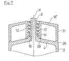
- FIG. 7 is a sectioned view of the axial end of the syringe according to the invention, according to a fourth embodiment of the invention.
- FIGS. 1 , 3 and 5 in each case show only the syringe cylinder, the plunger is not recognizable in the figures.
- the syringe shown in FIG. 1 in a known manner comprises a syringe cylinder 2 which is closed by a base 4 at a first, front axial end and at the opposite second axial end 6 is designed in an open manner, wherein a plunger can be introduced through the second axial end 6 into the inside of the syringe cylinder 2 in the known manner.
- the base 4 comprises a central opening, on which a Luer cone 8 is formed.
- the Luer cone 8 in its inside comprises an opening extending into the inside of the syringe cylinder 2 and forms the entry and exit opening of the syringe.
- the Luer connection with the syringe according to the invention is designed as a Luer-lock connection.
- a threaded sleeve 10 is arranged around the Luer cone 8 in a radially distanced manner and, on its inner periphery in the known manner, comprises an inner thread 12 and on its foot away from the base 4 comprises a radially inwardly directed shoulder 14 which engages into an annular groove 16 on the foot of the Luer cone 8 .
- the threaded sleeve 10 is secured on the Luer cone 8 in the axial direction X, but is rotatable about the longitudinal axis X relative to the Luer cone 8 , in order to be screwed to a counter piece which is applied on the Luer cone 8 and which engages into the free space between the Luer cone 8 and the threaded sleeve 10 , for the securement of this counter-piece.
- the threaded sleeve 10 comprises a radially outwardly directed prominence 18 .
- the prominence 18 is designed in an essentially disk-like manner and extends parallel to the base 4 of the syringe cylinder 2 .
- the disk-like prominence 18 with respect to the middle axis X has a slightly larger diameter than the syringe cylinder 2 at its base 4 .
- the prominence 18 thus with its edge projects outwards beyond the outer periphery of the syringe cylinder 2 and thus forms a peripheral gripping surface 20 , on which the prominence 18 and thus the threaded sleeve 10 can be gripped and rotated.
- the prominence 18 is provided with openings 22 which, in this case, are shaped such that the remaining webs between the openings 22 , as arrows, mark the rotation direction for the threaded sleeve 10 .
- FIGS. 3 and 4 show a second embodiment example of the invention, which differs from the embodiment example explained by way of FIGS. 1 and 2 merely in the design of the prominence 18 ′. All remaining features are identical.
- the prominence 18 ′ is designed as a closed disk with closed surface.
- the prominence 18 ′ completely covers the base 4 of the syringe cylinder 2 .
- the gripping surface 20 ′ on the outer periphery of the prominence 18 ′ in the example shown here is designed in a reeded manner, so that it permits a tighter grip.
- the third embodiment which is shown in the FIGS.
- the disk-like prominence 18 ′′ is designed in a closed manner, but is provided with an inscription 24 on the surface.
- the gripping surface 20 with this embodiment in turn is designed in a smooth manner, but could also be designed in a structured or reeded manner, as is shown in FIG. 3 .
- the prominence 18 , 18 ′, 18 ′′ extends essentially parallel to the base 4 at the axial end of the syringe cylinder 2 .
- the prominence 18 , 18 ′, 18 ′′ does not lie on the base 4 in a surfaced manner, but is led in a manner distanced to this.
- Webs are provided for this, specifically a web 26 which extends in the axial direction X on the outer periphery of the base 4 .
- the web 28 with its free end lies on the base 4 .
- the free end of the web 26 bears on the prominence 18 , 18 ′, 18 ′′.
- the prominence 18 ′′ in the region of its outer periphery comprises a thickening 30 which comes to lie on the web 26 .
- the prominence 18 , 18 ′, 18 ′′ is held in a manner distanced to the base 4 in the remaining regions, by which means the friction between the prominence 18 , 18 ′, 18 ′′ and the base 4 reduces.
- the thickening 30 on the outer periphery of the prominence 18 , 18 ′, 18 ′′ moreover has the advantage that the gripping surface 20 , 20 ′ is designed in a wider manner.
- the disk-like (disk or a disk portion) prominence 18 ′′′ in contrast to the third embodiment which is shown in FIG. 6 , is not arranged on the axial end of the threaded sleeve 10 which faces the syringe cylinder 2 , but at the opposite axial end of the threaded sleeve 10 which is away from the syringe cylinder 2 .
- the disk-like prominence 18 ′′′ in this case is also fixedly connected to the threaded sleeve 10 as with the previous embodiments, specifically integrally formed with this as one piece.
- the disk-like prominence 18 ′′′ extends essentially parallel to the base 4 of the syringe cylinder 2 .
- the disk-like prominence 18 ′ has a radius or diameter which is slightly larger than the outer radius of the syringe cylinder 2 .
- a cylindrical collar 31 which extends from the prominence 18 ′′′ towards the syringe cylinder 2 is arranged on the outer periphery of the disk-like prominence 18 ′.
- the collar 31 has an outer diameter which corresponds essentially to the outer diameter of the syringe cylinder 2 , so that it connects to this as an axial extension, in the axial direction.
- the cylindrical or peripheral collar 31 closes the free space 32 between the prominence 18 ′′′ and the base 4 of the syringe cylinder 2 , at the outer periphery. By way of this, the collar 31 prevents foreign matter from being able to penetrate into the free space 32 and simultaneously provides an increased gripping surface on the outer periphery, so that the prominence 18 ′′′ can be gripped and rotated even more simply.
- friction or clamping means can be arranged between the shoulder 14 and the groove 16 , for example by way of parts of the shoulder 14 or of the groove 16 being roughened.
- an eccentric arrangement between the shoulder 14 and groove 16 can be provided, in order given a rotation of the threaded sleeve 10 , to achieve a clamping between the shoulder 14 and groove 16 when the counter-piece is inserted, in order to prevent the threaded sleeve 10 from releasing in an unintended manner.
Abstract
Description
- This application claims the benefit of priority under 35 U.S.C. §119 of German
Patent Application DE 10 2012 214 718.7 filed Aug. 20, 2012, the entire contents of which are incorporated herein by reference. - The invention relates to a syringe, in particular to a medical syringe, with a syringe cylinder and with a Luer-lock connection which is arranged at an axial end of the syringe cylinder and which comprises a Luer cone and a rotatable threaded sleeve surrounding this.
- Syringes or medical syringes at their end as a rule comprise a Luer connection for the connection to a canulla or to a flexible tubing or likewise, which are to be connected. So-called Luer-lock connections are known, in order to secure this Luer connection, and these comprise an inner thread surrounding the Luer cone at a distance and screwed to the counter-connection. This on the one hand can be effected by way of rotation of the counter-connection, or however by way of rotating the thread, i.e. the threaded sleeve of the Luer-lock connection, for which the threaded sleeve is rotatably fastened on the Luer cone. The threaded sleeve however must be gripped on connecting, in order to rotate it. Thereby, there exists the danger that the fingers come into contact with the tip of the Luer cone itself, by which means regions which come into contact with the content of the syringe can become contaminated.
- With regard to this state of the art, it is an object of the invention to improve a syringe, in particular a medical syringe with a Luer-lock connection comprising a rotatable threaded sleeve, to the extent that a good handling ability with a simultaneously reduced danger of contamination is given.
- According to the invention a syringe is provided comprising a syringe cylinder and a Luer-lock connection arranged at an axial end of the syringe cylinder. The Luer-lock connection comprises a Luer cone and a rotatable threaded sleeve surrounding the Luer cone. The rotatable threaded sleeve comprises a radially outwardly directed prominence (projection, protuberance).
- With regard to the syringe according to the invention, it is particularly the case of a medical syringe which for example can serve for receiving and preparing medication. The syringe in the known manner comprises a syringe cylinder, in which a movable plunger can be arranged. Moreover, in the known manner, a Luer-lock connection is arranged at an axial end of the syringe cylinder. I.e. the connection comprises a Luer cone and a sleeve which has an inner thread and which peripherally surrounds this connection. According to the invention, thereby one envisages the threaded sleeve being rotatable. I.e. the engagement of the thread in the threaded sleeve with the counter-piece to be fastened on the Luer cone is effected by way of rotation of the threaded sleeve relative to this counter piece. The counter-piece thereby, with a corresponding thread or prominence, engages into the thread of the threaded sleeve.
- According to the invention, one envisages the rotatable threaded sleeve comprising a radially outwardly directed prominence. The prominence forms a grip region, on which the threaded sleeve can be gripped for its rotation. This prominence can be well gripped due to the fact that this prominence has a diameter which is enlarged compared to the diameter of the threaded sleeve. Moreover, the prominence provides a grip region which is remote from the tip of the Luer cone, since a radial distancing is given. Thus, the danger of the contact of the tip of the Luer cone on gripping the threaded sleeve is minimized. Moreover, the thus formed grip region on the outer periphery of the prominence, due to the greater diameter, has a better lever effect on rotating the threaded sleeve, which is advantageous if the threaded sleeve, as is described further below, is provided additionally with clamping means which fix the threaded sleeve after it has been tightened. A greater force is necessary for such a threaded sleeve for tightening, and this force can be mustered in a simpler manner via the grip region with a greater diameter which is formed by the prominence.
- According to a first preferred embodiment of the invention, the radially outwardly directed prominence is arranged at the axial end of the threaded sleeve which faces the syringe cylinder. This arrangement has the advantage that the prominence is distanced in the axial direction as far as possible from the tip of the Luer cone. Thus, the danger of contact of the syringe of the Luer cone on gripping the threaded sleeve is further minimized. Moreover, the prominence can thus be supported on the axial end of the syringe cylinder also in the axial direction, so that a greater stability is given, and for example a breaking away of the prominence due to pressure in the axial direction can be prevented.
- According to an alternative embodiment, it is however also possible for the radially outwardly directed prominence to be distanced in the axial direction from the axial end of the threaded sleeve which faces the syringe cylinder. Thereby, the prominence can be arranged on the axial end of the threaded sleeve which is away from the syringe cylinder or however also in an axial middle region between the two axial ends of the threaded sleeve. The axial distancing to the syringe cylinder can be advantageous in order to achieve a simpler rotatablity of the threaded sleeve, since the prominence of the threaded sleeve can thus be gripped more easily, without simultaneously firmly holding the syringe cylinder. A good compromise between an easy rotatablity and axial distance to the tip of the Luer cone can be achieved if the prominence is arranged in the axial middle region of the threaded sleeve.
- The radially outwardly directed prominence at its radially outer end at all events has a greater radius than the threaded sleeve on its outer periphery. Preferably, the radius of the prominence from the middle axis of the syringe cylinder is at least so large, that it corresponds to half the radius of the syringe cylinder at its axial end. This axial end is the axial end which faces the Luer cone. With this radius, it is ensured that the prominence can be well gripped from the outside. Further preferably, the radius of the prominence from the middle axis of the syringe cylinder corresponds to at least two thirds of the radius of the syringe cylinder at its axial end. Thus, the prominence can be gripped even better and on its outer periphery has an even greater radial distance to the Luer cone. According to a particularly preferred embodiment of the invention, the radius of the prominence from the middle axis of the syringe cylinder corresponds at least to the radius of the syringe cylinder at its axial end. With this embodiment, the prominence can be particularly well gripped, since its outer periphery corresponds at least to the outer periphery of the syringe cylinder at its axial end which faces the Luer cone.
- The radial or radially outwardly directed prominence is preferably designed in a disk-like manner. The disk-like prominence thereby further preferably has a circular shape and is arranged concentrically to the longitudinal axis or middle axis of the syringe cylinder. This is preferably also the axis, about which the threaded sleeve is rotatable. The prominence can be well gripped from all peripheral sides due to the disk-like design. Moreover, a large stability of the prominence is achieved and the base of the syringe cylinder, on which the Luer-lock connection is arranged, in the periphery of the Luer connection is preferably completely covered by the disk. The axial end of the syringe cylinder is simultaneously protected from damage by way of this.
- Particularly preferably, the prominence extends in a disk-like manner parallel to a base of the syringe cylinder which surrounds the Luer cone. The disk-like prominence merges harmonically into the overall shaping of the syringe by way of this. As mentioned above, the base of the syringe cylinder is simultaneously covered and protected from damage by the disk.
- According to a preferred embodiment, the disk-like prominence is designed in a closed manner. I.e. it completely covers the base of the syringe cylinder which surrounds the Luer cone and preferably has a closed surface. By way of this, one prevents contamination from being able to settle in the disk.
- Alternatively, the disk-like prominence can also be designed such that it comprises one or more openings. Such openings can serve for minimizing the material requirement. Moreover, the openings or structuring in the disk-like prominence serve its fashioning. For example, arrows which mark the rotation direction can be designed as openings or recesses or deepenings in the disk-like prominence. Other markings such as indications as to the contents of the syringe, the manufacturer etc. can also be applied on the disk-like prominence in the form of openings or structuring.
- Further preferably, the radial prominence has a radius which is greater than the radius of the syringe cylinder at its axial end. Preferably, the radial prominence projects radially at least slightly beyond the outer periphery of the base of the syringe cylinder. Thus, the prominence can be easily gripped on its outer periphery, without simultaneously gripping the syringe cylinder. Moreover, with a disk-like design of the prominence, the base of the syringe cylinder, which means the base at the end facing the Luer cone, is preferably completely covered and the disk-like prominence can be well gripped on the outer periphery of the syringe cylinder.
- Preferably, the prominence can be structured on its outer periphery. This permits a good gripping ability and force transmission on rotation.
- Moreover, the prominence in a further preferred embodiment can comprise an axially extending projection or collar, in a manner radially distanced to the threaded sleeve. The projection can be designed in the form of a thickening. The collar can preferably be designed in a sleeve-like manner. This means that the collar has a cylindrical shaping and preferably extends parallel to the longitudinal axis of the syringe cylinder or of the Luer cone. Thus, e.g. with a disk-like design of the prominence, the disk on the outer periphery can be thickened, so that an increased peripheral gripping surface is created, which renders it possible to grip and rotate the prominence on the outer periphery more easily. The axially extending projection can thereby extend away from the base of the syringe cylinder, i.e. extend essentially parallel to the longitudinal axis of the Luer cone. Alternatively or additionally, it can also extend in the opposite direction, for example by a certain amount parallel to the peripheral wall of the syringe cylinder and engage over this. Thus, an increased gripping surface is created at the outer periphery of the syringe cylinder. Preferably, a collar can extend from the prominence towards the cylinder in the axial direction, if the prominence is distanced in the axial direction to the axial end of the threaded sleeve which faces the syringe cylinder. Thus, the free space between the radial prominence and the base of the syringe cylinder is essentially peripherally closed by this collar. The collar thereby on the one hand forms an enlarged grip region, but on the other hand also prevents foreign bodies from being able to penetrate into the free space between the prominence and the syringe cylinder. Moreover, the collar or the projection can be supported on the base of the syringe cylinder in the axial direction, so that the prominence is supported given an axial pressure on the syringe cylinder. Preferably, a small distance remains between the projection or the collar and the base of the syringe cylinder, in order to ensure an easy rotatability of the threaded sleeve. This gap reduces with an axial pressure onto the radial prominence, until, in the extreme case, the collar can then come onto bearing contact on the axial end of the syringe cylinder.
- Particularly preferably, the projection or collar is arranged on the outer periphery of the radial prominence. Thereby, it further preferably connects to the outer periphery of the syringe cylinder in the axial extension, which leads to an optically aesthetic design.
- The threaded sleeve is rotatably fastened on the syringe cylinder, in particular on the Luer cone. For this, the threaded sleeve can comprise at least one inwardly directed projection, in particular a radially inwardly directed shoulder which engages into a groove on the foot of the Luer cone. Thus, the threaded sleeve is secured onto the Luer cone in the axial direction but is simultaneously rotatable. At least one friction means or clamping means can be arranged between the threaded sleeve and the Luer cone, in order to achieve a securing of the Luer-lock connection. A non-positive or positive fit engagement between the threaded sleeve and the foot of the Luer cone can be achieved by way of this, if the threaded sleeve is screwed to a counter-piece applied on the Luer cone. The threaded sleeve is prevented from inadvertently detaching again by way of this. This friction connection can be designed as is disclosed in German
patent application DE 10 2009 019 340 (corresponding US Patent Publication US 2012116355 is hereby incorporated by reference in its entirety). - The invention is hereinafter described by way of example and by way of the attached figures. The various features of novelty which characterize the invention are pointed out with particularity in the claims annexed to and forming a part of this disclosure. For a better understanding of the invention, its operating advantages and specific objects attained by its uses, reference is made to the accompanying drawings and descriptive matter in which preferred embodiments of the invention are illustrated.
- In the drawings:
-
FIG. 1 is a perspective entire view of a syringe according to the invention; -
FIG. 2 is a sectioned view of the axial end of the syringe according toFIG. 1 ; -
FIG. 3 is a perspective entire view of a syringe according to the second embodiment of the invention; -
FIG. 4 is a sectioned view of the axial end of the syringe according toFIG. 3 ; -
FIG. 5 is a perspective entire view of a syringe according to a third embodiment of the invention; -
FIG. 6 is a sectioned view of the axial end of the syringe according toFIGS. 5 ; and -
FIG. 7 is a sectioned view of the axial end of the syringe according to the invention, according to a fourth embodiment of the invention. - Referring to the drawings in particular,
FIGS. 1 , 3 and 5 in each case show only the syringe cylinder, the plunger is not recognizable in the figures. - The syringe shown in
FIG. 1 according to a first embodiment of the invention, in a known manner comprises asyringe cylinder 2 which is closed by abase 4 at a first, front axial end and at the opposite secondaxial end 6 is designed in an open manner, wherein a plunger can be introduced through the secondaxial end 6 into the inside of thesyringe cylinder 2 in the known manner. Thebase 4 comprises a central opening, on which aLuer cone 8 is formed. TheLuer cone 8 in its inside comprises an opening extending into the inside of thesyringe cylinder 2 and forms the entry and exit opening of the syringe. The Luer connection with the syringe according to the invention is designed as a Luer-lock connection. Thus, a threadedsleeve 10 is arranged around theLuer cone 8 in a radially distanced manner and, on its inner periphery in the known manner, comprises aninner thread 12 and on its foot away from thebase 4 comprises a radially inwardly directedshoulder 14 which engages into anannular groove 16 on the foot of theLuer cone 8. Thus, the threadedsleeve 10 is secured on theLuer cone 8 in the axial direction X, but is rotatable about the longitudinal axis X relative to theLuer cone 8, in order to be screwed to a counter piece which is applied on theLuer cone 8 and which engages into the free space between theLuer cone 8 and the threadedsleeve 10, for the securement of this counter-piece. - According to the invention, the threaded
sleeve 10 comprises a radially outwardly directedprominence 18. Theprominence 18 is designed in an essentially disk-like manner and extends parallel to thebase 4 of thesyringe cylinder 2. Thereby, the disk-like prominence 18 with respect to the middle axis X has a slightly larger diameter than thesyringe cylinder 2 at itsbase 4. Theprominence 18 thus with its edge projects outwards beyond the outer periphery of thesyringe cylinder 2 and thus forms a peripheralgripping surface 20, on which theprominence 18 and thus the threadedsleeve 10 can be gripped and rotated. This has the advantage that the threadedsleeve 10 does not have to be grasped in a region, in which there is the danger of the tip of theLuer cone 8 being touched and thereby contaminated. Moreover, thus a greater diameter for gripping the threadedsleeve 10 is provided, so that the threadedsleeve 10 can be rotated more easily. Moreover, the grippingsurface 20 lies radially outside the outer periphery of thesyringe cylinder 2, so that thesyringe cylinder 2 also does not hinder the gripping and rotation of the threadedsleeve 10. - In the example shown in
FIGS. 1 and 2 , theprominence 18 is provided withopenings 22 which, in this case, are shaped such that the remaining webs between theopenings 22, as arrows, mark the rotation direction for the threadedsleeve 10. -
FIGS. 3 and 4 show a second embodiment example of the invention, which differs from the embodiment example explained by way ofFIGS. 1 and 2 merely in the design of theprominence 18′. All remaining features are identical. With regard to the example shown inFIGS. 3 and 4 , theprominence 18′ is designed as a closed disk with closed surface. Thus, theprominence 18′ completely covers thebase 4 of thesyringe cylinder 2. Moreover, the grippingsurface 20′ on the outer periphery of theprominence 18′ in the example shown here is designed in a reeded manner, so that it permits a tighter grip. The third embodiment, which is shown in theFIGS. 5 and 6 , differs from the two first embodiments in that the disk-like prominence 18″ is designed in a closed manner, but is provided with aninscription 24 on the surface. Moreover, the grippingsurface 20 with this embodiment in turn is designed in a smooth manner, but could also be designed in a structured or reeded manner, as is shown inFIG. 3 . - With all three embodiment examples, the
prominence base 4 at the axial end of thesyringe cylinder 2. Thereby, theprominence base 4 in a surfaced manner, but is led in a manner distanced to this. Webs are provided for this, specifically aweb 26 which extends in the axial direction X on the outer periphery of thebase 4. Moreover, this is aweb 28 which in the region of the inner periphery of theprominence sleeve 10 in the opposite direction to this, axially away from theprominence web 28 with its free end lies on thebase 4. The free end of theweb 26 bears on theprominence prominence 18″ in the region of its outer periphery comprises a thickening 30 which comes to lie on theweb 26. In this manner, theprominence base 4 in the remaining regions, by which means the friction between theprominence base 4 reduces. The thickening 30 on the outer periphery of theprominence surface - With the fourth embodiment of the invention which is shown in
FIG. 7 , the disk-like (disk or a disk portion)prominence 18′″ in contrast to the third embodiment which is shown inFIG. 6 , is not arranged on the axial end of the threadedsleeve 10 which faces thesyringe cylinder 2, but at the opposite axial end of the threadedsleeve 10 which is away from thesyringe cylinder 2. The disk-like prominence 18′″ in this case is also fixedly connected to the threadedsleeve 10 as with the previous embodiments, specifically integrally formed with this as one piece. The disk-like prominence 18′″ extends essentially parallel to thebase 4 of thesyringe cylinder 2. In this case too, the disk-like prominence 18′ has a radius or diameter which is slightly larger than the outer radius of thesyringe cylinder 2. Acylindrical collar 31 which extends from theprominence 18′″ towards thesyringe cylinder 2 is arranged on the outer periphery of the disk-like prominence 18′. Thecollar 31 has an outer diameter which corresponds essentially to the outer diameter of thesyringe cylinder 2, so that it connects to this as an axial extension, in the axial direction. The cylindrical orperipheral collar 31 closes the free space 32 between theprominence 18′″ and thebase 4 of thesyringe cylinder 2, at the outer periphery. By way of this, thecollar 31 prevents foreign matter from being able to penetrate into the free space 32 and simultaneously provides an increased gripping surface on the outer periphery, so that theprominence 18′″ can be gripped and rotated even more simply. - Moreover, with all four embodiments, friction or clamping means can be arranged between the
shoulder 14 and thegroove 16, for example by way of parts of theshoulder 14 or of thegroove 16 being roughened. Here too, an eccentric arrangement between theshoulder 14 andgroove 16 can be provided, in order given a rotation of the threadedsleeve 10, to achieve a clamping between theshoulder 14 andgroove 16 when the counter-piece is inserted, in order to prevent the threadedsleeve 10 from releasing in an unintended manner. - While specific embodiments of the invention have been shown and described in detail to illustrate the application of the principles of the invention, it will be understood that the invention may be embodied otherwise without departing from such principles.
-
- 2—syringe cylinder
- 4—base
- 6—second axial end
- 8—Luer cone
- 10—threaded sleeve
- 12—inner thread
- 14—shoulder
- 16—groove
- 18, 18′, 18″, 18′″—prominence
- 20, 20′—gripping surface
- 22—openings
- 24—inscription
- 26—web
- 28—web
- 30—thickening
- 31—collar
- 32—free space
- X—longitudinal or middle axis
Claims (20)
Applications Claiming Priority (3)
| Application Number | Priority Date | Filing Date | Title |
|---|---|---|---|
| DE102012214718.7A DE102012214718A1 (en) | 2012-08-20 | 2012-08-20 | syringe |
| DE102012214718.7 | 2012-08-20 | ||
| DE102012214718 | 2012-08-20 |
Publications (2)
| Publication Number | Publication Date |
|---|---|
| US20140052078A1 true US20140052078A1 (en) | 2014-02-20 |
| US9033937B2 US9033937B2 (en) | 2015-05-19 |
Family
ID=49035294
Family Applications (1)
| Application Number | Title | Priority Date | Filing Date |
|---|---|---|---|
| US13/969,671 Active US9033937B2 (en) | 2012-08-20 | 2013-08-19 | Syringe |
Country Status (4)
| Country | Link |
|---|---|
| US (1) | US9033937B2 (en) |
| EP (1) | EP2700426B1 (en) |
| JP (1) | JP6731694B2 (en) |
| DE (1) | DE102012214718A1 (en) |
Cited By (4)
| Publication number | Priority date | Publication date | Assignee | Title |
|---|---|---|---|---|
| ITMI20150587A1 (en) * | 2015-04-24 | 2016-10-24 | Marchionni Marco | HIGHLY SAFE USE SYRINGE. |
| CN110740775A (en) * | 2017-06-12 | 2020-01-31 | 肖特瑞士股份公司 | Syringe with luer lock connector |
| US20200197942A1 (en) * | 2018-12-19 | 2020-06-25 | Fenwal, Inc. | Methods and systems for mating disposable syringes with pneumatic drivers without breaking sterility |
| US11350945B2 (en) | 2017-11-13 | 2022-06-07 | Merit Medical Systems, Inc. | Staged deflation syringe systems and associated methods |
Families Citing this family (1)
| Publication number | Priority date | Publication date | Assignee | Title |
|---|---|---|---|---|
| CA2987959A1 (en) * | 2015-07-06 | 2017-01-12 | Merit Medical Systems, Inc. | Reinforced syringe body |
Citations (6)
| Publication number | Priority date | Publication date | Assignee | Title |
|---|---|---|---|---|
| US5403288A (en) * | 1992-02-13 | 1995-04-04 | Stanners; Sydney D. | Safety sleeve for dental syringe |
| US5876379A (en) * | 1998-01-22 | 1999-03-02 | Alcon Laboratories, Inc. | Syringe cannula holder |
| US20040254538A1 (en) * | 2000-10-24 | 2004-12-16 | Murphy James P. | Delivery device for biological composites and method of preparation thereof |
| US20070088283A1 (en) * | 2003-09-25 | 2007-04-19 | Susumu Hongo | Medical use syringe |
| US20070265577A1 (en) * | 2004-04-07 | 2007-11-15 | Jms Co. Ltd. | Syringe with Connector, Connector for Syringe, and Syringe |
| US20120116355A1 (en) * | 2009-04-30 | 2012-05-10 | Transcoject Gmbh | Luer lock connection |
Family Cites Families (7)
| Publication number | Priority date | Publication date | Assignee | Title |
|---|---|---|---|---|
| AU3432789A (en) * | 1988-03-25 | 1989-10-16 | Merit Medical Systems, Inc. | Disposable control syringe |
| US5984373A (en) * | 1998-03-12 | 1999-11-16 | Elcam Plastic Kibbutz Bar-Am | Luer connector |
| JP4599875B2 (en) * | 2004-04-07 | 2010-12-15 | 株式会社ジェイ・エム・エス | Syringe with connector, connector used for syringe, and syringe |
| JP2005296137A (en) * | 2004-04-07 | 2005-10-27 | Jms Co Ltd | Syringe with connector, connector for use in syringe, and syringe |
| JP2005296141A (en) * | 2004-04-07 | 2005-10-27 | Jms Co Ltd | Syringe with connector and connector |
| DE202004012714U1 (en) * | 2004-08-12 | 2004-11-04 | Smiths Medical Deutschland Gmbh | Luer lock connector for medical devices |
| WO2006087763A1 (en) * | 2005-02-15 | 2006-08-24 | Kabushiki Kaisha Top | Connector |
-
2012
- 2012-08-20 DE DE102012214718.7A patent/DE102012214718A1/en not_active Withdrawn
-
2013
- 2013-08-13 EP EP13180186.2A patent/EP2700426B1/en active Active
- 2013-08-19 US US13/969,671 patent/US9033937B2/en active Active
- 2013-08-20 JP JP2013170087A patent/JP6731694B2/en active Active
Patent Citations (6)
| Publication number | Priority date | Publication date | Assignee | Title |
|---|---|---|---|---|
| US5403288A (en) * | 1992-02-13 | 1995-04-04 | Stanners; Sydney D. | Safety sleeve for dental syringe |
| US5876379A (en) * | 1998-01-22 | 1999-03-02 | Alcon Laboratories, Inc. | Syringe cannula holder |
| US20040254538A1 (en) * | 2000-10-24 | 2004-12-16 | Murphy James P. | Delivery device for biological composites and method of preparation thereof |
| US20070088283A1 (en) * | 2003-09-25 | 2007-04-19 | Susumu Hongo | Medical use syringe |
| US20070265577A1 (en) * | 2004-04-07 | 2007-11-15 | Jms Co. Ltd. | Syringe with Connector, Connector for Syringe, and Syringe |
| US20120116355A1 (en) * | 2009-04-30 | 2012-05-10 | Transcoject Gmbh | Luer lock connection |
Cited By (14)
| Publication number | Priority date | Publication date | Assignee | Title |
|---|---|---|---|---|
| CN107810024B (en) * | 2015-04-24 | 2021-08-17 | 卡洛·朱贝基奥 | Syringe with high safety in use |
| RU2746760C2 (en) * | 2015-04-24 | 2021-04-20 | Карло ДЖУБЕРКЬО | Syringe having high safety when used |
| CN107810024A (en) * | 2015-04-24 | 2018-03-16 | 卡洛·朱贝基奥 | There is the syringe of high security in use |
| US20180099103A1 (en) * | 2015-04-24 | 2018-04-12 | Marco MARCHIONNI | Syringe with high safety in use |
| JP2018512979A (en) * | 2015-04-24 | 2018-05-24 | ジュベルキオ, カルロGIUBERCHIO, Carlo | Highly safe syringe when in use |
| AU2016251625B2 (en) * | 2015-04-24 | 2021-02-18 | Carlo Giuberchio | Syringe with high safety in use |
| WO2016170150A1 (en) * | 2015-04-24 | 2016-10-27 | MARCHIONNI, Marco | Syringe with high safety in use |
| ITMI20150587A1 (en) * | 2015-04-24 | 2016-10-24 | Marchionni Marco | HIGHLY SAFE USE SYRINGE. |
| US11266793B2 (en) * | 2015-04-24 | 2022-03-08 | Aghetto S.R.L. | Syringe with high safety in use |
| CN110740775A (en) * | 2017-06-12 | 2020-01-31 | 肖特瑞士股份公司 | Syringe with luer lock connector |
| US11350945B2 (en) | 2017-11-13 | 2022-06-07 | Merit Medical Systems, Inc. | Staged deflation syringe systems and associated methods |
| US20200197942A1 (en) * | 2018-12-19 | 2020-06-25 | Fenwal, Inc. | Methods and systems for mating disposable syringes with pneumatic drivers without breaking sterility |
| US11684725B2 (en) | 2018-12-19 | 2023-06-27 | Fenwal, Inc. | Disposable syringe for use with pneumatic drivers |
| US11904147B2 (en) * | 2018-12-19 | 2024-02-20 | Fenwal, Inc. | Methods and systems for mating disposable syringes with pneumatic drivers without breaking sterility |
Also Published As
| Publication number | Publication date |
|---|---|
| DE102012214718A1 (en) | 2014-02-20 |
| US9033937B2 (en) | 2015-05-19 |
| EP2700426A1 (en) | 2014-02-26 |
| JP2014036864A (en) | 2014-02-27 |
| JP6731694B2 (en) | 2020-07-29 |
| EP2700426B1 (en) | 2018-04-04 |
Similar Documents
| Publication | Publication Date | Title |
|---|---|---|
| US9033937B2 (en) | Syringe | |
| US11779439B2 (en) | Coupling for a multi-part dental implant system | |
| JP6335907B2 (en) | ADAPTER FOR DRUG DELIVERY DEVICE AND METHOD FOR MOUNTING THIS ADAPTER ON THE DRUG DELIVERY DEVICE | |
| AU2013346797B2 (en) | Injection needle assembly | |
| JP2019069393A (en) | Adapter for drug delivery device and method of mounting the adapter thereon | |
| US9216278B2 (en) | Luer lock connection | |
| JP2016525395A5 (en) | ||
| AU2015217443B2 (en) | Rigid needle shield gripping cap assembly | |
| US9062785B2 (en) | Valve arrangement with a base part and an insert part | |
| JPH01107774A (en) | Safety unit | |
| JP2015533597A (en) | Syringe cap | |
| KR20070097428A (en) | Exchange needle retractable safety syringe | |
| EP3042689A1 (en) | Syringe and syringe set | |
| USD810310S1 (en) | Dupuytrens extender splint | |
| WO2012166527A3 (en) | Needle-protection device for a syringe | |
| JP2015516849A (en) | Drug delivery device | |
| US20180126091A1 (en) | Multi-Part Safety Device for a Syringe | |
| US9393360B2 (en) | Needle assembly storage device | |
| JP2011526193A5 (en) | ||
| KR101598495B1 (en) | Multi-Fixture Driver for Use In Dentistry | |
| WO2018002706A3 (en) | Accessory finger flange for syringe with a needle shield | |
| WO2011135209A3 (en) | Instrumented assembly for an axle journal | |
| WO2020015984A3 (en) | Medicament delivery device | |
| WO2011117840A3 (en) | Protection device with increased functionality, particularly for syringes and the like | |
| KR102529597B1 (en) | Syringe with high safety in use |
Legal Events
| Date | Code | Title | Description |
|---|---|---|---|
| AS | Assignment |
Owner name: TRANSCOJECT GMBH, GERMANY Free format text: ASSIGNMENT OF ASSIGNORS INTEREST;ASSIGNOR:HEINZ, JOCHEN, DR.;REEL/FRAME:031033/0717 Effective date: 20130805 |
|
| STCF | Information on status: patent grant |
Free format text: PATENTED CASE |
|
| MAFP | Maintenance fee payment |
Free format text: PAYMENT OF MAINTENANCE FEE, 4TH YR, SMALL ENTITY (ORIGINAL EVENT CODE: M2551); ENTITY STATUS OF PATENT OWNER: SMALL ENTITY Year of fee payment: 4 |
|
| MAFP | Maintenance fee payment |
Free format text: PAYMENT OF MAINTENANCE FEE, 8TH YR, SMALL ENTITY (ORIGINAL EVENT CODE: M2552); ENTITY STATUS OF PATENT OWNER: SMALL ENTITY Year of fee payment: 8 |