US20140000278A1 - Turbomachine thermal energy exchange - Google Patents
Turbomachine thermal energy exchange Download PDFInfo
- Publication number
- US20140000278A1 US20140000278A1 US13/604,052 US201213604052A US2014000278A1 US 20140000278 A1 US20140000278 A1 US 20140000278A1 US 201213604052 A US201213604052 A US 201213604052A US 2014000278 A1 US2014000278 A1 US 2014000278A1
- Authority
- US
- United States
- Prior art keywords
- turbomachine
- thermal energy
- compressed air
- section
- liquid
- Prior art date
- Legal status (The legal status is an assumption and is not a legal conclusion. Google has not performed a legal analysis and makes no representation as to the accuracy of the status listed.)
- Granted
Links
Images


Classifications
-
- F—MECHANICAL ENGINEERING; LIGHTING; HEATING; WEAPONS; BLASTING
- F02—COMBUSTION ENGINES; HOT-GAS OR COMBUSTION-PRODUCT ENGINE PLANTS
- F02C—GAS-TURBINE PLANTS; AIR INTAKES FOR JET-PROPULSION PLANTS; CONTROLLING FUEL SUPPLY IN AIR-BREATHING JET-PROPULSION PLANTS
- F02C3/00—Gas-turbine plants characterised by the use of combustion products as the working fluid
- F02C3/20—Gas-turbine plants characterised by the use of combustion products as the working fluid using a special fuel, oxidant, or dilution fluid to generate the combustion products
- F02C3/30—Adding water, steam or other fluids for influencing combustion, e.g. to obtain cleaner exhaust gases
-
- F—MECHANICAL ENGINEERING; LIGHTING; HEATING; WEAPONS; BLASTING
- F02—COMBUSTION ENGINES; HOT-GAS OR COMBUSTION-PRODUCT ENGINE PLANTS
- F02C—GAS-TURBINE PLANTS; AIR INTAKES FOR JET-PROPULSION PLANTS; CONTROLLING FUEL SUPPLY IN AIR-BREATHING JET-PROPULSION PLANTS
- F02C7/00—Features, components parts, details or accessories, not provided for in, or of interest apart form groups F02C1/00 - F02C6/00; Air intakes for jet-propulsion plants
- F02C7/12—Cooling of plants
- F02C7/16—Cooling of plants characterised by cooling medium
- F02C7/18—Cooling of plants characterised by cooling medium the medium being gaseous, e.g. air
- F02C7/185—Cooling means for reducing the temperature of the cooling air or gas
-
- F—MECHANICAL ENGINEERING; LIGHTING; HEATING; WEAPONS; BLASTING
- F05—INDEXING SCHEMES RELATING TO ENGINES OR PUMPS IN VARIOUS SUBCLASSES OF CLASSES F01-F04
- F05D—INDEXING SCHEME FOR ASPECTS RELATING TO NON-POSITIVE-DISPLACEMENT MACHINES OR ENGINES, GAS-TURBINES OR JET-PROPULSION PLANTS
- F05D2260/00—Function
- F05D2260/20—Heat transfer, e.g. cooling
- F05D2260/212—Heat transfer, e.g. cooling by water injection
-
- F—MECHANICAL ENGINEERING; LIGHTING; HEATING; WEAPONS; BLASTING
- F05—INDEXING SCHEMES RELATING TO ENGINES OR PUMPS IN VARIOUS SUBCLASSES OF CLASSES F01-F04
- F05D—INDEXING SCHEME FOR ASPECTS RELATING TO NON-POSITIVE-DISPLACEMENT MACHINES OR ENGINES, GAS-TURBINES OR JET-PROPULSION PLANTS
- F05D2260/00—Function
- F05D2260/20—Heat transfer, e.g. cooling
- F05D2260/213—Heat transfer, e.g. cooling by the provision of a heat exchanger within the cooling circuit
-
- Y—GENERAL TAGGING OF NEW TECHNOLOGICAL DEVELOPMENTS; GENERAL TAGGING OF CROSS-SECTIONAL TECHNOLOGIES SPANNING OVER SEVERAL SECTIONS OF THE IPC; TECHNICAL SUBJECTS COVERED BY FORMER USPC CROSS-REFERENCE ART COLLECTIONS [XRACs] AND DIGESTS
- Y02—TECHNOLOGIES OR APPLICATIONS FOR MITIGATION OR ADAPTATION AGAINST CLIMATE CHANGE
- Y02T—CLIMATE CHANGE MITIGATION TECHNOLOGIES RELATED TO TRANSPORTATION
- Y02T50/00—Aeronautics or air transport
- Y02T50/60—Efficient propulsion technologies, e.g. for aircraft
Definitions
- a fluid such as water
- the fluid may augment power output and decrease nitrogen oxide emissions.
- the turbomachine may be an industrial turbomachine.
- the method may include receiving the compressed air from a compression section of the turbomachine.
- the method may include heating the water within a heat exchanger.
- the heat exchanger may be within a core of the engine.
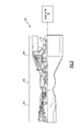
- FIG. 1 shows a schematic view of an example turbomachine used for propulsion.
- FIG. 2 shows an example industrial turbomachine.
- FIG. 3 shows a highly-schematic view of a thermal energy exchange arrangement within the industrial turbomachine of FIG. 2 .
- FIG. 4 shows the flow of an example method of thermal energy exchange within a turbomachine.
- turbofan gas turbine engine Although depicted as a two-spool turbofan gas turbine engine in the disclosed non-limiting embodiment, it should be understood that the concepts described herein are not limited to use with turbofans. That is, the teachings may be applied to other types of turbomachines and turbine engines including three-spool architectures. Further, the concepts described herein could be used in environments other than a turbomachine environment and in applications other than aerospace applications, such as automotive applications.
- the example engine 20 generally includes a low-speed spool 30 and a high-speed spool 32 mounted for rotation about an engine central axis A.
- the low-speed spool 30 and the high-speed spool 32 are rotatably supported by several bearing systems 38 . It should be understood that various bearing systems 38 at various locations may alternatively, or additionally, be provided.
- the low-speed spool 30 generally includes a shaft 40 that interconnects a fan 42 , a low-pressure compressor 44 , and a low-pressure turbine 46 .
- the shaft 40 is connected to the fan 42 through a geared architecture 48 to drive the fan 42 at a lower speed than the low-speed spool 30 .
- the shaft 40 and the shaft 50 are concentric and rotate via bearing systems 38 about the engine central longitudinal axis A, which is collinear with the longitudinal axes of the shaft 40 and the shaft 50 .
- the combustion section 26 includes a circumferentially distributed array of combustors 56 generally arranged axially between the high-pressure compressor 52 and the high-pressure turbine 54 .
- the engine 20 is a high-bypass geared aircraft engine. In a further example, the engine 20 bypass ratio is greater than about six (6 to 1).
- the low-pressure turbine 46 pressure ratio is pressure measured prior to inlet of low-pressure turbine 46 as related to the pressure at the outlet of the low-pressure turbine 46 prior to an exhaust nozzle of the engine 20 .
- the bypass ratio of the engine 20 is greater than about ten (10 to 1)
- the fan diameter is significantly larger than that of the low pressure compressor 44
- the low-pressure turbine 46 has a pressure ratio that is greater than about 5 (5 to 1).
- the geared architecture 48 of this embodiment is an epicyclic gear train with a gear reduction ratio of greater than about 2.5 (2.5 to 1). It should be understood, however, that the above parameters are only exemplary of one embodiment of a geared architecture engine and that the present disclosure is applicable to other gas turbine engines including direct drive turbofans.
- compressed air from the compression section 64 is mixed with fuel and combusted in the combustion section 66 .
- the products of combustion expand through the turbine section 68 .
- Expansion in the turbine section 68 rotates rotors 70 of the engine 60 .
- the rotors 70 rotatably drive an electric generator 76 to produce electrical power in a known manner.
- the combustion section 66 is a portion of the core engine. Fluid is also may be injected into other portions of the core engine.
- thermal energy moves from the air within the path 82 to the fluid within the path 78 . This exchange of thermal energy raises the temperature of the fluid and lowers the temperature of the cooling air.
- an example method 100 of thermal energy exchange within the turbomachine includes a step 110 of heating a liquid using thermal energy from compressed air.
- the method 100 also includes a step 120 of injecting the liquid into a portion of a turbomachine.
Landscapes
- Engineering & Computer Science (AREA)
- Chemical & Material Sciences (AREA)
- Combustion & Propulsion (AREA)
- Mechanical Engineering (AREA)
- General Engineering & Computer Science (AREA)
- Engine Equipment That Uses Special Cycles (AREA)
- Structures Of Non-Positive Displacement Pumps (AREA)
Abstract
Description
- This disclosure claims priority to U.S. Provisional Application No. 61/667,120, which was filed on Jul. 2, 2012, and is incorporated herein by reference.
- This disclosure relates to exchanging thermal energy and, more particularly, to thermal energy exchange within a turbomachine.
- Turbomachines, such as gas turbine engines, typically include at least a compression section, a combustion section, and a turbine section. Turbomachines may employ a geared architecture connecting the portions of the compression section to the turbine section.
- During operation, compressed air from the compression section is mixed with fuel and combusted in the combustion section. The products of combustion are expanded to rotatably drive the turbine section. The rotating portions of the turbine section may rotatably power a generator, for example.
- In some turbomachines, a fluid, such as water, is injected into the combustion section during operation. The fluid may augment power output and decrease nitrogen oxide emissions.
- A method of thermal energy exchange within a turbomachine according to an exemplary aspect of the present disclosure includes, among other things, heating a liquid using thermal energy from compressed air, injecting the liquid into a first portion of a turbomachine, and using the compressed air to cool a second portion of the turbomachine.
- In a further non-limiting embodiment of the foregoing method, the turbomachine may be an industrial turbomachine.
- In a further non-limiting embodiment of either of the foregoing methods, the compressed air may be bleed air from a compression section of the turbomachine.
- In a further non-limiting embodiment of any of the foregoing methods, the liquid may be water.
- In a further non-limiting embodiment of any of the foregoing methods, the method may include communicating the compressed air to a turbine section of the turbomachine after the heating.
- In a further non-limiting embodiment of any of the foregoing methods, the first portion of the turbomachine may be a combustion section of the turbomachine.
- In a further non-limiting embodiment of any of the foregoing methods, the method may include heating the liquid within a heat exchanger.
- A method of thermal energy exchange within a turbomachine according to another exemplary aspect of the present disclosure includes, among other things, heating water using thermal energy from compressed air, communicating the water to a combustion section of a turbomachine after the heating, and communicating the compressed air to a turbine section of the turbomachine after the heating.
- In a further non-limiting embodiment of the foregoing method, the turbomachine may be an industrial turbomachine.
- In a further non-limiting embodiment of either of the foregoing methods, the method may include receiving the compressed air from a compression section of the turbomachine.
- In a further non-limiting embodiment of any of the foregoing methods, the method may include heating the water within a heat exchanger.
- In a further non-limiting embodiment of any of the foregoing methods, the heat exchanger may be within a core of the engine.
- A thermal energy exchanging arrangement according to another exemplary aspect of the present disclosure includes, among other things, a heat exchanger configured to receive a liquid at a first temperature and to heat the liquid to a second, higher temperature using compressed air from a compression section of a turbomachine, a combustion section of the turbomachine that receives the liquid from the heat exchanger, and a turbine section of the turbomachine that receives the compressed air from the heat exchanger.
- In a further non-limiting embodiment of the foregoing thermal energy exchanging arrangement, the liquid may be a water.
- In a further non-limiting embodiment of the foregoing thermal energy exchanging arrangement, the combustion section may be within an industrial turbomachine.
- The various features and advantages of the disclosed examples will become apparent to those skilled in the art from the detailed description. The figures that accompany the detailed description can be briefly described as follows:
-
FIG. 1 shows a schematic view of an example turbomachine used for propulsion. -
FIG. 2 shows an example industrial turbomachine. -
FIG. 3 shows a highly-schematic view of a thermal energy exchange arrangement within the industrial turbomachine ofFIG. 2 . -
FIG. 4 shows the flow of an example method of thermal energy exchange within a turbomachine. -
FIG. 1 schematically illustrates an example turbomachine, which is agas turbine engine 20 in this example. Thegas turbine engine 20 is a two-spool turbofan gas turbine engine that generally includes afan section 22, acompression section 24, a combustion section 26, and aturbine section 28. - Although depicted as a two-spool turbofan gas turbine engine in the disclosed non-limiting embodiment, it should be understood that the concepts described herein are not limited to use with turbofans. That is, the teachings may be applied to other types of turbomachines and turbine engines including three-spool architectures. Further, the concepts described herein could be used in environments other than a turbomachine environment and in applications other than aerospace applications, such as automotive applications.
- In the
example engine 20, flow moves from thefan section 22 to a bypass flowpath. Flow from the bypass flowpath generates forward thrust. Thecompression section 24 drives air along the core flowpath. Compressed air from thecompression section 24 communicates through the combustion section 26. The products of combustion expand through theturbine section 28. - The
example engine 20 generally includes a low-speed spool 30 and a high-speed spool 32 mounted for rotation about an engine central axis A. The low-speed spool 30 and the high-speed spool 32 are rotatably supported byseveral bearing systems 38. It should be understood thatvarious bearing systems 38 at various locations may alternatively, or additionally, be provided. - The low-
speed spool 30 generally includes ashaft 40 that interconnects afan 42, a low-pressure compressor 44, and a low-pressure turbine 46. Theshaft 40 is connected to thefan 42 through a gearedarchitecture 48 to drive thefan 42 at a lower speed than the low-speed spool 30. - The high-
speed spool 32 includes a shaft 50 that interconnects a high-pressure compressor 52 and high-pressure turbine 54. - The
shaft 40 and the shaft 50 are concentric and rotate viabearing systems 38 about the engine central longitudinal axis A, which is collinear with the longitudinal axes of theshaft 40 and the shaft 50. - The combustion section 26 includes a circumferentially distributed array of
combustors 56 generally arranged axially between the high-pressure compressor 52 and the high-pressure turbine 54. - In some non-limiting examples, the
engine 20 is a high-bypass geared aircraft engine. In a further example, theengine 20 bypass ratio is greater than about six (6 to 1). - The geared
architecture 48 of theexample engine 20 includes an epicyclic gear train, such as a planetary gear system or other gear system. The example epicyclic gear train has a gear reduction ratio of greater than about 2.3 (2.3 to 1). - The low-
pressure turbine 46 pressure ratio is pressure measured prior to inlet of low-pressure turbine 46 as related to the pressure at the outlet of the low-pressure turbine 46 prior to an exhaust nozzle of theengine 20. In one non-limiting embodiment, the bypass ratio of theengine 20 is greater than about ten (10 to 1), the fan diameter is significantly larger than that of thelow pressure compressor 44, and the low-pressure turbine 46 has a pressure ratio that is greater than about 5 (5 to 1). The gearedarchitecture 48 of this embodiment is an epicyclic gear train with a gear reduction ratio of greater than about 2.5 (2.5 to 1). It should be understood, however, that the above parameters are only exemplary of one embodiment of a geared architecture engine and that the present disclosure is applicable to other gas turbine engines including direct drive turbofans. - In this embodiment of the
example engine 20, a significant amount of thrust is provided by the bypass flow B due to the high bypass ratio. Thefan section 22 of theengine 20 is designed for a particular flight condition—typically cruise at about 0.8 Mach and about 35,000 feet. This flight condition, with theengine 20 at its best fuel consumption, is also known as “Bucket Cruise” Thrust Specific Fuel Consumption (TSFC). TSFC is an industry standard parameter of fuel consumption per unit of thrust. - Fan Pressure Ratio is the pressure ratio across a blade of the
fan section 22 without the use of a Fan Exit Guide Vane system. The low Fan Pressure Ratio according to one non-limiting embodiment of theexample engine 20 is less than 1.45 (1.45 to 1). - Low Corrected Fan Tip Speed is the actual fan tip speed divided by an industry standard temperature correction of Temperature divided by 518.7 ̂ 0.5. The Temperature represents the ambient temperature in degrees Rankine. The Low Corrected Fan Tip Speed according to one non-limiting embodiment of the
example engine 20 is less than about 1150 fps (351 m/s). - Referring now to
FIGS. 2 and 3 , another example turbomachine is an industrialgas turbine engine 60. The exampleindustrial engine 60 is a land-based, two-spool turbofan gas turbine engine that generally includes acompression section 64, acombustion section 66, and aturbine section 68. - In the
example engine 60, compressed air from thecompression section 64 is mixed with fuel and combusted in thecombustion section 66. The products of combustion expand through theturbine section 68. Expansion in theturbine section 68 rotatesrotors 70 of theengine 60. Therotors 70 rotatably drive anelectric generator 76 to produce electrical power in a known manner. - During operation of the
engine 60, fluid, such as water, is injected into the combustors within thecombustion section 66. The fluid augments power output from theengine 60 and decreases emissions of nitrogen oxides. - The
combustion section 66 is a portion of the core engine. Fluid is also may be injected into other portions of the core engine. - The
engine 60 includes a manifold that directs fluid from afluid source 80 to thecombustion section 66. The manifold is represented bypath 78 in this example. - The
example engine 60 includes aheat exchanger 84 that adds thermal energy to the fluid before the fluid is injected into thecombustion section 66. In this example, cooling air bled from thecompression section 64 of theengine 60 is moved through theheat exchanger 84 to add thermal energy to the fluid before the fluid is injected into the combustion section. Theexample heat exchanger 84 is located axially between a low-speed compressor and a high-speed compressor within thecompression section 64. - Compressed air from the
compression section 64 moves alongpath 82 from thecompression section 64 to theturbine section 68. The compressed air is used to cool components in theturbine section 68, and specifically the inner surfaces of those components. The compressed air within thepath 82 is bled from relatively early stages of thecompression section 64, such as from stage 2, 3, or 4. Although eventually used for cooling, the air from thecompression section 64 is heated relative to the fluid moving along thepath 78. - Within the
heat exchanger 84, thermal energy moves from the air within thepath 82 to the fluid within thepath 78. This exchange of thermal energy raises the temperature of the fluid and lowers the temperature of the cooling air. - Referring to
FIG. 4 with continuing reference toFIG. 3 , anexample method 100 of thermal energy exchange within the turbomachine includes astep 110 of heating a liquid using thermal energy from compressed air. Themethod 100 also includes astep 120 of injecting the liquid into a portion of a turbomachine. - The preceding description is exemplary rather than limiting in nature. Variations and modifications to the disclosed examples may become apparent to those skilled in the art that do not necessarily depart from the essence of this disclosure. Thus, the scope of legal protection given to this disclosure can only be determined by studying the following claims.
Claims (15)
Priority Applications (3)
| Application Number | Priority Date | Filing Date | Title |
|---|---|---|---|
| US13/604,052 US9086019B2 (en) | 2012-07-02 | 2012-09-05 | Turbomachine thermal energy exchange |
| EP13813874.8A EP2867497B1 (en) | 2012-07-02 | 2013-06-21 | Turbomachine thermal energy exchange |
| PCT/US2013/046962 WO2014008005A1 (en) | 2012-07-02 | 2013-06-21 | Turbomachine thermal energy exchange |
Applications Claiming Priority (2)
| Application Number | Priority Date | Filing Date | Title |
|---|---|---|---|
| US201261667120P | 2012-07-02 | 2012-07-02 | |
| US13/604,052 US9086019B2 (en) | 2012-07-02 | 2012-09-05 | Turbomachine thermal energy exchange |
Publications (2)
| Publication Number | Publication Date |
|---|---|
| US20140000278A1 true US20140000278A1 (en) | 2014-01-02 |
| US9086019B2 US9086019B2 (en) | 2015-07-21 |
Family
ID=49776725
Family Applications (1)
| Application Number | Title | Priority Date | Filing Date |
|---|---|---|---|
| US13/604,052 Active 2033-11-14 US9086019B2 (en) | 2012-07-02 | 2012-09-05 | Turbomachine thermal energy exchange |
Country Status (3)
| Country | Link |
|---|---|
| US (1) | US9086019B2 (en) |
| EP (1) | EP2867497B1 (en) |
| WO (1) | WO2014008005A1 (en) |
Cited By (2)
| Publication number | Priority date | Publication date | Assignee | Title |
|---|---|---|---|---|
| US20170168318A1 (en) * | 2014-08-21 | 2017-06-15 | Johnson & Johnson Vision Care, Inc. | Device and methods for sealing and encapsulation for biocompatible energization elements |
| US11473441B2 (en) * | 2016-09-28 | 2022-10-18 | General Electric Company | Embedded electric machine |
Citations (7)
| Publication number | Priority date | Publication date | Assignee | Title |
|---|---|---|---|---|
| US4767259A (en) * | 1985-07-29 | 1988-08-30 | Hitachi, Ltd. | Cooling air flow controlling apparatus for gas turbine |
| US5161365A (en) * | 1990-12-05 | 1992-11-10 | Allied-Signal Inc. | Endothermic fuel power generator and method |
| US5317877A (en) * | 1992-08-03 | 1994-06-07 | General Electric Company | Intercooled turbine blade cooling air feed system |
| US5611197A (en) * | 1995-10-23 | 1997-03-18 | General Electric Company | Closed-circuit air cooled turbine |
| US5697208A (en) * | 1995-06-02 | 1997-12-16 | Solar Turbines Incorporated | Turbine cooling cycle |
| US5722241A (en) * | 1996-02-26 | 1998-03-03 | Westinghouse Electric Corporation | Integrally intercooled axial compressor and its application to power plants |
| US6298656B1 (en) * | 2000-09-29 | 2001-10-09 | Siemens Westinghouse Power Corporation | Compressed air steam generator for cooling combustion turbine transition section |
Family Cites Families (16)
| Publication number | Priority date | Publication date | Assignee | Title |
|---|---|---|---|---|
| US4137705A (en) | 1977-07-25 | 1979-02-06 | General Electric Company | Cooling air cooler for a gas turbine engine |
| US4395874A (en) | 1980-12-02 | 1983-08-02 | United Technologies Corporation | Fuel nozzles with water injection for gas turbine engines |
| US5160096A (en) | 1991-10-11 | 1992-11-03 | United Technologies Corporation | Gas turbine cycle |
| US5255505A (en) | 1992-02-21 | 1993-10-26 | Westinghouse Electric Corp. | System for capturing heat transferred from compressed cooling air in a gas turbine |
| US5564271A (en) | 1994-06-24 | 1996-10-15 | United Technologies Corporation | Pressure vessel fuel nozzle support for an industrial gas turbine engine |
| WO1997003281A1 (en) | 1995-07-10 | 1997-01-30 | Westinghouse Electric Corporation | Preheating of gas turbine fuel with compressed cooling air |
| US6430931B1 (en) * | 1997-10-22 | 2002-08-13 | General Electric Company | Gas turbine in-line intercooler |
| US6295803B1 (en) | 1999-10-28 | 2001-10-02 | Siemens Westinghouse Power Corporation | Gas turbine cooling system |
| EP1199445A1 (en) | 2000-10-17 | 2002-04-24 | Siemens Aktiengesellschaft | Apparatus and method of fuel preheating in combined gas and steam turbine plants |
| US6427447B1 (en) | 2001-02-06 | 2002-08-06 | United Technologies Corporation | Bulkhead for dual fuel industrial and aeroengine gas turbines |
| US6536026B2 (en) | 2001-06-30 | 2003-03-18 | Motorola, Inc. | Method and apparatus for analyzing small signal response and noise in nonlinear circuits |
| US7284377B2 (en) | 2004-05-28 | 2007-10-23 | General Electric Company | Method and apparatus for operating an intercooler for a gas turbine engine |
| US7487642B2 (en) | 2005-11-01 | 2009-02-10 | General Electric Comapny | Methods and apparatus for operating gas turbine engines |
| US7874156B2 (en) | 2007-03-29 | 2011-01-25 | General Electric Company | Methods and apparatus for heating a fluid |
| US7647777B2 (en) | 2008-06-20 | 2010-01-19 | Gas Turbine Efficiency Sweden Ab | Skid architecture for a power augmentation system |
| US20100107592A1 (en) | 2008-11-04 | 2010-05-06 | General Electric Company | System and method for reducing corrosion in a gas turbine system |
-
2012
- 2012-09-05 US US13/604,052 patent/US9086019B2/en active Active
-
2013
- 2013-06-21 EP EP13813874.8A patent/EP2867497B1/en active Active
- 2013-06-21 WO PCT/US2013/046962 patent/WO2014008005A1/en not_active Ceased
Patent Citations (7)
| Publication number | Priority date | Publication date | Assignee | Title |
|---|---|---|---|---|
| US4767259A (en) * | 1985-07-29 | 1988-08-30 | Hitachi, Ltd. | Cooling air flow controlling apparatus for gas turbine |
| US5161365A (en) * | 1990-12-05 | 1992-11-10 | Allied-Signal Inc. | Endothermic fuel power generator and method |
| US5317877A (en) * | 1992-08-03 | 1994-06-07 | General Electric Company | Intercooled turbine blade cooling air feed system |
| US5697208A (en) * | 1995-06-02 | 1997-12-16 | Solar Turbines Incorporated | Turbine cooling cycle |
| US5611197A (en) * | 1995-10-23 | 1997-03-18 | General Electric Company | Closed-circuit air cooled turbine |
| US5722241A (en) * | 1996-02-26 | 1998-03-03 | Westinghouse Electric Corporation | Integrally intercooled axial compressor and its application to power plants |
| US6298656B1 (en) * | 2000-09-29 | 2001-10-09 | Siemens Westinghouse Power Corporation | Compressed air steam generator for cooling combustion turbine transition section |
Cited By (2)
| Publication number | Priority date | Publication date | Assignee | Title |
|---|---|---|---|---|
| US20170168318A1 (en) * | 2014-08-21 | 2017-06-15 | Johnson & Johnson Vision Care, Inc. | Device and methods for sealing and encapsulation for biocompatible energization elements |
| US11473441B2 (en) * | 2016-09-28 | 2022-10-18 | General Electric Company | Embedded electric machine |
Also Published As
| Publication number | Publication date |
|---|---|
| WO2014008005A1 (en) | 2014-01-09 |
| EP2867497A4 (en) | 2015-07-22 |
| EP2867497A1 (en) | 2015-05-06 |
| EP2867497B1 (en) | 2020-12-09 |
| US9086019B2 (en) | 2015-07-21 |
Similar Documents
| Publication | Publication Date | Title |
|---|---|---|
| US11560839B2 (en) | Gas turbine engine buffer system | |
| US20170306847A1 (en) | Combined Drive for Cooling Air Using Cooing Compressor and Aircraft Air Supply Pump | |
| US10107157B2 (en) | Gas turbine engine lubrication system | |
| US20170082028A1 (en) | Intercooled cooling air using existing heat exchanger | |
| US9328626B2 (en) | Annular turbomachine seal and heat shield | |
| EP3348810B1 (en) | Injection cooled cooling air system for a gas turbine engine and a corresponding method | |
| EP3126640B1 (en) | Active clearance control for gas turbine engine | |
| US20160047259A1 (en) | Gas turbine engine stress isolation scallop | |
| US10837364B2 (en) | Thermal shield for gas turbine engine diffuser case | |
| EP3330515B1 (en) | Gas turbine engine | |
| EP3219959B1 (en) | Intercooled cooling air using existing heat exchanger | |
| US9086019B2 (en) | Turbomachine thermal energy exchange | |
| EP2959149B1 (en) | Gas turbine engine core utilized in both commercial and military engines | |
| US12031478B2 (en) | Air bottoming cycle driven propulsor | |
| EP3056668A1 (en) | High pressure compressor rotor thermal conditioning using conditioned compressor air | |
| US10823071B2 (en) | Multi-source turbine cooling air |
Legal Events
| Date | Code | Title | Description |
|---|---|---|---|
| AS | Assignment |
Owner name: UNITED TECHNOLOGIES CORPORATION, CONNECTICUT Free format text: ASSIGNMENT OF ASSIGNORS INTEREST;ASSIGNOR:WINTER, MICHAEL;REEL/FRAME:028900/0653 Effective date: 20120905 |
|
| STCF | Information on status: patent grant |
Free format text: PATENTED CASE |
|
| MAFP | Maintenance fee payment |
Free format text: PAYMENT OF MAINTENANCE FEE, 4TH YEAR, LARGE ENTITY (ORIGINAL EVENT CODE: M1551); ENTITY STATUS OF PATENT OWNER: LARGE ENTITY Year of fee payment: 4 |
|
| AS | Assignment |
Owner name: RAYTHEON TECHNOLOGIES CORPORATION, MASSACHUSETTS Free format text: CHANGE OF NAME;ASSIGNOR:UNITED TECHNOLOGIES CORPORATION;REEL/FRAME:054062/0001 Effective date: 20200403 |
|
| AS | Assignment |
Owner name: RAYTHEON TECHNOLOGIES CORPORATION, CONNECTICUT Free format text: CORRECTIVE ASSIGNMENT TO CORRECT THE AND REMOVE PATENT APPLICATION NUMBER 11886281 AND ADD PATENT APPLICATION NUMBER 14846874. TO CORRECT THE RECEIVING PARTY ADDRESS PREVIOUSLY RECORDED AT REEL: 054062 FRAME: 0001. ASSIGNOR(S) HEREBY CONFIRMS THE CHANGE OF ADDRESS;ASSIGNOR:UNITED TECHNOLOGIES CORPORATION;REEL/FRAME:055659/0001 Effective date: 20200403 |
|
| MAFP | Maintenance fee payment |
Free format text: PAYMENT OF MAINTENANCE FEE, 8TH YEAR, LARGE ENTITY (ORIGINAL EVENT CODE: M1552); ENTITY STATUS OF PATENT OWNER: LARGE ENTITY Year of fee payment: 8 |
|
| AS | Assignment |
Owner name: RTX CORPORATION, CONNECTICUT Free format text: CHANGE OF NAME;ASSIGNOR:RAYTHEON TECHNOLOGIES CORPORATION;REEL/FRAME:064714/0001 Effective date: 20230714 |