US20130177458A1 - Dry-type cable wire outlet device for a submersible electrical pump - Google Patents
Dry-type cable wire outlet device for a submersible electrical pump Download PDFInfo
- Publication number
- US20130177458A1 US20130177458A1 US13/786,648 US201313786648A US2013177458A1 US 20130177458 A1 US20130177458 A1 US 20130177458A1 US 201313786648 A US201313786648 A US 201313786648A US 2013177458 A1 US2013177458 A1 US 2013177458A1
- Authority
- US
- United States
- Prior art keywords
- wire outlet
- cable
- sealing
- electrical pump
- submersible electrical
- Prior art date
- Legal status (The legal status is an assumption and is not a legal conclusion. Google has not performed a legal analysis and makes no representation as to the accuracy of the status listed.)
- Granted
Links
- 238000007789 sealing Methods 0.000 claims abstract description 83
- XLYOFNOQVPJJNP-UHFFFAOYSA-N water Substances O XLYOFNOQVPJJNP-UHFFFAOYSA-N 0.000 description 17
- 229910000831 Steel Inorganic materials 0.000 description 2
- 230000003247 decreasing effect Effects 0.000 description 2
- 239000010959 steel Substances 0.000 description 2
- 238000010276 construction Methods 0.000 description 1
- 230000000694 effects Effects 0.000 description 1
- 238000000034 method Methods 0.000 description 1
- 230000002035 prolonged effect Effects 0.000 description 1
- 230000000630 rising effect Effects 0.000 description 1
- 238000005406 washing Methods 0.000 description 1
- 238000009736 wetting Methods 0.000 description 1
Images

Classifications
-
- H—ELECTRICITY
- H02—GENERATION; CONVERSION OR DISTRIBUTION OF ELECTRIC POWER
- H02G—INSTALLATION OF ELECTRIC CABLES OR LINES, OR OF COMBINED OPTICAL AND ELECTRIC CABLES OR LINES
- H02G15/00—Cable fittings
- H02G15/08—Cable junctions
- H02G15/10—Cable junctions protected by boxes, e.g. by distribution, connection or junction boxes
-
- F—MECHANICAL ENGINEERING; LIGHTING; HEATING; WEAPONS; BLASTING
- F04—POSITIVE - DISPLACEMENT MACHINES FOR LIQUIDS; PUMPS FOR LIQUIDS OR ELASTIC FLUIDS
- F04D—NON-POSITIVE-DISPLACEMENT PUMPS
- F04D13/00—Pumping installations or systems
- F04D13/02—Units comprising pumps and their driving means
- F04D13/06—Units comprising pumps and their driving means the pump being electrically driven
- F04D13/0693—Details or arrangements of the wiring
-
- F—MECHANICAL ENGINEERING; LIGHTING; HEATING; WEAPONS; BLASTING
- F04—POSITIVE - DISPLACEMENT MACHINES FOR LIQUIDS; PUMPS FOR LIQUIDS OR ELASTIC FLUIDS
- F04D—NON-POSITIVE-DISPLACEMENT PUMPS
- F04D13/00—Pumping installations or systems
- F04D13/02—Units comprising pumps and their driving means
- F04D13/06—Units comprising pumps and their driving means the pump being electrically driven
- F04D13/08—Units comprising pumps and their driving means the pump being electrically driven for submerged use
- F04D13/086—Units comprising pumps and their driving means the pump being electrically driven for submerged use the pump and drive motor are both submerged
-
- H—ELECTRICITY
- H02—GENERATION; CONVERSION OR DISTRIBUTION OF ELECTRIC POWER
- H02G—INSTALLATION OF ELECTRIC CABLES OR LINES, OR OF COMBINED OPTICAL AND ELECTRIC CABLES OR LINES
- H02G15/00—Cable fittings
- H02G15/013—Sealing means for cable inlets
-
- H—ELECTRICITY
- H02—GENERATION; CONVERSION OR DISTRIBUTION OF ELECTRIC POWER
- H02G—INSTALLATION OF ELECTRIC CABLES OR LINES, OR OF COMBINED OPTICAL AND ELECTRIC CABLES OR LINES
- H02G3/00—Installations of electric cables or lines or protective tubing therefor in or on buildings, equivalent structures or vehicles
- H02G3/22—Installations of cables or lines through walls, floors or ceilings, e.g. into buildings
-
- H—ELECTRICITY
- H02—GENERATION; CONVERSION OR DISTRIBUTION OF ELECTRIC POWER
- H02G—INSTALLATION OF ELECTRIC CABLES OR LINES, OR OF COMBINED OPTICAL AND ELECTRIC CABLES OR LINES
- H02G15/00—Cable fittings
- H02G15/007—Devices for relieving mechanical stress
-
- H—ELECTRICITY
- H02—GENERATION; CONVERSION OR DISTRIBUTION OF ELECTRIC POWER
- H02G—INSTALLATION OF ELECTRIC CABLES OR LINES, OR OF COMBINED OPTICAL AND ELECTRIC CABLES OR LINES
- H02G3/00—Installations of electric cables or lines or protective tubing therefor in or on buildings, equivalent structures or vehicles
- H02G3/02—Details
- H02G3/06—Joints for connecting lengths of protective tubing or channels, to each other or to casings, e.g. to distribution boxes; Ensuring electrical continuity in the joint
- H02G3/0616—Joints for connecting tubing to casing
- H02G3/0625—Joints for connecting tubing to casing with means for preventing disengagement of conductors
- H02G3/0683—Joints for connecting tubing to casing with means for preventing disengagement of conductors with bolts operating in a direction transverse to the conductors
Definitions
- the present utility model relates to the field of the hydraulic machinery, especially to a dry-type cable wire outlet device of a submersible electrical pump.
- the submersible electrical pump is widely utilized increasingly, which is the type of the water pump in which all of the pump body, the impeller and the motor driving the impeller are submerged in water when running. Because the submersible electrical pump is working underwater in a water well while the submersible electrical pump is connected with the control box in control room by means of a cable, a wire outlet device is generally provided outside of the cable, so that it ensures that the cable is not washed by water flow pumped by the submersible electrical pump in work.
- the wire outlet device in the prior art includes an outlet box, a cable protection pipe and an anti-lift platen, the outlet box is fixedly connected to the top of the submersible electrical pump, a well cover is provided on the top of the water well, and one end of the cable protection pipe is connected to the top of the outlet box while the other end is extended outside the well cover and position stopped by means of the Anti-lift platen.
- the cable protection pipe is used to protect the cable from being washed by water flow pumped by the water pump, but in practice the pump station with several submersible electrical pump do not need the pump room, that is to say, it is outdoor, so that the rain will easily enter into the cable protection pipe from the opening at the upper end of the cable protection pipe when raining, and thus the cable in the cable protection pipe is easily positioned in the moist environment, which brings in great potential safe hazard for running the submersible electrical pump;
- the dry-type cable wire outlet device of an submersible electrical pump includes a wire outlet box positioned in a wellbore, a cable protection pipe and a cable, said wire outlet box is connected to the top of the submersible electrical pump, one end of said cable protection pipe is connected to the top of the wire outlet box, and the other end is extended outside the well cover of the wellbore, said cable is positioned within the cable protection pipe and connected with the submersible electrical pump through the wire outlet box, and the cable wire outlet device further includes a wire outlet sealing device connected to the well cover, and the end of the cable protection pipe which is extended outside the well cover is positioned within the wire outlet sealing device.
- Said wire outlet sealing device includes a sealing box and a sealing assembly of the wire outlet hole, and said sealing box is connected to the well cover with a sealing ring therein; said cable passing through the connection of the sealing box is sealed by means of the sealing assembly of the wire outlet hole.
- Said sealing assembly of the wire outlet hole includes a cable sealing ring, a rubber sleeve and a bell mouth with an axial through groove, said cable sealing ring is embedded in the cable wire outlet hole of the sealing box, said rubber sleeve surrounds the cable, said bell mouth surrounds the rubber sleeve and is fastened by means of an anchor ear and a bolt, and an end of the bell mouth is tightly pressing against the cable sealing ring.
- a sealing washer and a sealing platen is provided within said wire outlet sealing device, and said sealing washer is tightly fitted in with the cable protection pipe and fixed on the well cover by means of the sealing platen.
- An anti-lift block is provided on said sealing platen by means of the bolt.
- the opening of said cable protection pipe which is positioned in the wire outlet sealing device, is muff-coupled with an anti-chafe jacket.
- Said cable protection pipe is in Harvard-typed structure and connected by screws.
- a drain hole is provided on the side wall at the bottom of said wire outlet box, and a plug is screwed at said drain hole.
- a water-leakage alarm is provided within said wire outlet box and fixed on the top of the submersible electrical pump.
- a sealing assembly of the wire outlet hole is positioned at the place where the cable comes out of the wire outlet sealing device, thus ensuring the seal ability of the wire outlet sealing device.
- a drain hole and a plug are provided on the side wall at the bottom of the wire outlet box. Even if water is leaked into the wire outlet box and stored therein, water in the wire outlet box could be discharged in time by means of opening the plug when stopping the submersible electrical pump, thus decreasing the effect to the usability of the submersible electrical pump.
- a water-leakage alarm is assembled within the wire outlet box.
- the audio-visual alarm will alert the control box of the submersible electrical pump in the control room once water enters into the wire outlet box via the cable protection pipe. Then the administrator in the control room could find that water has entered into the cable protection pipe in time and perform the next operation.
- the cable protection pipe is designed in the Harvard-typed structure, so that the process of the cable passing through the segments of cable protection pipe is omitted, and thus the assembly and disassembling is more convenience and the work efficiency is greatly increased.
- An anti-chafe jacket is muff-coupled at the opening of the cable protection pipe, so that the cable may softly contact with the cable protection pipe made of steel, the friction between the cable and the cable protection pipe is decreased, and the service life of the cable is prolonged.
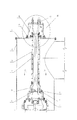
- FIG. 1 is the structural representation view of a cable wire outlet device of an submersible electrical pump in the prior art.
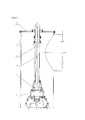
- FIG. 2 is a structural representation view of the dry-type cable wire outlet device of the submersible electrical pump according to the present utility model.
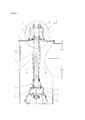
- FIG. 3 is a partially enlarged structural representation view of the portion M in FIG. 2 .
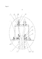
- FIG. 4 is the section structural representation view along the direction A-A in FIG. 2 .
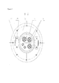
- FIG. 5 is the section structural representation view along the direction B-B in FIG. 2 .
- the cable wire outlet device of the submersible electrical pump in the prior art includes a wire outlet box 5 ′ positioned in the wellbore 2 ′, a cable protection pipe 3 ′ and a cable 4 ′.
- Said wire outlet box 5 ′ is connected to the top of the submersible electrical pump 7 ′, and one end of said cable protection pipe 3 ′ is connected to the top of the wire outlet box 5 ′, and the other end is extended outside the well cover 1 ′ of the wellbore 2 ′.
- Said cable 4 ′ is positioned in the cable protection pipe 3 ′ and connected with the submersible electrical pump 7 ′ through the wire outlet box 5 ′.
- the end of the cable protection pipe is exposed outside, so that the rainwater will enter into the cable protection pipe from its top easily, thus bringing in the potential safe hazard.
- the dry-type cable wire outlet device of an submersible electrical pump includes a wire outlet device 5 positioned in the wellbore 2 , a cable protection pipe 3 and a cable 4 .
- Said wire outlet box 5 is connected to the top of the submersible electrical pump 7 , and one end of said cable protection pipe 3 is connected to the top of the wire outlet box 5 while the other end is extended outside the well cover 1 of the wellbore 2 .
- Said cable 4 is positioned in the cable protection pipe 3 and connected with the submersible electrical pump 7 through the wire outlet box 5 .
- the cable wire outlet device further includes a wire outlet sealing device, which is connected to the well cover 1 . The end of the cable protection pipe 3 extended outside the well cover 1 is positioned in the wire outlet sealing device.
- Said wire outlet sealing device includes a sealing box 11 and a sealing assembly 12 of the wire outlet hole, and said sealing box 11 is connected to the well cover 1 with a sealing ring 10 therein. Said cable 4 passing through the connection of the sealing box 11 is sealed by means of the sealing assembly 12 of the wire outlet hole.
- said sealing ring 10 is the O-type sealing ring sold commercially.
- Said sealing assembly 12 of the wire outlet hole includes a cable sealing ring 121 , a rubber sleeve 122 and a bell mouth 123 having an axial through groove.
- Said cable sealing ring 121 is embedded within the cable wire outlet hole 13 on the sealing box 11 , said rubber sleeve 122 surrounds the cable 4 , and said bell mouth surrounds the rubber sleeve 122 .
- the bell mouth is fastened by means of the anchor ear and the bolt, and one end of the bell mouth 123 is tightly pressing against the cable sealing ring 121 .
- an end of the bell mouth is fastened on the end face of the sealing box 11 by means of the screws, so that the cable sealing ring 121 is tightly pressed within the cable wire outlet hole 13 by the end face of the bell mouth 123 .
- a sealing washer 17 and a sealing platen 16 are provided in said wire outlet sealing device. Said sealing washer 17 is tightly fitted in with the cable protection pipe 3 , and fixed on the well cover 1 by means of the sealing platen 18 .
- Said sealing platen 18 is provided with an anti-lift block 14 connected by bolts 15 .
- An anti-chafe jacket 18 is muff-coupled at the opening of one end of said cable protection pipe 3 , and the end is positioned in the wire outlet sealing device.
- Said cable protection pipe 3 is in Harvard-typed structure and connected by means of screws.
- a drain hole 8 is provided on the side wall at the bottom of said wire outlet box 5 , and a plug 9 is screwed at said drain hole 8 .
- a water-leakage alarm is provided within said wire outlet box 5 and fixed on the top of the submersible electrical pump 7 .
- Said water-leakage alarm is the common water-leakage alarm which is commercially available.
Landscapes
- Engineering & Computer Science (AREA)
- Mechanical Engineering (AREA)
- General Engineering & Computer Science (AREA)
- Architecture (AREA)
- Civil Engineering (AREA)
- Structural Engineering (AREA)
- Structures Of Non-Positive Displacement Pumps (AREA)
Abstract
Description
- The present utility model relates to the field of the hydraulic machinery, especially to a dry-type cable wire outlet device of a submersible electrical pump.
- Presently, the submersible electrical pump is widely utilized increasingly, which is the type of the water pump in which all of the pump body, the impeller and the motor driving the impeller are submerged in water when running. Because the submersible electrical pump is working underwater in a water well while the submersible electrical pump is connected with the control box in control room by means of a cable, a wire outlet device is generally provided outside of the cable, so that it ensures that the cable is not washed by water flow pumped by the submersible electrical pump in work. The wire outlet device in the prior art includes an outlet box, a cable protection pipe and an anti-lift platen, the outlet box is fixedly connected to the top of the submersible electrical pump, a well cover is provided on the top of the water well, and one end of the cable protection pipe is connected to the top of the outlet box while the other end is extended outside the well cover and position stopped by means of the Anti-lift platen.
- However, such a cable wire outlet device of the submersible electrical pump in the prior art has some disadvantages as follow:
- 1) The cable protection pipe is used to protect the cable from being washed by water flow pumped by the water pump, but in practice the pump station with several submersible electrical pump do not need the pump room, that is to say, it is outdoor, so that the rain will easily enter into the cable protection pipe from the opening at the upper end of the cable protection pipe when raining, and thus the cable in the cable protection pipe is easily positioned in the moist environment, which brings in great potential safe hazard for running the submersible electrical pump;
- 2) There is no drain hole at the lower end of the cable protection pipe, so that the rainwater leaked out in the cable protection pipe could not be drained, thus causing the cable to soak in the water for a long time and bringing in the great potential safety hazard to the running of the submersible electrical pump.
- 3) Meanwhile, there is no leaking alarm device provided in the cable protection pipe, so that it is difficult to discover whether water flows into the cable protection pipe, thus the potential safe hazard is difficult to be discovered and excluded in time by the operator over the ground.
- 4) In addition, some wellbores of the submersible electrical pump are very deep, even deep to nearly 30 meters, so that the cable and the cable protection pipe of the submersible electrical pump need to be very long. Although the cable protection pipe generally made of the steel circular pipe could be divided into several segments laterally, those segments of the cable protection pipe are connected with the submersible electrical pump through the cable, which brings in the great inconvenience of assembling, repairing, and disassembling the submersible electrical pump.
- The technical problems being solved by the present utility model is to provide a dry-type cable wire outlet device of a submersible electrical pump with so great seal ability that the safe operation of the submersible electrical pump is ensured. For solving the aforesaid technical problems, the dry-type cable wire outlet device of an submersible electrical pump according to the present utility model includes a wire outlet box positioned in a wellbore, a cable protection pipe and a cable, said wire outlet box is connected to the top of the submersible electrical pump, one end of said cable protection pipe is connected to the top of the wire outlet box, and the other end is extended outside the well cover of the wellbore, said cable is positioned within the cable protection pipe and connected with the submersible electrical pump through the wire outlet box, and the cable wire outlet device further includes a wire outlet sealing device connected to the well cover, and the end of the cable protection pipe which is extended outside the well cover is positioned within the wire outlet sealing device.
- Said wire outlet sealing device includes a sealing box and a sealing assembly of the wire outlet hole, and said sealing box is connected to the well cover with a sealing ring therein; said cable passing through the connection of the sealing box is sealed by means of the sealing assembly of the wire outlet hole.
- Said sealing assembly of the wire outlet hole includes a cable sealing ring, a rubber sleeve and a bell mouth with an axial through groove, said cable sealing ring is embedded in the cable wire outlet hole of the sealing box, said rubber sleeve surrounds the cable, said bell mouth surrounds the rubber sleeve and is fastened by means of an anchor ear and a bolt, and an end of the bell mouth is tightly pressing against the cable sealing ring.
- A sealing washer and a sealing platen is provided within said wire outlet sealing device, and said sealing washer is tightly fitted in with the cable protection pipe and fixed on the well cover by means of the sealing platen.
- An anti-lift block is provided on said sealing platen by means of the bolt.
- The opening of said cable protection pipe, which is positioned in the wire outlet sealing device, is muff-coupled with an anti-chafe jacket.
- Said cable protection pipe is in Harvard-typed structure and connected by screws.
- A drain hole is provided on the side wall at the bottom of said wire outlet box, and a plug is screwed at said drain hole.
- A water-leakage alarm is provided within said wire outlet box and fixed on the top of the submersible electrical pump.
- As compared to the prior art, the present utility model with such construction has several advantages as follow:
- 1) Because a wire sealing device is assembled on the well cover, the opening at the top end of the cable protection pipe is no longer exposed outside, so that the rainwater avoids entering into the cable protection pipe and the cable is kept in the dry environment all the time. Therefore the cable is kept in a dry environment all the time; the device also prevents water flow pumped by the submersible electrical pump from washing on to the cable and prevents rainwater from wetting the cable, thus ensuring the normal, reliable and safe operation of the submersible electrical pump.
- 2) A sealing assembly of the wire outlet hole is positioned at the place where the cable comes out of the wire outlet sealing device, thus ensuring the seal ability of the wire outlet sealing device.
- 3) When the submersible electrical pump is working, the water in the well will be driven upward, which maybe rushes into the place above the cable protection pipe and falls into the cable protection pipe, and thus the sealing washer is tightly fitted in at the top of the cable protection pipe and tightly pressed by means of the sealing platen, which prevents the water in the well from rushing into the cable protection pipe, and ensures the safe operation of the submersible electrical pump.
- 4) Meanwhile, because of a reverse inertia force of the impeller which is generated when stopping the submersible electrical pump, which may cause the water in the well to form an impact force of the recharging which may raise the whole submersible electrical pump and the corresponding connecting pieces. For avoiding this situation, an anti-lift block is provided above the sealing platen so that it prevents the submersible electrical pump from rising.
- 5) In addition, a drain hole and a plug are provided on the side wall at the bottom of the wire outlet box. Even if water is leaked into the wire outlet box and stored therein, water in the wire outlet box could be discharged in time by means of opening the plug when stopping the submersible electrical pump, thus decreasing the effect to the usability of the submersible electrical pump.
- 6) In addition, a water-leakage alarm is assembled within the wire outlet box. The audio-visual alarm will alert the control box of the submersible electrical pump in the control room once water enters into the wire outlet box via the cable protection pipe. Then the administrator in the control room could find that water has entered into the cable protection pipe in time and perform the next operation.
- 7) The cable protection pipe is designed in the Harvard-typed structure, so that the process of the cable passing through the segments of cable protection pipe is omitted, and thus the assembly and disassembling is more convenience and the work efficiency is greatly increased.
- 8) An anti-chafe jacket is muff-coupled at the opening of the cable protection pipe, so that the cable may softly contact with the cable protection pipe made of steel, the friction between the cable and the cable protection pipe is decreased, and the service life of the cable is prolonged.
-
FIG. 1 is the structural representation view of a cable wire outlet device of an submersible electrical pump in the prior art. -
FIG. 2 is a structural representation view of the dry-type cable wire outlet device of the submersible electrical pump according to the present utility model. -
FIG. 3 is a partially enlarged structural representation view of the portion M inFIG. 2 . -
FIG. 4 is the section structural representation view along the direction A-A inFIG. 2 . -
FIG. 5 is the section structural representation view along the direction B-B inFIG. 2 . - Wherein: 1. the well cover; 2. the wellbore; 3. the cable protection pipe; 4. the cable; 5. the wire outlet box; 6. the water-leakage alarm; 7. the submersible electrical pump; 8. the drain hole; 9. the plug; 10. the sealing ring; 11. the sealing box; 12. the sealing assembly of the wire outlet hole; 121. the cable sealing ring; 122. the rubber sleeve; 123. the bell mouth; 13. the cable wire outlet hole; 14. the anti-lift block; 15. the bolt; 16. the sealing platen; 17. the sealing washer; 18. the anti-chafe jacket.
- The present utility model will be further explained by means of the preferred embodiment with reference to the attached figures.
- As shown in
FIG. 1 , the cable wire outlet device of the submersible electrical pump in the prior art includes awire outlet box 5′ positioned in thewellbore 2′, acable protection pipe 3′ and acable 4′. Saidwire outlet box 5′ is connected to the top of the submersibleelectrical pump 7′, and one end of saidcable protection pipe 3′ is connected to the top of thewire outlet box 5′, and the other end is extended outside thewell cover 1′ of thewellbore 2′. Saidcable 4′ is positioned in thecable protection pipe 3′ and connected with the submersibleelectrical pump 7′ through thewire outlet box 5′. In such a cable wire outlet device, the end of the cable protection pipe is exposed outside, so that the rainwater will enter into the cable protection pipe from its top easily, thus bringing in the potential safe hazard. - As the structural representations shown in
FIGS. 2-5 , the dry-type cable wire outlet device of an submersible electrical pump according to the present utility model includes awire outlet device 5 positioned in thewellbore 2, acable protection pipe 3 and acable 4. Saidwire outlet box 5 is connected to the top of the submersibleelectrical pump 7, and one end of saidcable protection pipe 3 is connected to the top of thewire outlet box 5 while the other end is extended outside thewell cover 1 of thewellbore 2. Saidcable 4 is positioned in thecable protection pipe 3 and connected with the submersibleelectrical pump 7 through thewire outlet box 5. The cable wire outlet device further includes a wire outlet sealing device, which is connected to thewell cover 1. The end of thecable protection pipe 3 extended outside thewell cover 1 is positioned in the wire outlet sealing device. - Said wire outlet sealing device includes a
sealing box 11 and a sealingassembly 12 of the wire outlet hole, and said sealingbox 11 is connected to thewell cover 1 with a sealingring 10 therein. Saidcable 4 passing through the connection of thesealing box 11 is sealed by means of the sealingassembly 12 of the wire outlet hole. In this embodiment, said sealingring 10 is the O-type sealing ring sold commercially. - Said sealing
assembly 12 of the wire outlet hole includes acable sealing ring 121, arubber sleeve 122 and abell mouth 123 having an axial through groove. Saidcable sealing ring 121 is embedded within the cablewire outlet hole 13 on thesealing box 11, saidrubber sleeve 122 surrounds thecable 4, and said bell mouth surrounds therubber sleeve 122. The bell mouth is fastened by means of the anchor ear and the bolt, and one end of thebell mouth 123 is tightly pressing against thecable sealing ring 121. In other words, an end of the bell mouth is fastened on the end face of thesealing box 11 by means of the screws, so that thecable sealing ring 121 is tightly pressed within the cablewire outlet hole 13 by the end face of thebell mouth 123. - A sealing
washer 17 and a sealingplaten 16 are provided in said wire outlet sealing device. Said sealingwasher 17 is tightly fitted in with thecable protection pipe 3, and fixed on thewell cover 1 by means of the sealingplaten 18. - Said sealing
platen 18 is provided with ananti-lift block 14 connected bybolts 15. Ananti-chafe jacket 18 is muff-coupled at the opening of one end of saidcable protection pipe 3, and the end is positioned in the wire outlet sealing device. - Said
cable protection pipe 3 is in Harvard-typed structure and connected by means of screws. - A
drain hole 8 is provided on the side wall at the bottom of saidwire outlet box 5, and aplug 9 is screwed at saiddrain hole 8. - A water-leakage alarm is provided within said
wire outlet box 5 and fixed on the top of the submersibleelectrical pump 7. Said water-leakage alarm is the common water-leakage alarm which is commercially available.
Claims (9)
Applications Claiming Priority (4)
| Application Number | Priority Date | Filing Date | Title |
|---|---|---|---|
| CN201010278428 | 2010-09-07 | ||
| CN201010278428A CN101936302B (en) | 2010-09-07 | 2010-09-07 | Cable dry-type line-outgoing device of electric diving pump |
| CN201010278428.4 | 2010-09-07 | ||
| PCT/CN2011/079331 WO2012031543A1 (en) | 2010-09-07 | 2011-09-05 | Dry-type cable wire outlet device for a submersible electrical pump |
Related Parent Applications (1)
| Application Number | Title | Priority Date | Filing Date |
|---|---|---|---|
| PCT/CN2011/079331 Continuation WO2012031543A1 (en) | 2010-09-07 | 2011-09-05 | Dry-type cable wire outlet device for a submersible electrical pump |
Publications (2)
| Publication Number | Publication Date |
|---|---|
| US20130177458A1 true US20130177458A1 (en) | 2013-07-11 |
| US9816508B2 US9816508B2 (en) | 2017-11-14 |
Family
ID=43389812
Family Applications (1)
| Application Number | Title | Priority Date | Filing Date |
|---|---|---|---|
| US13/786,648 Expired - Fee Related US9816508B2 (en) | 2010-09-07 | 2013-03-06 | Dry-type cable wire outlet device for a submersible electrical pump |
Country Status (3)
| Country | Link |
|---|---|
| US (1) | US9816508B2 (en) |
| CN (1) | CN101936302B (en) |
| WO (1) | WO2012031543A1 (en) |
Cited By (4)
| Publication number | Priority date | Publication date | Assignee | Title |
|---|---|---|---|---|
| JP2013217299A (en) * | 2012-04-10 | 2013-10-24 | Ebara Corp | Pump device having rectification cover, and rectification cover |
| US20160318464A1 (en) * | 2015-04-30 | 2016-11-03 | Sumitomo Wiring Systems, Ltd. | Grommet bracket |
| CN106989031A (en) * | 2017-05-23 | 2017-07-28 | 六安海泉泵业有限公司 | A kind of novel submersible pollution discharge pump |
| US11177639B1 (en) * | 2020-05-13 | 2021-11-16 | GAF Energy LLC | Electrical cable passthrough for photovoltaic systems |
Families Citing this family (11)
| Publication number | Priority date | Publication date | Assignee | Title |
|---|---|---|---|---|
| CN101936302B (en) * | 2010-09-07 | 2012-10-10 | 宁波巨神制泵实业有限公司 | Cable dry-type line-outgoing device of electric diving pump |
| CN103291662B (en) * | 2013-05-27 | 2015-12-23 | 黄河水利职业技术学院 | A kind of method that quick nursing maintenance water pump takes out and device |
| CN106555763B (en) * | 2015-09-30 | 2019-08-02 | 浙江三花汽车零部件有限公司 | electric drive pump |
| CN107701489A (en) * | 2017-09-11 | 2018-02-16 | 合肥恒大江海泵业股份有限公司 | A kind of anti-lift device when being used for big-and-middle-sized submerged axial-flow pump operation |
| CN108566027A (en) * | 2018-04-23 | 2018-09-21 | 汉能(天津)工业泵有限公司 | A kind of motor incoming seal protection mechanism |
| CN108825524B (en) * | 2018-08-21 | 2023-12-01 | 合肥新沪屏蔽泵有限公司 | Controller of deep well submersible pump |
| CN111237205B (en) * | 2020-03-25 | 2025-03-21 | 合肥恒大江海泵业股份有限公司 | A combined device for protecting cables and preventing the unit from lifting for a submersible electric pump |
| DE102020004934A1 (en) * | 2020-08-13 | 2022-02-17 | Auto-Kabel Management Gmbh | Gasket for an electric cable |
| CN113613436B (en) * | 2021-08-09 | 2023-04-28 | 深蓝探索动力科技无锡有限公司 | Explosion-proof whole car controller |
| CN118257733B (en) * | 2024-05-31 | 2024-08-06 | 浙江丰球克瑞泵业有限公司 | High-pressure submersible pump installation system and installation method thereof |
| CN120906840B (en) * | 2025-09-30 | 2025-12-30 | 浙江紫荆花泵业有限公司 | Float submersible pump |
Citations (8)
| Publication number | Priority date | Publication date | Assignee | Title |
|---|---|---|---|---|
| US2986308A (en) * | 1958-01-13 | 1961-05-30 | Gilbert & Barker Mfg Co | Submersible pump mounting apparatus |
| US3746472A (en) * | 1971-08-06 | 1973-07-17 | Rupp Co Warren | Submersible electric pump having fluid pressure protective means |
| US3853182A (en) * | 1973-11-26 | 1974-12-10 | Continental Oil Co | Launch tube for a long hole drilling apparatus |
| US4708201A (en) * | 1984-10-29 | 1987-11-24 | Reed Lehman T | Top entry electrical transmission assembly for submersible pumping |
| US5070940A (en) * | 1990-08-06 | 1991-12-10 | Camco, Incorporated | Apparatus for deploying and energizing submergible electric motor downhole |
| US5918268A (en) * | 1995-07-07 | 1999-06-29 | Intelligent Controls, Inc. | Line leak detection |
| US20060151179A1 (en) * | 2002-10-10 | 2006-07-13 | Varco I/P, Inc. | Apparatus and method for transmitting a signal in a wellbore |
| US20070170407A1 (en) * | 2006-01-26 | 2007-07-26 | Yuhuan Top Sun Machinery Tool Co., Ltd. | Goods fastening apparatus with improved structures |
Family Cites Families (11)
| Publication number | Priority date | Publication date | Assignee | Title |
|---|---|---|---|---|
| US3876120A (en) * | 1974-01-14 | 1975-04-08 | Itt | Pumping system and method |
| JP2627763B2 (en) * | 1988-02-29 | 1997-07-09 | 株式会社クボタ | Submersible pump cable drawer fixing structure |
| JP3642578B2 (en) * | 1993-03-30 | 2005-04-27 | 株式会社荏原製作所 | Pump device |
| JP4592354B2 (en) * | 2004-08-23 | 2010-12-01 | 株式会社鶴見製作所 | Water level detection unit for submersible pumps |
| CN2886141Y (en) * | 2005-11-30 | 2007-04-04 | 江苏大学 | Submerged shielding pump |
| CN200946598Y (en) * | 2006-09-08 | 2007-09-12 | 上海连成(集团)有限公司 | Rise-resistant device for preventing submersible pump rising |
| CN201144884Y (en) * | 2007-08-21 | 2008-11-05 | 宁波巨神制泵实业有限公司 | Large submersible pump anti-lift device |
| CN101408205A (en) * | 2008-09-29 | 2009-04-15 | 长沙电机厂有限责任公司 | Anti-lifting machine capable of removing leakage liquid |
| CN101424274A (en) * | 2008-12-10 | 2009-05-06 | 潘述怀 | Mining flame-proof type submersible sand discharging pump |
| CN101936302B (en) * | 2010-09-07 | 2012-10-10 | 宁波巨神制泵实业有限公司 | Cable dry-type line-outgoing device of electric diving pump |
| CN201771824U (en) * | 2010-09-07 | 2011-03-23 | 宁波巨神制泵实业有限公司 | Cable dry outlet device for submersible pump |
-
2010
- 2010-09-07 CN CN201010278428A patent/CN101936302B/en not_active Expired - Fee Related
-
2011
- 2011-09-05 WO PCT/CN2011/079331 patent/WO2012031543A1/en not_active Ceased
-
2013
- 2013-03-06 US US13/786,648 patent/US9816508B2/en not_active Expired - Fee Related
Patent Citations (8)
| Publication number | Priority date | Publication date | Assignee | Title |
|---|---|---|---|---|
| US2986308A (en) * | 1958-01-13 | 1961-05-30 | Gilbert & Barker Mfg Co | Submersible pump mounting apparatus |
| US3746472A (en) * | 1971-08-06 | 1973-07-17 | Rupp Co Warren | Submersible electric pump having fluid pressure protective means |
| US3853182A (en) * | 1973-11-26 | 1974-12-10 | Continental Oil Co | Launch tube for a long hole drilling apparatus |
| US4708201A (en) * | 1984-10-29 | 1987-11-24 | Reed Lehman T | Top entry electrical transmission assembly for submersible pumping |
| US5070940A (en) * | 1990-08-06 | 1991-12-10 | Camco, Incorporated | Apparatus for deploying and energizing submergible electric motor downhole |
| US5918268A (en) * | 1995-07-07 | 1999-06-29 | Intelligent Controls, Inc. | Line leak detection |
| US20060151179A1 (en) * | 2002-10-10 | 2006-07-13 | Varco I/P, Inc. | Apparatus and method for transmitting a signal in a wellbore |
| US20070170407A1 (en) * | 2006-01-26 | 2007-07-26 | Yuhuan Top Sun Machinery Tool Co., Ltd. | Goods fastening apparatus with improved structures |
Cited By (5)
| Publication number | Priority date | Publication date | Assignee | Title |
|---|---|---|---|---|
| JP2013217299A (en) * | 2012-04-10 | 2013-10-24 | Ebara Corp | Pump device having rectification cover, and rectification cover |
| US20160318464A1 (en) * | 2015-04-30 | 2016-11-03 | Sumitomo Wiring Systems, Ltd. | Grommet bracket |
| CN106989031A (en) * | 2017-05-23 | 2017-07-28 | 六安海泉泵业有限公司 | A kind of novel submersible pollution discharge pump |
| US11177639B1 (en) * | 2020-05-13 | 2021-11-16 | GAF Energy LLC | Electrical cable passthrough for photovoltaic systems |
| US11658470B2 (en) | 2020-05-13 | 2023-05-23 | GAF Energy LLC | Electrical cable passthrough |
Also Published As
| Publication number | Publication date |
|---|---|
| WO2012031543A1 (en) | 2012-03-15 |
| US9816508B2 (en) | 2017-11-14 |
| CN101936302B (en) | 2012-10-10 |
| CN101936302A (en) | 2011-01-05 |
Similar Documents
| Publication | Publication Date | Title |
|---|---|---|
| US9816508B2 (en) | Dry-type cable wire outlet device for a submersible electrical pump | |
| CN201771824U (en) | Cable dry outlet device for submersible pump | |
| KR102821242B1 (en) | Underwater pump with cable separation cover with detachable cable protection structure and detachable watertight structure | |
| KR200439970Y1 (en) | Fire Engine Pump | |
| CN206129636U (en) | Submersible electric pump | |
| CN203770188U (en) | Submersible pump base | |
| KR102501938B1 (en) | Underwater pump with cable sealing device for easy installation and lifting | |
| CN204061216U (en) | A kind of submersible pump | |
| CN101705803A (en) | Well-flushing oil-drainage device of oil pumping pipe column | |
| CN116892525A (en) | An environmentally friendly polymer alloy sewage pump and its use method | |
| CN213176274U (en) | A monitoring short pipe with pressure monitoring function | |
| CN210343815U (en) | Flexible shaft transmission type deep well submersible pump with multiple water outlets | |
| CN109972642B (en) | Bucket-type structure drainage device and installation method | |
| CN2059466U (en) | Multifunctional electric immersible pump | |
| CN201185331Y (en) | Apparatus for fixing and protecting cable of submerged pump | |
| CN207864184U (en) | It is a kind of it is portable can low water level use hydraulic-driven immersible pump | |
| CN223853715U (en) | An electric switching valve for roof siphon drainage failure | |
| CN221423532U (en) | Sealing structure for guide vane of submersible pump | |
| KR102501939B1 (en) | Underwater pump with turbulence and vortex protection device in the casing discharge | |
| CN104283362A (en) | Sealing connecting structure for submersible motor and submersible motor with sealing connecting structure | |
| CN212508967U (en) | Automatic directional rotatory water pump impeller assembly device | |
| CN204424572U (en) | A kind of anti-trickle socket | |
| CN223626138U (en) | Waterproof control box for underground parking spot lock | |
| CN214092121U (en) | Guide vane electrode protection device of mixed-flow water turbine | |
| CN211009154U (en) | Submersible electric pump mounting system with anti-lifting machine, anti-reverse rotation and flow guide device |
Legal Events
| Date | Code | Title | Description |
|---|---|---|---|
| AS | Assignment |
Owner name: NINGBO JUSHEN PUMPS INDUSTRY CO., LTD., CHINA Free format text: ASSIGNMENT OF ASSIGNORS INTEREST;ASSIGNORS:YING, JIANGUO;ZHAI, SONGMAO;LI, QUANMIN;REEL/FRAME:030637/0669 Effective date: 20130518 |
|
| STCF | Information on status: patent grant |
Free format text: PATENTED CASE |
|
| FEPP | Fee payment procedure |
Free format text: MAINTENANCE FEE REMINDER MAILED (ORIGINAL EVENT CODE: REM.); ENTITY STATUS OF PATENT OWNER: LARGE ENTITY |
|
| LAPS | Lapse for failure to pay maintenance fees |
Free format text: PATENT EXPIRED FOR FAILURE TO PAY MAINTENANCE FEES (ORIGINAL EVENT CODE: EXP.); ENTITY STATUS OF PATENT OWNER: LARGE ENTITY |
|
| STCH | Information on status: patent discontinuation |
Free format text: PATENT EXPIRED DUE TO NONPAYMENT OF MAINTENANCE FEES UNDER 37 CFR 1.362 |
|
| FP | Lapsed due to failure to pay maintenance fee |
Effective date: 20211114 |