US2012425A - Control system - Google Patents
Control system Download PDFInfo
- Publication number
- US2012425A US2012425A US718093A US71809334A US2012425A US 2012425 A US2012425 A US 2012425A US 718093 A US718093 A US 718093A US 71809334 A US71809334 A US 71809334A US 2012425 A US2012425 A US 2012425A
- Authority
- US
- United States
- Prior art keywords
- power
- relay
- controlling
- power unit
- throttle
- Prior art date
- Legal status (The legal status is an assumption and is not a legal conclusion. Google has not performed a legal analysis and makes no representation as to the accuracy of the status listed.)
- Expired - Lifetime
Links
Images
Classifications
-
- B—PERFORMING OPERATIONS; TRANSPORTING
- B60—VEHICLES IN GENERAL
- B60L—PROPULSION OF ELECTRICALLY-PROPELLED VEHICLES; SUPPLYING ELECTRIC POWER FOR AUXILIARY EQUIPMENT OF ELECTRICALLY-PROPELLED VEHICLES; ELECTRODYNAMIC BRAKE SYSTEMS FOR VEHICLES IN GENERAL; MAGNETIC SUSPENSION OR LEVITATION FOR VEHICLES; MONITORING OPERATING VARIABLES OF ELECTRICALLY-PROPELLED VEHICLES; ELECTRIC SAFETY DEVICES FOR ELECTRICALLY-PROPELLED VEHICLES
- B60L50/00—Electric propulsion with power supplied within the vehicle
- B60L50/10—Electric propulsion with power supplied within the vehicle using propulsion power supplied by engine-driven generators, e.g. generators driven by combustion engines
- B60L50/15—Electric propulsion with power supplied within the vehicle using propulsion power supplied by engine-driven generators, e.g. generators driven by combustion engines with additional electric power supply
-
- B—PERFORMING OPERATIONS; TRANSPORTING
- B60—VEHICLES IN GENERAL
- B60L—PROPULSION OF ELECTRICALLY-PROPELLED VEHICLES; SUPPLYING ELECTRIC POWER FOR AUXILIARY EQUIPMENT OF ELECTRICALLY-PROPELLED VEHICLES; ELECTRODYNAMIC BRAKE SYSTEMS FOR VEHICLES IN GENERAL; MAGNETIC SUSPENSION OR LEVITATION FOR VEHICLES; MONITORING OPERATING VARIABLES OF ELECTRICALLY-PROPELLED VEHICLES; ELECTRIC SAFETY DEVICES FOR ELECTRICALLY-PROPELLED VEHICLES
- B60L2200/00—Type of vehicles
- B60L2200/26—Rail vehicles
-
- Y—GENERAL TAGGING OF NEW TECHNOLOGICAL DEVELOPMENTS; GENERAL TAGGING OF CROSS-SECTIONAL TECHNOLOGIES SPANNING OVER SEVERAL SECTIONS OF THE IPC; TECHNICAL SUBJECTS COVERED BY FORMER USPC CROSS-REFERENCE ART COLLECTIONS [XRACs] AND DIGESTS
- Y02—TECHNOLOGIES OR APPLICATIONS FOR MITIGATION OR ADAPTATION AGAINST CLIMATE CHANGE
- Y02T—CLIMATE CHANGE MITIGATION TECHNOLOGIES RELATED TO TRANSPORTATION
- Y02T10/00—Road transport of goods or passengers
- Y02T10/60—Other road transportation technologies with climate change mitigation effect
- Y02T10/7072—Electromobility specific charging systems or methods for batteries, ultracapacitors, supercapacitors or double-layer capacitors
Definitions
- My invention relates, generally, to control systems and more particularly, to systems for controlling the operation of self-propelled locomotives or other vehicles,
- An object of my invention is to provide a system for controlling the operation of self-propelled vehicles which shall be simple and eflicient in operation and which may be economically manufactured and installed.
- a more specific object of my invention is to provide for automatically controlling the operation of the power units of a self-propelled vehicle in accordance with the load thereon.
- a further object of my invention is to cause certain of the power units of a self-propelled vehicle to develop power only when the load thereon exceeds a predetermined amount.
- a relay which is responsive to the load on the power units of a self-propelled locomotive having a plurality of power units is so connected in the power system that one or more of the units is caused to develop power when the load on the other unit or units increases to a predetermined value, and is caused to run at idling speed, or be completely shut down, when the load decreases to a predetermined value.
- the power unit Ill comprises an internal-combustion engine H, which drives a generator I2.
- the generator 12 supplies current for operating a motor 13, which may be of a type suitable for propell5 ling the locomotive.
- the motor I3 is provided with an armature winding l4 and a series field winding It.
- the generator I2 is provided with an armature winding I6 and a field winding II, which may be excited from a battery It.
- the field current may be controlled by means of a variable rheostat l2, connected in the field-winding circuit.
- the power unit 20 comprises an engine 2
- the motor 23 is provided with an armature winding 24 and a series field winding 25.
- the generator 22 is provided with an armature winding 26 and a field winding 21, which is also elicited from the battery It through a rheostat 29.
- is controlled by electro-pneumatic throttle-actuating mechanisms 30 and 40, respectively, which may be of the type described in United States Patent No. 1,795,896, issued March 10, 1931, to Samuel B. Schenck, and assigned to the Westinghouse Electric & Manufacturing Company.
- the mechanism 30 consists of a linkage 3i, disposed to operate a throttle 32 to control the fuel supplied to the engine I I.
- is actuated 45 step-by-step by three pistons disposed in air cylinders 33, 34 and 35.
- the admission of air to the cylinders 23, I4 and 25 is controlled by electromagnetically operated valves 36, 31 and 38, respectively.
- the air for operating the pistons may be supplied from an air reservoir 39, which may be fed from any suitable source of compressed air, such as an air compressor (not shown).
- the mechanism 40 is similar to the mechanism 38 and consists of a linkage 4
- a manually operable controller .49 is provided for controlling the energizationof "the magnet valves 36, 31 and 38 of the throttle-actuating mechanism 30 in sequential relation, thereby causing the throttle 32 to be operated step-bystep in a manner fully described in the "aforementioned patent to Schenck.
- the .controller 49 also controls the energization of themagnet valves 46, 4'1 and 48 and the -operation'of the throttle 42 under predetermined conditions of load, as will be more fully describedhereinafter.
- and52,'which are controlled by the controller 49, are provided for connecting the generators l2 and 22 to the motors I3 and "23, respectively.
- the generator "22 is connected to the motor 23 to furnish power for-propelling the locomotiveorily when the load on the generator I2 and the motor '13 exceeds a predetermined value.
- 'a relay "53 is "provided "for controlling the operational? the throttle-actuating mechanism 40 and the'swltc'h 52,thereby'controlling the operation of 'the'engine 2
- the relay 53 maybe of anytype which will be responsive to the load imposed on "the locomotive.
- the relay 53* is-provided-with two currentucoils 54 and '55, the coil 54 is connected in series-circuit relation-with the generator l2 and the motor 13, and the coil "55 is connected in series-circuit relation with 'the generator 22 and the motor 23.
- the relay 53 is also-provided with a stabilizing shunt coil 515 which 'is connected across the battery IS.
- the three 'coils 54, 55 and 56 are so connected thatpwhen energized, they produce magnetic forces which act in the same direction to close the contact members of the relay.
- An additional shunt coil “51 is also provided on the relay'wliich opposes the actionof the other three coils.
- the coil 5'! is connected across the battery I'8 "Whenthe switch 52 is closed to connect the motor 23 to the'generator 22, or, in other words, when the power unit 28 is brought into operation.
- the relay 53 is provided with contact members 58 which are so 'connec'ted'in thecontrol-system that the actuating coils-of the 'magnet'valves 46, 47 and "48, and also the switch52 are-energized when the contactmembers 58 are closed'thereby operating the throttle-actuating mechanism 40 to open the throttle 42 o'f "the engine 2
- the relay which is responsive to the load on the locomotive, controls the operation of the power'unit 20.
- the motor 23 is not connected to the generator 22 and the engine-'21 operates-atidling speed.
- the relay 53 will be actuated to cause the switch 52 to close and the throttle-actuating mechanism 40 to open the throttle 42 thereby increasing the speed of the engine 2
- .motor [3 may be connected to the generator
- the controller '49 Whenthe controller '49 is actuated to position a, the'actuating coil of-the magnet valve 38 is also energized through a circuit which extends from a contact member H, which engages the contact-segment, through conductor 12, the actuating coil '13 of the magnet valve 38 and conductors 58 and 6'9 to the negative terminal of the battery
- the throttle 32 is opened one notch when the coil 13 of the magnet valve 38 is energized, thereby increasing the supply of "fuel to the-engine l l and speeding up the engine.
- the throttle 32 may be opened further by moving the controller 49 to position b to energize the actuating coil '14 of the magnet valve 36 through a circuit which extends from-a contact finger 1 5, which engages the contact segment, through conductor 76, the coil 14 and conductors 68 and 69 tothe negative terminal of the battery 8.
- the speed of the engine may be still further increased by actuating the controller 49 to position 0 to'energize the coil 11 of the magnet valve 31.
- the coil 13 of the magnet valve 38 is deenergized when the controller 49 is moved to position cto energize the coil ll of the magnet valve 31, in accordance with the method of operation of the throttle-actuating mechanism described'in the above-noted patent to Schenck.
- the maximum'speed of the engine is obtained by moving the controller 49 to position at to again-energize the coil'l3 of the magnet valve 38, thereby-actuating the throttle 32 to its maximum opening.
- the relay '53 is raised to its uppermost position by the combined action of the coils 5'4 and 56, thereby closing the contact membersf58'o'f'the relay 53.
- the actuating coil of the switch 52 is energized when the contact members of the relay 53 are closed.
- the energizing circuit may be traced from a contact finger 8 I which engages the contact segment 88, through conductor 82, the actuating coil of the switch 52, conductor 88, contact members 58 of the relay 58, and conductors as and 69' to the'negative terminal of the battery l8.
- the closing of the switch 52 connects the motor 28 to the generator 22 through the contact members 84 of the switch 52, and also connects the coil 51 of the relay 58 across the battery l8 through a circuit which extends from conductor 82, through conductor 85, contact members 88 of the switch 52, conductor 81, the coil 51, and conductors 88, 68 and 69 to the negative terminal of the battery l8.
- the coil 51 is so disposed on the relay 58 that it opposes the action of the other shunt coil 58 and the series coils 54 and 55.
- the relay may be caused to respond to the load currents in the motors l8 and 28 without any hunting action, the function of the coils 58 and 51 being to reduce the "hunting" action and to permit adjustments for desired pullin" and drop-ou "values of the relay.
- the throttleactuating mechanism 49 When the contact members 58 of the relay 58 are closed, the actuating coils 9 I, 92 and 98 of the respective magnet valves 45, 41 and 48 are energized through conductors 94, 95 and 98, respectively, in accordance with the position of the controller 49. It will thus be seen that the throttleactuating mechanism 49 will be operated to a position corresponding to that oi the throttle mechanism 89, thereby causing the engine 2
- may be simultaneously controlled by means of the controller 49 in the manner previously described, the speed of both engines being decreased or increased by operating the control drum of the controller to the position corresponding to the desired speed.
- the relay When the load on the locomotive, and consequently the current in the coils 54 and 55 of the relay 58, decreases to a predetermined value, the relay will drop to its lowermost position, thereby denergizing the actuating coils of the switch 52 and the magnet valves of the throttle mechanism 40, which disconnects the motor 28 from the generator 22 and reduces the speed of the engine 21 to its idling speed, or the engine 2
- the engine I I will continue to operate at a speed corresponding to the position of the controller 49, the operation of the relay 58 in no way affecting the control of the power unit ID. If it is desired to stop the locomotive and reduce both engines to their idling speeds, the controller 49 may be moved to the 01! position, as shown in the drawing.
- a control system in combination, a power unit for propelling a vehicle, means for controlling the power developed by the power unit, a second power unit, means for controlling the power developed by the second unit, a common control means for controlling the setting of both of said power controlling means, and means responsive to the load on the first power unit and cooperating with the common control means to control the operation of the second unit.
- a control system in combination, a power unit for propelling a vehicle, means for controlling the power developed by the power unit, a second power unit, means for controlling the power developed by the second unit, a common control means for controlling the position of both of said power controlling means and relay means responsive to the load on the first power unit and cooperating with the common control means to control the operation of the power controlling means for the second power unit.
- a control system in combination, a power unit for propelling a vehicle, means for controlling the iuel supplied to the power unit to control the power developed by the unit, a second power unit, means for controlling the fuel supplied to the second power unit, a controller for controlling the operation of the fuel controlling means, and relay means responsive to the load on the first power unit and cooperating with the controller to control the operation of the second power unit.
- a power unit comprising an internal-combustion engine, a generator and a motor for propelling the locomotive, a throttle-actuating mechanism for controlling the fuel supplied to the engine, a second power unit similar to the first unit, a throttleactuating mechanism for controlling the fuel supplied to the second unit, a controller for controlling the operation of both of said throttleactuating mechanisms, and means responsive to the load on the first power unit and cooperating with the controller to control the operation of the second power unit.
- each unit comprising a motor, a generator and an internal-combustion engine, a throttle-actuating mechanism for controlling the fuel supplied to each engine, control means for controlling the operation of the throttle-actuating mechanisms, and means responsive to the load on one of the power units and cooperating with said control means to control the operation of the other unit.
- each unit comprising a motor, a generator and an internal-combustion engine, a throttle-actuating mechanism for controlling the fuel supplied to each engine, a controller for controlling the operation of both throttle-actuating mechanisms, and relay means responsive to the current traversing the motor of one power unit and cooperating with the controller to control the operation of the other unit.
- a power unit for normally propelling the locomotive, a second power unit, eachunit comprising a motor, a generator and an internalcombustion engine for driving the generator, a throttle-actuating mechanism for controlling the fuel suppliedtoeachengine, a controller for controlling the operation of the throttle-actuating mechanisms, and a relay having an actuating coil energized by the load current in each of the motors and cooperating with the controller to control the operation of the second power unit.
Landscapes
- Engineering & Computer Science (AREA)
- Power Engineering (AREA)
- Transportation (AREA)
- Mechanical Engineering (AREA)
- Control Of Vehicle Engines Or Engines For Specific Uses (AREA)
Description
Aug. 27, 1935.
R. W. GEMMELL CONTROL SYSTEM Filed March 29, 1934 w i W h u i srswm L? o w o n an mm: #5 Wm Mm m 2 M i ww J J NW\ Q 3 k & mm Q 3 Q mm 1 N \m I Q? Gum QM. Nw Mm Patented Aug. 27, 1935 UNITED STATES PATENT OFFICE Westinghouse Electric & Manuf Company, East Pittsburgh, Pa., a corporation of Pennsylvania Application March 29, 1934, Serial No. 718,093
'iclaims.
My invention relates, generally, to control systems and more particularly, to systems for controlling the operation of self-propelled locomotives or other vehicles,
f In order to perform certain kinds of work, as,
for example, switching operations, it may be desirable to equip self-propelled locomotives, or other vehicles, of the gas or Diesel-electric type, with two complete and independent power units, each of which includes an internal-combustion engine, a generator and one or more propelling motors. One of the power units may have sufficient capacity to propel the locomotive and haul light loads, thereby making it necessary to utilize the other unit only for hauling heavy loads. Considerable fuel and also wear on the mechanical parts of the power units may be saved by utilizing the second power unit only when the load on the locomotive is above the normal capacity of the first power unit.
An object of my invention, generally stated, is to provide a system for controlling the operation of self-propelled vehicles which shall be simple and eflicient in operation and which may be economically manufactured and installed.
A more specific object of my invention is to provide for automatically controlling the operation of the power units of a self-propelled vehicle in accordance with the load thereon.
A further object of my invention is to cause certain of the power units of a self-propelled vehicle to develop power only when the load thereon exceeds a predetermined amount.
Other objects of my invention will be either explained fully hereinafter, or will be apparen to those skilled in the art.
In accordance with one embodiment of my invention, a relay which is responsive to the load on the power units of a self-propelled locomotive having a plurality of power units is so connected in the power system that one or more of the units is caused to develop power when the load on the other unit or units increases to a predetermined value, and is caused to run at idling speed, or be completely shut down, when the load decreases to a predetermined value.
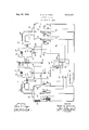
For a fuller understanding of the nature and objects of my invention, reference may be had to the following detailed description, taken in conjunction with the accompanying drawing in which the single figure is a diagrammatic view of a locomotive control system embodying my invention.
Referring to the drawing, I have illustrated a power system having two power units it and 20, 5 suitable for developing power for operating a self-propelled locomotive (not shown). In order to simplify the drawing and the description, I have shown a system having only two power units. However, it will be readily understood that more 10 than two units may be utilized if desired. The power unit Ill comprises an internal-combustion engine H, which drives a generator I2. The generator 12 supplies current for operating a motor 13, which may be of a type suitable for propell5 ling the locomotive. The motor I3 is provided with an armature winding l4 and a series field winding It. The generator I2 is provided with an armature winding I6 and a field winding II, which may be excited from a battery It. The field current may be controlled by means of a variable rheostat l2, connected in the field-winding circuit.
The power unit 20 comprises an engine 2|, a generator 22 and a motor 23, similar to those in the power unit In. The motor 23 is provided with an armature winding 24 and a series field winding 25. The generator 22 is provided with an armature winding 26 and a field winding 21, which is also elicited from the battery It through a rheostat 29.
r The fuel supplied to the engines H and 2| is controlled by electro-pneumatic throttle-actuating mechanisms 30 and 40, respectively, which may be of the type described in United States Patent No. 1,795,896, issued March 10, 1931, to Samuel B. Schenck, and assigned to the Westinghouse Electric & Manufacturing Company.
Inasmuch as the throttle-actuating mechanisms are fully described in the foregoing patent, it is believed to be unnecessary to describe them in detail in this application. Briefly, the mechanism 30 consists of a linkage 3i, disposed to operate a throttle 32 to control the fuel supplied to the engine I I. The linkage 3| is actuated 45 step-by-step by three pistons disposed in air cylinders 33, 34 and 35. The admission of air to the cylinders 23, I4 and 25 is controlled by electromagnetically operated valves 36, 31 and 38, respectively. The air for operating the pistons may be supplied from an air reservoir 39, which may be fed from any suitable source of compressed air, such as an air compressor (not shown).
The mechanism 40 is similar to the mechanism 38 and consists of a linkage 4|, for operating a throttle 42, three air cylinders 43, 44 and 45, and electromagneticaily operated valves 46, 41 and 48 for controlling the admission of air from the reservoir 39 to the air cylinders 43, 44 and 45, respectively.
A manually operable controller .49 is provided for controlling the energizationof "the magnet valves 36, 31 and 38 of the throttle-actuating mechanism 30 in sequential relation, thereby causing the throttle 32 to be operated step-bystep in a manner fully described in the "aforementioned patent to Schenck. The .controller 49 also controls the energization of themagnet valves 46, 4'1 and 48 and the -operation'of the throttle 42 under predetermined conditions of load, as will be more fully describedhereinafter.
Electrically operated switches "5| and52,'which are controlled by the controller 49, are provided for connecting the generators l2 and 22 to the motors I3 and "23, respectively. As willbe described hereinafter, the generator "22 is connected to the motor 23 to furnish power for-propelling the locomotiveorily when the load on the generator I2 and the motor '13 exceeds a predetermined value.
In order that the operation-of 'thepower unit 20 may be controlled in accordance withthe load on the locomotive, 'a relay "53 is "provided "for controlling the operational? the throttle-actuating mechanism 40 and the'swltc'h 52,thereby'controlling the operation of 'the'engine 2| and the motor23. The relay 53 maybe of anytype which will be responsive to the load imposed on "the locomotive. In the illustrated embodiment of the invention, the relay 53*is-provided-with two currentucoils 54 and '55, the coil 54 is connected in series-circuit relation-with the generator l2 and the motor 13, and the coil "55 is connected in series-circuit relation with 'the generator 22 and the motor 23. The relay 53 is also-provided with a stabilizing shunt coil 515 which 'is connected across the battery IS. The three 'coils 54, 55 and 56 are so connected thatpwhen energized, they produce magnetic forces which act in the same direction to close the contact members of the relay. An additional shunt coil "51 is also provided on the relay'wliich opposes the actionof the other three coils. The coil 5'! is connected across the battery I'8 "Whenthe switch 52 is closed to connect the motor 23 to the'generator 22, or, in other words, when the power unit 28 is brought into operation.
The relay 53 is provided with contact members 58 which are so 'connec'ted'in thecontrol-system that the actuating coils-of the 'magnet'valves 46, 47 and "48, and also the switch52 are-energized when the contactmembers 58 are closed'thereby operating the throttle-actuating mechanism 40 to open the throttle 42 o'f "the engine 2| and closing the switch "52 to connect "the motor 23 to the generator 22.
In this manner, the relay which is responsive to the load on the locomotive, controls the operation of the power'unit 20. As long as 'the load is within the normal capacity of the power unit It], the motor 23 is not connected to the generator 22 and the engine-'21 operates-atidling speed. However, if the current in the coil "54, which is directly proportional to 'the load 'on the power unit In, exceeds a predetermined value, the relay 53 will be actuated to cause the switch 52 to close and the throttle-actuating mechanism 40 to open the throttle 42 thereby increasing the speed of the engine 2| which produces power to assist in propelling the locomotive.
As soon as the load on the loco-motive decreases to a point at which the current in the coils 54 and 55 of the relay 53 is below a predetermined value, the relay will drop to its lowermost position and the power unit 29 will be cut out of service, as hereinafter described in detail.
In .order'that the functioning of the apparatus may be more clearly understood, the operation .of :the system will now be described.
Assuming that the engines H and 2| have been started in a manner well known in the .art-and ,are operating at the idling speed, the
.motor [3 may be connected to the generator |2 to propel the locomotive by actuating the controller 49 to position a, thereby establishing an energizing circuit for the actuating coil of the "switch 5| "to close the contact members 6| of the switch. This circuit may be traced from the positive terminal of the battery l8, through conductors 62 and 63, contact members 64 and 65=bridged by the contact segment 66 of the controller 49, conductor 61, the actuating coil of the switch 5|, and conductors 68 and 69 to the negative terminal of the battery l8.
Whenthe controller '49 is actuated to position a, the'actuating coil of-the magnet valve 38 is also energized through a circuit which extends from a contact member H, which engages the contact-segment, through conductor 12, the actuating coil '13 of the magnet valve 38 and conductors 58 and 6'9 to the negative terminal of the battery |8. As fullydescribed in the foregoing patent to Schenck, the throttle 32 is opened one notch when the coil 13 of the magnet valve 38 is energized, thereby increasing the supply of "fuel to the-engine l l and speeding up the engine.
The throttle 32 may be opened further by moving the controller 49 to position b to energize the actuating coil '14 of the magnet valve 36 through a circuit which extends from-a contact finger 1 5, which engages the contact segment, through conductor 76, the coil 14 and conductors 68 and 69 tothe negative terminal of the battery 8.
The speed of the engine may be still further increased by actuating the controller 49 to position 0 to'energize the coil 11 of the magnet valve 31. The energizing circuit-maybe traced from a contact finger 18, which engages the contact segment 66, through conductor 79, the coil 11 and conductors 68 and '69 to the battery l8. It will be noted that the coil 13 of the magnet valve 38 is deenergized when the controller 49 is moved to position cto energize the coil ll of the magnet valve 31, in accordance with the method of operation of the throttle-actuating mechanism described'in the above-noted patent to Schenck. The maximum'speed of the engine is obtained by moving the controller 49 to position at to again-energize the coil'l3 of the magnet valve 38, thereby-actuating the throttle 32 to its maximum opening.
In the event that the load on the locomotive exceeds-the normal capacity of the power'unit I'll, in which case the current in the coil 54 will exceed a predetermined value, the relay '53 is raised to its uppermost position by the combined action of the coils 5'4 and 56, thereby closing the contact membersf58'o'f'the relay 53.
As previously stated, the actuating coil of the switch 52 is energized when the contact members of the relay 53 are closed. The energizing circuit may be traced from a contact finger 8 I which engages the contact segment 88, through conductor 82, the actuating coil of the switch 52, conductor 88, contact members 58 of the relay 58, and conductors as and 69' to the'negative terminal of the battery l8.
The closing of the switch 52 connects the motor 28 to the generator 22 through the contact members 84 of the switch 52, and also connects the coil 51 of the relay 58 across the battery l8 through a circuit which extends from conductor 82, through conductor 85, contact members 88 of the switch 52, conductor 81, the coil 51, and conductors 88, 68 and 69 to the negative terminal of the battery l8.
As descrimd hereinbefore, the coil 51 is so disposed on the relay 58 that it opposes the action of the other shunt coil 58 and the series coils 54 and 55. By properly designing the coils on the relay 53, the relay may be caused to respond to the load currents in the motors l8 and 28 without any hunting action, the function of the coils 58 and 51 being to reduce the "hunting" action and to permit adjustments for desired pullin" and drop-ou "values of the relay.
When the contact members 58 of the relay 58 are closed, the actuating coils 9 I, 92 and 98 of the respective magnet valves 45, 41 and 48 are energized through conductors 94, 95 and 98, respectively, in accordance with the position of the controller 49. It will thus be seen that the throttleactuating mechanism 49 will be operated to a position corresponding to that oi the throttle mechanism 89, thereby causing the engine 2| to operate at the same speed as the engine I I, and the power unit to assume the same load, or approximately the same, as the power unit Ill. The two engines II and 2| may be simultaneously controlled by means of the controller 49 in the manner previously described, the speed of both engines being decreased or increased by operating the control drum of the controller to the position corresponding to the desired speed.
When the load on the locomotive, and consequently the current in the coils 54 and 55 of the relay 58, decreases to a predetermined value, the relay will drop to its lowermost position, thereby denergizing the actuating coils of the switch 52 and the magnet valves of the throttle mechanism 40, which disconnects the motor 28 from the generator 22 and reduces the speed of the engine 21 to its idling speed, or the engine 2| may be stopped if desired, in which event it would be again restarted, upon the operation of the relay 53, by cranking the engine 2| from the battery 18, in a manner well known in the art.
However, the engine I I will continue to operate at a speed corresponding to the position of the controller 49, the operation of the relay 58 in no way affecting the control of the power unit ID. If it is desired to stop the locomotive and reduce both engines to their idling speeds, the controller 49 may be moved to the 01! position, as shown in the drawing.
From the foregoing description, it will be apparent that I have provided a system for controlling the operation of a self-propelled vehicle, equipped with two or more complete power units, which will effect a considerable saving in the amount of fuel required to operate the vehicle when it is utilized to perform operations of a certain type. The wear on the mechanical equipment oi-the locomotive is also considerably reduced, since only one power unit is utilized when the locomotive is hauling light loads, the other power unitbelng also utilized only for heavy or peak loads." I
' I do'not desire to be restricted to the specific embodiment of my invention herein shown'and described, since it is evident that it may be changed and modified without departing from the spirit and scope of my invention as defined in the appended claims.
I claim as my invention:
1. In a control system, in combination, a power unit for propelling a vehicle, means for controlling the power developed by the power unit, a second power unit, means for controlling the power developed by the second unit, a common control means for controlling the setting of both of said power controlling means, and means responsive to the load on the first power unit and cooperating with the common control means to control the operation of the second unit.
2. In a control system, in combination, a power unit for propelling a vehicle, means for controlling the power developed by the power unit, a second power unit, means for controlling the power developed by the second unit, a common control means for controlling the position of both of said power controlling means and relay means responsive to the load on the first power unit and cooperating with the common control means to control the operation of the power controlling means for the second power unit.
3. In a control system, in combination, a power unit for propelling a vehicle, means for controlling the iuel supplied to the power unit to control the power developed by the unit, a second power unit, means for controlling the fuel supplied to the second power unit, a controller for controlling the operation of the fuel controlling means, and relay means responsive to the load on the first power unit and cooperating with the controller to control the operation of the second power unit.
4. In a control system, in combination, a power unit comprising an internal-combustion engine, a generator and a motor for propelling the locomotive, a throttle-actuating mechanism for controlling the fuel supplied to the engine, a second power unit similar to the first unit, a throttleactuating mechanism for controlling the fuel supplied to the second unit, a controller for controlling the operation of both of said throttleactuating mechanisms, and means responsive to the load on the first power unit and cooperating with the controller to control the operation of the second power unit.
5. In a control system, in combination, two power units, each unit comprising a motor, a generator and an internal-combustion engine, a throttle-actuating mechanism for controlling the fuel supplied to each engine, control means for controlling the operation of the throttle-actuating mechanisms, and means responsive to the load on one of the power units and cooperating with said control means to control the operation of the other unit.
6. In a control system, in combination, two power units, each unit comprising a motor, a generator and an internal-combustion engine, a throttle-actuating mechanism for controlling the fuel supplied to each engine, a controller for controlling the operation of both throttle-actuating mechanisms, and relay means responsive to the current traversing the motor of one power unit and cooperating with the controller to control the operation of the other unit.
1. In a locomotive control system,tincombination, a power unit for normally propelling the locomotive, a second power unit, eachunit comprising a motor, a generator and an internalcombustion engine for driving the generator, a throttle-actuating mechanism for controlling the fuel suppliedtoeachengine, a controller for controlling the operation of the throttle-actuating mechanisms, and a relay having an actuating coil energized by the load current in each of the motors and cooperating with the controller to control the operation of the second power unit.
ROBERT W. GEMMELL.
Priority Applications (1)
| Application Number | Priority Date | Filing Date | Title |
|---|---|---|---|
| US718093A US2012425A (en) | 1934-03-29 | 1934-03-29 | Control system |
Applications Claiming Priority (1)
| Application Number | Priority Date | Filing Date | Title |
|---|---|---|---|
| US718093A US2012425A (en) | 1934-03-29 | 1934-03-29 | Control system |
Publications (1)
| Publication Number | Publication Date |
|---|---|
| US2012425A true US2012425A (en) | 1935-08-27 |
Family
ID=24884793
Family Applications (1)
| Application Number | Title | Priority Date | Filing Date |
|---|---|---|---|
| US718093A Expired - Lifetime US2012425A (en) | 1934-03-29 | 1934-03-29 | Control system |
Country Status (1)
| Country | Link |
|---|---|
| US (1) | US2012425A (en) |
Cited By (2)
| Publication number | Priority date | Publication date | Assignee | Title |
|---|---|---|---|---|
| US2666872A (en) * | 1950-08-19 | 1954-01-19 | Westinghouse Electric Corp | Electric power system for aircraft |
| US3191050A (en) * | 1961-10-25 | 1965-06-22 | Nordberg Manufacturing Co | Engine generator set |
-
1934
- 1934-03-29 US US718093A patent/US2012425A/en not_active Expired - Lifetime
Cited By (2)
| Publication number | Priority date | Publication date | Assignee | Title |
|---|---|---|---|---|
| US2666872A (en) * | 1950-08-19 | 1954-01-19 | Westinghouse Electric Corp | Electric power system for aircraft |
| US3191050A (en) * | 1961-10-25 | 1965-06-22 | Nordberg Manufacturing Co | Engine generator set |
Similar Documents
| Publication | Publication Date | Title |
|---|---|---|
| US4266485A (en) | Control system for economic operation of multiple locomotive trains | |
| US2419178A (en) | Electric motor control for seriesparallel operation | |
| US2012425A (en) | Control system | |
| US2292203A (en) | Generating electric drive and control system | |
| US2371832A (en) | Diesel electric drive and control system | |
| US1907974A (en) | Control system | |
| US1821827A (en) | Self propelled vehicle | |
| US1833017A (en) | Electric train control for gas engine propulsion | |
| US2195766A (en) | Arrangement for transforming mechanical energy into mechanical energy with intermediate transformation into electrical energy | |
| US2290667A (en) | Power system | |
| US2383813A (en) | Electric motor control system | |
| US2304937A (en) | Generating electric drive and control system | |
| US2318043A (en) | Control system | |
| US2525472A (en) | Turbine-electric locomotive control system | |
| US2098761A (en) | Regulating device for a combustion power engine coupled to an electric generator for vehicles | |
| US2371833A (en) | Generating electric traction and control system | |
| US2175862A (en) | Locomotive control system | |
| US1871472A (en) | Power system | |
| US2428574A (en) | Control system for reducing wheel slippage | |
| US1851725A (en) | Electric power device | |
| US2187781A (en) | Vehicle drive system | |
| US2431145A (en) | Electric motor control system for locomotives | |
| US2433628A (en) | Diesel-electric vehicle with automatic weakening of the fields of the driving motors | |
| US2409740A (en) | Locomotive control system | |
| US1800250A (en) | Air-compressor drive means for gas-electric locomotives |