US20120249805A1 - Image capturing system and image capturing method - Google Patents
Image capturing system and image capturing method Download PDFInfo
- Publication number
- US20120249805A1 US20120249805A1 US13/065,856 US201113065856A US2012249805A1 US 20120249805 A1 US20120249805 A1 US 20120249805A1 US 201113065856 A US201113065856 A US 201113065856A US 2012249805 A1 US2012249805 A1 US 2012249805A1
- Authority
- US
- United States
- Prior art keywords
- image
- amount
- rear blur
- basis
- image capturing
- Prior art date
- Legal status (The legal status is an assumption and is not a legal conclusion. Google has not performed a legal analysis and makes no representation as to the accuracy of the status listed.)
- Granted
Links
Images


Classifications
-
- H—ELECTRICITY
- H04—ELECTRIC COMMUNICATION TECHNIQUE
- H04N—PICTORIAL COMMUNICATION, e.g. TELEVISION
- H04N5/00—Details of television systems
- H04N5/76—Television signal recording
- H04N5/765—Interface circuits between an apparatus for recording and another apparatus
- H04N5/77—Interface circuits between an apparatus for recording and another apparatus between a recording apparatus and a television camera
- H04N5/772—Interface circuits between an apparatus for recording and another apparatus between a recording apparatus and a television camera the recording apparatus and the television camera being placed in the same enclosure
-
- H—ELECTRICITY
- H04—ELECTRIC COMMUNICATION TECHNIQUE
- H04N—PICTORIAL COMMUNICATION, e.g. TELEVISION
- H04N23/00—Cameras or camera modules comprising electronic image sensors; Control thereof
- H04N23/60—Control of cameras or camera modules
- H04N23/68—Control of cameras or camera modules for stable pick-up of the scene, e.g. compensating for camera body vibrations
- H04N23/681—Motion detection
- H04N23/6812—Motion detection based on additional sensors, e.g. acceleration sensors
-
- H—ELECTRICITY
- H04—ELECTRIC COMMUNICATION TECHNIQUE
- H04N—PICTORIAL COMMUNICATION, e.g. TELEVISION
- H04N23/00—Cameras or camera modules comprising electronic image sensors; Control thereof
- H04N23/60—Control of cameras or camera modules
- H04N23/68—Control of cameras or camera modules for stable pick-up of the scene, e.g. compensating for camera body vibrations
- H04N23/682—Vibration or motion blur correction
- H04N23/683—Vibration or motion blur correction performed by a processor, e.g. controlling the readout of an image memory
Definitions
- This invention relates to an image capturing system and an image capturing method.
- JP2006-259688A discloses a camera in which the focus lens is moved at high speed in a case where the shutter key is fully pressed before the focus lens reaches the focus position. Thus, focusing can be performed again before performing image pickup.
- An image capturing system includes: an imaging device on which an image of an object is formed; a front-rear blur amount detection unit that detects a front-rear blur amount occurring during image pickup; and an image processing unit that performs image processing on image data obtained by the imaging device on the basis of the front-rear blur amount.
- An image capturing method includes: obtaining an object image using an imaging device on which an image of an object is formed; detecting a front-rear blur amount occurring during image pickup; and performing image processing on image data obtained by the imaging device on the basis of the front-rear blur amount.
- FIG. 1 is a schematic block diagram of an image capturing system according to a first embodiment.
- FIG. 2 is a flowchart showing control executed during image pickup according to the first embodiment.
- FIG. 3 is a graph showing a relationship between a front-rear blur amount and an image restoration amount.
- FIG. 4 is a flowchart showing control executed during image pickup according to a second embodiment.
- FIG. 5 is a flowchart showing control executed during image pickup according to a third embodiment.
- FIG. 6 is a schematic block diagram of an image capturing system according to a fourth embodiment.
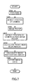
- FIG. 7 is a flowchart showing control executed during image pickup according to the fourth embodiment.
- FIG. 8 is a schematic block diagram of an image capturing system according to a fifth embodiment.
- FIG. 1 is a schematic block diagram of an image capturing system according to the first embodiment.
- a digital still camera to be referred to as a camera hereafter
- an image capturing device to be described as an image capturing device.
- the camera includes an optical system 1 , a blur detection unit 2 , an imaging device 3 , an image processing unit 4 , an image display unit 5 , an image storage unit 6 , and a control unit 7 .
- the optical system 1 is constituted by a plurality of lenses and an aperture, for example. A part of the lenses is moved in an optical axis direction by an actuator or the like. In so doing, focal point adjustment is performed.
- the blur detection unit 2 detects a front-rear blur amount of the camera.
- the front-rear blur amount is an amount (a movement amount from a reference position) of blur in the optical axis direction of the camera during image pickup relative to a reference position of the camera.
- the blur detection unit 2 is an acceleration sensor, a gyro sensor, or a position sensor, for example.
- the reference position is a position of the camera following focusing, for example a position of the camera after focusing has been performed by pressing a release button by a predetermined amount.
- the imaging device 3 outputs an electric signal corresponding to light incident on a light receiving surface at a predetermined timing.
- the imaging device 3 is constituted by a CCD (Charge Coupled Device) sensor or a CMOS (Complementary Metal Oxide Semiconductor) sensor, for example, but may be constituted by various other types of imaging devices.
- the image processing unit 4 includes a restoration amount calculation unit 8 and an image restoration unit 9 .
- the restoration amount calculation unit 8 calculates an image restoration amount for the electric signal output by the imaging device 3 on the basis of the front-rear blur amount detected by the blur detection unit 2 .
- the image restoration unit 9 performs image restoration processing on the electric signal output by the imaging device 3 on the basis of the image restoration amount calculated by the restoration amount calculation unit 8 .
- the image processing unit 4 also performs processing such as white balance adjustment and gradation/level correction. Image data processed by the image processing unit 4 are output to the image display unit 5 and the image storage unit 6 .
- the image processing unit 4 is constituted by a CPU, a ROM, a RAM, and so on.
- the ROM stores a control program and various data.
- the CPU executes calculations on the basis of the control program stored in the ROM such that the respective functions of the image processing unit 4 are exhibited.
- the image display unit 5 is a color liquid crystal display (LCD) panel, an organic EL (OEL) display panel, or the like.
- the image display unit 5 displays a photographed image on the basis of an image signal output by the image processing unit 4 .
- the image storage unit 6 stores the image signal output by the image processing unit 4 as image data.
- the control unit 7 is connected to the blur detection unit 2 , image processing unit 4 , image display unit 5 , and image storage unit 6 , and controls the entire camera, including these units.
- the control unit 7 is constituted by a CPU, a ROM, a RAM, and so on.
- the ROM stores a control program and various data.
- the CPU executes calculations on the basis of the control program stored in the ROM such that the respective functions of the control unit 7 are exhibited.
- a step S 100 When it is determined, in a step S 100 , that the release button has been pressed by a predetermined amount (set in a half pressed state, for example) by a photographer, focal point adjustment is performed by controlling the optical system 1 , and as a result, an object is brought into focus.
- a predetermined amount set in a half pressed state, for example
- a step S 101 the position of the camera following focusing is detected by the blur detection unit 2 , and the reference position is determined.
- the position (attitude) of the camera following focusing is set as the reference position. It should be noted that the step S 100 and the step S 101 may be performed simultaneously.
- step S 102 When it is determined, in a step S 102 , that the release button has been pressed further (set in a fully pressed state, for example) by the photographer, image pickup is performed.
- a step S 103 the position of the camera during image pickup (at the moment of image pickup) is detected by the blur detection unit 2 .
- the position of the camera may deviate in the optical axis direction between focusing and image pickup, and as a result, a front-rear blur may occur. Therefore, the position of the camera during image pickup is detected in the step S 103 .
- a step S 104 the front-rear blur amount is calculated from the position of the camera following focusing and the position of the camera during image pickup. Note that when the front-rear blur amount is zero, a step S 105 is not performed.
- the image restoration amount is calculated on the basis of the calculated front-rear blur amount.
- the image restoration amount is calculated using a graph shown in FIG. 3 , for example.
- the image restoration amount increases as the front-rear blur amount from the reference position increases. It should be noted that in FIG. 3 , the reference position is set at zero, a direction approaching the object from the reference position is set as “+”, and a direction heading away from the object is set as “ ⁇ ”.
- To calculate the image restoration amount means other than the graph, for example an equation corresponding to the graph or an approximation thereof, may be used. Alternatively, a lookup table, for example, may be used.
- a step S 106 image processing for obtaining a restored image on which the effects of the front-rear blur are reduced is performed on the basis of the calculated image restoration amount using a differential equation shown in Equation (1), for example.
- Equation (1) f is the restored image, g is the photographed image, and a1 to an are values determined by image forming characteristics of the optical system, the image restoration amount, and so on.
- the method of subjecting the photographed image to image restoration processing on the basis of the image restoration amount is not limited to the method described above.
- a step S 107 the image subjected to image processing on the basis of the image restoration amount is displayed on the image display unit 5 , and corresponding image data are stored in the image storage unit 6 .
- the front-rear blur amount, the image restoration amount, and so on may be stored in the image processing unit 4 , for example.
- a time required for image processing can be shortened in a case where the release button is pressed continuously in order to photograph continuous images, and as a result, a number of images that can be photographed per unit time can be increased.
- the image restoration processing based on the front-rear blur amount is performed by the image processing unit 4 on the image data obtained when the front-rear blur occurred, and therefore an image on which the effects of the front-rear blur are reduced can be obtained quickly.
- the image photographed at the front-rear blur can be restored to the image following focusing.
- image restoration processing corresponding to the front-rear blur amount can be performed appropriately.
- the second embodiment is configured similarly to the first embodiment.
- the second embodiment differs from the first embodiment in the control executed during image pickup.
- the control executed during image pickup will be described using a flowchart shown in FIG. 4 .
- Control executed from a step S 200 to a step S 205 is identical to the control executed from the step S 100 to the step S 105 of the first embodiment, and therefore description of this control has been omitted.
- the image restoration amount is corrected in accordance with a condition of the optical system 1 .
- the condition of the optical system 1 is information relating, for example, to a focal length.
- the effects of the front-rear blur amount on the photographed image vary depending on whether the focal length of the optical system 1 is on a wide angle side or a telephoto side. Even when the front-rear blur amount remains constant, for example, the effects of the front-rear blur amount are greater on an image photographed on the wide angle side than an image photographed on the telephoto side. Therefore, the image restoration amount is corrected in accordance with the condition of the optical system 1 .
- an accurate image restoration amount can be calculated.
- the image restoration amount is corrected in accordance with a characteristic of the optical system 1 .
- the characteristic of the optical system 1 is information relating, for example, to aberration.
- An image formed on the light receiving surface of the imaging device 3 via the optical system 1 varies in aberration depending on an image height from an optical axis and so on. Therefore, by correcting the image restoration amount on the basis of an MTF and so on, for example, an accurate image restoration amount can be calculated.
- condition of the optical system 1 and the characteristic of the optical system 1 are stored in advance as a lookup table, for example. If the characteristic of the optical system 1 can be represented by an equation, the equation (including an approximation) may also be stored in advance.
- a step S 207 image processing for obtaining a restored image is performed on the basis of the corrected image restoration amount.
- a step S 208 the image subjected to the image processing on the basis of the image restoration amount is displayed on the image display unit 5 , and corresponding image data are stored in the image storage unit 6 .
- the time required for the image processing can be shortened.
- the third embodiment is configured similarly to the first embodiment.
- the third embodiment differs from the second embodiment in the control executed during image pickup.
- the control executed during image pickup will be described using a flowchart shown in FIG. 5 .
- Control executed from a step S 300 to a step S 304 is identical to the control executed from the step S 200 to the step S 204 of the second embodiment, and therefore description of this control has been omitted.
- a step S 305 the front-rear blur amount is compared to an allowable value.
- the image restoration processing is not performed and the routine advances to a step S 309 .
- the routine advances to a step S 306 in order to perform the image restoration processing.
- the allowable value is a preset value at which a user does not perceive a front-rear blur when the image is printed or the like, for example.
- the allowable value is set by a manufacturer during design. Alternatively, the photographer may set the allowable value.
- Control executed from a step S 306 to a step S 308 is identical to the control executed from the step S 206 to the step S 208 of the second embodiment, and therefore description of this control has been omitted.
- a step S 309 when the front-rear blur amount is equal to or smaller than the allowable value, the image photographed by the imaging device 3 is displayed on the image display unit 5 as is, and the corresponding image data are stored in the image storage unit 6 .
- the front-rear blur amount is larger than the allowable value, the image subjected to image restoration in accordance with the front-rear blur amount is displayed on the image display unit 5 , and the corresponding image data are stored in the image storage unit 6 .
- an amount of image processing can be reduced in a case where the front-rear blur amount is substantially non-existent.
- FIG. 6 is a schematic block diagram of the image capturing system according to the fourth embodiment.
- the image capturing system according to the fourth embodiment is constituted by an image capturing device and a processing device.
- a case in which a camera is used as the image capturing device and a computer is used as the processing device will be described.
- this invention is not limited thereto.
- the camera includes the optical system 1 , the imaging device 3 , the blur detection unit 2 , the restoration amount calculation unit 8 , a recording unit 11 , and the control unit 7 .
- Identical constitutions to the first embodiment have been allocated identical reference numerals to the first embodiment, and description thereof has been omitted.
- the recording unit 11 records the electric signal output by the imaging device 3 as image data. Further, the recording unit 11 records the image restoration amount calculated by the restoration amount calculation unit 8 . It should be noted that the image data and the image restoration amount are recorded correlatively.
- the recording unit 11 also stores the image data and the image restoration amount on a storage medium.
- the storage medium is a magnetic disk, a magneto-optical disk, a CD-ROM, a DVD-ROM, a semiconductor memory, or the like, for example.
- the storage medium can be attached to the camera and the computer detachably.
- the computer includes an image processing unit 12 , the image display unit 5 , and the image storage unit 6 .
- the image processing unit 12 includes an image restoration unit 13 .
- the image restoration unit 13 reads the image data and image restoration amount stored on the storage medium and performs image restoration processing on the electric signal output from the imaging device 3 .
- the computer is constituted by a CPU, a ROM, a RAM, and so on.
- the ROM stores a control program and various data.
- the CPU executes calculations on the basis of the control program stored in the ROM such that the respective functions of the processing device are exhibited.
- Control executed from a step S 400 to a step S 405 is identical to the control executed from the step S 100 to the step S 105 of the first embodiment, and therefore description of this control has been omitted.
- a step S 406 the image data and the image restoration amount are stored on the storage medium.
- the image data and image restoration amount stored on the storage medium are read by the personal computer and subjected to the image restoration processing in order to create an image on which the effects of a front-rear blur are reduced.
- the image data and the image restoration amount are stored on the storage medium by the recording unit 11 .
- the image restoration processing is then performed by the computer, and therefore an amount of processing performed in the camera can be reduced.
- FIG. 8 is a schematic block diagram of the fifth embodiment.
- a camera includes, in addition to the constitution of the camera according to the fourth embodiment, a first communication unit 14 . All other constitutions are identical to the fourth embodiment, and therefore description of these constitutions has been omitted.
- the first communication unit 14 reads the image data and the image restoration amount recorded in a recording unit 15 and transmits a signal corresponding to the image data and the image restoration amount wirelessly to a second communication unit 17 of a computer.
- the computer includes the second communication unit 17 , the image processing unit 12 , the image display unit 5 , and the image storage unit 6 .
- the second communication unit 17 receives the signal corresponding to the image data and the image restoration amount transmitted from the first communication unit 14 , and transmits the received signal to the image processing unit 12 .
- the image processing unit 12 creates an image on which the effects of a front-rear blur are reduced on the basis of the image data and the image restoration amount.
- the image data and image restoration amount are transmitted from the first communication unit 14 of the camera to the second communication unit 17 of the computer, and the image processing is performed by the computer in a different location to the camera.
- the restoration amount calculation unit 8 is provided in the camera, but the restoration amount calculation unit 8 may be provided in the computer.
- a storage capacity of the camera can be reduced. Further, the amount of image processing performed in the camera can be reduced. Moreover, the image processing can be performed as needed by the computer, which is disposed in a separate location to the camera.
- the image capturing system may include a CPU, a main storage device such as a RAM, and a non-temporary computer-readable storage medium storing a program for realizing all or a part of the processing described above.
- this program will be referred to as an image processing program.
- the non-temporary computer-readable recording medium is a magnetic disk, a magneto-optical disk, a CD-ROM, a DVD-ROM, a semiconductor memory, or similar.
- the blur detection unit may be provided in a plurality.
- an average value, a maximum value, or a minimum value of detection amounts detected by the plurality of blur detection units may be used as a blur amount.
Landscapes
- Engineering & Computer Science (AREA)
- Multimedia (AREA)
- Signal Processing (AREA)
- Studio Devices (AREA)
Abstract
Description
- This invention relates to an image capturing system and an image capturing method.
- In a conventional camera, a focus lens reaches a focus position when a shutter key is half pressed. JP2006-259688A discloses a camera in which the focus lens is moved at high speed in a case where the shutter key is fully pressed before the focus lens reaches the focus position. Thus, focusing can be performed again before performing image pickup.
- An image capturing system according to an aspect of this invention includes: an imaging device on which an image of an object is formed; a front-rear blur amount detection unit that detects a front-rear blur amount occurring during image pickup; and an image processing unit that performs image processing on image data obtained by the imaging device on the basis of the front-rear blur amount.
- An image capturing method according to another aspect of this invention includes: obtaining an object image using an imaging device on which an image of an object is formed; detecting a front-rear blur amount occurring during image pickup; and performing image processing on image data obtained by the imaging device on the basis of the front-rear blur amount.
-
FIG. 1 is a schematic block diagram of an image capturing system according to a first embodiment. -
FIG. 2 is a flowchart showing control executed during image pickup according to the first embodiment. -
FIG. 3 is a graph showing a relationship between a front-rear blur amount and an image restoration amount. -
FIG. 4 is a flowchart showing control executed during image pickup according to a second embodiment. -
FIG. 5 is a flowchart showing control executed during image pickup according to a third embodiment. -
FIG. 6 is a schematic block diagram of an image capturing system according to a fourth embodiment. -
FIG. 7 is a flowchart showing control executed during image pickup according to the fourth embodiment. -
FIG. 8 is a schematic block diagram of an image capturing system according to a fifth embodiment. - A first embodiment of this invention will be described using
FIG. 1 .FIG. 1 is a schematic block diagram of an image capturing system according to the first embodiment. Here, a digital still camera (to be referred to as a camera hereafter) will be described as an image capturing device. - The camera includes an
optical system 1, ablur detection unit 2, animaging device 3, animage processing unit 4, animage display unit 5, animage storage unit 6, and acontrol unit 7. - The
optical system 1 is constituted by a plurality of lenses and an aperture, for example. A part of the lenses is moved in an optical axis direction by an actuator or the like. In so doing, focal point adjustment is performed. - The
blur detection unit 2 detects a front-rear blur amount of the camera. The front-rear blur amount is an amount (a movement amount from a reference position) of blur in the optical axis direction of the camera during image pickup relative to a reference position of the camera. Theblur detection unit 2 is an acceleration sensor, a gyro sensor, or a position sensor, for example. The reference position is a position of the camera following focusing, for example a position of the camera after focusing has been performed by pressing a release button by a predetermined amount. - The
imaging device 3 outputs an electric signal corresponding to light incident on a light receiving surface at a predetermined timing. Theimaging device 3 is constituted by a CCD (Charge Coupled Device) sensor or a CMOS (Complementary Metal Oxide Semiconductor) sensor, for example, but may be constituted by various other types of imaging devices. - The
image processing unit 4 includes a restorationamount calculation unit 8 and animage restoration unit 9. - The restoration
amount calculation unit 8 calculates an image restoration amount for the electric signal output by theimaging device 3 on the basis of the front-rear blur amount detected by theblur detection unit 2. - The
image restoration unit 9 performs image restoration processing on the electric signal output by theimaging device 3 on the basis of the image restoration amount calculated by the restorationamount calculation unit 8. - The
image processing unit 4 also performs processing such as white balance adjustment and gradation/level correction. Image data processed by theimage processing unit 4 are output to theimage display unit 5 and theimage storage unit 6. - The
image processing unit 4 is constituted by a CPU, a ROM, a RAM, and so on. The ROM stores a control program and various data. The CPU executes calculations on the basis of the control program stored in the ROM such that the respective functions of theimage processing unit 4 are exhibited. - The
image display unit 5 is a color liquid crystal display (LCD) panel, an organic EL (OEL) display panel, or the like. Theimage display unit 5 displays a photographed image on the basis of an image signal output by theimage processing unit 4. - The
image storage unit 6 stores the image signal output by theimage processing unit 4 as image data. - The
control unit 7 is connected to theblur detection unit 2,image processing unit 4,image display unit 5, andimage storage unit 6, and controls the entire camera, including these units. Thecontrol unit 7 is constituted by a CPU, a ROM, a RAM, and so on. The ROM stores a control program and various data. The CPU executes calculations on the basis of the control program stored in the ROM such that the respective functions of thecontrol unit 7 are exhibited. - Next, control executed during image pickup according to this embodiment will be described using a flowchart shown in
FIG. 2 . - When it is determined, in a step S100, that the release button has been pressed by a predetermined amount (set in a half pressed state, for example) by a photographer, focal point adjustment is performed by controlling the
optical system 1, and as a result, an object is brought into focus. - In a step S101, the position of the camera following focusing is detected by the
blur detection unit 2, and the reference position is determined. Here, the position (attitude) of the camera following focusing is set as the reference position. It should be noted that the step S100 and the step S101 may be performed simultaneously. - When it is determined, in a step S102, that the release button has been pressed further (set in a fully pressed state, for example) by the photographer, image pickup is performed.
- In a step S103, the position of the camera during image pickup (at the moment of image pickup) is detected by the
blur detection unit 2. The position of the camera may deviate in the optical axis direction between focusing and image pickup, and as a result, a front-rear blur may occur. Therefore, the position of the camera during image pickup is detected in the step S103. - In a step S104, the front-rear blur amount is calculated from the position of the camera following focusing and the position of the camera during image pickup. Note that when the front-rear blur amount is zero, a step S105 is not performed.
- In the step S105, the image restoration amount is calculated on the basis of the calculated front-rear blur amount. The image restoration amount is calculated using a graph shown in
FIG. 3 , for example. The image restoration amount increases as the front-rear blur amount from the reference position increases. It should be noted that inFIG. 3 , the reference position is set at zero, a direction approaching the object from the reference position is set as “+”, and a direction heading away from the object is set as “−”. - To calculate the image restoration amount, means other than the graph, for example an equation corresponding to the graph or an approximation thereof, may be used. Alternatively, a lookup table, for example, may be used.
- In a step S106, image processing for obtaining a restored image on which the effects of the front-rear blur are reduced is performed on the basis of the calculated image restoration amount using a differential equation shown in Equation (1), for example.
-
f=g+a1×g′+a2×g″+ . . . +an×g′(n) Equation (1) - In Equation (1), f is the restored image, g is the photographed image, and a1 to an are values determined by image forming characteristics of the optical system, the image restoration amount, and so on. The method of subjecting the photographed image to image restoration processing on the basis of the image restoration amount is not limited to the method described above.
- In a step S107, the image subjected to image processing on the basis of the image restoration amount is displayed on the
image display unit 5, and corresponding image data are stored in theimage storage unit 6. - With the control described above, when a front-rear blur occurs during image pickup, an image on which the effects of the front-rear blur are reduced can be obtained quickly.
- The front-rear blur amount, the image restoration amount, and so on may be stored in the
image processing unit 4, for example. By storing the front-rear blur amount and so on, a time required for image processing can be shortened in a case where the release button is pressed continuously in order to photograph continuous images, and as a result, a number of images that can be photographed per unit time can be increased. - Effects of the first embodiment of this invention will now be described.
- By calculating the front-rear blur amount when a front-rear blur occurs during image pickup and performing image processing on the basis of the calculated front-rear blur amount, an image on which the effects of the front-rear blur are reduced can be obtained quickly.
- The image restoration processing based on the front-rear blur amount is performed by the
image processing unit 4 on the image data obtained when the front-rear blur occurred, and therefore an image on which the effects of the front-rear blur are reduced can be obtained quickly. - By setting the position (attitude) of the camera following focusing as the reference position and calculating the blur of the camera from the reference position at the time of image pickup as the front-rear blur amount, the image photographed at the front-rear blur can be restored to the image following focusing.
- By calculating the image restoration amount on the basis of the front-rear blur amount and performing image restoration processing on the basis of the image restoration amount, image restoration processing corresponding to the front-rear blur amount can be performed appropriately.
- Next, a second embodiment of this invention will be described.
- As regards the constitution of the camera, the second embodiment is configured similarly to the first embodiment. The second embodiment differs from the first embodiment in the control executed during image pickup. Here, the control executed during image pickup will be described using a flowchart shown in
FIG. 4 . - Control executed from a step S200 to a step S205 is identical to the control executed from the step S100 to the step S105 of the first embodiment, and therefore description of this control has been omitted.
- In a step S206, the image restoration amount is corrected in accordance with a condition of the
optical system 1. The condition of theoptical system 1 is information relating, for example, to a focal length. For example, the effects of the front-rear blur amount on the photographed image vary depending on whether the focal length of theoptical system 1 is on a wide angle side or a telephoto side. Even when the front-rear blur amount remains constant, for example, the effects of the front-rear blur amount are greater on an image photographed on the wide angle side than an image photographed on the telephoto side. Therefore, the image restoration amount is corrected in accordance with the condition of theoptical system 1. By correcting the image restoration amount in accordance with the condition of theoptical system 1, an accurate image restoration amount can be calculated. - Further, the image restoration amount is corrected in accordance with a characteristic of the
optical system 1. The characteristic of theoptical system 1 is information relating, for example, to aberration. An image formed on the light receiving surface of theimaging device 3 via theoptical system 1 varies in aberration depending on an image height from an optical axis and so on. Therefore, by correcting the image restoration amount on the basis of an MTF and so on, for example, an accurate image restoration amount can be calculated. - The condition of the
optical system 1 and the characteristic of theoptical system 1 are stored in advance as a lookup table, for example. If the characteristic of theoptical system 1 can be represented by an equation, the equation (including an approximation) may also be stored in advance. - In a step S207, image processing for obtaining a restored image is performed on the basis of the corrected image restoration amount.
- In a step S208, the image subjected to the image processing on the basis of the image restoration amount is displayed on the
image display unit 5, and corresponding image data are stored in theimage storage unit 6. - Effects of the second embodiment of this invention will now be described.
- By correcting the image restoration amount on the basis of the condition of the
optical system 1 and the characteristic of theoptical system 1, an image on which the effects of a front-rear blur are further reduced can be obtained. - By storing the condition of the
optical system 1 and the characteristic of theoptical system 1 in advance, the time required for the image processing can be shortened. - Next, a third embodiment of this invention will be described.
- As regards the constitution of the camera, the third embodiment is configured similarly to the first embodiment. The third embodiment differs from the second embodiment in the control executed during image pickup. Here, the control executed during image pickup will be described using a flowchart shown in
FIG. 5 . - Control executed from a step S300 to a step S304 is identical to the control executed from the step S200 to the step S204 of the second embodiment, and therefore description of this control has been omitted.
- In a step S305, the front-rear blur amount is compared to an allowable value. When the front-rear blur amount is equal to or smaller than the allowable value, the image restoration processing is not performed and the routine advances to a step S309. When the front-rear blur amount is larger than the allowable value, the routine advances to a step S306 in order to perform the image restoration processing. The allowable value is a preset value at which a user does not perceive a front-rear blur when the image is printed or the like, for example. The allowable value is set by a manufacturer during design. Alternatively, the photographer may set the allowable value.
- Control executed from a step S306 to a step S308 is identical to the control executed from the step S206 to the step S208 of the second embodiment, and therefore description of this control has been omitted.
- In a step S309, when the front-rear blur amount is equal to or smaller than the allowable value, the image photographed by the
imaging device 3 is displayed on theimage display unit 5 as is, and the corresponding image data are stored in theimage storage unit 6. When the front-rear blur amount is larger than the allowable value, the image subjected to image restoration in accordance with the front-rear blur amount is displayed on theimage display unit 5, and the corresponding image data are stored in theimage storage unit 6. - Effects of the third embodiment of this invention will now be described.
- By performing the image restoration processing on the basis of the front-rear blur amount when the front-rear blur amount is larger than the allowable value but not performing the image restoration processing when the front-rear blur amount is equal to or smaller than the allowable value, an amount of image processing can be reduced in a case where the front-rear blur amount is substantially non-existent.
- Next, a fourth embodiment of this invention will be described.
- An image capturing system according to the fourth embodiment will be described using
FIG. 6 .FIG. 6 is a schematic block diagram of the image capturing system according to the fourth embodiment. The image capturing system according to the fourth embodiment is constituted by an image capturing device and a processing device. In this embodiment, a case in which a camera is used as the image capturing device and a computer is used as the processing device will be described. However, this invention is not limited thereto. - The camera includes the
optical system 1, theimaging device 3, theblur detection unit 2, the restorationamount calculation unit 8, arecording unit 11, and thecontrol unit 7. Identical constitutions to the first embodiment have been allocated identical reference numerals to the first embodiment, and description thereof has been omitted. - The
recording unit 11 records the electric signal output by theimaging device 3 as image data. Further, therecording unit 11 records the image restoration amount calculated by the restorationamount calculation unit 8. It should be noted that the image data and the image restoration amount are recorded correlatively. Therecording unit 11 also stores the image data and the image restoration amount on a storage medium. The storage medium is a magnetic disk, a magneto-optical disk, a CD-ROM, a DVD-ROM, a semiconductor memory, or the like, for example. The storage medium can be attached to the camera and the computer detachably. - The computer includes an
image processing unit 12, theimage display unit 5, and theimage storage unit 6. Theimage processing unit 12 includes animage restoration unit 13. Theimage restoration unit 13 reads the image data and image restoration amount stored on the storage medium and performs image restoration processing on the electric signal output from theimaging device 3. - The computer is constituted by a CPU, a ROM, a RAM, and so on. The ROM stores a control program and various data. The CPU executes calculations on the basis of the control program stored in the ROM such that the respective functions of the processing device are exhibited.
- Next, control executed during image pickup according to the fourth embodiment will be described using a flowchart shown in
FIG. 7 . - Control executed from a step S400 to a step S405 is identical to the control executed from the step S100 to the step S105 of the first embodiment, and therefore description of this control has been omitted.
- In a step S406, the image data and the image restoration amount are stored on the storage medium.
- In this embodiment, the image data and image restoration amount stored on the storage medium are read by the personal computer and subjected to the image restoration processing in order to create an image on which the effects of a front-rear blur are reduced.
- Effects of the fourth embodiment will now be described.
- The image data and the image restoration amount are stored on the storage medium by the
recording unit 11. The image restoration processing is then performed by the computer, and therefore an amount of processing performed in the camera can be reduced. - Next, an image capturing system according to a fifth embodiment of this invention will be described using
FIG. 8 .FIG. 8 is a schematic block diagram of the fifth embodiment. - A camera includes, in addition to the constitution of the camera according to the fourth embodiment, a
first communication unit 14. All other constitutions are identical to the fourth embodiment, and therefore description of these constitutions has been omitted. - The
first communication unit 14 reads the image data and the image restoration amount recorded in arecording unit 15 and transmits a signal corresponding to the image data and the image restoration amount wirelessly to asecond communication unit 17 of a computer. - The computer includes the
second communication unit 17, theimage processing unit 12, theimage display unit 5, and theimage storage unit 6. Thesecond communication unit 17 receives the signal corresponding to the image data and the image restoration amount transmitted from thefirst communication unit 14, and transmits the received signal to theimage processing unit 12. Theimage processing unit 12 creates an image on which the effects of a front-rear blur are reduced on the basis of the image data and the image restoration amount. - In the fifth embodiment, the image data and image restoration amount are transmitted from the
first communication unit 14 of the camera to thesecond communication unit 17 of the computer, and the image processing is performed by the computer in a different location to the camera. - It should be noted that in this embodiment, the restoration
amount calculation unit 8 is provided in the camera, but the restorationamount calculation unit 8 may be provided in the computer. - Effects of the fifth embodiment will now be described.
- By transmitting the image data and the image restoration amount from the
first communication unit 14 of the camera to thesecond communication unit 17 of the computer, a storage capacity of the camera can be reduced. Further, the amount of image processing performed in the camera can be reduced. Moreover, the image processing can be performed as needed by the computer, which is disposed in a separate location to the camera. - The above embodiments are not limited to the constitutions described above and may be realized by combinations of hardware and software. The respective embodiments may also be combined.
- The image capturing system may include a CPU, a main storage device such as a RAM, and a non-temporary computer-readable storage medium storing a program for realizing all or a part of the processing described above. Here, this program will be referred to as an image processing program. By having the CPU read the image processing program stored in the storage medium and execute information processing/calculation processing, similar processing to that of the image capturing system described above is realized.
- Here, the non-temporary computer-readable recording medium is a magnetic disk, a magneto-optical disk, a CD-ROM, a DVD-ROM, a semiconductor memory, or similar.
- This invention is not limited to the embodiments described above, and includes various modifications and amendments within the scope of the technical spirit thereof. For example, the blur detection unit may be provided in a plurality. In this case, an average value, a maximum value, or a minimum value of detection amounts detected by the plurality of blur detection units may be used as a blur amount.
- The contents of Japanese Patent Application No 2009-120708, with a filing date of May 19, 2009 in Japan, are incorporated herein in their entirety by reference.
Claims (14)
Priority Applications (1)
| Application Number | Priority Date | Filing Date | Title |
|---|---|---|---|
| US13/065,856 US8964039B2 (en) | 2011-03-30 | 2011-03-30 | Image capturing system and image capturing method |
Applications Claiming Priority (1)
| Application Number | Priority Date | Filing Date | Title |
|---|---|---|---|
| US13/065,856 US8964039B2 (en) | 2011-03-30 | 2011-03-30 | Image capturing system and image capturing method |
Publications (2)
| Publication Number | Publication Date |
|---|---|
| US20120249805A1 true US20120249805A1 (en) | 2012-10-04 |
| US8964039B2 US8964039B2 (en) | 2015-02-24 |
Family
ID=46926743
Family Applications (1)
| Application Number | Title | Priority Date | Filing Date |
|---|---|---|---|
| US13/065,856 Expired - Fee Related US8964039B2 (en) | 2011-03-30 | 2011-03-30 | Image capturing system and image capturing method |
Country Status (1)
| Country | Link |
|---|---|
| US (1) | US8964039B2 (en) |
Cited By (1)
| Publication number | Priority date | Publication date | Assignee | Title |
|---|---|---|---|---|
| WO2015067697A1 (en) * | 2013-11-08 | 2015-05-14 | Sommer-Hugendubel-Pollack-Strauss Gbr | Method and device for generating an artificial link between an input variable and an output variable |
Families Citing this family (1)
| Publication number | Priority date | Publication date | Assignee | Title |
|---|---|---|---|---|
| WO2015140596A1 (en) * | 2014-03-19 | 2015-09-24 | Sony Corporation | Control of shake blur and motion blur for pixel multiplexing cameras |
Citations (4)
| Publication number | Priority date | Publication date | Assignee | Title |
|---|---|---|---|---|
| US7190845B2 (en) * | 2002-03-27 | 2007-03-13 | Canon Kabushiki Kaisha | Image correction according to transmission characteristics of image sensing optical system |
| US20070297780A1 (en) * | 2006-06-21 | 2007-12-27 | Pentax Corporation | Hand-shake quantity detector |
| US20100103284A1 (en) * | 2008-10-27 | 2010-04-29 | Canon Kabushiki Kaisha | Image sensing apparatus, registration apparatus, and control method and program therefor |
| US20100201828A1 (en) * | 2009-02-06 | 2010-08-12 | Sony Corporation | Image processing device, image processing method, and capturing device |
Family Cites Families (5)
| Publication number | Priority date | Publication date | Assignee | Title |
|---|---|---|---|---|
| JP4415188B2 (en) | 2004-08-09 | 2010-02-17 | カシオ計算機株式会社 | Image shooting device |
| JP4591325B2 (en) | 2005-01-28 | 2010-12-01 | カシオ計算機株式会社 | Imaging apparatus and program |
| JP4145308B2 (en) | 2005-03-30 | 2008-09-03 | 三洋電機株式会社 | Image stabilizer |
| JP4794963B2 (en) | 2005-06-28 | 2011-10-19 | キヤノン株式会社 | Imaging apparatus and imaging program |
| JP2008172321A (en) | 2007-01-09 | 2008-07-24 | Olympus Imaging Corp | Image pickup device for performing electric image recovery processing |
-
2011
- 2011-03-30 US US13/065,856 patent/US8964039B2/en not_active Expired - Fee Related
Patent Citations (4)
| Publication number | Priority date | Publication date | Assignee | Title |
|---|---|---|---|---|
| US7190845B2 (en) * | 2002-03-27 | 2007-03-13 | Canon Kabushiki Kaisha | Image correction according to transmission characteristics of image sensing optical system |
| US20070297780A1 (en) * | 2006-06-21 | 2007-12-27 | Pentax Corporation | Hand-shake quantity detector |
| US20100103284A1 (en) * | 2008-10-27 | 2010-04-29 | Canon Kabushiki Kaisha | Image sensing apparatus, registration apparatus, and control method and program therefor |
| US20100201828A1 (en) * | 2009-02-06 | 2010-08-12 | Sony Corporation | Image processing device, image processing method, and capturing device |
Cited By (1)
| Publication number | Priority date | Publication date | Assignee | Title |
|---|---|---|---|---|
| WO2015067697A1 (en) * | 2013-11-08 | 2015-05-14 | Sommer-Hugendubel-Pollack-Strauss Gbr | Method and device for generating an artificial link between an input variable and an output variable |
Also Published As
| Publication number | Publication date |
|---|---|
| US8964039B2 (en) | 2015-02-24 |
Similar Documents
| Publication | Publication Date | Title |
|---|---|---|
| JP5708097B2 (en) | Imaging apparatus, imaging method, and imaging program | |
| JP5502205B2 (en) | Stereo imaging device and stereo imaging method | |
| US7494293B2 (en) | Digital single-lens reflex camera | |
| US8854528B2 (en) | Imaging apparatus | |
| CN109417593B (en) | Imaging device, operation method, image processing device, and image processing method | |
| US10205878B2 (en) | Image processing apparatus, image-capturing apparatus, image processing method, and non-transitory computer-readable storage medium | |
| US20090290028A1 (en) | Imaging apparatus and imaging method | |
| US9247112B2 (en) | Imaging device and method for displaying electronic viewfinder | |
| KR20160001655A (en) | Image processing apparatus and method for controlling the same | |
| US9507170B2 (en) | Optical apparatus, interchangeable lens, and method for correcting image blurring | |
| US10827124B2 (en) | Shake correction device, imaging apparatus, and shake correction method | |
| JP2025019290A (en) | Interchangeable lens, camera body, camera system, and information transmission method | |
| US8830378B2 (en) | Image capturing system and image capturing method, involving image restoration processing | |
| US8964039B2 (en) | Image capturing system and image capturing method | |
| US9106900B2 (en) | Stereoscopic imaging device and stereoscopic imaging method | |
| JP5404160B2 (en) | Imaging system and imaging method | |
| JP6552235B2 (en) | Image pickup apparatus, control method thereof and program | |
| JP2021162633A (en) | Imaging equipment, control methods, and programs | |
| JP2006094471A (en) | Imaging apparatus and image conversion method | |
| JP5643464B2 (en) | Image display device | |
| JP5461896B2 (en) | Imaging system and imaging method | |
| JP2010287986A (en) | Imaging system and imaging method | |
| JP2006094470A (en) | Imaging apparatus and imaging method | |
| JP2010272924A (en) | Imaging system and imaging method | |
| JP2006229392A (en) | Imaging apparatus and image data display method |
Legal Events
| Date | Code | Title | Description |
|---|---|---|---|
| AS | Assignment |
Owner name: OLYMPUS CORPORATION, JAPAN Free format text: ASSIGNMENT OF ASSIGNORS INTEREST;ASSIGNORS:ASAKURA, AYAKO;GOTO, HISASHI;REEL/FRAME:026139/0673 Effective date: 20110210 |
|
| STCF | Information on status: patent grant |
Free format text: PATENTED CASE |
|
| AS | Assignment |
Owner name: OLYMPUS CORPORATION, JAPAN Free format text: CHANGE OF ADDRESS;ASSIGNOR:OLYMPUS CORPORATION;REEL/FRAME:039344/0502 Effective date: 20160401 |
|
| MAFP | Maintenance fee payment |
Free format text: PAYMENT OF MAINTENANCE FEE, 4TH YEAR, LARGE ENTITY (ORIGINAL EVENT CODE: M1551) Year of fee payment: 4 |
|
| AS | Assignment |
Owner name: OM DIGITAL SOLUTIONS CORPORATION, JAPAN Free format text: ASSIGNMENT OF ASSIGNORS INTEREST;ASSIGNOR:OLYMPUS CORPORATION;REEL/FRAME:058329/0766 Effective date: 20210730 |
|
| FEPP | Fee payment procedure |
Free format text: MAINTENANCE FEE REMINDER MAILED (ORIGINAL EVENT CODE: REM.); ENTITY STATUS OF PATENT OWNER: LARGE ENTITY |
|
| LAPS | Lapse for failure to pay maintenance fees |
Free format text: PATENT EXPIRED FOR FAILURE TO PAY MAINTENANCE FEES (ORIGINAL EVENT CODE: EXP.); ENTITY STATUS OF PATENT OWNER: LARGE ENTITY |
|
| STCH | Information on status: patent discontinuation |
Free format text: PATENT EXPIRED DUE TO NONPAYMENT OF MAINTENANCE FEES UNDER 37 CFR 1.362 |
|
| FP | Lapsed due to failure to pay maintenance fee |
Effective date: 20230224 |