US20120249802A1 - Distributed target tracking using self localizing smart camera networks - Google Patents
Distributed target tracking using self localizing smart camera networks Download PDFInfo
- Publication number
- US20120249802A1 US20120249802A1 US13/309,543 US201113309543A US2012249802A1 US 20120249802 A1 US20120249802 A1 US 20120249802A1 US 201113309543 A US201113309543 A US 201113309543A US 2012249802 A1 US2012249802 A1 US 2012249802A1
- Authority
- US
- United States
- Prior art keywords
- camera
- target
- sightings
- camera device
- image
- Prior art date
- Legal status (The legal status is an assumption and is not a legal conclusion. Google has not performed a legal analysis and makes no representation as to the accuracy of the status listed.)
- Granted
Links
Images


Classifications
-
- G—PHYSICS
- G06—COMPUTING OR CALCULATING; COUNTING
- G06T—IMAGE DATA PROCESSING OR GENERATION, IN GENERAL
- G06T7/00—Image analysis
- G06T7/10—Segmentation; Edge detection
- G06T7/11—Region-based segmentation
-
- G—PHYSICS
- G06—COMPUTING OR CALCULATING; COUNTING
- G06T—IMAGE DATA PROCESSING OR GENERATION, IN GENERAL
- G06T7/00—Image analysis
- G06T7/20—Analysis of motion
- G06T7/292—Multi-camera tracking
-
- G—PHYSICS
- G06—COMPUTING OR CALCULATING; COUNTING
- G06V—IMAGE OR VIDEO RECOGNITION OR UNDERSTANDING
- G06V20/00—Scenes; Scene-specific elements
- G06V20/50—Context or environment of the image
- G06V20/52—Surveillance or monitoring of activities, e.g. for recognising suspicious objects
-
- G—PHYSICS
- G06—COMPUTING OR CALCULATING; COUNTING
- G06T—IMAGE DATA PROCESSING OR GENERATION, IN GENERAL
- G06T2207/00—Indexing scheme for image analysis or image enhancement
- G06T2207/30—Subject of image; Context of image processing
- G06T2207/30241—Trajectory
-
- H—ELECTRICITY
- H04—ELECTRIC COMMUNICATION TECHNIQUE
- H04N—PICTORIAL COMMUNICATION, e.g. TELEVISION
- H04N7/00—Television systems
- H04N7/18—Closed-circuit television [CCTV] systems, i.e. systems in which the video signal is not broadcast
- H04N7/181—Closed-circuit television [CCTV] systems, i.e. systems in which the video signal is not broadcast for receiving images from a plurality of remote sources
Definitions
- the present invention relates generally to machine vision systems and methods and specifically to object tracking and scene analysis for distributed or mobile applications.
- Kayumbi, Anjum and Cavallaro describe a scheme for localizing soccer players with a network of distributed cameras.
- G. Kayumbi, N. Anjum, and A. Cavallaro “Global trajectory reconstruction from distributed visual sensors,” in International Conference on Distributed Smart Cameras 08, 2008, pp. 1-8.
- Quinn et. al. propose a scheme for calibrating a set of cameras in a room and using them to track targets.
- Their approach splits the tracking task between a collection of smart camera nodes and a higher level process which fuses the sightings from these cameras.
- protocols that can be employed on large networks covering extended areas.
- Medeiros, Park and Kak [9] describes a distributed approach to triangulating targets and distributing the tracking task over multiple nodes.
- H. Medeiros, J. Park, and A. C. Kak “Distributed object tracking using a cluster-based kalman filter in wireless camera networks,” IEEE Journal of Selected Topics in Signal Processing, vol. 2, no. 4, pp. 448 ⁇ 63, August 2008.
- This protocol involves electing a leader associated with every tracked object which is responsible for maintaining that track.
- Klausnet Tengg and Rinner describe a distributed multilevel approach to fusing the measurements gleaned from a network of smart cameras. (Klausner A. Tengg A.
- Rinner B. “Distributed multilevel data fusion for networked embedded systems,” in Selected Topics in Signal Processing, IEEE Journal of Publication Date: August 2008, August 2008.)
- protocol is scalable, such as allowing the cameras to be viewed as peers.
- Embodiments of the present invention address and overcome one or more of the above shortcomings and drawbacks, by providing devices, systems, and methods for tracking objects moving in an multi-camera environment.
- This technology is particularly well-suited for, but by no means limited to, a surveillance system utilizing multiple cameras with intersecting fields of view.
- Embodiments of the present invention are directed to a method for tracking one or more targets including determining, by a first camera device, the location of a second camera device further determining by a first camera device, the location of a second camera device.
- the method captures a first image by the first camera device and a second image by the second camera device.
- the method extracts a first set of one or more target sightings in the first image and a second set of one or more target sightings in the second image using an image segmentation technique.
- the method further exchanges information about the first and second sets of one or more target sightings.
- the method triangulates target sightings from the first and second set of one or more target sightings to create a third set of target sightings.
- the method further matches at least a subset of the third set of target sightings to known tracks maintained by the first camera.
- the step of exchanging information occurs over a peer-to-peer wireless network.
- the step of determining the location of a second camera is performed by observing the location of a blinking light associated with the second camera in an image plane of the first camera.
- the method further stores at least one updated track in a database of the first imaging device based on the matching step.
- the method further communicates, by the first camera, at least on updated track that was matched by the matching step.
- the method includes receiving, by a central controller, track information relating to at least a subset of the first and second first and second set of one or more target sightings to create a third set of target sightings; and storing, by the central controller, the track information.
- track information is displayed to a user.
- the method deletes a first subset of one or more known tracks maintained by the first camera if the first subset of known tracks fails to match any of third set of target sightings after a predetermined amount of time.
- the step of matching includes choosing the oldest known track when more than one known track matches at least one target sighting.
- the method transmits information about known tracks, by the first camera devices, to at least a subset of neighboring camera devices.
- the present invention is directed to a camera device for tracking objects comprising an imaging device capable of capturing a first image.
- a processor is configured to determine, the location of a second camera device further determining by a first camera device, the location of a second camera device.
- the processor is configured to extract a first set of one or more target sightings in the first image using an image segmentation technique.
- the processor is capable of transmitting to a second camera device at least a port of the first set of one or more target sightings.
- the processor is configured to receive from the second camera device a second set of one or more target sightings in a second image captured by the second camera device.
- the processor is configured to triangulate target sightings from the first and second set of one or more target sightings to create a third set of target sightings.
- the processor is configured to match at least a subset of the third set of target sightings to known tracks maintained by the first camera.
- a transceiver is configured to exchange information with the second camera over a peer-to-peer wireless network.
- a light source is configured to communicate an identity of the camera device to the second camera device.
- memory is configured to store at least one updated track in a database of the first imaging device based on the matching step.
- the processor is further configured to communicate at least on updated track that was matched by the matching step to the second camera device.
- the processor is further configured to send information relating to at least a subset of the first and second first and second set of one or more target sightings to create a third set of target sightings to a central controller.
- the processor is further configured to delete a first subset of one or more known tracks maintained by the first camera if the first subset of known tracks fails to match any of third set of target sightings after a predetermined amount of time.
- the processor is further configured to choose the oldest known track when more than one known track matches at least one target sighting.
- the processor is further configured to transmit information about known tracks to at least a subset of neighboring camera devices.
- FIG. 1A is a simplified diagram of an exemplary camera network for use with the present application.
- FIG. 1B is a top view an exemplary camera network for use with the present application detecting targets
- FIG. 2 is a tree diagram showing an exemplary association between tracks and targets
- FIG. 3A is a flow chart showing operation of an exemplary algorithm for use with tracking targets in the camera network
- FIG. 3B is a flow chart showing operation of an exemplary algorithm for use with tracking targets in the camera network
- FIG. 4A is a photographic view showing the outside and inside of exemplary cameras for use with embodiments of the present application;
- FIG. 4A is a block diagram of an exemplary camera and network for use with embodiments of the present application.
- FIG. 5 is a photographic view of exemplary cameras for use with embodiments of the present application placed in a tracking environment
- FIG. 6 is a 3-D view of exemplary cameras for use with embodiments of the present application placed in a tracking environment
- FIG. 7 is a plot of a tracked object path in relation to the cameras tracking the target
- FIG. 8 is a plot of two tracked object path in relation to the cameras tracking the target
- FIG. 9 is a plot of a tracked object path in relation to the cameras tracking the target in a simulation.
- FIG. 10 is a plot of network bandwidth utilization when testing an embodiment of the present application.
- FIG. 11 is a flow chart showing operation of an exemplary algorithm segmenting images to identify tracking targets in some embodiments of the tracking camera network.
- the present application describes an approach to detection and tracking for smart camera networks which is generally decentralized. This allows the smart cameras to automatically detect and localize other camera nodes with overlapping fields of regard and to establish communication graphs which reflect how the nodes will interact to fuse measurements in the network.
- Embodiments can utilize network protocols with limited communication requirements, which allow the system to distribute detection and tracking problems evenly through the network accounting for sensor handoffs in a seamless manner.
- each of the cameras, or a subset of the cameras independently analyzes its video imagery to find moving targets in its field of view the results of this analysis are fused in the network to triangulate the location of the objects of interest in space.
- This approach devolves the low level image processing to the smart cameras and allows the nodes to use the limited wireless bandwidth more efficiently since they need only share sighting measurements and track data with their near neighbors.
- Using this approach we have been able to demonstrate real time tracking of targets over an extended area using a collection of embedded smart cameras, deployed in an ad-hoc manner and connected by a wireless communication network.
- the approach can also distribute knowledge about the state of tracked objects throughout the network. This information can then be harvested through distributed queries which allow network participants to subscribe to different kinds of events that they may be interested in. For example, a process operating on a processor associated with a camera or a network of cameras could request to be updated on all movements of a particular target. Similarly, a process may want to be told about all targets that pass through a particular area of interest.
- the approach leverages the fact that the nodes can recover the relative position and orientation of their neighbors automatically. This makes it feasible to consider deploying large collections of smart camera nodes in an ad-hoc manner since one need not manually survey their relative locations. Furthermore, it allows the smart cameras to rapidly and reliably determine the nodes with which it must collaborate in the tracking application. This can reduce the cost and complexity of fielding multi camera surveillance systems and allows them to be applied to a wider range of applications
- a suitable camera network for use with these methods and systems include a self-localizing camera network, such as that described in commonly assigned U.S. Pat. Nos. 7,421,113 and 7,522,765 titled “A SYSTEM AND METHOD FOR LOCALIZING IMAGING DEVICES,” which are incorporated herein by reference.
- each of the embedded camera systems can be equipped with a controllable light source, typically an IR or visible LED, and a wireless communication system.
- a controllable light source typically an IR or visible LED
- Each smart camera uses its light source as a blinker to transmit a temporally coded binary sequence which serves as a unique identifier.
- the cameras detect other nodes in their field of view by analyzing image sequences to detect blinking pixels and, hence, are able to determine the relative bearing to other visible nodes.
- each viewing camera can determine the location of other cameras in the image plane.
- the viewing camera can take into account the geometry and orientation of camera being observed (which may be obtained by peer-to-peer wireless communication between cameras) and determine an offset in the image plane to determine the location of the lens or optical sensor of the observed camera. This can increase accuracy, in some embodiments.
- the location of the light source is a sufficient approximation of the location of the observed camera.
- the location of the blinking LED or the extrapolated location of the lens of the observed is used to determine an epipolar pixel associated with the observed camera's location.
- This determination can be made by a CPU associated with the camera, which may include an embedded processor, mobile device, cloud computing environment, client-server environment, DSP, or dedicated hardware circuit capable of performing the methods disclosed herein.
- a CPU associated with the camera may include an embedded processor, mobile device, cloud computing environment, client-server environment, DSP, or dedicated hardware circuit capable of performing the methods disclosed herein.
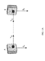
- FIG. 1A shows the simplest situation in which two nodes can see each other.
- two smart cameras equipped with accelerometers and/or compass sensors can see each other and can determine their relative position and orientation up to a scale from the available measurements. For example, using the location of each blinking light source and the observed size and shape of the observed camera B, the observing camera A can determine the distance V ab to the observed camera B. Similarly, smart camera B can determine the distance V ba to the observed smart camera A. In some embodiments, smart cameras A and B communicate wirelessly to reach a consensus on the distance between the cameras, such as an average of V ab and V ba . These measurements allow two smart cameras to determine their relative position and orientation up to a scale factor. In some embodiments, the distance can be predetermined using other methods, such as manual setting of a parameter or by IR range finding.
- the resulting model of orientation and location of nearby cameras can be used to create a 3D model of the location of smart cameras. Accordingly, a stereoscopic image can be extrapolated based on a derived fundamental matrix or epipolar geometry using techniques known to a person of ordinary skill in the art. Similarly, the techniques used for corresponding epipolar pixels of nearby cameras described in U.S. Pat. Nos. 7,421,113 and 7,522,765 can be used.
- the accelerometer measurements (such as the direction of gravity g a or g b , and/or solid-state compass measurements (such as the direction of magnetic north) provide another independent source of information, about the orientation of the cameras with respect to the vertical axis.
- the smart camera nodes can also be related by a sparse web of wireless communication links. These links also depend upon the layout of the sensors since signal strength falls of with increasing distance. Taken together, these visibility and communication links induce a natural notion of locality where each camera can discover, localize and communicate with other camera systems in its immediate vicinity. This localization capability provides a basis on which each camera can correlate its own image measurements with those obtained from other neighboring vantage points and, hence, localize targets moving through its area of regard.
- FIG. 1B illustrates an exemplary situation where a target moving through the scene is localized in space by combining bearing measurements obtained from a variety of vantage points.
- a sighting Each observation of a candidate target (i.e. something that could be a target in the image) in an image is referred to as a sighting.
- Sightings can also be referred to as a target sightings, as each sighting can be considered an as-yet-unverified observation of a target.
- Each sighting indicates the presence of a candidate target in the image plane.
- Each bearing measurement e.g.
- the vector from a camera to a sighting allows the camera to determine the range to the associated target by looking for confirming evidence from at least two other cameras.
- the bearing measurements obtained from two or more smart camera systems can be fused via triangulation to determine the position of the targets in three dimensions. When three or more smart camera systems are viewing the same area of space redundant measurements are available which can be used to help eliminate false tracks. Collaborative tracking can be done when the bearing measurements can be relayed to a central location for processing.
- smart cameras 12 , 14 , and 16 observe object 20 as it moves through the image planes of each camera. Smart cameras 12 , 14 , and 16 make a first sighting at position 22 , and a second sighting at position 24 .
- bearings measurements 32 can used to determine position 22 in a 3D coordinate system; at position 24 , bearings measurements 34 can used to determine position 24 in the 3D coordinate system.
- each, or at least one, camera localizes targets on its own by communicating with its neighbors. This is accomplished by having a node communicate its sightings to other nodes in its immediate neighborhood. Once this has been done, each camera independently considers every pair of sighting measurements that it learns about, for each of the resulting candidate points a camera looks for confirming sighting measurements in other views. The end result of this procedure is a set of candidate points in space which can be called targets.
- each camera In addition to the set of targets derived from the sighting measurements, each camera also maintains a set of active tracks corresponding to trajectories of targets over time.
- These track structures can be extrapolated and stored in an onboard memory associated with each smart camera.
- a subset of the tracks can be transmitted to a central device, wirelessly, for archiving and further analysis, such as correlation with image/object semantic information or other related trajectories.
- Each of these track structures can contain a number of fields which are described in Table I.
- each track is a state vector which encodes the position and velocity of the associated target along with the covariance matrices that are required to implement a Kalman filter tracker.
- Each track is tagged with a globally unique identifier which persists as the object moves through the entire scene.
- the track structure also contains timestamps indicating the first time that the tracked object was detected and the last time that the track was updated.
- each camera samples and stores state vector and covariance matrix periodically, creating a record of the time variance of the track of each object.
- the position and velocity vector is a two dimensional vector (x, y), while other embodiments may utilize a three dimensional vector (x, y, z).
- the velocity vector can be extracted from changes in the position vector.
- every smart camera participating can solve a data association problem, resolving the relationship between the current tracks and the current targets.
- the nodes on the left 40 depict the current tracks while the nodes on the 42 right depict the current targets.
- each participating smart camera node can associate the detected targets with the tracks that it currently maintains.
- the system finds the best matching target - if any. In some embodiments, the system then selects between multiple associations by favoring tracks with longer histories.
- heuristics can be used, such as a confidence match using dead reckoning from past trajectory information or by extrapolating an expected position based on an interpolation or extrapolation of past and/or future points associated with a track.
- the ultimate matches are indicated by solid lines while the dashed lines indicate possible matches that are rejected.
- This scheme causes the overall system to maintain the identities of the tracked objects as they move through the system. Detected targets that are not explained by any of the existing tracks can be used to create new tracks. When a smart camera creates such a track it concatenates its own unique smart camera identifier with a local counter value to form a globally unique identifier. This global identifier is then used in all subsequent communications and effectively travels with the object as it moves through the network.
- the cameras can determine the most probable target based on the Kalman filter estimate and covariance and link the nodes as shown. Note that at this stage there may be more than one track associated with each target. Each target can be assigned its best match among the list of possible tracks by considering the relative age of the tracks and choosing the oldest one. The measurements associated with this target are then used to update the Kalman filter associated with the winning track. Tracks that are not updated are propagated forward allowing for short periods of occlusion or tracker failure. Tracks that are starved of updates are eventually elided from the list. In this manner, short ephemeral tracks are removed from the system in favor of longer lasting records.
- a camera Once a camera has resolved the relationship between tracks and targets and updated the list of tracks, it can send its current list of active tracks to its neighbors receiving, in turn, a list of all the targets that they are tracking. In this manner, information about tracks and target identities is propagated through the network allowing for seamless handoff as targets move throughout an extended scene.
- ephemeral tracks may be introduced from time to time due to tracker failures or glitches but these can be corrected eventually since the system can be biased to prefer older labels for tracks wherever possible. This can cause occasional miss-associations in the triangulation phase. These cases typically produce outlier targets which do not win data association competitions and are thus starved for updates. Tracks which do not receive a sufficient number of updates per second can be eliminated and/or removed from memory. In some embodiment, a track must receive at least 2 updates per second.
- This protocol allows the network of distributed, loosely coupled smart camera systems to achieve consensus on target identities. By preserving target identifiers, the entire system is able to track targets over extended areas without requiring a central coordinating authority.
- track and/or target updates can be communicated wirelessly on an ad hoc basis to nearby cameras, such as those that appear in a smart camera's image plane. Because this embodiment of the protocol only requires communication among near neighbors it can be scaled to networks of arbitrary size.
- the local distribution of target and/or track information can include those smart cameras that can see the sending smart camera, as well as those that can be seen by the sending camera. That is, the distribution can include both those cameras that can be seen, as well as those that have sent updates to the camera current update.
- some or all updates can be sent to a central controller for archival or further analysis.
- Targets which are not matched with any existing tracks are used to form new tracks.
- each participating camera can send to its neighbors a list of its current bearing measurements (step iii of the algorithm). It also sends out a list of its current tracks (step viii). Neighbors can include those cameras that a camera can see, those that can see it, a predetermined group of nearby cameras, or any combination thereof.
- the tracking algorithm includes a main loop 100 , which is performed by a processor in each of the smart cameras as they work together to track an object.
- a camera processes an image frame and extracts sightings. This can be by any method described herein.
- image processing can include a preprocessing step, which can include filtering, such as smoothing, color extraction, enhancing sharpness, brightness, or contrast, compression, or the like.
- Image processing can include segmentation of the image to determine salient features in the image, any known manner, including that explain below.
- segmentation allows the camera to identify objects in an image.
- one noon image segmentation scheme applies temporal analysis to the image to identify objects in the image that moved relative to background.
- Another available segmentation scheme includes pattern recognition, such as facial recognition.
- Another segmentation scheme may include increasing the contrast of an image to reduce the available shades or colors in an image for helping select those portions that have the same shading or color.
- 3-D cameras are employed that can separate objects in the foreground from those in the background by observing the image depth.
- image depth analysis is provided by a single two-dimensional camera with an IR rangefinder.
- image segmentation is a hashing segmentation scheme, such as that disclosed in concurrently filed application, titled “Image Segmentation for Distributed Target Tracking and Scene Analysis,”.
- smart camera is able to identify portions of the image that are candidate objects for tracking (i.e. sightings). These sightings are then identified and temporarily stored, such as in array.
- sightings identified in step 102 are transmitted to neighboring cameras. Neighboring cameras also transmit sightings, so that each camera can receive an additional list of sightings by neighboring cameras.
- the locally identified sightings are compared to the sightings received from neighboring cameras. Because the epipolar geometry is known prior to object tracking, as explained above, the pixel coordinates of the sighting in to neighboring image claims can be used to triangulate a three-dimensional location of the sighting using the epipolar geometry of the two (or more) neighboring cameras. It should therefore be understood that prior to step 102 , the epipolar geometry of each pair of neighboring cameras is determined as explained herein. In some embodiments, this triangulation step is used to identify corresponding sightings in the two image planes. That is, only certain pairs of sightings between adjacent cameras could possibly be the same sighting.
- the features of the sighting are used to determine which pairs of sightings to correlate and triangulate. For example, sightings can be required to have similar color or shape. If multiple neighboring smart cameras share information about the same sighting, any additional sightings (e.g. beyond two) can be used to add precision to triangulated position of the sighting or to verify accuracy.
- the result is a correlated group of one or more sightings that are correlated between the set of sightings observed and those received from adjacent camera devices.
- each camera matches the current sightings and their triangulated positions to its local database of past tracks. This concept is shown in FIG. 3B .
- FIG. 3B shows an exemplary embodiment of step 110 .
- Step 110 is used to identify new tracks and identify those existing tracks from prior frames that correlate to at least a subset of the current sightings and update those tracks.
- the current tracks or updates to current tracks can be transmitted to neighboring cameras. Similarly, tracks or updates to tracks can be received from neighboring cameras.
- the local database of tracks is updated to reflect the changes to tracks determined at step 110 and the received tracks from step 122 .
- the database of tracks, or a subset of the database of tracks is transmitted beyond the nearest neighbors, such as to a central controller for archival, analysis, or display.
- step 126 the transmittal to a single central hub or transmitting a subset of tracks, or only occasionally transmitting tracks, step 126 can be designed to reduce burden on available wireless bandwidth.
- FIG. 3B shows an exemplary embodiment of step 110 .
- the list of available candidates sightings is observed to determine if there are remaining unmatched candidates. If there are available candidates, at step 108 the next candidate saving is selected for matching to tracks.
- the position of the candidates adding is compared to known tracks in the local database to determine if the location matches the known trajectory of a recent track.
- the best match of a track and sighting pair will be selected. In some embodiments, this is necessary, because multiple tracks may match threshold criteria for the same candidate saving.
- the heuristic for determining the best match can be the any method described herein.
- the best match is determined to be the track the earliest first sighting.
- the match is used to update the matched track. In some embodiments, updating of the match track may overwrite the trajectory of the track. In other embodiments, updating the track may append the new position velocity to the trajectory of the existing track. Then, the loop repeats at step 107 .
- a new track may be created. That track's features can be populated based on the current sighting, including its location and the current time of the sighting. Then, the loop repeats at step 107 .
- Step 107 repeats until no remaining candidates are found in the image.
- the camera can determine whether there are any tracks in its track database that have not matched to a current sighting. If there are any unmatched tracks, at step 116 , a counter may be updated, assisted with track to indicate how long the track is existed without matching. In some embodiments, this count is reset whenever the track is matched to a candidate saving. In some embodiments, each time a track is matched to a candidate sighting, a last matched timestamp is updated for that track. Then, rather than using account at 116 the current timestamp can be compared to the last matched timestamp. If the time since last match exceeds a threshold, the track can be deleted.
- step 117 the count or difference in timestamps associated with the track, which indicates how long a track has gone unmatched, is compared a threshold criteria. If it exceeds these criteria, at step 118 , the track can be deleted from the track database. Then, the loop returns to step 115 .
- the loop can simply return to step 115 , with the recent lack of match noted in the updated count (or noted by not updating a timestamp for the track).
- step 115 method 110 exits and return step 122 .
- Each track structure contains the fields described earlier. Since these messages contain relatively little information and each camera only communicates with its near neighbors, the method makes efficient use of the available communication bandwidth which is often quite limited. This interval can be a separate interval from the frame rate.
- Information about the targets in the scene is generally distributed among the smart cameras in the network.
- information about the trajectory of a particular target is distributed among the smart camera nodes that viewed the target at various portions of its trajectory. These trajectory can linked by a common target id which can be used to correlate the information across the network.
- some embodiments employ a subscription model where a user can inject a request into the network indicating her interest in particular kinds of tracking events. This request can be broadcast periodically through the prevailing communication network to the individual camera nodes which would respond by sending back events that matched the criterion of the query.
- a user may indicate that she is interested in all tracks passing through a particular region in the scene or all tracks that persist for more than a certain amount of time.
- she may indicate interest in a particular set of target ids which could then be tracked over time with the information relayed back to the subscriber.
- This scheme can decouple the service providers, the individual smart camera nodes, from the service subscribers.
- the subscribers need not request information from particular nodes which could fail or be removed at any time but would rather phrase their request in terms of queries which would be broadcast to all of the nodes that may be able to provide them with the desired information.
- the network could service multiple applications for multiple subscribers concurrently.
- Target detection can entail any form of detection available in the art. This can include sophisticated target detection schemes such as face detection or pedestrian recognition which could cut down on false sightings. Additionally or alternatively, the detection scheme can be a hashing segmentation scheme, such as that disclosed in concurrently filed application, titled “Image Segmentation for Distributed Target Tracking and Scene Analysis,” which has common inventorship and is incorporated herein by reference. Furthermore, the target detection scheme could make use of a ranging device in conjunction with image processing, such as is illustrated in the methods and systems disclosed in concurrently filed application, titled “Scene Analysis Using Image and Range Data,” which has common inventorship and is incorporated herein by reference.
- each smart camera device 210 includes a processor 222 , which can include a dual core 600 MHz Blackfin processor from Analog Devices and suitable supporting hardware.
- An exemplary processor 222 includes a Digital Signal Processor designed to support high performance image processing operations in low power devices, such as cameras and cell phones.
- Each smart camera device 210 includes an imaging device 224 coupled to the other components, including processor 222 via one or more internal busses. This imaging device can include a digital camera sensor, optics, image processing or filtering hardware, and the like.
- An exemplary imaging device 224 is suitable for observing an image field and capturing an image for us by the system and methods for tracking described herein.
- imanging device 224 includes an Aptina CMOS imager, such as an XVGA resolution imager (720 ⁇ 480) and a fisheye lens which affords a field of view of approximately 180 degrees.
- Each imaging device also includes a transceiver 225 for communicating with other camera devices 210 and/or a central controller 250 .
- Transceiver 225 can include a wireless transceiver and antenna, such as a Zigbee wireless communication module, an Ethernet controller.
- the smart camera device 210 can also include sensors 228 , such as a three axis accelerometer, as well as an 850 nm high intensity infrared signaling light or other positioning beacon 232 .
- Image and track data can be captured and stored in memory 230 , which can include program and data memory.
- Memory 230 can store a database of tracks, which may include archival of recent tracks, and may further include memory configured to store data about current sightings, including a cache of current candidate targets observed and received from other smart camera devices.
- each smart camera device 210 is a low power device, which may be powered by a battery.
- a smart camera device can consume less than 3 watts of power in operation and can be powered for 6 hours or more with a 6 ounce Lithium Ion battery pack. Alternatively, lower power can be used to extend battery life and/or an external power source can be provided.
- a plurality of smart camera devices 210 can be placed about an environment for observation, such that at least a subset of cameras is arranged such that its image plane intersects with the image plane of a subset of nearby cameras.
- the set of cameras can also include some smart camera devices that do not have an intersecting image plane, such as a camera whose beacon 232 is observable by another camera, but whose image plane does not include any other beacons. These may be used to supplement the systems described herein to allow for a larger observable area.
- Each smart camera device communicates with neighboring camera devices via tranciever 226 .
- This can include communication via peer-to-peer communication or network 240 , which can include a wi-fi network including one or more hubs or routers, or an ad hoc or mesh network for more flexible communication.
- Network 240 need not have separate components, and may not necessarily allow all camera devices (which can be considered nodes in the overall camera network) to communication. It will be understood that a system using peer-to-peer communication can be described as having a network 240 .
- smart camera nodes to 10 can communicate if a central controller 250 .
- Central controller 250 can include a server, computer, mobile device, PC, Mac, or higher powered computing device relative to smart camera devices 210 .
- Central control 250 can receive periodic updates on important tracks, which may include all tracks, or a subset of tracks observed by smart camera devices 210 .
- Controller 250 can then store these tracks in memory 252 .
- Memory 252 can include instruction and data memory for operating controller 250 .
- Memory 252 can include a database of archived tracks, as well as image data (which may be received periodically from camera devices 210 or environment model for the environment in which the plurality of smart camera devices are deployed.
- Tracks stored in memory 252 can be displayed to the user via user interface 254 .
- User-interface 254 can include a GUI, a readable file, such as an XML file, and may include sending visual or data information to a user via a network.
- tracks stored in memory 252 can be sent to a user's mobile device via a network.
- Information sent to a user can include filterable information selected from a database in memory 252 .
- central controller 250 maintains a list of alert criteria for comparing to tracks received from camera devices and/or stored in memory 252 .
- processor 250 can cause alerts to be sent to user via interface 254 . These alerts may include information about the track or tracks that triggered the alert. Alerts can be used in a surveillance environment to identify instances where a security zone has been breached.
- memory 252 includes instructions to allow central controller 250 to send up dates or configuration information to nodes in the camera network. This allows some degree of central control for rolling out updates to a system, while allowing much of the routine tracking steps to be performed independently by camera nodes to 10 on an ad hoc basis. This can reduce overall system bandwidth requirements, and can allow low powered processing of image data at each node, rather than central processing of all image data.
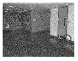
- FIG. 5 shows a photo of a room where to cameras, legal one and three, have been placed on the walls in inconspicuous locations that are visible to one another. These locations can be chosen such that a person being tracked is not easily where of the location of the cameras.
- the cameras were automatically localized as described in U.S. Pat. Nos. 7,421,113 and 7,522,765 and then used to track targets moving through the area of regard in real time.
- the first stage in the target tracking procedure can include an adaptive background subtraction phase which determines which aspects of the image have changed significantly over time.
- a connected component phase can be applied to the resulting binary image to find the most significant moving targets in the scene.
- the result of this analysis is a set of bearing vectors emanating from each of the cameras into the scene. All of the real-time image processing can occur on the smart camera nodes themselves. Only the final sighting vectors associated with the targets are relayed over the Zigbee wireless network for further processing. This approach can allow one to distribute the most computationally intensive aspects of the tracking procedure onto the smart camera nodes and avoid having to relay video imagery over the limited wireless bandwidth.
- each smart camera system extracts sighting measurements from the images at a rate of 15 frames per second.
- FIG. 6 illustrates that smart cameras can automatically determine their positions and orientations with respect to each other in 3D in a matter of seconds.
- FIG. 6 shows exemplary three-dimensional environment with environmental features removed. A plurality of cameras in the 3D environment observe each other and readily determine their relative position within the environment.
- FIGS. 7 and 8 shows the results of two tracking experiments.
- the camera network was used to track a single person who walked into and around the first floor area and eventually exited through the same point he entered.
- the second experiment shows the system tracking two people who start off walking together and then split off onto two separate trajectories.
- the targets were correctly tracked and associated throughout the sequence in real time through multiple camera handoffs since the structure of the scene ensured that no one smart camera had the targets in view throughout.
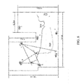
- FIG. 7 shows a snapshot of a real time tracking experiment showing the current position and past trajectory of a target moving through the scene.
- the lines emanating from the cameras 1 , 2 , and 3 represent sighting measurements which are triangulated to determine target location.
- the camera network includes cameras 1 - 8 .
- cameras 1 , 2 , and 3 have a line of sight to a first point where an target originates.
- the curve illustrates that objects observed track through the camera network.
- FIG. 8 shows a snapshot of a real time tracking experiment showing the current position and past trajectory 302 and 304 of two targets moving through the scene. Spurious sighting measurements, caused by a reflection in the window, will not be confirmed other cameras and, hence, discarded.
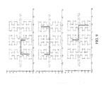
- FIG. 9 shows an example of an indoor environment reminiscent of an airport. This particular scene is monitored by a collection of 168 cameras mounted along the walls. The cameras could only see targets within a fixed distance of their positions.
- the system was able to concurrently track a collection of 100 simulated targets over 100 timesteps.
- the average number of messages received by each node was recorded on every timestep and the results are plotted on the graph in FIG. 10 , which indicates the average number of messages received by each of the nodes over the course of the simulation.
- This plot includes both types of messages exchanged over the network, sighting measurements and track information.
- FIG. 9 shows the trajectories recovered for a few of the tracked targets. Note that the targets move throughout the environment between many cameras but the tracking system correctly maintains their identities.
- This simulation experiment modeled the layout of an airport. The system successfully tracked 100 targets using 168 smart camera nodes. The figure shows trajectories of individual targets successfully tracked throughout the environment. The small circles denote camera positions, the light lines indicate walls.
- FIG. 2 shows method 300 for segmenting an image.
- a feature space is divided into and a predetermined number, n, of splitting planes.
- This step can include randomly assigning and feature planes and using a calibration image or a first image to the splitting plane for a given orientation. For example, the position of each plane can be chosen such that feature vectors (e.g. those feature vectors associated with each pixel in a test image) within the feature space are evenly divided on either side of the splitting plane.
- each splitting plane can be created by choosing a random normal vector and assigning a decision point along that vector such that the decision point is at the mean or median of the distribution of feature vectors (e.g. pixels projected on that normal vector).
- step 302 takes into account predetermined splitting planes that have been created via prior training or have been manually assigned.
- the splitting planes can include a combination of random splitting planes and preassigned splitting planes.
- each feature vector image (or a subset of the feature vectors in image) is hashed using the splitting planes.
- This process can be computationally simple as each bit in the hash simply determines which side of the splitting plane the feature vector resides. Because only a bit is used for this hash, additional computational overhead needed for deriving the Euclidean distance from the splitting claim is not necessary.
- Step 304 can be an iterative loop whereby each feature vector is taken and compared in succession to each of the n splitting planes. It will be appreciated that massive parallelism and may be possible using the right processor, such as a DSP or graphics processor, to perform this step.
- the algorithm proceeds to step 306 .
- the number of feature vectors resident in each cell in the feature space is counted.
- the residency counts for each cell in the feature space are compared to choose a number of local maxima.
- the number of local maxima, M is predetermined prior to image processing.
- the number of local maxima, M is derived dynamically from the image based on the results of the residency counts of each cell in the feature space.
- the maximum number of local maxima, M can be determined based on the number of splitting planes used and the Hamming distance requirements for clusters used to image segmentation. Once the local maxima are identified, these can be used as the center of each cluster used for image segmentation.
- each feature vector under test can be assigned to each of the cluster centers determined in step 308 .
- this assignment has low computational is and where.
- In overhead because the hash of each feature vector is compared to each of the cluster centers and the cluster having the nearest Hamming distance to the hash of the vector is selected as the cluster to which the feature vector will be assigned.
- ties between competing clusters i.e. clusters that are the same Hamming distance away from the hashed feature vector
- image segments can be identified within the image. For example, adjacent pixels in the image plane that have had their feature vectors assigned to the same cluster can be considered part of the same image segment. Any known technique can be used, such as minimum threshold sizes for segments of adjacent pixels. In this way, image segments can be rapidly deduced from the image by scanning pixels in the image plane and determining whether they share the same cluster in the feature space.
- step 314 may optionally adjust the splitting planes based on the results in step 312 .
- the results of step 312 can be compared via a consistency score with a desired segmentation result. Based on this result, the splitting planes can be adjusted to improve this consistency score.
- incremental improvement of splitting planes is done in real time based on other criteria, such as reducing the number of identified segments in step 312 or increasing the number of identified segments in step 312 to reach a desired range of segments.
- Suitable processing environments can include Intel, PowerPC, ARM, or other CPU-based systems having memory and a processor, but can also include any suitable embedded systems, DSP, GPU, APU, or other multi-core processing environment including related hardware and memory.
- the algorithms taught herein can be implemented by dedicated logic.
- execution of these algorithm and techniques is not limited to a single processor environment, and can, in some contemplated embodiments, be performed in a client server environment, a cloud computing environment, multicore environment, multithreaded environment, mobile device or devices, etc.
Landscapes
- Engineering & Computer Science (AREA)
- Physics & Mathematics (AREA)
- General Physics & Mathematics (AREA)
- Theoretical Computer Science (AREA)
- Computer Vision & Pattern Recognition (AREA)
- Multimedia (AREA)
- Image Analysis (AREA)
- Studio Devices (AREA)
Abstract
Description
- The present application claims priority to provisional patent applications 61/418,789, 61/418,805, and 61/418,799 which are incorporated by reference in their entirety.
- The present application relates to concurrently filed patent applications entitled “Scene Analysis Using Image and Range Data” and “Image Segmentation for Distributed Target Tracking and Scene Analysis” both of which are incorporated by reference in their entirety and filed on the same day as the present application entitled “Distributed Target Tracking Using Self Localizing Smart Camera.”
- The present invention relates generally to machine vision systems and methods and specifically to object tracking and scene analysis for distributed or mobile applications.
- The decreasing cost and increasing performance of embedded smart camera systems makes it attractive to consider applying them to a variety of surveillance and tracking applications. In the near future it may be possible to deploy small, unobtrusive smart cameras in the same way that one deploys light bulbs, providing ubiquitous coverage of extended areas. It would be therefore desirable to have a system and method for using such a system to track passengers at an airport from the time that they arrive at curbside check in to the time that they board their flight. Similarly, it would be desirable to have a system and method to monitor the movements elderly or infirm individuals in their homes in order to improve their quality of care.
- There is a need to reliably detect, localize and track targets as they move over an extended area of regard covered by multiple distributed smart cameras. However, there is presently a lack of systems and method that allow detection and tracking which can be distributed over multiple sensors without requiring excessive amounts of communication. These systems would ideally be scalable to allow for deployments that may involve thousands of cameras distributed over extended regions and be robust to failure so that the overall system responds gracefully when individual sensors are added or removed asynchronously.
- Most detection and tracking systems that have been developed or proposed fuse information from multiple sensors at a central point in the network which is responsible for establishing tracks and associating measurements from different views. As the number of sensors grows, increasing demands are placed on the communication system which must route information to these processing centers. Moreover, failures in these processing centers can often render the entire network useless.
- There have been some approaches to tracking using camera networks. For example Kayumbi, Anjum and Cavallaro describe a scheme for localizing soccer players with a network of distributed cameras. (G. Kayumbi, N. Anjum, and A. Cavallaro, “Global trajectory reconstruction from distributed visual sensors,” in International Conference on Distributed Smart Cameras 08, 2008, pp. 1-8.)
- Quinn et. al. propose a scheme for calibrating a set of cameras in a room and using them to track targets. (M. Quinn, R. Mudumbai, T. Kuo, Z. Ni, C. De Leo, and B. S. Manjunath, “Visnet: A distributed vision testbed,” in ACM/IEEE International Conference on Distributed Smart Cameras, 2008, September 2008, pp. 364-371.) Their approach splits the tracking task between a collection of smart camera nodes and a higher level process which fuses the sightings from these cameras. However, there is still a need to develop protocols that can be employed on large networks covering extended areas.
- Medeiros, Park and Kak [9] describes a distributed approach to triangulating targets and distributing the tracking task over multiple nodes. (H. Medeiros, J. Park, and A. C. Kak, “Distributed object tracking using a cluster-based kalman filter in wireless camera networks,” IEEE Journal of Selected Topics in Signal Processing, vol. 2, no. 4, pp. 448̂63, August 2008.) This protocol involves electing a leader associated with every tracked object which is responsible for maintaining that track. Klausnet Tengg and Rinner describe a distributed multilevel approach to fusing the measurements gleaned from a network of smart cameras. (Klausner A. Tengg A. Rinner B., “Distributed multilevel data fusion for networked embedded systems,” in Selected Topics in Signal Processing, IEEE Journal of Publication Date: August 2008, August 2008.) There remains a need, as networks grow to allow the protocol to be scalable, such as allowing the cameras to be viewed as peers.
- Embodiments of the present invention address and overcome one or more of the above shortcomings and drawbacks, by providing devices, systems, and methods for tracking objects moving in an multi-camera environment. This technology is particularly well-suited for, but by no means limited to, a surveillance system utilizing multiple cameras with intersecting fields of view.
- Embodiments of the present invention are directed to a method for tracking one or more targets including determining, by a first camera device, the location of a second camera device further determining by a first camera device, the location of a second camera device. The method captures a first image by the first camera device and a second image by the second camera device. The method extracts a first set of one or more target sightings in the first image and a second set of one or more target sightings in the second image using an image segmentation technique. The method further exchanges information about the first and second sets of one or more target sightings. The method triangulates target sightings from the first and second set of one or more target sightings to create a third set of target sightings. The method further matches at least a subset of the third set of target sightings to known tracks maintained by the first camera.
- According to one embodiment of the invention, the step of exchanging information occurs over a peer-to-peer wireless network. According to one aspect of the invention, the step of determining the location of a second camera is performed by observing the location of a blinking light associated with the second camera in an image plane of the first camera.
- According to another aspect of the invention, the method further stores at least one updated track in a database of the first imaging device based on the matching step. According to yet another aspect of the invention, the method further communicates, by the first camera, at least on updated track that was matched by the matching step. According to yet another aspect of the invention, the method includes receiving, by a central controller, track information relating to at least a subset of the first and second first and second set of one or more target sightings to create a third set of target sightings; and storing, by the central controller, the track information.
- According to yet another aspect of the invention, track information is displayed to a user. According to yet another aspect of the invention, the method deletes a first subset of one or more known tracks maintained by the first camera if the first subset of known tracks fails to match any of third set of target sightings after a predetermined amount of time. According to yet another aspect of the invention, the step of matching includes choosing the oldest known track when more than one known track matches at least one target sighting. According to yet another aspect of the invention, the method transmits information about known tracks, by the first camera devices, to at least a subset of neighboring camera devices.
- In another embodiment of the invention, the present invention is directed to a camera device for tracking objects comprising an imaging device capable of capturing a first image. A processor is configured to determine, the location of a second camera device further determining by a first camera device, the location of a second camera device. The processor is configured to extract a first set of one or more target sightings in the first image using an image segmentation technique. The processor is capable of transmitting to a second camera device at least a port of the first set of one or more target sightings. The processor is configured to receive from the second camera device a second set of one or more target sightings in a second image captured by the second camera device. The processor is configured to triangulate target sightings from the first and second set of one or more target sightings to create a third set of target sightings. The processor is configured to match at least a subset of the third set of target sightings to known tracks maintained by the first camera.
- According to one aspect of the invention, a transceiver is configured to exchange information with the second camera over a peer-to-peer wireless network. According to another aspect of the invention, a light source is configured to communicate an identity of the camera device to the second camera device. According to yet another aspect of the invention, memory is configured to store at least one updated track in a database of the first imaging device based on the matching step.
- According to another aspect of the invention, the processor is further configured to communicate at least on updated track that was matched by the matching step to the second camera device. According to yet another aspect of the invention, the processor is further configured to send information relating to at least a subset of the first and second first and second set of one or more target sightings to create a third set of target sightings to a central controller. According to still another aspect of the invention, the processor is further configured to delete a first subset of one or more known tracks maintained by the first camera if the first subset of known tracks fails to match any of third set of target sightings after a predetermined amount of time. According to yet another aspect of the invention, the processor is further configured to choose the oldest known track when more than one known track matches at least one target sighting. According to yet another aspect of the invention, the processor is further configured to transmit information about known tracks to at least a subset of neighboring camera devices.
- Additional features and advantages of the invention will be made apparent from the following detailed description of illustrative embodiments that proceeds with reference to the accompanying drawings..
- The patent or application file contains at least one drawing executed in color. Copies of this patent or patent application publication with color drawing(s) will be provided by the Office upon request and payment of the necessary fee.
- The foregoing and other aspects of the present invention are best understood from the following detailed description when read in connection with the accompanying drawings. For the purpose of illustrating the invention, there is shown in the drawings embodiments that are presently preferred, it being understood, however, that the invention is not limited to the specific instrumentalities disclosed. Included in the drawings are the following Figures:
-
FIG. 1A is a simplified diagram of an exemplary camera network for use with the present application. -
FIG. 1B is a top view an exemplary camera network for use with the present application detecting targets; -
FIG. 2 is a tree diagram showing an exemplary association between tracks and targets; -
FIG. 3A is a flow chart showing operation of an exemplary algorithm for use with tracking targets in the camera network; -
FIG. 3B is a flow chart showing operation of an exemplary algorithm for use with tracking targets in the camera network; -
FIG. 4A is a photographic view showing the outside and inside of exemplary cameras for use with embodiments of the present application; -
FIG. 4A is a block diagram of an exemplary camera and network for use with embodiments of the present application; -
FIG. 5 is a photographic view of exemplary cameras for use with embodiments of the present application placed in a tracking environment; -
FIG. 6 is a 3-D view of exemplary cameras for use with embodiments of the present application placed in a tracking environment; -
FIG. 7 is a plot of a tracked object path in relation to the cameras tracking the target; -
FIG. 8 is a plot of two tracked object path in relation to the cameras tracking the target; -
FIG. 9 is a plot of a tracked object path in relation to the cameras tracking the target in a simulation; -
FIG. 10 is a plot of network bandwidth utilization when testing an embodiment of the present application; and -
FIG. 11 is a flow chart showing operation of an exemplary algorithm segmenting images to identify tracking targets in some embodiments of the tracking camera network. - The present application describes an approach to detection and tracking for smart camera networks which is generally decentralized. This allows the smart cameras to automatically detect and localize other camera nodes with overlapping fields of regard and to establish communication graphs which reflect how the nodes will interact to fuse measurements in the network. Embodiments can utilize network protocols with limited communication requirements, which allow the system to distribute detection and tracking problems evenly through the network accounting for sensor handoffs in a seamless manner.
- In this approach each of the cameras, or a subset of the cameras, independently analyzes its video imagery to find moving targets in its field of view the results of this analysis are fused in the network to triangulate the location of the objects of interest in space. This approach devolves the low level image processing to the smart cameras and allows the nodes to use the limited wireless bandwidth more efficiently since they need only share sighting measurements and track data with their near neighbors. Using this approach we have been able to demonstrate real time tracking of targets over an extended area using a collection of embedded smart cameras, deployed in an ad-hoc manner and connected by a wireless communication network.
- The approach can also distribute knowledge about the state of tracked objects throughout the network. This information can then be harvested through distributed queries which allow network participants to subscribe to different kinds of events that they may be interested in. For example, a process operating on a processor associated with a camera or a network of cameras could request to be updated on all movements of a particular target. Similarly, a process may want to be told about all targets that pass through a particular area of interest. These approaches can be used to develop simple but robust tracking systems that respect the constraints of a distributed deployment context.
- The approach leverages the fact that the nodes can recover the relative position and orientation of their neighbors automatically. This makes it feasible to consider deploying large collections of smart camera nodes in an ad-hoc manner since one need not manually survey their relative locations. Furthermore, it allows the smart cameras to rapidly and reliably determine the nodes with which it must collaborate in the tracking application. This can reduce the cost and complexity of fielding multi camera surveillance systems and allows them to be applied to a wider range of applications
- A suitable camera network for use with these methods and systems include a self-localizing camera network, such as that described in commonly assigned U.S. Pat. Nos. 7,421,113 and 7,522,765 titled “A SYSTEM AND METHOD FOR LOCALIZING IMAGING DEVICES,” which are incorporated herein by reference.
- In this localization scheme each of the embedded camera systems can be equipped with a controllable light source, typically an IR or visible LED, and a wireless communication system. Each smart camera uses its light source as a blinker to transmit a temporally coded binary sequence which serves as a unique identifier. The cameras detect other nodes in their field of view by analyzing image sequences to detect blinking pixels and, hence, are able to determine the relative bearing to other visible nodes. By knowing the location of the light source of other visible cameras, each viewing camera can determine the location of other cameras in the image plane. In some embodiments, the viewing camera can take into account the geometry and orientation of camera being observed (which may be obtained by peer-to-peer wireless communication between cameras) and determine an offset in the image plane to determine the location of the lens or optical sensor of the observed camera. This can increase accuracy, in some embodiments. In other embodiments, the location of the light source is a sufficient approximation of the location of the observed camera. In some embodiments the location of the blinking LED or the extrapolated location of the lens of the observed is used to determine an epipolar pixel associated with the observed camera's location.
- This determination can be made by a CPU associated with the camera, which may include an embedded processor, mobile device, cloud computing environment, client-server environment, DSP, or dedicated hardware circuit capable of performing the methods disclosed herein.
-
FIG. 1A shows the simplest situation in which two nodes can see each other. In this embodiment, two smart cameras equipped with accelerometers and/or compass sensors can see each other and can determine their relative position and orientation up to a scale from the available measurements. For example, using the location of each blinking light source and the observed size and shape of the observed camera B, the observing camera A can determine the distance Vab to the observed camera B. Similarly, smart camera B can determine the distance Vba to the observed smart camera A. In some embodiments, smart cameras A and B communicate wirelessly to reach a consensus on the distance between the cameras, such as an average of Vab and Vba. These measurements allow two smart cameras to determine their relative position and orientation up to a scale factor. In some embodiments, the distance can be predetermined using other methods, such as manual setting of a parameter or by IR range finding. - The resulting model of orientation and location of nearby cameras can be used to create a 3D model of the location of smart cameras. Accordingly, a stereoscopic image can be extrapolated based on a derived fundamental matrix or epipolar geometry using techniques known to a person of ordinary skill in the art. Similarly, the techniques used for corresponding epipolar pixels of nearby cameras described in U.S. Pat. Nos. 7,421,113 and 7,522,765 can be used.
- In some embodiments the accelerometer measurements (such as the direction of gravity ga or gb, and/or solid-state compass measurements (such as the direction of magnetic north) provide another independent source of information, about the orientation of the cameras with respect to the vertical axis.
- Larger networks can be localized by leveraging this relative localization capability. When a collection of smart cameras is deployed in an environment, these visibility relationships induce a sparse graph among the cameras. These measurements can be used to localize the entire network up to scale. The scheme provides a fast, reliable method for automatically localizing large ensembles of smart camera systems that are deployed in an ad-hoc manner.
- In addition to these visibility relationships, the smart camera nodes can also be related by a sparse web of wireless communication links. These links also depend upon the layout of the sensors since signal strength falls of with increasing distance. Taken together, these visibility and communication links induce a natural notion of locality where each camera can discover, localize and communicate with other camera systems in its immediate vicinity. This localization capability provides a basis on which each camera can correlate its own image measurements with those obtained from other neighboring vantage points and, hence, localize targets moving through its area of regard.
- The measurements obtained from camera systems can be useful when they are combined together as depicted in
FIG. 1B .FIG. 1B illustrates an exemplary situation where a target moving through the scene is localized in space by combining bearing measurements obtained from a variety of vantage points. Each observation of a candidate target (i.e. something that could be a target in the image) in an image is referred to as a sighting. Sightings can also be referred to as a target sightings, as each sighting can be considered an as-yet-unverified observation of a target. Each sighting indicates the presence of a candidate target in the image plane. Each bearing measurement (e.g. the vector from a camera to a sighting) allows the camera to determine the range to the associated target by looking for confirming evidence from at least two other cameras. The bearing measurements obtained from two or more smart camera systems can be fused via triangulation to determine the position of the targets in three dimensions. When three or more smart camera systems are viewing the same area of space redundant measurements are available which can be used to help eliminate false tracks. Collaborative tracking can be done when the bearing measurements can be relayed to a central location for processing. - In
FIG. 1B ,smart cameras object 20 as it moves through the image planes of each camera.Smart cameras position 22, and a second sighting atposition 24. Atposition 22,bearings measurements 32 can used to determineposition 22 in a 3D coordinate system; atposition 24,bearings measurements 34 can used to determineposition 24 in the 3D coordinate system. - Using a distributed approach each, or at least one, camera localizes targets on its own by communicating with its neighbors. This is accomplished by having a node communicate its sightings to other nodes in its immediate neighborhood. Once this has been done, each camera independently considers every pair of sighting measurements that it learns about, for each of the resulting candidate points a camera looks for confirming sighting measurements in other views. The end result of this procedure is a set of candidate points in space which can be called targets.
- In addition to the set of targets derived from the sighting measurements, each camera also maintains a set of active tracks corresponding to trajectories of targets over time. These track structures can be extrapolated and stored in an onboard memory associated with each smart camera. In some embodiments, a subset of the tracks can be transmitted to a central device, wirelessly, for archiving and further analysis, such as correlation with image/object semantic information or other related trajectories. Each of these track structures can contain a number of fields which are described in Table I.
-
TABLE I Fields associated with each track data structure (x, y, vx, vy) State vector encoding the position and velocity of C Covariance matrix associated with the state estimate track id Globally unique identifier associated with the track. The smart camera that creates this track forms this number by concatenating its own unique first Time when the track was first timestamp created last Time when the track was timestamp last updated with a sighting - Associated with each track is a state vector which encodes the position and velocity of the associated target along with the covariance matrices that are required to implement a Kalman filter tracker. Each track is tagged with a globally unique identifier which persists as the object moves through the entire scene. The track structure also contains timestamps indicating the first time that the tracked object was detected and the last time that the track was updated. In some embodiments, each camera samples and stores state vector and covariance matrix periodically, creating a record of the time variance of the track of each object. In some embodiments, the position and velocity vector is a two dimensional vector (x, y), while other embodiments may utilize a three dimensional vector (x, y, z). The velocity vector can be extracted from changes in the position vector.
- On each cycle every smart camera participating can solve a data association problem, resolving the relationship between the current tracks and the current targets. One can model the situation in terms of a bipartite graph as shown in
FIG. 3 . Here the nodes on the left 40 depict the current tracks while the nodes on the 42 right depict the current targets. For a new image, each participating smart camera node can associate the detected targets with the tracks that it currently maintains. For each of the current tracks the system finds the best matching target - if any. In some embodiments, the system then selects between multiple associations by favoring tracks with longer histories. However, in some embodiments, other heuristics can be used, such as a confidence match using dead reckoning from past trajectory information or by extrapolating an expected position based on an interpolation or extrapolation of past and/or future points associated with a track. InFIG. 2A , the ultimate matches are indicated by solid lines while the dashed lines indicate possible matches that are rejected. This scheme causes the overall system to maintain the identities of the tracked objects as they move through the system. Detected targets that are not explained by any of the existing tracks can be used to create new tracks. When a smart camera creates such a track it concatenates its own unique smart camera identifier with a local counter value to form a globally unique identifier. This global identifier is then used in all subsequent communications and effectively travels with the object as it moves through the network. - For each track the cameras can determine the most probable target based on the Kalman filter estimate and covariance and link the nodes as shown. Note that at this stage there may be more than one track associated with each target. Each target can be assigned its best match among the list of possible tracks by considering the relative age of the tracks and choosing the oldest one. The measurements associated with this target are then used to update the Kalman filter associated with the winning track. Tracks that are not updated are propagated forward allowing for short periods of occlusion or tracker failure. Tracks that are starved of updates are eventually elided from the list. In this manner, short ephemeral tracks are removed from the system in favor of longer lasting records. In this scheme we assume that the clocks on the smart camera nodes are roughly synchronized so that timestamps can be compared without issue. This scheme can be similar to the best-hypothesis tracking scheme described in Dirk Focken and R. Stiefelhagen, “Towards vision-based 3-d people tracking in a smart room,” in Proceedings of the Fourth IEEE International Conference on Multimodal Interfaces (ICMI 02), 2002.
- Once a camera has resolved the relationship between tracks and targets and updated the list of tracks, it can send its current list of active tracks to its neighbors receiving, in turn, a list of all the targets that they are tracking. In this manner, information about tracks and target identities is propagated through the network allowing for seamless handoff as targets move throughout an extended scene. Note that ephemeral tracks may be introduced from time to time due to tracker failures or glitches but these can be corrected eventually since the system can be biased to prefer older labels for tracks wherever possible. This can cause occasional miss-associations in the triangulation phase. These cases typically produce outlier targets which do not win data association competitions and are thus starved for updates. Tracks which do not receive a sufficient number of updates per second can be eliminated and/or removed from memory. In some embodiment, a track must receive at least 2 updates per second.
- This protocol allows the network of distributed, loosely coupled smart camera systems to achieve consensus on target identities. By preserving target identifiers, the entire system is able to track targets over extended areas without requiring a central coordinating authority.
- In some embodiments, track and/or target updates can be communicated wirelessly on an ad hoc basis to nearby cameras, such as those that appear in a smart camera's image plane. Because this embodiment of the protocol only requires communication among near neighbors it can be scaled to networks of arbitrary size. In some embodiments, the local distribution of target and/or track information can include those smart cameras that can see the sending smart camera, as well as those that can be seen by the sending camera. That is, the distribution can include both those cameras that can be seen, as well as those that have sent updates to the camera current update. Furthermore, in some embodiments, some or all updates can be sent to a central controller for archival or further analysis.
- The entire procedure carried out by the smart camera is outlined in
Algorithm 1 in pseudo-code. This algorithm is further elaborated inFIGS. 3A and 3B . -
Algorithm 1 Distributed Tracking Protocol - 1: loop
- 2: Process current image and extract sightings
- 3: Gather sighting measurements from neighboring cameras
- 4: Triangulate sightings to obtain positions of current targets
- 5: Match current targets against the list of current tracks and update the tracks that are matched.
- 6: Targets which are not matched with any existing tracks are used to form new tracks.
- 7: Prune tracks that have not been updated recently.
- 8: Gather current tracks from neighboring cameras removing duplicates as needed
- 9: end loop
- For each iteration of this illustrative tracking algorithm, each participating camera can send to its neighbors a list of its current bearing measurements (step iii of the algorithm). It also sends out a list of its current tracks (step viii). Neighbors can include those cameras that a camera can see, those that can see it, a predetermined group of nearby cameras, or any combination thereof.
- As shown in
FIG. 3A , the tracking algorithm includes amain loop 100, which is performed by a processor in each of the smart cameras as they work together to track an object. By each performingalgorithm 100 after cameras have localized neighboring cameras, neighboring cameras can operate on a peer-to-peer basis to track objects efficiently and accurately without necessarily having large processing capabilities.Loop 100 is performed after cameras are localized. Atstep 102, a camera processes an image frame and extracts sightings. This can be by any method described herein. In some embodiments, image processing can include a preprocessing step, which can include filtering, such as smoothing, color extraction, enhancing sharpness, brightness, or contrast, compression, or the like. Image processing can include segmentation of the image to determine salient features in the image, any known manner, including that explain below. In segmentation allows the camera to identify objects in an image. For example, one noon image segmentation scheme applies temporal analysis to the image to identify objects in the image that moved relative to background. Another available segmentation scheme includes pattern recognition, such as facial recognition. Another segmentation scheme may include increasing the contrast of an image to reduce the available shades or colors in an image for helping select those portions that have the same shading or color. In some embodiments, 3-D cameras are employed that can separate objects in the foreground from those in the background by observing the image depth. In some embodiments, image depth analysis is provided by a single two-dimensional camera with an IR rangefinder. In some embodiments, image segmentation is a hashing segmentation scheme, such as that disclosed in concurrently filed application, titled “Image Segmentation for Distributed Target Tracking and Scene Analysis,”. - By utilizing image segmentation or other image analysis, smart camera is able to identify portions of the image that are candidate objects for tracking (i.e. sightings). These sightings are then identified and temporarily stored, such as in array.
- At
step 104 sightings identified instep 102, sightings are transmitted to neighboring cameras. Neighboring cameras also transmit sightings, so that each camera can receive an additional list of sightings by neighboring cameras. - At
step 106, the locally identified sightings are compared to the sightings received from neighboring cameras. Because the epipolar geometry is known prior to object tracking, as explained above, the pixel coordinates of the sighting in to neighboring image claims can be used to triangulate a three-dimensional location of the sighting using the epipolar geometry of the two (or more) neighboring cameras. It should therefore be understood that prior to step 102, the epipolar geometry of each pair of neighboring cameras is determined as explained herein. In some embodiments, this triangulation step is used to identify corresponding sightings in the two image planes. That is, only certain pairs of sightings between adjacent cameras could possibly be the same sighting. In some embodiments, the features of the sighting are used to determine which pairs of sightings to correlate and triangulate. For example, sightings can be required to have similar color or shape. If multiple neighboring smart cameras share information about the same sighting, any additional sightings (e.g. beyond two) can be used to add precision to triangulated position of the sighting or to verify accuracy. Atstep 106, the result is a correlated group of one or more sightings that are correlated between the set of sightings observed and those received from adjacent camera devices. - At
step 110 each camera matches the current sightings and their triangulated positions to its local database of past tracks. This concept is shown inFIG. 3B .FIG. 3B shows an exemplary embodiment ofstep 110. Step 110 is used to identify new tracks and identify those existing tracks from prior frames that correlate to at least a subset of the current sightings and update those tracks. Atstep 122, the current tracks or updates to current tracks can be transmitted to neighboring cameras. Similarly, tracks or updates to tracks can be received from neighboring cameras. - At
step 124, the local database of tracks is updated to reflect the changes to tracks determined atstep 110 and the received tracks fromstep 122. - In some embodiments, the database of tracks, or a subset of the database of tracks is transmitted beyond the nearest neighbors, such as to a central controller for archival, analysis, or display. By limiting
step 126, the transmittal to a single central hub or transmitting a subset of tracks, or only occasionally transmitting tracks, step 126 can be designed to reduce burden on available wireless bandwidth. -
FIG. 3B shows an exemplary embodiment ofstep 110. After triangulating sightings atstep 106, atstep 107 the list of available candidates sightings is observed to determine if there are remaining unmatched candidates. If there are available candidates, atstep 108 the next candidate saving is selected for matching to tracks. Atstep 109 the position of the candidates adding is compared to known tracks in the local database to determine if the location matches the known trajectory of a recent track. - If the position matches a known track, at
step 111 the best match of a track and sighting pair will be selected. In some embodiments, this is necessary, because multiple tracks may match threshold criteria for the same candidate saving. The heuristic for determining the best match can be the any method described herein. In some embodiments, the best match is determined to be the track the earliest first sighting. Atstep 112, the match is used to update the matched track. In some embodiments, updating of the match track may overwrite the trajectory of the track. In other embodiments, updating the track may append the new position velocity to the trajectory of the existing track. Then, the loop repeats atstep 107. - If there is no match between the current candidates and an existing track, a new track may be created. That track's features can be populated based on the current sighting, including its location and the current time of the sighting. Then, the loop repeats at
step 107. - Step 107 repeats until no remaining candidates are found in the image. At
step 115 the camera can determine whether there are any tracks in its track database that have not matched to a current sighting. If there are any unmatched tracks, atstep 116, a counter may be updated, assisted with track to indicate how long the track is existed without matching. In some embodiments, this count is reset whenever the track is matched to a candidate saving. In some embodiments, each time a track is matched to a candidate sighting, a last matched timestamp is updated for that track. Then, rather than using account at 116 the current timestamp can be compared to the last matched timestamp. If the time since last match exceeds a threshold, the track can be deleted. - At
step 117, the count or difference in timestamps associated with the track, which indicates how long a track has gone unmatched, is compared a threshold criteria. If it exceeds these criteria, atstep 118, the track can be deleted from the track database. Then, the loop returns to step 115. - If the unmatched track does not exceed the stale criteria at
step 117, the loop can simply return to step 115, with the recent lack of match noted in the updated count (or noted by not updating a timestamp for the track). - Once there are no more unmatched tracks. At
step 115method 110 exits and returnstep 122. - Each track structure contains the fields described earlier. Since these messages contain relatively little information and each camera only communicates with its near neighbors, the method makes efficient use of the available communication bandwidth which is often quite limited. This interval can be a separate interval from the frame rate.
- Information about the targets in the scene is generally distributed among the smart cameras in the network. In fact information about the trajectory of a particular target is distributed among the smart camera nodes that viewed the target at various portions of its trajectory. These trajectory can linked by a common target id which can be used to correlate the information across the network.
- In order to harvest information from the network some embodiments employ a subscription model where a user can inject a request into the network indicating her interest in particular kinds of tracking events. This request can be broadcast periodically through the prevailing communication network to the individual camera nodes which would respond by sending back events that matched the criterion of the query.
- For example a user may indicate that she is interested in all tracks passing through a particular region in the scene or all tracks that persist for more than a certain amount of time. Alternatively she may indicate interest in a particular set of target ids which could then be tracked over time with the information relayed back to the subscriber.
- This scheme can decouple the service providers, the individual smart camera nodes, from the service subscribers. The subscribers need not request information from particular nodes which could fail or be removed at any time but would rather phrase their request in terms of queries which would be broadcast to all of the nodes that may be able to provide them with the desired information. This would mean that individual smart camera nodes can change their mode of operation without disabling client applications. The network could service multiple applications for multiple subscribers concurrently.
- Target detection can entail any form of detection available in the art. This can include sophisticated target detection schemes such as face detection or pedestrian recognition which could cut down on false sightings. Additionally or alternatively, the detection scheme can be a hashing segmentation scheme, such as that disclosed in concurrently filed application, titled “Image Segmentation for Distributed Target Tracking and Scene Analysis,” which has common inventorship and is incorporated herein by reference. Furthermore, the target detection scheme could make use of a ranging device in conjunction with image processing, such as is illustrated in the methods and systems disclosed in concurrently filed application, titled “Scene Analysis Using Image and Range Data,” which has common inventorship and is incorporated herein by reference.
- The proposed tracking scheme can be tested using a set of customized smart camera nodes, such as shown in
FIG. 4A . A system diagram is depicted inFIG. 4B . In this illustrative embodiment, eachsmart camera device 210 includes aprocessor 222, which can include a dual core 600 MHz Blackfin processor from Analog Devices and suitable supporting hardware. Anexemplary processor 222 includes a Digital Signal Processor designed to support high performance image processing operations in low power devices, such as cameras and cell phones. Eachsmart camera device 210 includes animaging device 224 coupled to the other components, includingprocessor 222 via one or more internal busses. This imaging device can include a digital camera sensor, optics, image processing or filtering hardware, and the like. Anexemplary imaging device 224 is suitable for observing an image field and capturing an image for us by the system and methods for tracking described herein. In some embodiments,imanging device 224 includes an Aptina CMOS imager, such as an XVGA resolution imager (720×480) and a fisheye lens which affords a field of view of approximately 180 degrees. Each imaging device also includes a transceiver 225 for communicating withother camera devices 210 and/or acentral controller 250. Transceiver 225 can include a wireless transceiver and antenna, such as a Zigbee wireless communication module, an Ethernet controller. Thesmart camera device 210 can also includesensors 228, such as a three axis accelerometer, as well as an 850 nm high intensity infrared signaling light orother positioning beacon 232. Image and track data can be captured and stored inmemory 230, which can include program and data memory.Memory 230 can store a database of tracks, which may include archival of recent tracks, and may further include memory configured to store data about current sightings, including a cache of current candidate targets observed and received from other smart camera devices. - In some embodiments, each
smart camera device 210 is a low power device, which may be powered by a battery. In some embodiments, a smart camera device can consume less than 3 watts of power in operation and can be powered for 6 hours or more with a 6 ounce Lithium Ion battery pack. Alternatively, lower power can be used to extend battery life and/or an external power source can be provided. - A plurality of
smart camera devices 210 can be placed about an environment for observation, such that at least a subset of cameras is arranged such that its image plane intersects with the image plane of a subset of nearby cameras. In some embodiments, the set of cameras can also include some smart camera devices that do not have an intersecting image plane, such as a camera whosebeacon 232 is observable by another camera, but whose image plane does not include any other beacons. These may be used to supplement the systems described herein to allow for a larger observable area. - Each smart camera device communicates with neighboring camera devices via
tranciever 226. This can include communication via peer-to-peer communication ornetwork 240, which can include a wi-fi network including one or more hubs or routers, or an ad hoc or mesh network for more flexible communication.Network 240, need not have separate components, and may not necessarily allow all camera devices (which can be considered nodes in the overall camera network) to communication. It will be understood that a system using peer-to-peer communication can be described as having anetwork 240. - In some embodiments, smart camera nodes to 10 can communicate if a
central controller 250.Central controller 250 can include a server, computer, mobile device, PC, Mac, or higher powered computing device relative tosmart camera devices 210.Central control 250 can receive periodic updates on important tracks, which may include all tracks, or a subset of tracks observed bysmart camera devices 210.Controller 250 can then store these tracks inmemory 252.Memory 252 can include instruction and data memory for operatingcontroller 250.Memory 252 can include a database of archived tracks, as well as image data (which may be received periodically fromcamera devices 210 or environment model for the environment in which the plurality of smart camera devices are deployed. - Tracks stored in
memory 252 can be displayed to the user viauser interface 254. User-interface 254 can include a GUI, a readable file, such as an XML file, and may include sending visual or data information to a user via a network. For example, tracks stored inmemory 252 can be sent to a user's mobile device via a network. Information sent to a user can include filterable information selected from a database inmemory 252. In some embodiments,central controller 250 maintains a list of alert criteria for comparing to tracks received from camera devices and/or stored inmemory 252. In response to a comparison of alert criteria,processor 250 can cause alerts to be sent to user viainterface 254. These alerts may include information about the track or tracks that triggered the alert. Alerts can be used in a surveillance environment to identify instances where a security zone has been breached. - In some embodiments,
memory 252 includes instructions to allowcentral controller 250 to send up dates or configuration information to nodes in the camera network. This allows some degree of central control for rolling out updates to a system, while allowing much of the routine tracking steps to be performed independently by camera nodes to 10 on an ad hoc basis. This can reduce overall system bandwidth requirements, and can allow low powered processing of image data at each node, rather than central processing of all image data. - In an experiment, a set of 8 cameras were deployed in an ad-hoc manner to cover the entire first floor of an office building, an area approximately 14 meters on side shown in
FIG. 5 .FIG. 5 shows a photo of a room where to cameras, legal one and three, have been placed on the walls in inconspicuous locations that are visible to one another. These locations can be chosen such that a person being tracked is not easily where of the location of the cameras. The cameras were automatically localized as described in U.S. Pat. Nos. 7,421,113 and 7,522,765 and then used to track targets moving through the area of regard in real time. - The first stage in the target tracking procedure can include an adaptive background subtraction phase which determines which aspects of the image have changed significantly over time. A connected component phase can be applied to the resulting binary image to find the most significant moving targets in the scene. The result of this analysis is a set of bearing vectors emanating from each of the cameras into the scene. All of the real-time image processing can occur on the smart camera nodes themselves. Only the final sighting vectors associated with the targets are relayed over the Zigbee wireless network for further processing. This approach can allow one to distribute the most computationally intensive aspects of the tracking procedure onto the smart camera nodes and avoid having to relay video imagery over the limited wireless bandwidth. In some embodiments, each smart camera system extracts sighting measurements from the images at a rate of 15 frames per second.
-
FIG. 6 illustrates that smart cameras can automatically determine their positions and orientations with respect to each other in 3D in a matter of seconds.FIG. 6 shows exemplary three-dimensional environment with environmental features removed. A plurality of cameras in the 3D environment observe each other and readily determine their relative position within the environment. -
FIGS. 7 and 8 shows the results of two tracking experiments. In the first experiment the camera network was used to track a single person who walked into and around the first floor area and eventually exited through the same point he entered. The second experiment shows the system tracking two people who start off walking together and then split off onto two separate trajectories. In both of these experiments the targets were correctly tracked and associated throughout the sequence in real time through multiple camera handoffs since the structure of the scene ensured that no one smart camera had the targets in view throughout. -
FIG. 7 shows a snapshot of a real time tracking experiment showing the current position and past trajectory of a target moving through the scene. The lines emanating from thecameras cameras FIG. 8 shows a snapshot of a real time tracking experiment showing the current position andpast trajectory - In addition to the actual implementation on our smart camera network, a series of simulation experiments was carried out to investigate how the proposed scheme would perform on networks that were considerably larger than the ones we could construct with our available hardware.
FIG. 9 shows an example of an indoor environment reminiscent of an airport. This particular scene is monitored by a collection of 168 cameras mounted along the walls. The cameras could only see targets within a fixed distance of their positions. Using the proposed protocol, the system was able to concurrently track a collection of 100 simulated targets over 100 timesteps. In order to characterize the communication requirements of the protocol the average number of messages received by each node was recorded on every timestep and the results are plotted on the graph inFIG. 10 , which indicates the average number of messages received by each of the nodes over the course of the simulation. This plot includes both types of messages exchanged over the network, sighting measurements and track information. After an initial transient where the nodes communicate a number of measures to achieve consensus on target identifiers, the system settles into a steady state. The communication load here is evenly distributed throughout the network reflecting the distribution of the targets. -
FIG. 9 shows the trajectories recovered for a few of the tracked targets. Note that the targets move throughout the environment between many cameras but the tracking system correctly maintains their identities. This simulation experiment modeled the layout of an airport. The system successfully tracked 100 targets using 168 smart camera nodes. The figure shows trajectories of individual targets successfully tracked throughout the environment. The small circles denote camera positions, the light lines indicate walls. - In order to investigate how the protocol performed in the presence of failure the simulation experiment was repeated with the additional wrinkle that on each timestep each of the simulated smart cameras had a ten percent chance of failure. A camera that fails produces no measurements in the network. Even in this situation the tracker was able to track 87 percent of the targets correctly through all 100 of the timesteps in the simulation. The remaining thirteen continue to be tracked but their identities are changed from the first to the last timestep indicating a tracker reacquisition. The resilience of the system to individual camera failure is a product of the fact that the tracker state is naturally distributed among a number of nodes so the failure of any single node is not catastrophic.
- An exemplary image segmentation scheme for use with some embodiments for identifying candidate targets by randomized hashing is shown in Algorithm 2, and further elaborated in
FIG. 11 : - Algorithm 2 Segmentation via Randomized Hashing
- 1: Hash each feature vector to an n-bit code using the n randomly chosen splitting planes
- 2: Maintain a count of the number of feature vectors mapped to each hash code
- 3: Identify local maxima in the code space - these are the cluster centers
- 4: Assign each feature vector to the closest local maxima
- 5: Run connected components on the labeled pixels to identify coherent connected components.
-
FIG. 2 showsmethod 300 for segmenting an image. At step 302 a feature space is divided into and a predetermined number, n, of splitting planes. This step can include randomly assigning and feature planes and using a calibration image or a first image to the splitting plane for a given orientation. For example, the position of each plane can be chosen such that feature vectors (e.g. those feature vectors associated with each pixel in a test image) within the feature space are evenly divided on either side of the splitting plane. As discussed above, each splitting plane can be created by choosing a random normal vector and assigning a decision point along that vector such that the decision point is at the mean or median of the distribution of feature vectors (e.g. pixels projected on that normal vector). This can be done using a calibration image, the image under test, or the previous image under test. In some embodiments,step 302 takes into account predetermined splitting planes that have been created via prior training or have been manually assigned. Atstep 302, the splitting planes can include a combination of random splitting planes and preassigned splitting planes. - At
step 304, each feature vector image (or a subset of the feature vectors in image) is hashed using the splitting planes. This process can be computationally simple as each bit in the hash simply determines which side of the splitting plane the feature vector resides. Because only a bit is used for this hash, additional computational overhead needed for deriving the Euclidean distance from the splitting claim is not necessary. Step 304 can be an iterative loop whereby each feature vector is taken and compared in succession to each of the n splitting planes. It will be appreciated that massive parallelism and may be possible using the right processor, such as a DSP or graphics processor, to perform this step. - Once each feature vector is hashed into the cells created by the splitting planes, the algorithm proceeds to step 306. At
step 306, the number of feature vectors resident in each cell in the feature space is counted. At step 308, the residency counts for each cell in the feature space are compared to choose a number of local maxima. In some embodiments the number of local maxima, M, is predetermined prior to image processing. In other embodiments the number of local maxima, M, is derived dynamically from the image based on the results of the residency counts of each cell in the feature space. As discussed, the maximum number of local maxima, M, can be determined based on the number of splitting planes used and the Hamming distance requirements for clusters used to image segmentation. Once the local maxima are identified, these can be used as the center of each cluster used for image segmentation. - At step 310 each feature vector under test can be assigned to each of the cluster centers determined in step 308. In some embodiments, this assignment has low computational is and where. In overhead because the hash of each feature vector is compared to each of the cluster centers and the cluster having the nearest Hamming distance to the hash of the vector is selected as the cluster to which the feature vector will be assigned. In some embodiments, ties between competing clusters (i.e. clusters that are the same Hamming distance away from the hashed feature vector) can be resolved by estimating the Euclidean distance between the center of each cluster and the current feature vector. It will be appreciated that other techniques for resolving conflicts between equidistant clusters can be used, including assigning each feature vector to the equidistant cluster that has the least number of feature vectors currently assigned, or the most number.
- Once each of the feature vectors is assigned to a cluster, image segments can be identified within the image. For example, adjacent pixels in the image plane that have had their feature vectors assigned to the same cluster can be considered part of the same image segment. Any known technique can be used, such as minimum threshold sizes for segments of adjacent pixels. In this way, image segments can be rapidly deduced from the image by scanning pixels in the image plane and determining whether they share the same cluster in the feature space.
- In some embodiments,
algorithm 300 repeats after step 312, with the next captured image. In some embodiments, step 314 may optionally adjust the splitting planes based on the results in step 312. For example, in a training scheme the results of step 312 can be compared via a consistency score with a desired segmentation result. Based on this result, the splitting planes can be adjusted to improve this consistency score. In some embodiments, incremental improvement of splitting planes is done in real time based on other criteria, such as reducing the number of identified segments in step 312 or increasing the number of identified segments in step 312 to reach a desired range of segments. Once the splitting planes are adjusted the algorithm can return to step 302. - It should be readily apparent that the image processing techniques taught herein are suitable for execution in a computing environment that includes at least one processor. Suitable processing environments can include Intel, PowerPC, ARM, or other CPU-based systems having memory and a processor, but can also include any suitable embedded systems, DSP, GPU, APU, or other multi-core processing environment including related hardware and memory. Similarly, the algorithms taught herein can be implemented by dedicated logic. Similarly, execution of these algorithm and techniques is not limited to a single processor environment, and can, in some contemplated embodiments, be performed in a client server environment, a cloud computing environment, multicore environment, multithreaded environment, mobile device or devices, etc.
- Although the invention has been described with reference to exemplary embodiments, it is not limited thereto. Those skilled in the art will appreciate that numerous changes and modifications may be made to the preferred embodiments of the invention and that such changes and modifications may be made without departing from the true spirit of the invention. It is therefore intended that the appended claims be construed to cover all such equivalent variations as fall within the true spirit and scope of the invention.
Claims (19)
Priority Applications (1)
| Application Number | Priority Date | Filing Date | Title |
|---|---|---|---|
| US13/309,543 US9449233B2 (en) | 2010-12-01 | 2011-12-01 | Distributed target tracking using self localizing smart camera networks |
Applications Claiming Priority (4)
| Application Number | Priority Date | Filing Date | Title |
|---|---|---|---|
| US41880510P | 2010-12-01 | 2010-12-01 | |
| US41879910P | 2010-12-01 | 2010-12-01 | |
| US41878910P | 2010-12-01 | 2010-12-01 | |
| US13/309,543 US9449233B2 (en) | 2010-12-01 | 2011-12-01 | Distributed target tracking using self localizing smart camera networks |
Publications (2)
| Publication Number | Publication Date |
|---|---|
| US20120249802A1 true US20120249802A1 (en) | 2012-10-04 |
| US9449233B2 US9449233B2 (en) | 2016-09-20 |
Family
ID=46926741
Family Applications (3)
| Application Number | Title | Priority Date | Filing Date |
|---|---|---|---|
| US13/309,551 Abandoned US20120250984A1 (en) | 2010-12-01 | 2011-12-01 | Image segmentation for distributed target tracking and scene analysis |
| US13/309,558 Active US8867793B2 (en) | 2010-12-01 | 2011-12-01 | Scene analysis using image and range data |
| US13/309,543 Active 2033-09-09 US9449233B2 (en) | 2010-12-01 | 2011-12-01 | Distributed target tracking using self localizing smart camera networks |
Family Applications Before (2)
| Application Number | Title | Priority Date | Filing Date |
|---|---|---|---|
| US13/309,551 Abandoned US20120250984A1 (en) | 2010-12-01 | 2011-12-01 | Image segmentation for distributed target tracking and scene analysis |
| US13/309,558 Active US8867793B2 (en) | 2010-12-01 | 2011-12-01 | Scene analysis using image and range data |
Country Status (1)
| Country | Link |
|---|---|
| US (3) | US20120250984A1 (en) |
Cited By (95)
| Publication number | Priority date | Publication date | Assignee | Title |
|---|---|---|---|---|
| US20110285854A1 (en) * | 2010-05-18 | 2011-11-24 | Disney Enterprises, Inc. | System and method for theatrical followspot control interface |
| US20130197859A1 (en) * | 2012-01-30 | 2013-08-01 | International Business Machines Corporation | Tracking Entities by Means of Hash Values |
| US20140028435A1 (en) * | 2012-07-25 | 2014-01-30 | Woodman Labs, Inc. | Initial Camera Mode Management System |
| CN104038729A (en) * | 2014-05-05 | 2014-09-10 | 重庆大学 | Cascade-type multi-camera relay tracing method and system |
| US8867793B2 (en) | 2010-12-01 | 2014-10-21 | The Trustees Of The University Of Pennsylvania | Scene analysis using image and range data |
| US20140313346A1 (en) * | 2013-04-17 | 2014-10-23 | Aver Information Inc. | Tracking shooting system and method |
| US20150015704A1 (en) * | 2013-07-11 | 2015-01-15 | Panasonic Corporation | Tracking assistance device, a tracking assistance system and a tracking assistance method |
| CN104463899A (en) * | 2014-12-31 | 2015-03-25 | 北京格灵深瞳信息技术有限公司 | Target object detecting and monitoring method and device |
| US8995903B2 (en) | 2012-07-25 | 2015-03-31 | Gopro, Inc. | Credential transfer management camera network |
| US8994800B2 (en) | 2012-07-25 | 2015-03-31 | Gopro, Inc. | Credential transfer management camera system |
| US9025014B2 (en) | 2012-07-25 | 2015-05-05 | Gopro, Inc. | Device detection camera system |
| US20150189151A1 (en) * | 2013-12-27 | 2015-07-02 | Sony Corporation | Information processing apparatus, imaging apparatus, information processing method, information processing program, and imaging system |
| US20150280818A1 (en) * | 2014-03-29 | 2015-10-01 | Mathys C. Walma | Techniques for communication with body-carried devices |
| CN105340258A (en) * | 2013-06-28 | 2016-02-17 | 夏普株式会社 | Location detection device |
| US9282222B1 (en) * | 2011-03-24 | 2016-03-08 | Amazon Technologies, Inc. | Electronic devices with side viewing capability |
| US20160112624A1 (en) * | 2013-05-28 | 2016-04-21 | Conti Temic Microelectronic Gmbh | Camera System for Vehicles |
| WO2016069562A1 (en) * | 2014-10-27 | 2016-05-06 | Clear Guide Medical, Llc | System and devices for image targeting |
| CN105844669A (en) * | 2016-03-28 | 2016-08-10 | 华中科技大学 | Video target real-time tracking method based on partial Hash features |
| US9423669B2 (en) | 2014-11-04 | 2016-08-23 | Qualcomm Incorporated | Method and apparatus for camera autofocus based on Wi-Fi ranging technique |
| WO2016140680A1 (en) * | 2015-03-05 | 2016-09-09 | Hewlett Packard Enterprise Development Lp | Multi-level object re-identification |
| CN106295563A (en) * | 2016-08-09 | 2017-01-04 | 武汉中观自动化科技有限公司 | A kind of system and method airbound target flying quality assessed based on multi-vision visual |
| CN106295594A (en) * | 2016-08-17 | 2017-01-04 | 北京大学 | A kind of based on dynamic route tree across photographic head method for tracking target and device |
| US9614898B1 (en) * | 2013-05-27 | 2017-04-04 | Surround.IO | Distributed event engine |
| CN106709899A (en) * | 2015-07-15 | 2017-05-24 | 华为终端(东莞)有限公司 | Dual-camera relative position calculation method, device and equipment |
| WO2017136037A1 (en) * | 2016-02-07 | 2017-08-10 | Google Inc. | Multiple camera computing system having camera-to-camera communications link |
| CN107038753A (en) * | 2017-04-14 | 2017-08-11 | 中国科学院深圳先进技术研究院 | Stereo vision three-dimensional rebuilding system and method |
| US9742975B2 (en) | 2010-09-13 | 2017-08-22 | Contour Ip Holding, Llc | Portable digital video camera configured for remote image acquisition control and viewing |
| CN107358200A (en) * | 2017-07-13 | 2017-11-17 | 常州大学 | A multi-camera non-overlapping view pedestrian matching method based on sparse learning |
| US20180027383A1 (en) * | 2016-07-25 | 2018-01-25 | Kiana Analytics Inc. | Method and apparatus for integrated tracking of visitors |
| US20180053389A1 (en) * | 2016-08-22 | 2018-02-22 | Canon Kabushiki Kaisha | Method, processing device and system for managing copies of media samples in a system comprising a plurality of interconnected network cameras |
| WO2018034730A1 (en) * | 2016-08-19 | 2018-02-22 | Symbol Technologies, Llc | Methods, systems and apparatus for segmenting and dimensioning objects |
| US9946256B1 (en) | 2016-06-10 | 2018-04-17 | Gopro, Inc. | Wireless communication device for communicating with an unmanned aerial vehicle |
| US10038740B2 (en) | 2013-08-19 | 2018-07-31 | Nant Holdings Ip, Llc | Camera-to-camera interactions, systems and methods |
| US10044972B1 (en) | 2016-09-30 | 2018-08-07 | Gopro, Inc. | Systems and methods for automatically transferring audiovisual content |
| US20180285438A1 (en) * | 2017-03-31 | 2018-10-04 | Change Healthcase Holdings, Llc | Database system and method for identifying a subset of related reports |
| US10140725B2 (en) | 2014-12-05 | 2018-11-27 | Symbol Technologies, Llc | Apparatus for and method of estimating dimensions of an object associated with a code in automatic response to reading the code |
| US10145955B2 (en) | 2016-02-04 | 2018-12-04 | Symbol Technologies, Llc | Methods and systems for processing point-cloud data with a line scanner |
| CN109035295A (en) * | 2018-06-25 | 2018-12-18 | 广州杰赛科技股份有限公司 | Multi-object tracking method, device, computer equipment and storage medium |
| US10354411B2 (en) | 2016-12-20 | 2019-07-16 | Symbol Technologies, Llc | Methods, systems and apparatus for segmenting objects |
| US10352689B2 (en) | 2016-01-28 | 2019-07-16 | Symbol Technologies, Llc | Methods and systems for high precision locationing with depth values |
| US10397415B1 (en) | 2016-09-30 | 2019-08-27 | Gopro, Inc. | Systems and methods for automatically transferring audiovisual content |
| US10451405B2 (en) | 2016-11-22 | 2019-10-22 | Symbol Technologies, Llc | Dimensioning system for, and method of, dimensioning freight in motion along an unconstrained path in a venue |
| US10497014B2 (en) * | 2016-04-22 | 2019-12-03 | Inreality Limited | Retail store digital shelf for recommending products utilizing facial recognition in a peer to peer network |
| US10516818B2 (en) * | 2016-12-22 | 2019-12-24 | Sk Planet Co., Ltd. | Photographing apparatus and operating method thereof |
| US10521914B2 (en) | 2017-09-07 | 2019-12-31 | Symbol Technologies, Llc | Multi-sensor object recognition system and method |
| US10572763B2 (en) | 2017-09-07 | 2020-02-25 | Symbol Technologies, Llc | Method and apparatus for support surface edge detection |
| US10591918B2 (en) | 2017-05-01 | 2020-03-17 | Symbol Technologies, Llc | Fixed segmented lattice planning for a mobile automation apparatus |
| US10663590B2 (en) | 2017-05-01 | 2020-05-26 | Symbol Technologies, Llc | Device and method for merging lidar data |
| US10721451B2 (en) | 2016-03-23 | 2020-07-21 | Symbol Technologies, Llc | Arrangement for, and method of, loading freight into a shipping container |
| US10726273B2 (en) | 2017-05-01 | 2020-07-28 | Symbol Technologies, Llc | Method and apparatus for shelf feature and object placement detection from shelf images |
| US10731970B2 (en) | 2018-12-13 | 2020-08-04 | Zebra Technologies Corporation | Method, system and apparatus for support structure detection |
| US10740911B2 (en) | 2018-04-05 | 2020-08-11 | Symbol Technologies, Llc | Method, system and apparatus for correcting translucency artifacts in data representing a support structure |
| US10809078B2 (en) | 2018-04-05 | 2020-10-20 | Symbol Technologies, Llc | Method, system and apparatus for dynamic path generation |
| US10823572B2 (en) | 2018-04-05 | 2020-11-03 | Symbol Technologies, Llc | Method, system and apparatus for generating navigational data |
| US10832436B2 (en) | 2018-04-05 | 2020-11-10 | Symbol Technologies, Llc | Method, system and apparatus for recovering label positions |
| US10949798B2 (en) | 2017-05-01 | 2021-03-16 | Symbol Technologies, Llc | Multimodal localization and mapping for a mobile automation apparatus |
| US11003188B2 (en) | 2018-11-13 | 2021-05-11 | Zebra Technologies Corporation | Method, system and apparatus for obstacle handling in navigational path generation |
| US11010920B2 (en) | 2018-10-05 | 2021-05-18 | Zebra Technologies Corporation | Method, system and apparatus for object detection in point clouds |
| US11015938B2 (en) | 2018-12-12 | 2021-05-25 | Zebra Technologies Corporation | Method, system and apparatus for navigational assistance |
| US11042161B2 (en) | 2016-11-16 | 2021-06-22 | Symbol Technologies, Llc | Navigation control method and apparatus in a mobile automation system |
| US11079240B2 (en) | 2018-12-07 | 2021-08-03 | Zebra Technologies Corporation | Method, system and apparatus for adaptive particle filter localization |
| US11080566B2 (en) | 2019-06-03 | 2021-08-03 | Zebra Technologies Corporation | Method, system and apparatus for gap detection in support structures with peg regions |
| US11090811B2 (en) | 2018-11-13 | 2021-08-17 | Zebra Technologies Corporation | Method and apparatus for labeling of support structures |
| US11093896B2 (en) | 2017-05-01 | 2021-08-17 | Symbol Technologies, Llc | Product status detection system |
| US11100303B2 (en) | 2018-12-10 | 2021-08-24 | Zebra Technologies Corporation | Method, system and apparatus for auxiliary label detection and association |
| US11107238B2 (en) | 2019-12-13 | 2021-08-31 | Zebra Technologies Corporation | Method, system and apparatus for detecting item facings |
| US11144762B2 (en) * | 2017-12-28 | 2021-10-12 | Canon Kabushiki Kaisha | Image processing apparatus, image processing method, and medium |
| US11151743B2 (en) | 2019-06-03 | 2021-10-19 | Zebra Technologies Corporation | Method, system and apparatus for end of aisle detection |
| US11200677B2 (en) | 2019-06-03 | 2021-12-14 | Zebra Technologies Corporation | Method, system and apparatus for shelf edge detection |
| EP3930355A1 (en) * | 2020-06-26 | 2021-12-29 | INTEL Corporation | Object tracking technology based on cognitive representation of a location in space |
| US11278820B2 (en) * | 2016-10-31 | 2022-03-22 | Vizar Technologies Sàrl | Method and apparatus for detection of light-modulated signals in a video stream |
| US11327504B2 (en) | 2018-04-05 | 2022-05-10 | Symbol Technologies, Llc | Method, system and apparatus for mobile automation apparatus localization |
| US11341663B2 (en) | 2019-06-03 | 2022-05-24 | Zebra Technologies Corporation | Method, system and apparatus for detecting support structure obstructions |
| US11356334B2 (en) * | 2016-04-15 | 2022-06-07 | Nec Corporation | Communication efficient sparse-reduce in distributed machine learning |
| US11367092B2 (en) | 2017-05-01 | 2022-06-21 | Symbol Technologies, Llc | Method and apparatus for extracting and processing price text from an image set |
| US11366865B1 (en) * | 2018-09-05 | 2022-06-21 | Amazon Technologies, Inc. | Distributed querying of computing hubs |
| US11380176B2 (en) * | 2019-11-07 | 2022-07-05 | Hon Hai Precision Industry Co., Ltd. | Computing device and non-transitory storage medium implementing target tracking method |
| US11392891B2 (en) | 2020-11-03 | 2022-07-19 | Zebra Technologies Corporation | Item placement detection and optimization in material handling systems |
| US11402846B2 (en) | 2019-06-03 | 2022-08-02 | Zebra Technologies Corporation | Method, system and apparatus for mitigating data capture light leakage |
| US11416000B2 (en) | 2018-12-07 | 2022-08-16 | Zebra Technologies Corporation | Method and apparatus for navigational ray tracing |
| US11449059B2 (en) | 2017-05-01 | 2022-09-20 | Symbol Technologies, Llc | Obstacle detection for a mobile automation apparatus |
| US11450024B2 (en) | 2020-07-17 | 2022-09-20 | Zebra Technologies Corporation | Mixed depth object detection |
| WO2022232226A1 (en) * | 2021-04-30 | 2022-11-03 | Niantic, Inc. | Repeatability predictions of interest points |
| US11507103B2 (en) | 2019-12-04 | 2022-11-22 | Zebra Technologies Corporation | Method, system and apparatus for localization-based historical obstacle handling |
| US11506483B2 (en) | 2018-10-05 | 2022-11-22 | Zebra Technologies Corporation | Method, system and apparatus for support structure depth determination |
| US11592826B2 (en) | 2018-12-28 | 2023-02-28 | Zebra Technologies Corporation | Method, system and apparatus for dynamic loop closure in mapping trajectories |
| US11593915B2 (en) | 2020-10-21 | 2023-02-28 | Zebra Technologies Corporation | Parallax-tolerant panoramic image generation |
| US11600084B2 (en) | 2017-05-05 | 2023-03-07 | Symbol Technologies, Llc | Method and apparatus for detecting and interpreting price label text |
| US11632489B2 (en) * | 2017-01-31 | 2023-04-18 | Tetavi, Ltd. | System and method for rendering free viewpoint video for studio applications |
| US11662739B2 (en) | 2019-06-03 | 2023-05-30 | Zebra Technologies Corporation | Method, system and apparatus for adaptive ceiling-based localization |
| US11822333B2 (en) | 2020-03-30 | 2023-11-21 | Zebra Technologies Corporation | Method, system and apparatus for data capture illumination control |
| US11847832B2 (en) | 2020-11-11 | 2023-12-19 | Zebra Technologies Corporation | Object classification for autonomous navigation systems |
| US11954882B2 (en) | 2021-06-17 | 2024-04-09 | Zebra Technologies Corporation | Feature-based georegistration for mobile computing devices |
| US11960286B2 (en) | 2019-06-03 | 2024-04-16 | Zebra Technologies Corporation | Method, system and apparatus for dynamic task sequencing |
| US11978011B2 (en) | 2017-05-01 | 2024-05-07 | Symbol Technologies, Llc | Method and apparatus for object status detection |
Families Citing this family (80)
| Publication number | Priority date | Publication date | Assignee | Title |
|---|---|---|---|---|
| US8625889B2 (en) * | 2010-12-30 | 2014-01-07 | Samsung Electronics Co., Ltd. | System for food recognition method using portable devices having digital cameras |
| US8495425B2 (en) * | 2011-03-01 | 2013-07-23 | International Business Machines Corporation | System and method to efficiently identify bad components in a multi-node system utilizing multiple node topologies |
| US9117281B2 (en) * | 2011-11-02 | 2015-08-25 | Microsoft Corporation | Surface segmentation from RGB and depth images |
| US9072929B1 (en) * | 2011-12-01 | 2015-07-07 | Nebraska Global Investment Company, LLC | Image capture system |
| US9183631B2 (en) * | 2012-06-29 | 2015-11-10 | Mitsubishi Electric Research Laboratories, Inc. | Method for registering points and planes of 3D data in multiple coordinate systems |
| US9165068B2 (en) * | 2012-08-03 | 2015-10-20 | Adobe Systems Incorporated | Techniques for cloud-based similarity searches |
| US9189888B1 (en) * | 2013-01-14 | 2015-11-17 | Bentley Systems, Incorporated | Point cloud modeling based on user-provided seed |
| DE102013002554A1 (en) * | 2013-02-15 | 2014-08-21 | Jungheinrich Aktiengesellschaft | Method for detecting objects in a warehouse and / or for spatial orientation in a warehouse |
| CN103235825B (en) * | 2013-05-08 | 2016-05-25 | 重庆大学 | A kind of magnanimity face recognition search engine design method based on Hadoop cloud computing framework |
| US9607207B1 (en) * | 2014-03-31 | 2017-03-28 | Amazon Technologies, Inc. | Plane-fitting edge detection |
| US10055850B2 (en) * | 2014-09-19 | 2018-08-21 | Brain Corporation | Salient features tracking apparatus and methods using visual initialization |
| US9600892B2 (en) * | 2014-11-06 | 2017-03-21 | Symbol Technologies, Llc | Non-parametric method of and system for estimating dimensions of objects of arbitrary shape |
| CN104469395B (en) * | 2014-12-12 | 2017-11-07 | 华为技术有限公司 | Image transfer method and device |
| CN104574440A (en) * | 2014-12-30 | 2015-04-29 | 安科智慧城市技术(中国)有限公司 | Video movement target tracking method and device |
| CN104637052B (en) * | 2015-01-22 | 2017-07-11 | 西南交通大学 | The method for tracing object detected based on goal directed conspicuousness |
| CN105989611B (en) * | 2015-02-05 | 2019-01-18 | 南京理工大学 | The piecemeal perceptual hash tracking of hatched removal |
| US9928605B2 (en) * | 2015-09-25 | 2018-03-27 | Intel Corporation | Real-time cascaded object recognition |
| US9953430B1 (en) * | 2015-10-29 | 2018-04-24 | Indoor Reality Inc. | Methods for detecting luminary fixtures |
| US10764561B1 (en) * | 2016-04-04 | 2020-09-01 | Compound Eye Inc | Passive stereo depth sensing |
| US9805240B1 (en) | 2016-04-18 | 2017-10-31 | Symbol Technologies, Llc | Barcode scanning and dimensioning |
| DE102016120386A1 (en) | 2016-10-26 | 2018-04-26 | Jungheinrich Aktiengesellschaft | Method for detecting objects in a warehouse and industrial truck with a device for detecting objects in a warehouse |
| CN108089152B (en) * | 2016-11-23 | 2020-07-03 | 杭州海康威视数字技术股份有限公司 | A device control method, device and system |
| US10839203B1 (en) * | 2016-12-27 | 2020-11-17 | Amazon Technologies, Inc. | Recognizing and tracking poses using digital imagery captured from multiple fields of view |
| GB2560177A (en) | 2017-03-01 | 2018-09-05 | Thirdeye Labs Ltd | Training a computational neural network |
| GB2560387B (en) | 2017-03-10 | 2022-03-09 | Standard Cognition Corp | Action identification using neural networks |
| US10699421B1 (en) | 2017-03-29 | 2020-06-30 | Amazon Technologies, Inc. | Tracking objects in three-dimensional space using calibrated visual cameras and depth cameras |
| SG11201811691RA (en) * | 2017-06-30 | 2019-01-30 | Beijing Didi Infinity Technology & Development Co Ltd | Systems and methods for verifying authenticity of id photo |
| JP6928499B2 (en) * | 2017-07-21 | 2021-09-01 | 株式会社タダノ | Guide information display device and work equipment |
| US11250376B2 (en) | 2017-08-07 | 2022-02-15 | Standard Cognition, Corp | Product correlation analysis using deep learning |
| US10474988B2 (en) | 2017-08-07 | 2019-11-12 | Standard Cognition, Corp. | Predicting inventory events using foreground/background processing |
| US10133933B1 (en) | 2017-08-07 | 2018-11-20 | Standard Cognition, Corp | Item put and take detection using image recognition |
| US10650545B2 (en) | 2017-08-07 | 2020-05-12 | Standard Cognition, Corp. | Systems and methods to check-in shoppers in a cashier-less store |
| US11200692B2 (en) | 2017-08-07 | 2021-12-14 | Standard Cognition, Corp | Systems and methods to check-in shoppers in a cashier-less store |
| US11023850B2 (en) | 2017-08-07 | 2021-06-01 | Standard Cognition, Corp. | Realtime inventory location management using deep learning |
| US10853965B2 (en) | 2017-08-07 | 2020-12-01 | Standard Cognition, Corp | Directional impression analysis using deep learning |
| US10055853B1 (en) | 2017-08-07 | 2018-08-21 | Standard Cognition, Corp | Subject identification and tracking using image recognition |
| US10445694B2 (en) | 2017-08-07 | 2019-10-15 | Standard Cognition, Corp. | Realtime inventory tracking using deep learning |
| US11232687B2 (en) | 2017-08-07 | 2022-01-25 | Standard Cognition, Corp | Deep learning-based shopper statuses in a cashier-less store |
| US10127438B1 (en) | 2017-08-07 | 2018-11-13 | Standard Cognition, Corp | Predicting inventory events using semantic diffing |
| US10474991B2 (en) | 2017-08-07 | 2019-11-12 | Standard Cognition, Corp. | Deep learning-based store realograms |
| US10484659B2 (en) * | 2017-08-31 | 2019-11-19 | Disney Enterprises, Inc. | Large-scale environmental mapping in real-time by a robotic system |
| US11232294B1 (en) | 2017-09-27 | 2022-01-25 | Amazon Technologies, Inc. | Generating tracklets from digital imagery |
| US10110994B1 (en) | 2017-11-21 | 2018-10-23 | Nokia Technologies Oy | Method and apparatus for providing voice communication with spatial audio |
| US11284041B1 (en) | 2017-12-13 | 2022-03-22 | Amazon Technologies, Inc. | Associating items with actors based on digital imagery |
| US11030442B1 (en) | 2017-12-13 | 2021-06-08 | Amazon Technologies, Inc. | Associating events with actors based on digital imagery |
| US10706505B2 (en) * | 2018-01-24 | 2020-07-07 | GM Global Technology Operations LLC | Method and system for generating a range image using sparse depth data |
| US11126863B2 (en) | 2018-06-08 | 2021-09-21 | Southwest Airlines Co. | Detection system |
| US11482045B1 (en) | 2018-06-28 | 2022-10-25 | Amazon Technologies, Inc. | Associating events with actors using digital imagery and machine learning |
| US11468698B1 (en) | 2018-06-28 | 2022-10-11 | Amazon Technologies, Inc. | Associating events with actors using digital imagery and machine learning |
| US11468681B1 (en) | 2018-06-28 | 2022-10-11 | Amazon Technologies, Inc. | Associating events with actors using digital imagery and machine learning |
| CN109598726A (en) * | 2018-10-26 | 2019-04-09 | 哈尔滨理工大学 | A kind of adapting to image target area dividing method based on SLIC |
| US20220138965A1 (en) * | 2019-02-05 | 2022-05-05 | Rey Focusing Ltd. | Focus tracking system |
| US11232575B2 (en) | 2019-04-18 | 2022-01-25 | Standard Cognition, Corp | Systems and methods for deep learning-based subject persistence |
| US12333739B2 (en) | 2019-04-18 | 2025-06-17 | Standard Cognition, Corp. | Machine learning-based re-identification of shoppers in a cashier-less store for autonomous checkout |
| US11222460B2 (en) | 2019-07-22 | 2022-01-11 | Scale AI, Inc. | Visualization techniques for data labeling |
| US11663642B2 (en) * | 2019-10-07 | 2023-05-30 | Salesforce, Inc. | Systems and methods of multicolor search of images |
| US20230055042A1 (en) * | 2019-10-14 | 2023-02-23 | Bottomline Technologies Limited | Partial Perceptual Image Hashing for Document Deconstruction |
| WO2021086721A1 (en) * | 2019-10-31 | 2021-05-06 | Siemens Healthcare Diagnostics Inc. | Methods and apparatus for hashing and retrieval of training images used in hiln determinations of specimens in automated diagnostic analysis systems |
| EP4066162A4 (en) | 2019-11-27 | 2023-12-13 | Compound Eye Inc. | SYSTEM AND METHOD FOR DETERMINING CORRESPONDENCE CARDS |
| US11270467B2 (en) | 2020-01-21 | 2022-03-08 | Compound Eye, Inc. | System and method for camera calibration |
| WO2021150779A1 (en) | 2020-01-21 | 2021-07-29 | Compound Eye Inc. | System and method for egomotion estimation |
| US11398094B1 (en) | 2020-04-06 | 2022-07-26 | Amazon Technologies, Inc. | Locally and globally locating actors by digital cameras and machine learning |
| US11443516B1 (en) | 2020-04-06 | 2022-09-13 | Amazon Technologies, Inc. | Locally and globally locating actors by digital cameras and machine learning |
| CN111680176B (en) * | 2020-04-20 | 2023-10-10 | 武汉大学 | Remote sensing image retrieval method and system based on attention and bidirectional feature fusion |
| US12288294B2 (en) | 2020-06-26 | 2025-04-29 | Standard Cognition, Corp. | Systems and methods for extrinsic calibration of sensors for autonomous checkout |
| US11303853B2 (en) | 2020-06-26 | 2022-04-12 | Standard Cognition, Corp. | Systems and methods for automated design of camera placement and cameras arrangements for autonomous checkout |
| US11361468B2 (en) | 2020-06-26 | 2022-06-14 | Standard Cognition, Corp. | Systems and methods for automated recalibration of sensors for autonomous checkout |
| CN114332661B (en) * | 2020-09-29 | 2025-12-16 | 北京三星通信技术研究有限公司 | Method and device for performing plane detection |
| US12002213B2 (en) * | 2020-09-29 | 2024-06-04 | Samsung Electronics Co., Ltd. | Method and device for performing plane detection |
| US12592096B1 (en) | 2020-09-30 | 2026-03-31 | Amazon Technologies, Inc. | Modeling and detecting shopping events using visual images and machine learning |
| CN112907528B (en) * | 2021-02-09 | 2021-11-09 | 南京航空航天大学 | Point cloud-to-image-based composite material laying wire surface defect detection and identification method |
| US20230079018A1 (en) | 2021-09-08 | 2023-03-16 | Standard Cognition, Corp. | Deep learning-based detection of item sizes for autonomous checkout in a cashier-less shopping store |
| KR20230060029A (en) | 2021-10-27 | 2023-05-04 | 삼성전자주식회사 | Planar surface detection apparatus and method |
| US12382179B1 (en) | 2022-03-30 | 2025-08-05 | Amazon Technologies, Inc. | Detecting events by streaming pooled location features from cameras |
| US12131539B1 (en) | 2022-06-29 | 2024-10-29 | Amazon Technologies, Inc. | Detecting interactions from features determined from sequences of images captured using one or more cameras |
| US12518537B1 (en) | 2022-09-23 | 2026-01-06 | Amazon Technologies, Inc. | Detecting shopping events based on contents of hands depicted within images |
| US20240146510A1 (en) * | 2022-10-26 | 2024-05-02 | Bank Of America Corporation | Distributed swarm based system for authentication key encryption using image processing |
| CN115578694A (en) * | 2022-11-18 | 2023-01-06 | 合肥英特灵达信息技术有限公司 | Video analysis computing power scheduling method, system, electronic equipment and storage medium |
| CN116027269B (en) * | 2023-03-29 | 2023-06-06 | 成都量芯集成科技有限公司 | Plane scene positioning method |
| US12573237B1 (en) | 2023-06-29 | 2026-03-10 | Amazon Technologies, Inc. | Detecting events by actors using dynamically cropped images |
Citations (10)
| Publication number | Priority date | Publication date | Assignee | Title |
|---|---|---|---|---|
| US5436672A (en) * | 1994-05-27 | 1995-07-25 | Symah Vision | Video processing system for modifying a zone in successive images |
| US20010033246A1 (en) * | 1998-07-10 | 2001-10-25 | Burchett Michael H. | Signal processing method |
| US20020171736A1 (en) * | 2000-12-12 | 2002-11-21 | Koninklijke Philips Electronics N.V. | Intruder detection through trajectory analysis in monitoring and surveillance systems |
| US6567116B1 (en) * | 1998-11-20 | 2003-05-20 | James A. Aman | Multiple object tracking system |
| US20050163343A1 (en) * | 2002-12-18 | 2005-07-28 | Aisin Seiki Kabushiki Kaisha | Movable body circumstance monitoring apparatus |
| US20050178876A1 (en) * | 2003-11-25 | 2005-08-18 | Brunson Richard L. | Inertial position target measuring systems and methods |
| US20080159593A1 (en) * | 2005-03-30 | 2008-07-03 | The Trustees Of The University Of Pennsylvania | System and Method for Localizing Imaging Devices |
| US7489804B2 (en) * | 2005-09-26 | 2009-02-10 | Cognisign Llc | Apparatus and method for trajectory-based identification of digital data content |
| US20100128138A1 (en) * | 2007-06-08 | 2010-05-27 | Nikon Corporation | Imaging device, image display device, and program |
| US20110081043A1 (en) * | 2009-10-07 | 2011-04-07 | Sabol Bruce M | Using video-based imagery for automated detection, tracking, and counting of moving objects, in particular those objects having image characteristics similar to background |
Family Cites Families (5)
| Publication number | Priority date | Publication date | Assignee | Title |
|---|---|---|---|---|
| US6996273B2 (en) | 2001-04-24 | 2006-02-07 | Microsoft Corporation | Robust recognizer of perceptually similar content |
| US6847728B2 (en) * | 2002-12-09 | 2005-01-25 | Sarnoff Corporation | Dynamic depth recovery from multiple synchronized video streams |
| JP2010510559A (en) * | 2006-10-30 | 2010-04-02 | テレ アトラス ベスローテン フエンノートシャップ | Method and apparatus for detecting an object from ground mobile mapping data |
| US8452106B2 (en) | 2010-03-23 | 2013-05-28 | Microsoft Corporation | Partition min-hash for partial-duplicate image determination |
| US20120250984A1 (en) | 2010-12-01 | 2012-10-04 | The Trustees Of The University Of Pennsylvania | Image segmentation for distributed target tracking and scene analysis |
-
2011
- 2011-12-01 US US13/309,551 patent/US20120250984A1/en not_active Abandoned
- 2011-12-01 US US13/309,558 patent/US8867793B2/en active Active
- 2011-12-01 US US13/309,543 patent/US9449233B2/en active Active
Patent Citations (10)
| Publication number | Priority date | Publication date | Assignee | Title |
|---|---|---|---|---|
| US5436672A (en) * | 1994-05-27 | 1995-07-25 | Symah Vision | Video processing system for modifying a zone in successive images |
| US20010033246A1 (en) * | 1998-07-10 | 2001-10-25 | Burchett Michael H. | Signal processing method |
| US6567116B1 (en) * | 1998-11-20 | 2003-05-20 | James A. Aman | Multiple object tracking system |
| US20020171736A1 (en) * | 2000-12-12 | 2002-11-21 | Koninklijke Philips Electronics N.V. | Intruder detection through trajectory analysis in monitoring and surveillance systems |
| US20050163343A1 (en) * | 2002-12-18 | 2005-07-28 | Aisin Seiki Kabushiki Kaisha | Movable body circumstance monitoring apparatus |
| US20050178876A1 (en) * | 2003-11-25 | 2005-08-18 | Brunson Richard L. | Inertial position target measuring systems and methods |
| US20080159593A1 (en) * | 2005-03-30 | 2008-07-03 | The Trustees Of The University Of Pennsylvania | System and Method for Localizing Imaging Devices |
| US7489804B2 (en) * | 2005-09-26 | 2009-02-10 | Cognisign Llc | Apparatus and method for trajectory-based identification of digital data content |
| US20100128138A1 (en) * | 2007-06-08 | 2010-05-27 | Nikon Corporation | Imaging device, image display device, and program |
| US20110081043A1 (en) * | 2009-10-07 | 2011-04-07 | Sabol Bruce M | Using video-based imagery for automated detection, tracking, and counting of moving objects, in particular those objects having image characteristics similar to background |
Non-Patent Citations (1)
| Title |
|---|
| Velipasalar et al. "Multiple Object Tracking And Occlusion Handling By Information Exchange Between Uncalibrated Cameras", Conference: Image Processing, IEEE International Conference - ICIP , pp. 418-421, 2005 * |
Cited By (139)
| Publication number | Priority date | Publication date | Assignee | Title |
|---|---|---|---|---|
| US20110285854A1 (en) * | 2010-05-18 | 2011-11-24 | Disney Enterprises, Inc. | System and method for theatrical followspot control interface |
| US9526156B2 (en) * | 2010-05-18 | 2016-12-20 | Disney Enterprises, Inc. | System and method for theatrical followspot control interface |
| US11076084B2 (en) | 2010-09-13 | 2021-07-27 | Contour Ip Holding, Llc | Portable digital video camera configured for remote image acquisition control and viewing |
| US10356304B2 (en) | 2010-09-13 | 2019-07-16 | Contour Ip Holding, Llc | Portable digital video camera configured for remote image acquisition control and viewing |
| US11831983B2 (en) | 2010-09-13 | 2023-11-28 | Contour Ip Holding, Llc | Portable digital video camera configured for remote image acquisition control and viewing |
| US12206983B2 (en) | 2010-09-13 | 2025-01-21 | Contour Ip Holding, Llc | Portable digital video camera configured for remote image acquisition control and viewing |
| US9742975B2 (en) | 2010-09-13 | 2017-08-22 | Contour Ip Holding, Llc | Portable digital video camera configured for remote image acquisition control and viewing |
| US8867793B2 (en) | 2010-12-01 | 2014-10-21 | The Trustees Of The University Of Pennsylvania | Scene analysis using image and range data |
| US9282222B1 (en) * | 2011-03-24 | 2016-03-08 | Amazon Technologies, Inc. | Electronic devices with side viewing capability |
| US20130197859A1 (en) * | 2012-01-30 | 2013-08-01 | International Business Machines Corporation | Tracking Entities by Means of Hash Values |
| US10042818B2 (en) | 2012-01-30 | 2018-08-07 | International Business Machines Corporation | Tracking entities by means of hash values |
| US9600443B2 (en) * | 2012-01-30 | 2017-03-21 | International Business Machines Corporation | Tracking entities by means of hash values |
| US10194069B2 (en) | 2012-07-25 | 2019-01-29 | Gopro, Inc. | Credential transfer management camera system |
| US12225602B2 (en) | 2012-07-25 | 2025-02-11 | Gopro, Inc. | Credential transfer management camera system |
| US11832318B2 (en) | 2012-07-25 | 2023-11-28 | Gopro, Inc. | Credential transfer management camera system |
| US11153475B2 (en) | 2012-07-25 | 2021-10-19 | Gopro, Inc. | Credential transfer management camera system |
| US8995903B2 (en) | 2012-07-25 | 2015-03-31 | Gopro, Inc. | Credential transfer management camera network |
| US20140028435A1 (en) * | 2012-07-25 | 2014-01-30 | Woodman Labs, Inc. | Initial Camera Mode Management System |
| US8994800B2 (en) | 2012-07-25 | 2015-03-31 | Gopro, Inc. | Credential transfer management camera system |
| US9357184B2 (en) | 2012-07-25 | 2016-05-31 | Gopro, Inc. | Credential transfer management camera network |
| US9742979B2 (en) | 2012-07-25 | 2017-08-22 | Gopro, Inc. | Credential transfer management camera system |
| US9025014B2 (en) | 2012-07-25 | 2015-05-05 | Gopro, Inc. | Device detection camera system |
| US10757316B2 (en) | 2012-07-25 | 2020-08-25 | Gopro, Inc. | Credential transfer management camera system |
| US9036016B2 (en) * | 2012-07-25 | 2015-05-19 | Gopro, Inc. | Initial camera mode management system |
| US9462186B2 (en) | 2012-07-25 | 2016-10-04 | Gopro, Inc. | Initial camera mode management system |
| US9503636B2 (en) | 2012-07-25 | 2016-11-22 | Gopro, Inc. | Credential transfer management camera system |
| US20140313346A1 (en) * | 2013-04-17 | 2014-10-23 | Aver Information Inc. | Tracking shooting system and method |
| US9614898B1 (en) * | 2013-05-27 | 2017-04-04 | Surround.IO | Distributed event engine |
| US9838469B1 (en) * | 2013-05-27 | 2017-12-05 | Surround.IO | Distributed event engine |
| US20160112624A1 (en) * | 2013-05-28 | 2016-04-21 | Conti Temic Microelectronic Gmbh | Camera System for Vehicles |
| US20160156839A1 (en) * | 2013-06-28 | 2016-06-02 | Sharp Kabushiki Kaisha | Position detection device |
| CN105340258A (en) * | 2013-06-28 | 2016-02-17 | 夏普株式会社 | Location detection device |
| US9251599B2 (en) * | 2013-07-11 | 2016-02-02 | Panasonic Intellectual Property Management Co., Ltd. | Tracking assistance device, a tracking assistance system and a tracking assistance method that enable a monitoring person to perform a task of correcting tracking information |
| US20150015704A1 (en) * | 2013-07-11 | 2015-01-15 | Panasonic Corporation | Tracking assistance device, a tracking assistance system and a tracking assistance method |
| US12592981B2 (en) | 2013-08-19 | 2026-03-31 | Nant Holdings Ip, Llc | Media capture device command triggering systems and methods |
| US10986170B2 (en) | 2013-08-19 | 2021-04-20 | Nanl Holdings IP, LLC | Camera-to-camera interactions, systems and methods |
| US11652870B2 (en) | 2013-08-19 | 2023-05-16 | Nant Holdings Ip, Llc | Camera-to-camera interactions, systems and methods |
| US10382533B2 (en) | 2013-08-19 | 2019-08-13 | Nant Holdings Ip, Llc | Camera-to-camera interactions, systems and methods |
| US12166812B2 (en) | 2013-08-19 | 2024-12-10 | Nant Holdings Ip, Llc | Media capture device command triggering systems and methods |
| US10038740B2 (en) | 2013-08-19 | 2018-07-31 | Nant Holdings Ip, Llc | Camera-to-camera interactions, systems and methods |
| US10291835B2 (en) * | 2013-12-27 | 2019-05-14 | Sony Corporation | Information processing apparatus, imaging apparatus, information processing method, and imaging system |
| US20150189151A1 (en) * | 2013-12-27 | 2015-07-02 | Sony Corporation | Information processing apparatus, imaging apparatus, information processing method, information processing program, and imaging system |
| US20150280818A1 (en) * | 2014-03-29 | 2015-10-01 | Mathys C. Walma | Techniques for communication with body-carried devices |
| US10009099B2 (en) * | 2014-03-29 | 2018-06-26 | Intel Corporation | Techniques for communication with body-carried devices |
| CN104038729A (en) * | 2014-05-05 | 2014-09-10 | 重庆大学 | Cascade-type multi-camera relay tracing method and system |
| US9844360B2 (en) | 2014-10-27 | 2017-12-19 | Clear Guide Medical, Inc. | System and devices for image targeting |
| WO2016069562A1 (en) * | 2014-10-27 | 2016-05-06 | Clear Guide Medical, Llc | System and devices for image targeting |
| US9423669B2 (en) | 2014-11-04 | 2016-08-23 | Qualcomm Incorporated | Method and apparatus for camera autofocus based on Wi-Fi ranging technique |
| US10140725B2 (en) | 2014-12-05 | 2018-11-27 | Symbol Technologies, Llc | Apparatus for and method of estimating dimensions of an object associated with a code in automatic response to reading the code |
| CN104463899A (en) * | 2014-12-31 | 2015-03-25 | 北京格灵深瞳信息技术有限公司 | Target object detecting and monitoring method and device |
| WO2016140680A1 (en) * | 2015-03-05 | 2016-09-09 | Hewlett Packard Enterprise Development Lp | Multi-level object re-identification |
| CN106709899A (en) * | 2015-07-15 | 2017-05-24 | 华为终端(东莞)有限公司 | Dual-camera relative position calculation method, device and equipment |
| US10559090B2 (en) | 2015-07-15 | 2020-02-11 | Huawei Technologies Co., Ltd. | Method and apparatus for calculating dual-camera relative position, and device |
| US10352689B2 (en) | 2016-01-28 | 2019-07-16 | Symbol Technologies, Llc | Methods and systems for high precision locationing with depth values |
| US10145955B2 (en) | 2016-02-04 | 2018-12-04 | Symbol Technologies, Llc | Methods and systems for processing point-cloud data with a line scanner |
| CN107046619A (en) * | 2016-02-07 | 2017-08-15 | 谷歌公司 | Multi-camera computing system with camera-to-camera communication link |
| WO2017136037A1 (en) * | 2016-02-07 | 2017-08-10 | Google Inc. | Multiple camera computing system having camera-to-camera communications link |
| US10721451B2 (en) | 2016-03-23 | 2020-07-21 | Symbol Technologies, Llc | Arrangement for, and method of, loading freight into a shipping container |
| CN105844669A (en) * | 2016-03-28 | 2016-08-10 | 华中科技大学 | Video target real-time tracking method based on partial Hash features |
| US11356334B2 (en) * | 2016-04-15 | 2022-06-07 | Nec Corporation | Communication efficient sparse-reduce in distributed machine learning |
| US10497014B2 (en) * | 2016-04-22 | 2019-12-03 | Inreality Limited | Retail store digital shelf for recommending products utilizing facial recognition in a peer to peer network |
| US9946256B1 (en) | 2016-06-10 | 2018-04-17 | Gopro, Inc. | Wireless communication device for communicating with an unmanned aerial vehicle |
| US10080129B2 (en) * | 2016-07-25 | 2018-09-18 | Kiana Analytics Inc. | Method and apparatus for integrated tracking of visitors |
| US10433151B2 (en) * | 2016-07-25 | 2019-10-01 | Kiana Analytics Inc. | Method for recognizing a mobile device in a site |
| US20180338238A1 (en) * | 2016-07-25 | 2018-11-22 | Kiana Analytics Inc. | Method and apparatus for integrated tracking of visitors |
| US20180027383A1 (en) * | 2016-07-25 | 2018-01-25 | Kiana Analytics Inc. | Method and apparatus for integrated tracking of visitors |
| CN106295563A (en) * | 2016-08-09 | 2017-01-04 | 武汉中观自动化科技有限公司 | A kind of system and method airbound target flying quality assessed based on multi-vision visual |
| CN106295594A (en) * | 2016-08-17 | 2017-01-04 | 北京大学 | A kind of based on dynamic route tree across photographic head method for tracking target and device |
| WO2018034730A1 (en) * | 2016-08-19 | 2018-02-22 | Symbol Technologies, Llc | Methods, systems and apparatus for segmenting and dimensioning objects |
| GB2567590B (en) * | 2016-08-19 | 2022-02-16 | Symbol Technologies Llc | Methods, systems and apparatus for segmenting and dimensioning objects |
| CN109844807A (en) * | 2016-08-19 | 2019-06-04 | 讯宝科技有限责任公司 | For the mthods, systems and devices of size to be split and determined to object |
| US10776661B2 (en) | 2016-08-19 | 2020-09-15 | Symbol Technologies, Llc | Methods, systems and apparatus for segmenting and dimensioning objects |
| GB2567590A (en) * | 2016-08-19 | 2019-04-17 | Symbol Technologies Llc | Methods, systems and apparatus for segmenting and Dimensioning objects |
| US20180053389A1 (en) * | 2016-08-22 | 2018-02-22 | Canon Kabushiki Kaisha | Method, processing device and system for managing copies of media samples in a system comprising a plurality of interconnected network cameras |
| US10713913B2 (en) * | 2016-08-22 | 2020-07-14 | Canon Kabushiki Kaisha | Managing copies of media samples in a system having a plurality of interconnected network cameras |
| US10560655B2 (en) | 2016-09-30 | 2020-02-11 | Gopro, Inc. | Systems and methods for automatically transferring audiovisual content |
| US10397415B1 (en) | 2016-09-30 | 2019-08-27 | Gopro, Inc. | Systems and methods for automatically transferring audiovisual content |
| US10044972B1 (en) | 2016-09-30 | 2018-08-07 | Gopro, Inc. | Systems and methods for automatically transferring audiovisual content |
| US10560591B2 (en) | 2016-09-30 | 2020-02-11 | Gopro, Inc. | Systems and methods for automatically transferring audiovisual content |
| US11278820B2 (en) * | 2016-10-31 | 2022-03-22 | Vizar Technologies Sàrl | Method and apparatus for detection of light-modulated signals in a video stream |
| US11042161B2 (en) | 2016-11-16 | 2021-06-22 | Symbol Technologies, Llc | Navigation control method and apparatus in a mobile automation system |
| US10451405B2 (en) | 2016-11-22 | 2019-10-22 | Symbol Technologies, Llc | Dimensioning system for, and method of, dimensioning freight in motion along an unconstrained path in a venue |
| US10354411B2 (en) | 2016-12-20 | 2019-07-16 | Symbol Technologies, Llc | Methods, systems and apparatus for segmenting objects |
| US10516818B2 (en) * | 2016-12-22 | 2019-12-24 | Sk Planet Co., Ltd. | Photographing apparatus and operating method thereof |
| US11632489B2 (en) * | 2017-01-31 | 2023-04-18 | Tetavi, Ltd. | System and method for rendering free viewpoint video for studio applications |
| US11665308B2 (en) | 2017-01-31 | 2023-05-30 | Tetavi, Ltd. | System and method for rendering free viewpoint video for sport applications |
| US20180285438A1 (en) * | 2017-03-31 | 2018-10-04 | Change Healthcase Holdings, Llc | Database system and method for identifying a subset of related reports |
| CN107038753A (en) * | 2017-04-14 | 2017-08-11 | 中国科学院深圳先进技术研究院 | Stereo vision three-dimensional rebuilding system and method |
| US10949798B2 (en) | 2017-05-01 | 2021-03-16 | Symbol Technologies, Llc | Multimodal localization and mapping for a mobile automation apparatus |
| US10726273B2 (en) | 2017-05-01 | 2020-07-28 | Symbol Technologies, Llc | Method and apparatus for shelf feature and object placement detection from shelf images |
| US11978011B2 (en) | 2017-05-01 | 2024-05-07 | Symbol Technologies, Llc | Method and apparatus for object status detection |
| US10591918B2 (en) | 2017-05-01 | 2020-03-17 | Symbol Technologies, Llc | Fixed segmented lattice planning for a mobile automation apparatus |
| US11449059B2 (en) | 2017-05-01 | 2022-09-20 | Symbol Technologies, Llc | Obstacle detection for a mobile automation apparatus |
| US11367092B2 (en) | 2017-05-01 | 2022-06-21 | Symbol Technologies, Llc | Method and apparatus for extracting and processing price text from an image set |
| US10663590B2 (en) | 2017-05-01 | 2020-05-26 | Symbol Technologies, Llc | Device and method for merging lidar data |
| US11093896B2 (en) | 2017-05-01 | 2021-08-17 | Symbol Technologies, Llc | Product status detection system |
| US11600084B2 (en) | 2017-05-05 | 2023-03-07 | Symbol Technologies, Llc | Method and apparatus for detecting and interpreting price label text |
| CN107358200A (en) * | 2017-07-13 | 2017-11-17 | 常州大学 | A multi-camera non-overlapping view pedestrian matching method based on sparse learning |
| US10521914B2 (en) | 2017-09-07 | 2019-12-31 | Symbol Technologies, Llc | Multi-sensor object recognition system and method |
| US10572763B2 (en) | 2017-09-07 | 2020-02-25 | Symbol Technologies, Llc | Method and apparatus for support surface edge detection |
| US11144762B2 (en) * | 2017-12-28 | 2021-10-12 | Canon Kabushiki Kaisha | Image processing apparatus, image processing method, and medium |
| US10740911B2 (en) | 2018-04-05 | 2020-08-11 | Symbol Technologies, Llc | Method, system and apparatus for correcting translucency artifacts in data representing a support structure |
| US10809078B2 (en) | 2018-04-05 | 2020-10-20 | Symbol Technologies, Llc | Method, system and apparatus for dynamic path generation |
| US10823572B2 (en) | 2018-04-05 | 2020-11-03 | Symbol Technologies, Llc | Method, system and apparatus for generating navigational data |
| US11327504B2 (en) | 2018-04-05 | 2022-05-10 | Symbol Technologies, Llc | Method, system and apparatus for mobile automation apparatus localization |
| US10832436B2 (en) | 2018-04-05 | 2020-11-10 | Symbol Technologies, Llc | Method, system and apparatus for recovering label positions |
| CN109035295A (en) * | 2018-06-25 | 2018-12-18 | 广州杰赛科技股份有限公司 | Multi-object tracking method, device, computer equipment and storage medium |
| US11366865B1 (en) * | 2018-09-05 | 2022-06-21 | Amazon Technologies, Inc. | Distributed querying of computing hubs |
| US11506483B2 (en) | 2018-10-05 | 2022-11-22 | Zebra Technologies Corporation | Method, system and apparatus for support structure depth determination |
| US11010920B2 (en) | 2018-10-05 | 2021-05-18 | Zebra Technologies Corporation | Method, system and apparatus for object detection in point clouds |
| US11090811B2 (en) | 2018-11-13 | 2021-08-17 | Zebra Technologies Corporation | Method and apparatus for labeling of support structures |
| US11003188B2 (en) | 2018-11-13 | 2021-05-11 | Zebra Technologies Corporation | Method, system and apparatus for obstacle handling in navigational path generation |
| US11416000B2 (en) | 2018-12-07 | 2022-08-16 | Zebra Technologies Corporation | Method and apparatus for navigational ray tracing |
| US11079240B2 (en) | 2018-12-07 | 2021-08-03 | Zebra Technologies Corporation | Method, system and apparatus for adaptive particle filter localization |
| US11100303B2 (en) | 2018-12-10 | 2021-08-24 | Zebra Technologies Corporation | Method, system and apparatus for auxiliary label detection and association |
| US11015938B2 (en) | 2018-12-12 | 2021-05-25 | Zebra Technologies Corporation | Method, system and apparatus for navigational assistance |
| US10731970B2 (en) | 2018-12-13 | 2020-08-04 | Zebra Technologies Corporation | Method, system and apparatus for support structure detection |
| US11592826B2 (en) | 2018-12-28 | 2023-02-28 | Zebra Technologies Corporation | Method, system and apparatus for dynamic loop closure in mapping trajectories |
| US11200677B2 (en) | 2019-06-03 | 2021-12-14 | Zebra Technologies Corporation | Method, system and apparatus for shelf edge detection |
| US11080566B2 (en) | 2019-06-03 | 2021-08-03 | Zebra Technologies Corporation | Method, system and apparatus for gap detection in support structures with peg regions |
| US11960286B2 (en) | 2019-06-03 | 2024-04-16 | Zebra Technologies Corporation | Method, system and apparatus for dynamic task sequencing |
| US11341663B2 (en) | 2019-06-03 | 2022-05-24 | Zebra Technologies Corporation | Method, system and apparatus for detecting support structure obstructions |
| US11151743B2 (en) | 2019-06-03 | 2021-10-19 | Zebra Technologies Corporation | Method, system and apparatus for end of aisle detection |
| US11402846B2 (en) | 2019-06-03 | 2022-08-02 | Zebra Technologies Corporation | Method, system and apparatus for mitigating data capture light leakage |
| US11662739B2 (en) | 2019-06-03 | 2023-05-30 | Zebra Technologies Corporation | Method, system and apparatus for adaptive ceiling-based localization |
| US11380176B2 (en) * | 2019-11-07 | 2022-07-05 | Hon Hai Precision Industry Co., Ltd. | Computing device and non-transitory storage medium implementing target tracking method |
| US11507103B2 (en) | 2019-12-04 | 2022-11-22 | Zebra Technologies Corporation | Method, system and apparatus for localization-based historical obstacle handling |
| US11107238B2 (en) | 2019-12-13 | 2021-08-31 | Zebra Technologies Corporation | Method, system and apparatus for detecting item facings |
| US11822333B2 (en) | 2020-03-30 | 2023-11-21 | Zebra Technologies Corporation | Method, system and apparatus for data capture illumination control |
| US11620900B2 (en) | 2020-06-26 | 2023-04-04 | Intel Corporation | Object tracking technology based on cognitive representation of a location in space |
| EP3930355A1 (en) * | 2020-06-26 | 2021-12-29 | INTEL Corporation | Object tracking technology based on cognitive representation of a location in space |
| US11450024B2 (en) | 2020-07-17 | 2022-09-20 | Zebra Technologies Corporation | Mixed depth object detection |
| US12579686B2 (en) | 2020-07-17 | 2026-03-17 | Zebra Technologies Corporation | Mixed depth object detection |
| US11593915B2 (en) | 2020-10-21 | 2023-02-28 | Zebra Technologies Corporation | Parallax-tolerant panoramic image generation |
| US11392891B2 (en) | 2020-11-03 | 2022-07-19 | Zebra Technologies Corporation | Item placement detection and optimization in material handling systems |
| US11847832B2 (en) | 2020-11-11 | 2023-12-19 | Zebra Technologies Corporation | Object classification for autonomous navigation systems |
| WO2022232226A1 (en) * | 2021-04-30 | 2022-11-03 | Niantic, Inc. | Repeatability predictions of interest points |
| US12243309B2 (en) | 2021-04-30 | 2025-03-04 | Niantic, Inc. | Repeatability predictions of interest points |
| US11954882B2 (en) | 2021-06-17 | 2024-04-09 | Zebra Technologies Corporation | Feature-based georegistration for mobile computing devices |
Also Published As
| Publication number | Publication date |
|---|---|
| US20120250984A1 (en) | 2012-10-04 |
| US8867793B2 (en) | 2014-10-21 |
| US20120250978A1 (en) | 2012-10-04 |
| US9449233B2 (en) | 2016-09-20 |
Similar Documents
| Publication | Publication Date | Title |
|---|---|---|
| US9449233B2 (en) | Distributed target tracking using self localizing smart camera networks | |
| US7522765B2 (en) | System and method for localizing imaging devices | |
| Chen et al. | Crowd map: Accurate reconstruction of indoor floor plans from crowdsourced sensor-rich videos | |
| US20100208941A1 (en) | Active coordinated tracking for multi-camera systems | |
| CN107801203B (en) | Population density and mobility estimation method and system based on multi-data fusion | |
| CN112348856A (en) | Multi-camera collaborative analysis method and system based on network system topological structure | |
| CN104038729A (en) | Cascade-type multi-camera relay tracing method and system | |
| Liu et al. | Vi-fi: Associating moving subjects across vision and wireless sensors | |
| CN115810025A (en) | A method and system for indoor pedestrian positioning based on UWB and vision | |
| Li et al. | Sensor selection for improving accuracy of target localisation in wireless visual sensor networks | |
| US20260046378A1 (en) | Enhanced video system | |
| JP2006033329A (en) | Optical marker system | |
| CN120091097A (en) | Video recording method and system based on intelligent door lock | |
| Wang et al. | MCBLT: Multi-camera multi-object 3D tracking in long videos | |
| Hoffmann et al. | Spatial partitioning in self-organizing smart camera systems | |
| Shirmohammadi et al. | Distributed target tracking using self localizing smart camera networks | |
| Li et al. | Multiple feature points representation in target localization of wireless visual sensor networks | |
| Karakaya et al. | Distributed target localization using a progressive certainty map in visual sensor networks | |
| Leotta et al. | PLaTHEA: a marker‐less people localization and tracking system for home automation | |
| CN114185059B (en) | Multi-person tracking system, method, medium and terminal based on multi-radar fusion | |
| CN113865483B (en) | Method, device and system for monitoring substrate position in coating machine and coating machine | |
| Roy et al. | UAV-based person re-identification and dynamic image routing using wireless mesh networking | |
| Mosaif et al. | Target Tracking in Wireless Visual Sensor Networks: Challenges, Steps, and Metrics of Evaluation | |
| Iwaki et al. | A novel evidence accumulation framework for robust multi-camera person detection | |
| CN115665552B (en) | Cross-mirror tracking method and device, electronic equipment and readable storage medium |
Legal Events
| Date | Code | Title | Description |
|---|---|---|---|
| AS | Assignment |
Owner name: THE TRUSTEES OF THE UNIVERSITY OF PENNSYLVANIA, PE Free format text: ASSIGNMENT OF ASSIGNORS INTEREST;ASSIGNOR:TAYLOR, CAMILLO JOSE;REEL/FRAME:029888/0023 Effective date: 20120525 |
|
| FEPP | Fee payment procedure |
Free format text: PAYOR NUMBER ASSIGNED (ORIGINAL EVENT CODE: ASPN); ENTITY STATUS OF PATENT OWNER: SMALL ENTITY |
|
| STCF | Information on status: patent grant |
Free format text: PATENTED CASE |
|
| MAFP | Maintenance fee payment |
Free format text: PAYMENT OF MAINTENANCE FEE, 4TH YR, SMALL ENTITY (ORIGINAL EVENT CODE: M2551); ENTITY STATUS OF PATENT OWNER: SMALL ENTITY Year of fee payment: 4 |
|
| MAFP | Maintenance fee payment |
Free format text: PAYMENT OF MAINTENANCE FEE, 8TH YR, SMALL ENTITY (ORIGINAL EVENT CODE: M2552); ENTITY STATUS OF PATENT OWNER: SMALL ENTITY Year of fee payment: 8 |