US20120249794A1 - Image display system - Google Patents
Image display system Download PDFInfo
- Publication number
- US20120249794A1 US20120249794A1 US13/414,291 US201213414291A US2012249794A1 US 20120249794 A1 US20120249794 A1 US 20120249794A1 US 201213414291 A US201213414291 A US 201213414291A US 2012249794 A1 US2012249794 A1 US 2012249794A1
- Authority
- US
- United States
- Prior art keywords
- vehicle
- image
- section
- obstacle
- synthesized image
- Prior art date
- Legal status (The legal status is an assumption and is not a legal conclusion. Google has not performed a legal analysis and makes no representation as to the accuracy of the status listed.)
- Abandoned
Links
- 238000001514 detection method Methods 0.000 claims abstract description 23
- 238000010586 diagram Methods 0.000 description 22
- 238000000034 method Methods 0.000 description 19
- 230000006870 function Effects 0.000 description 18
- 230000008569 process Effects 0.000 description 12
- 230000003287 optical effect Effects 0.000 description 5
- 230000011218 segmentation Effects 0.000 description 5
- 238000004891 communication Methods 0.000 description 3
- 230000008859 change Effects 0.000 description 2
- 238000003384 imaging method Methods 0.000 description 2
- 230000009467 reduction Effects 0.000 description 2
- 230000007704 transition Effects 0.000 description 2
- 238000002604 ultrasonography Methods 0.000 description 2
- 230000005540 biological transmission Effects 0.000 description 1
- 230000015572 biosynthetic process Effects 0.000 description 1
- 239000004973 liquid crystal related substance Substances 0.000 description 1
- 230000007935 neutral effect Effects 0.000 description 1
- 230000004044 response Effects 0.000 description 1
- 238000003786 synthesis reaction Methods 0.000 description 1
Images


Classifications
-
- G—PHYSICS
- G08—SIGNALLING
- G08G—TRAFFIC CONTROL SYSTEMS
- G08G1/00—Traffic control systems for road vehicles
- G08G1/16—Anti-collision systems
- G08G1/165—Anti-collision systems for passive traffic, e.g. including static obstacles, trees
-
- B—PERFORMING OPERATIONS; TRANSPORTING
- B60—VEHICLES IN GENERAL
- B60R—VEHICLES, VEHICLE FITTINGS, OR VEHICLE PARTS, NOT OTHERWISE PROVIDED FOR
- B60R1/00—Optical viewing arrangements; Real-time viewing arrangements for drivers or passengers using optical image capturing systems, e.g. cameras or video systems specially adapted for use in or on vehicles
- B60R1/20—Real-time viewing arrangements for drivers or passengers using optical image capturing systems, e.g. cameras or video systems specially adapted for use in or on vehicles
- B60R1/22—Real-time viewing arrangements for drivers or passengers using optical image capturing systems, e.g. cameras or video systems specially adapted for use in or on vehicles for viewing an area outside the vehicle, e.g. the exterior of the vehicle
- B60R1/23—Real-time viewing arrangements for drivers or passengers using optical image capturing systems, e.g. cameras or video systems specially adapted for use in or on vehicles for viewing an area outside the vehicle, e.g. the exterior of the vehicle with a predetermined field of view
- B60R1/27—Real-time viewing arrangements for drivers or passengers using optical image capturing systems, e.g. cameras or video systems specially adapted for use in or on vehicles for viewing an area outside the vehicle, e.g. the exterior of the vehicle with a predetermined field of view providing all-round vision, e.g. using omnidirectional cameras
-
- B—PERFORMING OPERATIONS; TRANSPORTING
- B60—VEHICLES IN GENERAL
- B60R—VEHICLES, VEHICLE FITTINGS, OR VEHICLE PARTS, NOT OTHERWISE PROVIDED FOR
- B60R2300/00—Details of viewing arrangements using cameras and displays, specially adapted for use in a vehicle
- B60R2300/30—Details of viewing arrangements using cameras and displays, specially adapted for use in a vehicle characterised by the type of image processing
- B60R2300/301—Details of viewing arrangements using cameras and displays, specially adapted for use in a vehicle characterised by the type of image processing combining image information with other obstacle sensor information, e.g. using RADAR/LIDAR/SONAR sensors for estimating risk of collision
Definitions
- the present invention relates to a technique for displaying an image in a vehicle.
- an image display system that is mounted in a vehicle such as an automobile and that displays a surrounding image around the vehicle based on captured images obtained by onboard cameras on a display in a compartment is known.
- a user typically, driver
- this image display system can use this image display system to see the area around the vehicle in real time.
- an area outside of a front fender opposite the driver's seat may be a blind spot and it is difficult for the user to see clearance between the vehicle body and an obstacle.
- the image display system can be used to display the surrounding image of the area outside the front fender, which is generated based on the captured images obtained by the onboard cameras disposed in the lateral sides of the vehicle, on the display in the compartment.
- Patent Document 1 an image display system that indicates a position where the obstacle exists (for example, Patent Document 1) is known.
- this image display system an alarm indication is added to the image around the vehicle (the “surrounding image”).
- the user uses the surrounding image to check where the obstacle exists.
- the alarm indication may hide the surrounding image and, as a result, it may be difficult to check if an obstacle exists from the surrounding image.
- An image display system mounted on a vehicle including a synthesized image generation section that generates a synthesized image representing the vehicle and circumstances around the vehicle viewed from a virtual viewpoint based on captured images obtained by cameras disposed on the vehicle, a display section that displays the synthesized image and the captured images on a display screen, an obstacle detection section that detects an obstacle, and an indication addition section that, when the obstacle is detected, adds an alarm indication to call attention to at least one of an area of the display screen except the synthesized image and the captured images, a surrounding area of the synthesized image, and an area of the vehicle in the synthesized image is provided.
- An image generation device including a synthesized image generation section that generates a synthesized image representing circumstances viewed from a virtual viewpoint based on captured images, a display section that displays the synthesized image and the captured images on a display screen of a display device,
- a detection signal receiving section that receives a detection signal from an obstacle detection section detecting an obstacle, and an indication addition section that, when the obstacle is detected, adds an alarm indication to call attention to at least one of an area of the display screen except the synthesized image and the captured images, a surrounding area of the synthesized image, and an area of the vehicle in the synthesized image is provided.
- An image display method including the steps of generating a synthesized image representing the vehicle and circumstances around the vehicle viewed from a virtual viewpoint based on captured images obtained by cameras disposed on the vehicle; displaying the synthesized image and the captured images on a display screen, detecting whether an obstacle exists or not; and, when the obstacle is detected, adding an alarm indication to call attention to at least one of an area of the display screen except the synthesized image and the captured images, a surrounding area of the synthesized image, and an area of the vehicle in the synthesized image is provided.
- image generation device or image display method, it is easy to determine if an obstacle exists from a surrounding image while calling attention.
- FIG. 1 is a diagram illustrating an exemplary configuration of an image display system of an embodiment of the present invention
- FIG. 2 is a diagram illustrating positions in which onboard cameras are placed
- FIGS. 3(A) and 3(B) are explanatory diagrams of a combined image generated by an image combining section
- FIG. 4 is a diagram mainly illustrating a configuration of a sonar system
- FIG. 5 is a diagram illustrating positions on a vehicle at which clearance sonar devices are placed
- FIG. 6 is a diagram for describing a technique for generating a synthesized image
- FIG. 7 is a diagram illustrating transition of operation modes of the image display system
- FIG. 8 is an explanatory diagram of an example of addition of an alarm indication
- FIG. 9 is an explanatory diagram of another example of addition of an alarm indication
- FIG. 10 is an explanatory diagram of a variation of an indicator
- FIG. 11 is an explanatory diagram of enlargement of a synthesized image.
- FIG. 12 is an explanatory diagram of an exemplary process of an image display system.
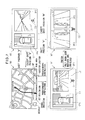
- FIG. 1 is a block diagram illustrating a configuration of an image display system 120 of an embodiment of the present invention.
- This image display system 120 is mounted on a vehicle (automobile in this embodiment) and it has a function to capture surroundings of the vehicle and generate images to display the images in a compartment.
- a user typically, a driver
- this image display system 120 can grasp circumstances around the vehicle substantially in real time.
- image display system 120 mainly comprises an image generation device 100 for generating a surrounding image that represent circumstances around the vehicle, and a navigation device 20 for displaying various types of information to the user driving the vehicle.
- the surrounding image generated by image generation device 100 is displayed by navigation device 20 .
- Navigation device 20 provides navigation guide for the user and it comprises a display 21 such as a liquid crystal display equipped with a touch panel function, a manipulation section 22 including hardware switches and the like manipulated by the user, and a control section 23 for controlling the overall device.
- Navigation device 20 is installed in an instrument panel and the like of the vehicle so that the user can view a screen of display 21 .
- Control section 23 is a computer comprising a CPU, RAM, ROM and the like, wherein the CPU performs arithmetic processing according to predetermined programs to implement various functions including the navigation function.
- Navigation device 20 is communicably connected to image generation device 100 so that it can transmit/receive various control signals to/from image generation device 100 and receive the images generated by image generation device 100 .
- a map image around the vehicle for navigation guide is displayed by the function of navigation device 20 only.
- the map image is stored in advance in a hard disk and the like provided in navigation device 20 .
- the position (latitude and longitude) of the vehicle is obtained by a GPS device provided in navigation device 20 and, based on the position of the vehicle, the map image around the vehicle is displayed on display 21 .
- a scale of the displayed map image can be changed by the user through manipulation section 22 .
- navigation device 20 also functions as a display device for receiving and displaying the surrounding image generated by image generation device 100 .
- Image generation device 100 comprises a main section 10 that is an ECU (Electronic Control Unit) having a function to generate an image, and a capture section 5 for generating images of circumstances around the vehicle.
- Main section 10 is disposed in a predetermined position in the vehicle and, based on the images of the circumstances around the vehicle obtained by capture section 5 , generates the surrounding image for displaying on display 21 .
- Capture section 5 is electrically connected to main section 10 and operates according to signals from main section 10 .
- Capture section 5 comprises a front camera 51 , side cameras 52 , and a back camera 53 , all of which are onboard cameras.
- Each of onboard cameras 51 - 53 comprises a lens and an imaging device and electronically obtains an image.
- FIG. 2 is a diagram illustrating the positions in which onboard cameras 51 - 53 are disposed in vehicle 9 .
- front camera 51 is mounted in the neighborhood of the position where a license plate is attached in a front end of vehicle 9 and an optical axis 51 a of front camera 51 is directed in a straight forward direction of vehicle 9 .
- Back camera 53 is mounted in the vicinity of where a license plate is attached to a back end of the vehicle 9 and an optical axis 53 a of back camera 53 is directed in a direction opposite to the straight forward direction of vehicle 9 . It is desirable that the attachment positions of front camera 51 and back camera 53 are located at the center in the left and right directions, but the attachment positions may deviate in the left or right direction to some extent.
- side cameras 52 are mounted on left and right side mirrors 93 one by one and the optical axis 52 a of side cameras 52 is directed to the outside of vehicle 9 along a left and right direction (a direction orthogonal to the straight forward direction) of vehicle 9 .
- onboard cameras 51 - 53 use wide-angle lenses such as fisheye lenses to have angular fields ⁇ of 180° or more. Onboard cameras can therefore capture images of the field of view extending obliquely below and above the respective optical axes. Capture section 5 uses four onboard cameras 51 - 53 so that the entire surroundings of the vehicle 9 can be imaged.
- main section 10 of image generation device 100 mainly comprises a control section 1 for controlling the entire device, an input terminal 49 for inputting the captured images from four onboard cameras 51 - 53 of capture section 5 , an image generation section 3 for generating the surrounding image to be displayed, and a navigation communication section 42 for communicating with navigation device 20 .
- image generation device 100 comprises a switch 43 for accepting an instruction to change the displayed contents from the user.
- the signals indicating the user's instructions are input to control section 1 also from this switch 43 .
- image generation device 100 can operate in response to the user's manipulation of both navigation device 20 and switch 43 .
- Switch 43 is disposed at a suitable position in the vehicle that is remote from the main section 10 such as, for example, at a position on a steering wheel or a center console in order to make it easy for the user to operate.
- Image generation section 3 is a hardware circuit that can perform various image processing operations, and it processes the captured images input from capture section 5 via input terminal 49 and generates a surrounding image to be displayed on display 21 .
- Image generation section 3 comprises, as main components, an image combination section 30 , a memory 31 , an image adjustment section 32 , a synthesized image generation section 34 , an image arrangement section 35 , and an indication addition section 36 .
- Image combination section 30 combines the captured images captured by capture section 5 into one combined image.
- FIGS. 3(A) and 3(B) are explanatory diagrams of a combined image Pcn generated by an image combining section 30 .
- front camera 51 , side cameras 52 and back camera 53 of capture section 5 perform imaging at the same time, four captured images P 1 -P 4 that represent circumstances in front, left-side, right-side and back directions of vehicle 9 are obtained.
- Image combination section 30 combines these four captured images P 1 -P 4 to generate a combined image Pcn as illustrated in FIG. 3(B) .
- Combined image Pcn generated by image combination section 30 is stored in memory 31 .
- Image adjustment section 32 performs adjustment so that combined image Pcn generated by image combination section 30 can be used for display. Specifically, with respect to captured images P 1 -P 4 included in combined image Pcn, image adjustment section 32 performs image processing operations such as distortion correction, enlargement and reduction and segmentation. Image adjustment section 32 comprises an image selection section 33 . In the segmentation process of captured images P 1 -P 4 included in combined image Pcn, image selection section 33 selects segmentation areas, in other words, areas to be displayed on display 21 .
- adjustment and setting values for the configuration are stored in a calibration (adjustment and configuration) process performed when the devices (cameras) are attached, and the image processing operations such as the adjustment operations and the like are performed by using these values.
- synthesized image generation section 34 Based on combined image Pcn, synthesized image generation section 34 generates a synthesized image that represents the circumstances around the vehicle from an arbitrary virtual viewpoint around the vehicle. The technique by which synthesized image generation section 34 generates the synthesized image will be described below.
- image arrangement section 35 arranges these images at predetermined display positions on the screen to generate the display image and output it to navigation device 20 .
- the surrounding image including at least a part of the circumstances around the vehicle is displayed on display 21 of navigation device 20 .
- the term “surrounding image” refers to an image including at least a part of the circumstances around the vehicle and it involves both the captured images adjusted to be displayed and the synthesized image.
- the captured images adjusted to be displayed are treated as the surrounding image from the field of view of the respective onboard cameras 51 - 53 which corresponds to a lens position of respective onboard camera 51 - 53 .
- the synthesized image is treated as the surrounding image from the virtual viewpoint disposed at an arbitrary position around the vehicle.
- Indication addition section 36 adds an indication, through which image display system 120 provides a predetermined information item to the user, to the display image generated by image arrangement section 35 .
- This indication may be, for example, an icon representing a particular information item or a character information item such as a message.
- indication addition section 36 adds an alarm indication (indicator) to a part of the display screen other than that where the synthesized image and the captured images are displayed.
- indication addition section 36 therefore functions as an indication emphasis section for emphasizing the alarm indication.
- Control section 1 is a computer comprising a CPU, RAM, ROM and the like, wherein the CPU performs arithmetic processing according to predetermined programs to implement various functions.
- An image control section 11 , a display control section 12 , an area selection section 13 , a preference determination section 14 , a detection signal receiving section 15 and an acceptance section 16 represent some of the functions of control section 1 implemented as described above.
- Image control section 11 performs control in connection with the image processing performed by image generation section 3 .
- image control section 11 indicates various parameters and the like that are required for generating the synthesized image by synthesized image generation section 34 .
- Display control section 12 performs control in connection with the contents displayed on display 21 of navigation device 20 .
- display control section 12 switches the contents displayed on display 21 according to the change of the operation mode of image display system 120 .
- Area selection section 13 selects the surrounding area to be shown to the user from a plurality of surrounding areas defined around the vehicle. When there are a plurality of surrounding areas to be shown to the user, preference determination section 14 determines their preference.
- Detection signal receiving section 15 receives detection signals described below to detect whether an obstacle exists within a predetermined area (around the vehicle) or not.
- Acceptance section 16 accepts an input to display an enlarged image that is an enlarged part representing the obstacle in the synthesized image on the display screen of navigation device 20 .
- Acceptance section 16 therefore functions as a switch indication section for indicating a switch image for instructing an enlarged indication when the obstacle is detected.
- display control section 12 displays the above enlarged image on the display screen of navigation device 20 instead of the synthesized image, as described below.
- display control section 12 When acceptance section 16 functioning as the switch indication section is manipulated, display control section 12 therefore functions as an enlargement indication section for indicating the enlarged image of the area where the obstacle is detected.
- Main section 10 of image generation device 100 further comprises a nonvolatile memory 40 , a card read section 44 , and a signal input section 41 , which are connected to control section 1 .
- Nonvolatile memory 40 is a flash memory and the like that can maintain the stored contents even while the power is turned off.
- a viewpoint data 4 a is stored in nonvolatile memory 40 .
- Viewpoint data 4 a is used to define the virtual viewpoint of the synthesized image.
- Card read section 44 reads a memory card MC that is a portable recording medium.
- Card read section 44 comprises a card slot into which memory card MC is removably attached and reads the data recorded in memory card MC that is inserted into the card slot.
- the data read by card read section 44 is input to control section 1 .
- Memory card MC is a flash memory and the like that can store various data and image generation device 100 can use the various data stored in memory card MC.
- a program (firmware) for implementing the functions of control section 1 can be updated by writing the program in memory card MC and reading it.
- signal input section 41 input signals from various devices provided in the vehicle. Through this signal input section 41 , signals from the outside of image display system 120 are input to control section 1 . In this embodiment, signals from a sonar system 7 and a shift lever sensor 8 are input to control section 1 via signal input section 41 .
- a detection result including the position of the obstacle and the distance between the vehicle and the obstacle is input.
- the shift lever sensor 8 From the shift lever sensor 8 , the position to which a shift lever of a gear box of the vehicle is moved, in other words, the shift position such as “P (parking)”, “D (drive)”, “N (neutral)”, “R (reverse)” and the like is input.
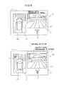
- FIG. 4 is a diagram mainly illustrating a configuration of sonar system 7 .
- sonar system 7 comprises sonar control section 70 for controlling the entire system, a plurality of clearance sonar devices 72 , and a buzzer 71 for raising an alarm in the vehicle.
- Each of clearance sonar devices 72 transmits an ultrasound wave and receives a reflected wave that is the ultrasound wave reflected by the obstacle to detect the obstacle existing around the vehicle. Further, clearance sonar device 72 can measure a distance between the vehicle and the obstacle based on a time from the transmission of the ultrasonic wave to the reception of the same.
- the detection results of clearance sonar devices 72 are input to sonar control section 70 , so that buzzer 71 raises an alarm according to the distance between the vehicle and the obstacle. As a result, the user can grasp whether an obstacle exists or not around the vehicle.
- FIG. 5 is a diagram illustrating positions at which a plurality of clearance sonar devices 72 are placed on vehicle 9 .
- the plurality of clearance sonar devices 72 are provided at the front left and right ends of vehicle 9 and at the back left and right ends of vehicle 9 .
- Each clearance sonar device 72 transmits an ultrasonic wave to surrounding areas A 1 -A 4 which are some of the circumstances around vehicle 9 .
- clearance sonar device 72 provided at the front left end of vehicle 9 transmits an ultrasonic wave to the surrounding area A 1 defined in the front left side (“front left area”) of vehicle 9 .
- clearance sonar device 72 provided at the front right end of vehicle 9 transmits an ultrasonic wave to the surrounding area A 2 defined in the front right side (“front right area”) of vehicle 9 .
- clearance sonar device 72 provided at the back left end of vehicle 9 transmits an ultrasonic wave to the surrounding area A 3 defined in the back left side (“back left area”) of vehicle 9 .
- clearance sonar device 72 provided at the back right end of vehicle 9 transmits an ultrasonic wave to the surrounding area A 4 defined in the back right side (“back right area”) of vehicle 9 .
- sonar system 7 can detect the obstacle existing in four surrounding areas A 1 -A 4 . Based on the position of clearance sonar device 72 that detected the obstacle, sonar system 7 can grasp in which one of surrounding areas A 1 -A 4 the detected obstacle is located. Further, sonar system 7 can measure the distance between the vehicle and the obstacle.
- the detection result of sonar system 7 including the position of the obstacle and the distance between the vehicle and the obstacle is input from sonar control section 70 to control section 1 of image generation device 100 via signal input section 41 . Then, this detection result of sonar system 7 is used by detection signal receiving section 15 of control section 1 and the like.
- FIG. 6 is a diagram for describing the technique for generating the synthesized image.
- a combined image Pen in which the four captured images P 1 -P 4 captured by captured section 5 are combined with each other includes information about an entire circumstance around vehicle 9 at the time of capture.
- each of pixels of combined image Pcn is projected to a three-dimensional curved surface TS in a virtual three-dimensional space.
- three-dimensional curved surface TS has a substantially hemispherical shape (bowilike shape) and its center (bottom of the bowl) is defined as a position at which vehicle 9 is positioned.
- each of pixel values in three-dimensional surface TS can be determined based on this relationship and each of pixel values included in combined image Pcn.
- each of the positions of the pixels in combined image Pcn and each of the positions of the pixels in this three-dimensional curved surface TS depends on arrangement (distances between each other, height above ground level, optical axis angle and the like) of four onboard cameras 51 - 53 in vehicle 9 .
- a table data representing this relationship is stored in nonvolatile memory 40 in advance.
- a data indicating a shape and size of the vehicle body stored in nonvolatile memory 40 in advance is used to virtually construct a polygon model representing a three-dimensional shape of vehicle 9 .
- the constructed model of vehicle 9 is positioned at the center of the substantially semispherical shape, which is defined as the position of vehicle 9 , in the three-dimensional space in which three-dimensional curved surface TS is defined.
- control section 1 defines virtual viewpoint VP.
- Virtual viewpoint VP is defined by a viewpoint position and a field-of-view direction and it is defined at an arbitrary viewpoint position corresponding to the surroundings of vehicle 9 in this three-dimensional space in an arbitrary field-of-view direction.
- a necessary area in three-dimensional curved surface TS is cut out as an image according to the defined virtual viewpoint VP.
- a relationship between virtual viewpoint VP and a necessary area in three-dimensional curved surface TS is predefined and stored as a table data in nonvolatile memory 40 and the like in advance.
- the polygon model is rendered according to the defined virtual viewpoint VP and the resultant two-dimensional image of the vehicle is superimposed on the cut out image. As a result, a synthesized image representing vehicle 9 and the surroundings thereof viewed from the arbitrary virtual viewpoint VP is generated.
- a virtual viewpoint VPa whose viewpoint position is substantially just above the center of the position of vehicle 9 and whose field of view is directed to just below
- a synthesized image CPa representing vehicle 9 and the surroundings thereof that are seen when vehicle 9 is looked down substantially from just above vehicle 9
- a virtual viewpoint VPb whose viewpoint is positioned at a left back side of vehicle 9 and whose field of view is directed substantially to a forward side of vehicle 9
- a synthesized image CPb representing vehicle 9 and the surroundings thereof that is seen when the surroundings are viewed from the left back side of vehicle 9 .
- synthesized image generation section 34 When the synthesized image is actually generated, it is not necessary to determine all pixel values of three-dimensional curved surface TS. Rather, it is possible to determine only pixel values of an area required in accordance with the defined virtual viewpoint VP, based on captured images P 1 - 24 , so that processing speed can be increased.
- image display system 120 the functions of synthesized image generation section 34 described above are used to generate a synthesized image viewed from an arbitrary viewpoint around vehicle 9 and display it on display 21 .
- FIG. 7 is a diagram illustrating transition of operation modes of image display system 120 .
- Image display system 120 has a navigation mode M 0 and three operation modes including a front mode M 1 , a side mode M 2 and a back mode M 3 . These operation modes can be switched under the control of control section 1 according to handling of vehicle 9 by the driver and a running state of vehicle 9 .
- Navigation mode M 0 is an operation mode in which the functions of navigation device 20 is used to provide navigation guide.
- the functions of image generation device 100 are not used and various indications are displayed on display 21 by the functions of navigation device 20 only. Specifically, a map image NP around vehicle 9 is mainly displayed on display 21 .
- front mode M 1 , side mode M 2 and back mode M 3 are operation modes in which the functions of image generation device 100 is used to display the surrounding image on display 21 to show the circumstances around the vehicle to the user in real time.
- Front mode M 1 is an operation mode that indicates the forward side of vehicle 9 and is used when the vehicle enters into a crossing with bad visibility and the like.
- a captured image hereinafter referred to as a “front image”
- This front image SP 1 is a surrounding image viewed from the viewpoint at the front side of vehicle 9 (the lens position of front camera 51 ).
- an icon C 1 is displayed to indicate that the surrounding image (i.e., front image) SP 1 that is being displayed is the scene in the front side of vehicle 9 .
- synthesized image CPa that represents vehicle 9 and the surroundings thereof, with are seen when vehicle 9 is looked down substantially from just above vehicle 9 , and that is generated by synthesized image generation section 34 , are indicated.
- Side mode M 2 is an operation mode that indicates the lateral side of vehicle 9 and is used when the vehicle is pulled over to the side of the road and the like.
- a third indication position L 3 and a fourth indication position L 4 of display 21 captured images (hereinafter referred to as “side images”) SP 2 that are captured by side cameras 52 and adjusted for indication are displayed.
- side images SP 2 are surrounding images viewed from the viewpoints at the lateral sides of vehicle 9 (the lens positions of front cameras 52 ). In this mode, the vehicle is or will be going forward (except the shift position “R”). In side images SP 2 , therefore, the circumstances in the forward direction from the lateral side images of the vehicle are cut out.
- Side images SP 2 include portions of the vehicle body so that a relationship between the vehicle body and a road (and objects outside the vehicle) can be readily seen.
- Image processing (cut out, rotation and the like) is performed on side image SP 2 so that the travelling direction of the vehicle substantially corresponds to the vertical direction.
- an icon C 2 is displayed to indicate that the surrounding images (i.e., side images) SP 2 that are being displayed are the scenes in the lateral sides of vehicle 9 .
- back mode M 3 is an operation mode that indicates the back side of vehicle 9 and is used when the vehicle goes back.
- a captured image hereinafter referred to as a “back image”
- This back image SP 3 is a surrounding image viewed from the viewpoint at the back side of vehicle 9 (the lens position of back camera 53 ).
- an icon C 3 is displayed to indicate that the surrounding image (i.e., back image) SP 3 that is being displayed is the scene in the back side of vehicle 9 .
- synthesized image CPa that is generated by synthesized image generation section 34 to indicate vehicle 9 and surrounding area thereof, which are seen when vehicle 9 is looked down substantially from just above vehicle 9 , is displayed.
- navigation mode M 0 when manipulation section 22 of navigation device 20 is manipulated in a predetermined manner (to indicate the surrounding image), navigation mode M 0 is switched to one of front mode M 1 and side mode M 2 that has been lastly validated (so called a last mode). Front mode M 1 and Side mode M 2 can be switched to each other by pushing switch 43 once. Further, in front mode M 1 or side mode M 2 , when manipulation section 22 of navigation device 20 is manipulated in a predetermined manner, the operation mode returns to navigation mode M 0 .
- any operation mode other than back mode M 3 when the “R (reverse)” shift position is input from shift sensor 71 , the operation mode is switched to back mode M 3 .
- the operation mode is switched to back mode M 3 that mainly indicate the circumstances in the back side of vehicle 9 .
- back mode M 3 when any shift position other than the “R (reverse)” is input, the operation mode returns to the operation mode immediately before it is switched to back mode M 3 .
- image display system 120 can display the surrounding image from a plurality of viewpoints in a switchable manner by switching a plurality of operation modes.
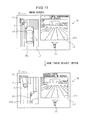
- FIG. 8 is an explanatory diagram of an example of addition of alarm indication.
- a message “Directly check surroundings of vehicle” is added by indication addition section 36 . This message is indicated while the surrounding image of the vehicle is indicated regardless of the detection state of the obstacle by sonar system 7 .
- detection signal receiving section 15 detects that obstacle S exists around vehicle 9 . At this time, obstacle S is captured by the camera and seen in synthesized image CPa. Indication addition section 36 further adds a frame F surrounding the massage (caution text) “Directly check surroundings of vehicle” as the alarm indication.
- Indication addition section 36 changes color of frame F according to the distance between vehicle 9 and obstacle. For example, when the distance between vehicle 9 and obstacle S is 0 cm or more and less than 25 cm, frame F is colored in a first color (for example, red); when the distance between vehicle 9 and obstacle S is 25 cm or more and less than 150 cm, frame F is colored in a second color (for example, yellow); and when the distance between vehicle 9 and obstacle S is 150 cm or more, frame F is colored in a third color (for example, green). At this time, not only the color of frame F but also the color of the text and background may be changed according to the distance between vehicle 9 and obstacle S.
- a first color for example, red
- second color for example, yellow
- a third color for example, green
- the text information such as the message and the frame surrounding the text information may be indicated at any position except the synthesized image CPa and front image SP 1 on the screen of display 21 .
- the indication state (color) of frame F as the alarm indication is changed according to the detection state of obstacle S or the distance between vehicle 9 and obstacle S, so that the existence of the obstacle and a sense of distance between the vehicle and the obstacle can be recognized intuitively without hiding the surrounding image of synthesized image CPa and front image SP 1 .
- the location of the obstacle therefore can be checked easily from the surrounding image of synthesized image CPa while calling attention to the obstacle.
- the message is emphasized by frame F without hiding the surrounding image of synthesized image CPa and front image SP 1 , so that the existence of obstacle S around vehicle 9 can be recognized and better understood by the text alarm indication.
- FIG. 9 is an explanatory diagram of another example of addition of alarm indication.
- a message “Directly check surroundings of vehicle” is added by indication addition section 36 . But, this message may not be added.
- detection signal receiving section 15 detects that obstacle S exists around vehicle 9 .
- obstacle S is captured by the camera and seen in synthesized image CPa.
- Indication addition section 36 further indicates an L-shaped indicator I 1 at the corner on a circumference (outside the image area) of synthesized image CPa in a direction of the obstacle and an indicator I 2 of a small round shape and the like at the corner on a circumference of vehicle 9 in a direction of the obstacle as the alarm indication.
- These indicators are displayed on an area of the screen of display 21 , except synthesized image CPa and front image SP 1 and on an area of vehicle 9 in synthesized image CPa (the image captured by the camera is not hidden).
- Indication addition section 36 changes color of indicators I 1 , I 2 according to the distance between vehicle 9 and obstacle S. For example, when the distance between vehicle 9 and obstacle S is 0 cm or more and less than 25 cm, indicators I 1 , I 2 are colored in a first color (for example, red); when the distance between vehicle 9 and obstacle S is 25 cm or more and less than 150 cm, indicators I 1 , I 2 are colored in a second color (for example, yellow); and when the distance between vehicle 9 and obstacle S is 150 cm or more, indicators I 1 , I 2 are colored in a third color (for example, green).
- a first color for example, red
- a second color for example, yellow
- a third color for example, green
- the indicator may be added to the periphery of synthesized image CPa.
- the indicator I 1 ′ may be added to a surrounding area of synthesized image CPa or the indicator I 2 ′ may be added to an area in the synthesized image along the surrounding area of synthesized image CPa.
- the indicator may be added to at least one of the area of the screen of display 21 except synthesized image CPa and front image SP 1 and an area of vehicle 9 in synthesized image CPa.
- indicators I 1 , I 2 in a first color for example, red
- indicator I 1 in a second color for example, yellow
- indicator I 1 in a third color for example, green
- the alarm indication by means of frame F as illustrated in FIG. 8 may be used in combination with at least one of indicator I 1 and indicator I 2 .
- the indication state (color) of indicators I 1 , I 2 as the alarm indication is changed according to the detection state of obstacle S or the distance between vehicle 9 and obstacle S, so that the existence of the obstacle and a sense of distance between the vehicle and the obstacle can be recognized intuitively without hiding the surrounding image of synthesized image CPa and front image SP 1 .
- the location of the obstacle therefore can be checked easily from the surrounding image of synthesized image CPa while calling attention to the obstacle.
- indicator I 1 when obstacle S is located in the distance, for example, when the distance between vehicle 9 and obstacle S is 50 cm or more, indicator I 1 only may be added and, when obstacle S is located in the neighborhood, for example, when the distance between vehicle 9 and obstacle S is less than 50 cm, both indicators I 1 and I 2 may be added (indication which represents obstacles S sandwiched between indicator I 1 and indicator I 2 ), so that the attention to obstacle S can be enhanced.
- FIG. 11 is an explanatory diagram of enlargement of a synthesized image.
- a message “Directly check surroundings of vehicle” is added by indication addition section 36 and, on the message “Directly check surroundings of vehicle”, there is indicated a “Check details” switch for allowing acceptance section 16 to accept an input to enlarge a part showing obstacle S in synthesized image CPa and indicate it as an enlarged image CPa′ on display 21 .
- FIG. 12 a process of image display system 120 to add the alarm indication will be described.
- at least one of indicators I 1 and I 2 are added as illustrated in FIGS. 9 and 11 , and the “Check details” switch is indicated as illustrated in FIG. 11 .
- This process is performed repeatedly during the operation of image display system 120 .
- the similar process is performed when frame F illustrated in FIG. 8 is added as the alarm indication.
- onboard cameras 51 - 53 capture respective captured images P 1 -P 4 .
- image combination section 30 generates combined image Pcn in which images P 1 -P 4 are combined with each other and stores it in memory 31 .
- synthesized image generation section 34 generates synthesized image CPa based on combined image Pcn.
- image arrangement section 35 selects any of synthesized image CPa and captured images SP 1 -SP 3 and arranges it on the display image to be output to navigation device 20 .
- the image to be displayed is output to navigation device 20 by image generation device 100 .
- navigation device 20 indicates the display image output from image generation device 100 on display 21 .
- sonar system 7 determines whether the obstacle around vehicle 9 is detected or not.
- indication addition section 36 adds at least one of indicator I 1 and indicator I 2 as the alarm indication to the screen of display 21 .
- acceptance section 16 determines whether the “Check details” switch is pushed or not.
- display control section 12 indicates enlarged image CPa′ on the screen of display 21 in place of synthesized image CPa.
Landscapes
- Engineering & Computer Science (AREA)
- Multimedia (AREA)
- Physics & Mathematics (AREA)
- General Physics & Mathematics (AREA)
- Mechanical Engineering (AREA)
- Closed-Circuit Television Systems (AREA)
- Traffic Control Systems (AREA)
Abstract
An image display system including a synthesized image generation section that generates a synthesized image representing a vehicle and circumstances around the vehicle viewed from a virtual viewpoint based on captured images obtained by cameras disposed on the vehicle, a navigation device that displays the synthesized image and the captured images on a display screen, an obstacle detection section that detects an obstacle, and an indication addition section that, when the obstacle is detected, adds an alarm indication to call attention to at least one of an area of the display screen except the synthesized image, and a surrounding area of the synthesized image is provided.
Description
- This application is a new U.S. patent application that claims priorities to Japanese Application No. 2011-080742, filed on Mar. 31, 2011, the content of which is incorporated herein by reference.
- The present invention relates to a technique for displaying an image in a vehicle.
- Conventionally, an image display system that is mounted in a vehicle such as an automobile and that displays a surrounding image around the vehicle based on captured images obtained by onboard cameras on a display in a compartment is known. A user (typically, driver) can use this image display system to see the area around the vehicle in real time.
- For example, an area outside of a front fender opposite the driver's seat may be a blind spot and it is difficult for the user to see clearance between the vehicle body and an obstacle. In contrast, the image display system can be used to display the surrounding image of the area outside the front fender, which is generated based on the captured images obtained by the onboard cameras disposed in the lateral sides of the vehicle, on the display in the compartment. As a result, when the vehicle is pulled over to the side of the road, etc., the user can easily check the clearance between the vehicle body and an obstacle on the opposite side of the driver's seat.
- Further, an image display system that indicates a position where the obstacle exists (for example, Patent Document 1) is known. In this image display system, an alarm indication is added to the image around the vehicle (the “surrounding image”).
-
- Patent Document 1: JP-2007-180622-A
- When the image display system calls attention, the user uses the surrounding image to check where the obstacle exists. However, in the image display system described above, the alarm indication may hide the surrounding image and, as a result, it may be difficult to check if an obstacle exists from the surrounding image.
- It is an object of the present invention to provide an image display system that allows easily determining where an obstacle exists from a surrounding image while calling attention.
- An image display system mounted on a vehicle, including a synthesized image generation section that generates a synthesized image representing the vehicle and circumstances around the vehicle viewed from a virtual viewpoint based on captured images obtained by cameras disposed on the vehicle, a display section that displays the synthesized image and the captured images on a display screen, an obstacle detection section that detects an obstacle, and an indication addition section that, when the obstacle is detected, adds an alarm indication to call attention to at least one of an area of the display screen except the synthesized image and the captured images, a surrounding area of the synthesized image, and an area of the vehicle in the synthesized image is provided.
- An image generation device including a synthesized image generation section that generates a synthesized image representing circumstances viewed from a virtual viewpoint based on captured images, a display section that displays the synthesized image and the captured images on a display screen of a display device,
- a detection signal receiving section that receives a detection signal from an obstacle detection section detecting an obstacle, and an indication addition section that, when the obstacle is detected, adds an alarm indication to call attention to at least one of an area of the display screen except the synthesized image and the captured images, a surrounding area of the synthesized image, and an area of the vehicle in the synthesized image is provided.
- An image display method including the steps of generating a synthesized image representing the vehicle and circumstances around the vehicle viewed from a virtual viewpoint based on captured images obtained by cameras disposed on the vehicle; displaying the synthesized image and the captured images on a display screen, detecting whether an obstacle exists or not; and, when the obstacle is detected, adding an alarm indication to call attention to at least one of an area of the display screen except the synthesized image and the captured images, a surrounding area of the synthesized image, and an area of the vehicle in the synthesized image is provided.
- According to the above image display system, image generation device or image display method, it is easy to determine if an obstacle exists from a surrounding image while calling attention.
- These and other features and advantages of the present invention will be better understood by reading the following detailed description, taken together with the drawings wherein:
-
FIG. 1 is a diagram illustrating an exemplary configuration of an image display system of an embodiment of the present invention; -
FIG. 2 is a diagram illustrating positions in which onboard cameras are placed; -
FIGS. 3(A) and 3(B) are explanatory diagrams of a combined image generated by an image combining section; -
FIG. 4 is a diagram mainly illustrating a configuration of a sonar system; -
FIG. 5 is a diagram illustrating positions on a vehicle at which clearance sonar devices are placed; -
FIG. 6 is a diagram for describing a technique for generating a synthesized image; -
FIG. 7 is a diagram illustrating transition of operation modes of the image display system; -
FIG. 8 is an explanatory diagram of an example of addition of an alarm indication; -
FIG. 9 is an explanatory diagram of another example of addition of an alarm indication; -
FIG. 10 is an explanatory diagram of a variation of an indicator; -
FIG. 11 is an explanatory diagram of enlargement of a synthesized image; and -
FIG. 12 is an explanatory diagram of an exemplary process of an image display system. -
FIG. 1 is a block diagram illustrating a configuration of animage display system 120 of an embodiment of the present invention. Thisimage display system 120 is mounted on a vehicle (automobile in this embodiment) and it has a function to capture surroundings of the vehicle and generate images to display the images in a compartment. A user (typically, a driver) can use thisimage display system 120 to grasp circumstances around the vehicle substantially in real time. - As illustrated in
FIG. 1 ,image display system 120 mainly comprises animage generation device 100 for generating a surrounding image that represent circumstances around the vehicle, and a navigation device 20 for displaying various types of information to the user driving the vehicle. The surrounding image generated byimage generation device 100 is displayed by navigation device 20. - Navigation device 20 provides navigation guide for the user and it comprises a
display 21 such as a liquid crystal display equipped with a touch panel function, a manipulation section 22 including hardware switches and the like manipulated by the user, and acontrol section 23 for controlling the overall device. Navigation device 20 is installed in an instrument panel and the like of the vehicle so that the user can view a screen ofdisplay 21. - Various instructions of the user are accepted by manipulation section 22 and display 21 as a touch panel.
Control section 23 is a computer comprising a CPU, RAM, ROM and the like, wherein the CPU performs arithmetic processing according to predetermined programs to implement various functions including the navigation function. Navigation device 20 is communicably connected toimage generation device 100 so that it can transmit/receive various control signals to/fromimage generation device 100 and receive the images generated byimage generation device 100. - On
display 21, according to the control ofcontrol section 23, usually, a map image around the vehicle for navigation guide is displayed by the function of navigation device 20 only. The map image is stored in advance in a hard disk and the like provided in navigation device 20. Further, the position (latitude and longitude) of the vehicle is obtained by a GPS device provided in navigation device 20 and, based on the position of the vehicle, the map image around the vehicle is displayed ondisplay 21. A scale of the displayed map image can be changed by the user through manipulation section 22. - On the other hand, when the operation mode of
image display system 120 is changed, the surrounding image around the vehicle generated byimage generation device 100 is displayed ondisplay 21. As a result, navigation device 20 also functions as a display device for receiving and displaying the surrounding image generated byimage generation device 100. -
Image generation device 100 comprises amain section 10 that is an ECU (Electronic Control Unit) having a function to generate an image, and a capture section 5 for generating images of circumstances around the vehicle.Main section 10 is disposed in a predetermined position in the vehicle and, based on the images of the circumstances around the vehicle obtained by capture section 5, generates the surrounding image for displaying ondisplay 21. - Capture section 5 is electrically connected to
main section 10 and operates according to signals frommain section 10. Capture section 5 comprises afront camera 51,side cameras 52, and aback camera 53, all of which are onboard cameras. Each of onboard cameras 51-53 comprises a lens and an imaging device and electronically obtains an image. - A plurality of onboard cameras 51-53 are disposed in positions different from each other of the vehicle.
FIG. 2 is a diagram illustrating the positions in which onboard cameras 51-53 are disposed invehicle 9. - As illustrated in
FIG. 2 ,front camera 51 is mounted in the neighborhood of the position where a license plate is attached in a front end ofvehicle 9 and anoptical axis 51 a offront camera 51 is directed in a straight forward direction ofvehicle 9.Back camera 53 is mounted in the vicinity of where a license plate is attached to a back end of thevehicle 9 and anoptical axis 53 a ofback camera 53 is directed in a direction opposite to the straight forward direction ofvehicle 9. It is desirable that the attachment positions offront camera 51 andback camera 53 are located at the center in the left and right directions, but the attachment positions may deviate in the left or right direction to some extent. On the other hand,side cameras 52 are mounted on left andright side mirrors 93 one by one and theoptical axis 52 a ofside cameras 52 is directed to the outside ofvehicle 9 along a left and right direction (a direction orthogonal to the straight forward direction) ofvehicle 9. - These onboard cameras 51-53 use wide-angle lenses such as fisheye lenses to have angular fields θ of 180° or more. Onboard cameras can therefore capture images of the field of view extending obliquely below and above the respective optical axes. Capture section 5 uses four onboard cameras 51-53 so that the entire surroundings of the
vehicle 9 can be imaged. - Returning to
FIG. 1 ,main section 10 ofimage generation device 100 mainly comprises acontrol section 1 for controlling the entire device, aninput terminal 49 for inputting the captured images from four onboard cameras 51-53 of capture section 5, an image generation section 3 for generating the surrounding image to be displayed, and anavigation communication section 42 for communicating with navigation device 20. - Various instructions from the user accepted by manipulation section 22 of navigation device 20 or
display 21 are accepted bynavigation communication section 42 as control signals and input to controlsection 10. Further,image generation device 100 comprises a switch 43 for accepting an instruction to change the displayed contents from the user. The signals indicating the user's instructions are input to controlsection 1 also from this switch 43. Thus,image generation device 100 can operate in response to the user's manipulation of both navigation device 20 and switch 43. Switch 43 is disposed at a suitable position in the vehicle that is remote from themain section 10 such as, for example, at a position on a steering wheel or a center console in order to make it easy for the user to operate. - Image generation section 3 is a hardware circuit that can perform various image processing operations, and it processes the captured images input from capture section 5 via
input terminal 49 and generates a surrounding image to be displayed ondisplay 21. Image generation section 3 comprises, as main components, animage combination section 30, amemory 31, animage adjustment section 32, a synthesizedimage generation section 34, animage arrangement section 35, and anindication addition section 36. -
Image combination section 30 combines the captured images captured by capture section 5 into one combined image.FIGS. 3(A) and 3(B) are explanatory diagrams of a combined image Pcn generated by animage combining section 30. Whenfront camera 51,side cameras 52 and backcamera 53 of capture section 5 perform imaging at the same time, four captured images P1-P4 that represent circumstances in front, left-side, right-side and back directions ofvehicle 9 are obtained.Image combination section 30 combines these four captured images P1-P4 to generate a combined image Pcn as illustrated inFIG. 3(B) . Combined image Pcn generated byimage combination section 30 is stored inmemory 31. -
Image adjustment section 32 performs adjustment so that combined image Pcn generated byimage combination section 30 can be used for display. Specifically, with respect to captured images P1-P4 included in combined image Pcn,image adjustment section 32 performs image processing operations such as distortion correction, enlargement and reduction and segmentation.Image adjustment section 32 comprises animage selection section 33. In the segmentation process of captured images P1-P4 included in combined image Pcn,image selection section 33 selects segmentation areas, in other words, areas to be displayed ondisplay 21. In order to configure segmentation settings (setting of the segmentation areas), enlargement and reduction settings and the like, adjustment and setting values for the configuration are stored in a calibration (adjustment and configuration) process performed when the devices (cameras) are attached, and the image processing operations such as the adjustment operations and the like are performed by using these values. - Based on combined image Pcn, synthesized
image generation section 34 generates a synthesized image that represents the circumstances around the vehicle from an arbitrary virtual viewpoint around the vehicle. The technique by which synthesizedimage generation section 34 generates the synthesized image will be described below. - The captured images that are adjusted to be displayed by
image adjustment section 32 and the synthesized image generated by synthesizedimage generation section 34 are output to navigation device 20 bynavigation communication section 42. At this time, according to the operation mode ofimage display system 120 described below,image arrangement section 35 arranges these images at predetermined display positions on the screen to generate the display image and output it to navigation device 20. As a result, the surrounding image including at least a part of the circumstances around the vehicle is displayed ondisplay 21 of navigation device 20. - In this patent specification, the term “surrounding image” refers to an image including at least a part of the circumstances around the vehicle and it involves both the captured images adjusted to be displayed and the synthesized image. The captured images adjusted to be displayed are treated as the surrounding image from the field of view of the respective onboard cameras 51-53 which corresponds to a lens position of respective onboard camera 51-53. Further, the synthesized image is treated as the surrounding image from the virtual viewpoint disposed at an arbitrary position around the vehicle.
-
Indication addition section 36 adds an indication, through whichimage display system 120 provides a predetermined information item to the user, to the display image generated byimage arrangement section 35. This indication may be, for example, an icon representing a particular information item or a character information item such as a message. Further, as described below, when an obstacle is detected,indication addition section 36 adds an alarm indication (indicator) to a part of the display screen other than that where the synthesized image and the captured images are displayed. When the obstacle is detected,indication addition section 36 therefore functions as an indication emphasis section for emphasizing the alarm indication. -
Control section 1 is a computer comprising a CPU, RAM, ROM and the like, wherein the CPU performs arithmetic processing according to predetermined programs to implement various functions. Animage control section 11, adisplay control section 12, anarea selection section 13, apreference determination section 14, a detectionsignal receiving section 15 and anacceptance section 16 represent some of the functions ofcontrol section 1 implemented as described above. -
Image control section 11 performs control in connection with the image processing performed by image generation section 3. For example,image control section 11 indicates various parameters and the like that are required for generating the synthesized image by synthesizedimage generation section 34. -
Display control section 12 performs control in connection with the contents displayed ondisplay 21 of navigation device 20. For example,display control section 12 switches the contents displayed ondisplay 21 according to the change of the operation mode ofimage display system 120. -
Area selection section 13 selects the surrounding area to be shown to the user from a plurality of surrounding areas defined around the vehicle. When there are a plurality of surrounding areas to be shown to the user,preference determination section 14 determines their preference. - Detection
signal receiving section 15 receives detection signals described below to detect whether an obstacle exists within a predetermined area (around the vehicle) or not.Acceptance section 16 accepts an input to display an enlarged image that is an enlarged part representing the obstacle in the synthesized image on the display screen of navigation device 20.Acceptance section 16 therefore functions as a switch indication section for indicating a switch image for instructing an enlarged indication when the obstacle is detected. Onceacceptance section 16 accepts the above input,display control section 12 displays the above enlarged image on the display screen of navigation device 20 instead of the synthesized image, as described below. Whenacceptance section 16 functioning as the switch indication section is manipulated,display control section 12 therefore functions as an enlargement indication section for indicating the enlarged image of the area where the obstacle is detected. -
Main section 10 ofimage generation device 100 further comprises anonvolatile memory 40, a card readsection 44, and asignal input section 41, which are connected to controlsection 1. -
Nonvolatile memory 40 is a flash memory and the like that can maintain the stored contents even while the power is turned off. Innonvolatile memory 40, aviewpoint data 4 a is stored.Viewpoint data 4 a is used to define the virtual viewpoint of the synthesized image. - Card read
section 44 reads a memory card MC that is a portable recording medium. Card readsection 44 comprises a card slot into which memory card MC is removably attached and reads the data recorded in memory card MC that is inserted into the card slot. The data read by card readsection 44 is input to controlsection 1. Memory card MC is a flash memory and the like that can store various data andimage generation device 100 can use the various data stored in memory card MC. For example, a program (firmware) for implementing the functions ofcontrol section 1 can be updated by writing the program in memory card MC and reading it. - Further, signal
input section 41 input signals from various devices provided in the vehicle. Through thissignal input section 41, signals from the outside ofimage display system 120 are input to controlsection 1. In this embodiment, signals from asonar system 7 and ashift lever sensor 8 are input to controlsection 1 viasignal input section 41. - As described below, from
sonar system 7 as an obstacle detection section, a detection result including the position of the obstacle and the distance between the vehicle and the obstacle is input. From theshift lever sensor 8, the position to which a shift lever of a gear box of the vehicle is moved, in other words, the shift position such as “P (parking)”, “D (drive)”, “N (neutral)”, “R (reverse)” and the like is input. -
FIG. 4 is a diagram mainly illustrating a configuration ofsonar system 7. As illustrated inFIG. 4 ,sonar system 7 comprisessonar control section 70 for controlling the entire system, a plurality ofclearance sonar devices 72, and abuzzer 71 for raising an alarm in the vehicle. - Each of
clearance sonar devices 72 transmits an ultrasound wave and receives a reflected wave that is the ultrasound wave reflected by the obstacle to detect the obstacle existing around the vehicle. Further,clearance sonar device 72 can measure a distance between the vehicle and the obstacle based on a time from the transmission of the ultrasonic wave to the reception of the same. - The detection results of
clearance sonar devices 72 are input tosonar control section 70, so thatbuzzer 71 raises an alarm according to the distance between the vehicle and the obstacle. As a result, the user can grasp whether an obstacle exists or not around the vehicle. -
FIG. 5 is a diagram illustrating positions at which a plurality ofclearance sonar devices 72 are placed onvehicle 9. The plurality ofclearance sonar devices 72 are provided at the front left and right ends ofvehicle 9 and at the back left and right ends ofvehicle 9. - Each
clearance sonar device 72 transmits an ultrasonic wave to surrounding areas A1-A4 which are some of the circumstances aroundvehicle 9. Specifically,clearance sonar device 72 provided at the front left end ofvehicle 9 transmits an ultrasonic wave to the surrounding area A1 defined in the front left side (“front left area”) ofvehicle 9. Further,clearance sonar device 72 provided at the front right end ofvehicle 9 transmits an ultrasonic wave to the surrounding area A2 defined in the front right side (“front right area”) ofvehicle 9. Further,clearance sonar device 72 provided at the back left end ofvehicle 9 transmits an ultrasonic wave to the surrounding area A3 defined in the back left side (“back left area”) ofvehicle 9. Further,clearance sonar device 72 provided at the back right end ofvehicle 9 transmits an ultrasonic wave to the surrounding area A4 defined in the back right side (“back right area”) ofvehicle 9. - These four surrounding areas A1-A4 are defined in advance fixedly in relation to
vehicle 9. As a result of this arrangement ofclearance sonar devices 72,sonar system 7 can detect the obstacle existing in four surrounding areas A1-A4. Based on the position ofclearance sonar device 72 that detected the obstacle,sonar system 7 can grasp in which one of surrounding areas A1-A4 the detected obstacle is located. Further,sonar system 7 can measure the distance between the vehicle and the obstacle. - As illustrated in
FIG. 4 , the detection result ofsonar system 7 including the position of the obstacle and the distance between the vehicle and the obstacle is input fromsonar control section 70 to controlsection 1 ofimage generation device 100 viasignal input section 41. Then, this detection result ofsonar system 7 is used by detectionsignal receiving section 15 ofcontrol section 1 and the like. - Next, there will be described a technique in which synthesized
image generation section 34 of image generation section 3 generates a synthesized image that representsvehicle 9 itself and circumstances aroundvehicle 9 viewed from an arbitrary virtual viewpoint based on the plurality of captured images 91-94 obtained by capture section 5.FIG. 6 is a diagram for describing the technique for generating the synthesized image. - As described above, when
front camera 51,side cameras 52 and backcamera 53 of capture section 5 capture images at the same time, four captured images P1-P4 that represent circumstances in the front, left-side, right-side and back directions ofvehicle 9, respectively, are obtained. A combined image Pen in which the four captured images P1-P4 captured by captured section 5 are combined with each other includes information about an entire circumstance aroundvehicle 9 at the time of capture. - Next, each of pixels of combined image Pcn is projected to a three-dimensional curved surface TS in a virtual three-dimensional space. For example, three-dimensional curved surface TS has a substantially hemispherical shape (bowilike shape) and its center (bottom of the bowl) is defined as a position at which
vehicle 9 is positioned. There is established in advance a relationship between a position of each of the pixels in combined image Pcn and a position of each of the pixels in this three-dimensional curved surface TS. As a result, each of pixel values in three-dimensional surface TS can be determined based on this relationship and each of pixel values included in combined image Pcn. - The relationship between each of the positions of the pixels in combined image Pcn and each of the positions of the pixels in this three-dimensional curved surface TS depends on arrangement (distances between each other, height above ground level, optical axis angle and the like) of four onboard cameras 51-53 in
vehicle 9. A table data representing this relationship is stored innonvolatile memory 40 in advance. - Further, a data indicating a shape and size of the vehicle body stored in
nonvolatile memory 40 in advance is used to virtually construct a polygon model representing a three-dimensional shape ofvehicle 9. The constructed model ofvehicle 9 is positioned at the center of the substantially semispherical shape, which is defined as the position ofvehicle 9, in the three-dimensional space in which three-dimensional curved surface TS is defined. - Further, with regard to the three-dimensional space in which three-dimensional curved surface TS exists,
control section 1 defines virtual viewpoint VP. Virtual viewpoint VP is defined by a viewpoint position and a field-of-view direction and it is defined at an arbitrary viewpoint position corresponding to the surroundings ofvehicle 9 in this three-dimensional space in an arbitrary field-of-view direction. - Then, a necessary area in three-dimensional curved surface TS is cut out as an image according to the defined virtual viewpoint VP. A relationship between virtual viewpoint VP and a necessary area in three-dimensional curved surface TS is predefined and stored as a table data in
nonvolatile memory 40 and the like in advance. On the other hand, the polygon model is rendered according to the defined virtual viewpoint VP and the resultant two-dimensional image of the vehicle is superimposed on the cut out image. As a result, a synthesizedimage representing vehicle 9 and the surroundings thereof viewed from the arbitrary virtual viewpoint VP is generated. - For example, when a virtual viewpoint VPa whose viewpoint position is substantially just above the center of the position of
vehicle 9 and whose field of view is directed to just below, there is generated a synthesized imageCPa representing vehicle 9 and the surroundings thereof that are seen whenvehicle 9 is looked down substantially from just abovevehicle 9. Further, as illustrated in the figure, when a virtual viewpoint VPb whose viewpoint is positioned at a left back side ofvehicle 9 and whose field of view is directed substantially to a forward side ofvehicle 9, there is generated a synthesized imageCPb representing vehicle 9 and the surroundings thereof that is seen when the surroundings are viewed from the left back side ofvehicle 9. - When the synthesized image is actually generated, it is not necessary to determine all pixel values of three-dimensional curved surface TS. Rather, it is possible to determine only pixel values of an area required in accordance with the defined virtual viewpoint VP, based on captured images P1-24, so that processing speed can be increased. In
image display system 120, the functions of synthesizedimage generation section 34 described above are used to generate a synthesized image viewed from an arbitrary viewpoint aroundvehicle 9 and display it ondisplay 21. - Next, operation modes of
image display system 120 will be described.FIG. 7 is a diagram illustrating transition of operation modes ofimage display system 120.Image display system 120 has a navigation mode M0 and three operation modes including a front mode M1, a side mode M2 and a back mode M3. These operation modes can be switched under the control ofcontrol section 1 according to handling ofvehicle 9 by the driver and a running state ofvehicle 9. - Navigation mode M0 is an operation mode in which the functions of navigation device 20 is used to provide navigation guide. In navigation mode M0, the functions of
image generation device 100 are not used and various indications are displayed ondisplay 21 by the functions of navigation device 20 only. Specifically, a map image NP aroundvehicle 9 is mainly displayed ondisplay 21. - In contrast, front mode M1, side mode M2 and back mode M3 are operation modes in which the functions of
image generation device 100 is used to display the surrounding image ondisplay 21 to show the circumstances around the vehicle to the user in real time. - Front mode M1 is an operation mode that indicates the forward side of
vehicle 9 and is used when the vehicle enters into a crossing with bad visibility and the like. In a second indication position L2 ofdisplay 21, a captured image (hereinafter referred to as a “front image”) SP1 that is captured byfront camera 51 and adjusted for indication is displayed. This front image SP1 is a surrounding image viewed from the viewpoint at the front side of vehicle 9 (the lens position of front camera 51). In front mode M1, an icon C1 is displayed to indicate that the surrounding image (i.e., front image) SP1 that is being displayed is the scene in the front side ofvehicle 9. - Further, in a first indication position L1, synthesized image CPa that represents
vehicle 9 and the surroundings thereof, with are seen whenvehicle 9 is looked down substantially from just abovevehicle 9, and that is generated by synthesizedimage generation section 34, are indicated. - Side mode M2 is an operation mode that indicates the lateral side of
vehicle 9 and is used when the vehicle is pulled over to the side of the road and the like. In a third indication position L3 and a fourth indication position L4 ofdisplay 21, captured images (hereinafter referred to as “side images”) SP2 that are captured byside cameras 52 and adjusted for indication are displayed. These side images SP2 are surrounding images viewed from the viewpoints at the lateral sides of vehicle 9 (the lens positions of front cameras 52). In this mode, the vehicle is or will be going forward (except the shift position “R”). In side images SP2, therefore, the circumstances in the forward direction from the lateral side images of the vehicle are cut out. Side images SP2 include portions of the vehicle body so that a relationship between the vehicle body and a road (and objects outside the vehicle) can be readily seen. Image processing (cut out, rotation and the like) is performed on side image SP2 so that the travelling direction of the vehicle substantially corresponds to the vertical direction. In side mode M2, an icon C2 is displayed to indicate that the surrounding images (i.e., side images) SP2 that are being displayed are the scenes in the lateral sides ofvehicle 9. - Further, back mode M3 is an operation mode that indicates the back side of
vehicle 9 and is used when the vehicle goes back. In the second indication position L2 ofdisplay 21, a captured image (hereinafter referred to as a “back image”) SP3 that is captured by backcamera 53 and adjusted for indication is displayed. This back image SP3 is a surrounding image viewed from the viewpoint at the back side of vehicle 9 (the lens position of back camera 53). In back mode M3, an icon C3 is displayed to indicate that the surrounding image (i.e., back image) SP3 that is being displayed is the scene in the back side ofvehicle 9. - Further, in the first indication position L1, synthesized image CPa that is generated by synthesized
image generation section 34 to indicatevehicle 9 and surrounding area thereof, which are seen whenvehicle 9 is looked down substantially from just abovevehicle 9, is displayed. - In navigation mode M0, when manipulation section 22 of navigation device 20 is manipulated in a predetermined manner (to indicate the surrounding image), navigation mode M0 is switched to one of front mode M1 and side mode M2 that has been lastly validated (so called a last mode). Front mode M1 and Side mode M2 can be switched to each other by pushing switch 43 once. Further, in front mode M1 or side mode M2, when manipulation section 22 of navigation device 20 is manipulated in a predetermined manner, the operation mode returns to navigation mode M0.
- On the other hand, in any operation mode other than back mode M3, when the “R (reverse)” shift position is input from
shift sensor 71, the operation mode is switched to back mode M3. Thus, when “R (reverse)” shift position is input,vehicle 9 is in a state to go back and, therefore, the operation mode is switched to back mode M3 that mainly indicate the circumstances in the back side ofvehicle 9. In back mode M3, when any shift position other than the “R (reverse)” is input, the operation mode returns to the operation mode immediately before it is switched to back mode M3. - As described above,
image display system 120 can display the surrounding image from a plurality of viewpoints in a switchable manner by switching a plurality of operation modes. - Next, a process of
image display system 120 to add an alarm indication will be described. Though the process in front mode M1 will be described in the following, the similar process to add the alarm indication can be performed also in back mode M3. -
FIG. 8 is an explanatory diagram of an example of addition of alarm indication. In the example illustrated inFIG. 8 , ondisplay 21, above front image SP1 (in a area outside and above the area where front image SP1 is indicated), a message “Directly check surroundings of vehicle” is added byindication addition section 36. This message is indicated while the surrounding image of the vehicle is indicated regardless of the detection state of the obstacle bysonar system 7. - When a signal indicating that obstacle S exists in the circumstances is input from
sonar system 7 viasignal input section 41, detectionsignal receiving section 15 detects that obstacle S exists aroundvehicle 9. At this time, obstacle S is captured by the camera and seen in synthesized image CPa.Indication addition section 36 further adds a frame F surrounding the massage (caution text) “Directly check surroundings of vehicle” as the alarm indication. -
Indication addition section 36 changes color of frame F according to the distance betweenvehicle 9 and obstacle. For example, when the distance betweenvehicle 9 and obstacle S is 0 cm or more and less than 25 cm, frame F is colored in a first color (for example, red); when the distance betweenvehicle 9 and obstacle S is 25 cm or more and less than 150 cm, frame F is colored in a second color (for example, yellow); and when the distance betweenvehicle 9 and obstacle S is 150 cm or more, frame F is colored in a third color (for example, green). At this time, not only the color of frame F but also the color of the text and background may be changed according to the distance betweenvehicle 9 and obstacle S. - The text information such as the message and the frame surrounding the text information may be indicated at any position except the synthesized image CPa and front image SP1 on the screen of
display 21. - In the example illustrated in
FIG. 8 , the indication state (color) of frame F as the alarm indication is changed according to the detection state of obstacle S or the distance betweenvehicle 9 and obstacle S, so that the existence of the obstacle and a sense of distance between the vehicle and the obstacle can be recognized intuitively without hiding the surrounding image of synthesized image CPa and front image SP1. The location of the obstacle therefore can be checked easily from the surrounding image of synthesized image CPa while calling attention to the obstacle. - Further, the message is emphasized by frame F without hiding the surrounding image of synthesized image CPa and front image SP1, so that the existence of obstacle S around
vehicle 9 can be recognized and better understood by the text alarm indication. -
FIG. 9 is an explanatory diagram of another example of addition of alarm indication. In the example illustrated inFIG. 9 , ondisplay 21, above front image SP1, a message “Directly check surroundings of vehicle” is added byindication addition section 36. But, this message may not be added. - When a signal indicating that obstacle S is detected is input from
sonar system 7 to controlsection 1 viasignal input section 41, detectionsignal receiving section 15 detects that obstacle S exists aroundvehicle 9. At this time, obstacle S is captured by the camera and seen in synthesized image CPa.Indication addition section 36 further indicates an L-shaped indicator I1 at the corner on a circumference (outside the image area) of synthesized image CPa in a direction of the obstacle and an indicator I2 of a small round shape and the like at the corner on a circumference ofvehicle 9 in a direction of the obstacle as the alarm indication. These indicators are displayed on an area of the screen ofdisplay 21, except synthesized image CPa and front image SP1 and on an area ofvehicle 9 in synthesized image CPa (the image captured by the camera is not hidden). -
Indication addition section 36 changes color of indicators I1, I2 according to the distance betweenvehicle 9 and obstacle S. For example, when the distance betweenvehicle 9 and obstacle S is 0 cm or more and less than 25 cm, indicators I1, I2 are colored in a first color (for example, red); when the distance betweenvehicle 9 and obstacle S is 25 cm or more and less than 150 cm, indicators I1, I2 are colored in a second color (for example, yellow); and when the distance betweenvehicle 9 and obstacle S is 150 cm or more, indicators I1, I2 are colored in a third color (for example, green). - In the example illustrated in
FIG. 9 , there has been described addition of the indicators to the area of the screen ofdisplay 21 except synthesized image CPa and front image SP1 and on an area ofvehicle 9 in synthesized image CPa. However, if the indication of obstacle S is not hidden, the indicator may be added to the periphery of synthesized image CPa. For example, as illustrated inFIG. 10 , the indicator I1′ may be added to a surrounding area of synthesized image CPa or the indicator I2′ may be added to an area in the synthesized image along the surrounding area of synthesized image CPa. - Further, the indicator may be added to at least one of the area of the screen of
display 21 except synthesized image CPa and front image SP1 and an area ofvehicle 9 in synthesized image CPa. For example, when the distance betweenvehicle 9 and obstacle S is 0 cm or more and less than 25 cm, indicators I1, I2 in a first color (for example, red) may be added; when the distance betweenvehicle 9 and obstacle S is 25 cm or more and less than 150 cm, indicator I1 in a second color (for example, yellow) only may be added; and when the distance betweenvehicle 9 and obstacle S is 150 cm or more, indicator I1 in a third color (for example, green) only may be added. Further, the alarm indication by means of frame F as illustrated inFIG. 8 may be used in combination with at least one of indicator I1 and indicator I2. - In the example illustrated in
FIG. 9 , the indication state (color) of indicators I1, I2 as the alarm indication is changed according to the detection state of obstacle S or the distance betweenvehicle 9 and obstacle S, so that the existence of the obstacle and a sense of distance between the vehicle and the obstacle can be recognized intuitively without hiding the surrounding image of synthesized image CPa and front image SP1. The location of the obstacle therefore can be checked easily from the surrounding image of synthesized image CPa while calling attention to the obstacle. - Further, when obstacle S is located in the distance, for example, when the distance between
vehicle 9 and obstacle S is 50 cm or more, indicator I1 only may be added and, when obstacle S is located in the neighborhood, for example, when the distance betweenvehicle 9 and obstacle S is less than 50 cm, both indicators I1 and I2 may be added (indication which represents obstacles S sandwiched between indicator I1 and indicator I2), so that the attention to obstacle S can be enhanced. -
FIG. 11 is an explanatory diagram of enlargement of a synthesized image. In the example illustrated inFIG. 11 , ondisplay 21, above front image SP1, a message “Directly check surroundings of vehicle” is added byindication addition section 36 and, on the message “Directly check surroundings of vehicle”, there is indicated a “Check details” switch for allowingacceptance section 16 to accept an input to enlarge a part showing obstacle S in synthesized image CPa and indicate it as an enlarged image CPa′ ondisplay 21. - When the “Check details” switch is pushed,
display control section 12 indicates enlarged image CPa′ of the part showing obstacle S on the screen ofdisplay 21 instead of synthesized image CPa. Therefore, enlarged image CPa′ can be displayed on the screen ofdisplay 21 so that the details of obstacle S can be checked as needed. In the case in which there are a plurality of obstacles aroundvehicle 9, when the switch is pushed, an area showing the obstacle nearest tovehicle 9 is indicated. If the indication of obstacle S is not hidden, the “Check details” switch described above may be indicated anywhere on the screen ofdisplay 21. - Then, referring to
FIG. 12 , a process ofimage display system 120 to add the alarm indication will be described. In the process described with reference toFIG. 12 , at least one of indicators I1 and I2 are added as illustrated inFIGS. 9 and 11 , and the “Check details” switch is indicated as illustrated inFIG. 11 . This process is performed repeatedly during the operation ofimage display system 120. The similar process is performed when frame F illustrated inFIG. 8 is added as the alarm indication. - In operation A, onboard cameras 51-53 capture respective captured images P1-P4. In operation B,
image combination section 30 generates combined image Pcn in which images P1-P4 are combined with each other and stores it inmemory 31. In operation C, synthesizedimage generation section 34 generates synthesized image CPa based on combined image Pcn. - In operation D, according to the current operation mode of
image display system 120,image arrangement section 35 selects any of synthesized image CPa and captured images SP1-SP3 and arranges it on the display image to be output to navigation device 20. The image to be displayed is output to navigation device 20 byimage generation device 100. In operation E, navigation device 20 indicates the display image output fromimage generation device 100 ondisplay 21. - In operation F,
sonar system 7 determines whether the obstacle aroundvehicle 9 is detected or not. When the obstacle is detected, in operation G,indication addition section 36 adds at least one of indicator I1 and indicator I2 as the alarm indication to the screen ofdisplay 21. - In operation H,
acceptance section 16 determines whether the “Check details” switch is pushed or not. When the “Check details” switch is pushed, in operation I, displaycontrol section 12 indicates enlarged image CPa′ on the screen ofdisplay 21 in place of synthesized image CPa.
Claims (5)
1. An image display system mounted in a vehicle, comprising:
a synthesized image generation section that generates a synthesized image representing the vehicle and circumstances around the vehicle viewed from a virtual viewpoint based on captured images obtained by cameras disposed on the vehicle;
a display section that displays said synthesized image and said captured images on a display screen;
an obstacle detection section that detects whether an obstacle exists or not; and
an indication addition section that, when the obstacle is detected, adds an alarm indication to call attention to at least one of an area of said display screen except said synthesized image and said captured images, and a surrounding area of said synthesized image.
2. An image display system mounted in a vehicle, comprising:
a synthesized image generation section that generates a synthesized image representing the vehicle and circumstances around the vehicle viewed from a virtual viewpoint based on captured images obtained by cameras disposed on the vehicle;
a display section that displays said synthesized image and said captured images on a display screen;
an obstacle detection section that detects whether an obstacle exists or not; and
an alarm indication addition section that, when the obstacle is detected, adds an alarm indication to call attention that has a shape including a corner in a direction of the obstacle on a circumference outside a display area of said synthesized image.
3. An image display system according to claim 2 , wherein said alarm indication is an indicator that is added to at least one of an area of said display screen except said synthesized image and said captured images, a surrounding area of said synthesized image, and an area of the vehicle in said synthesized image, wherein said indication addition section changes color of said indicator according to a distance between the vehicle and the obstacle.
4. An image display system mounted in a vehicle, comprising:
a synthesized image generation section that generates a synthesized image representing the vehicle and circumstances around the vehicle viewed from a virtual viewpoint based on captured images obtained by cameras disposed on the vehicle;
a display section that displays said synthesized image and said captured images on a display screen;
an obstacle detection section that detects whether an obstacle exists or not;
a switch indication section that, when the obstacle is detected, indicates a switch image for instructing an enlarged indication; and
an enlargement indication section that, when said switch indication section is manipulated, displays an enlarged image of an area in which the obstacle is detected.
5. An image display system mounted in a vehicle, comprising:
a synthesized image generation section that generates a synthesized image representing the vehicle and circumstances around the vehicle viewed from a virtual viewpoint based on captured images obtained by cameras disposed on the vehicle;
a display section that displays said synthesized image and said captured images on a display screen;
an alarm indication section that calls direct attention to the displayed image;
an obstacle detection section that detects whether an obstacle exists or not; and
an indication emphasis section that, when the obstacle is detected, emphasizes said alarm indication.
Applications Claiming Priority (2)
| Application Number | Priority Date | Filing Date | Title |
|---|---|---|---|
| JP2011080742A JP5765995B2 (en) | 2011-03-31 | 2011-03-31 | Image display system |
| JP2011-080742 | 2011-03-31 |
Publications (1)
| Publication Number | Publication Date |
|---|---|
| US20120249794A1 true US20120249794A1 (en) | 2012-10-04 |
Family
ID=46926737
Family Applications (1)
| Application Number | Title | Priority Date | Filing Date |
|---|---|---|---|
| US13/414,291 Abandoned US20120249794A1 (en) | 2011-03-31 | 2012-03-07 | Image display system |
Country Status (3)
| Country | Link |
|---|---|
| US (1) | US20120249794A1 (en) |
| JP (1) | JP5765995B2 (en) |
| CN (1) | CN102740056B (en) |
Cited By (15)
| Publication number | Priority date | Publication date | Assignee | Title |
|---|---|---|---|---|
| US20130191022A1 (en) * | 2010-08-12 | 2013-07-25 | Valeo Schalter Und Sensoren Gmbh | Method for displaying images on a display device and driver assistance system |
| US20130265430A1 (en) * | 2012-04-06 | 2013-10-10 | Inventec Appliances (Pudong) Corporation | Image capturing apparatus and its method for adjusting a field in which to capture an image |
| US20140278065A1 (en) * | 2013-03-14 | 2014-09-18 | Robert Bosch Gmbh | System and Method for Distortion Correction in Three-Dimensional Environment Visualization |
| CN104159067A (en) * | 2014-03-18 | 2014-11-19 | 深圳市贝尔信智能系统有限公司 | Intelligent monitoring system and method based on combination of 3DGIS with real scene video |
| CN104709177A (en) * | 2013-12-17 | 2015-06-17 | 青岛龙泰天翔通信科技有限公司 | Method for monitoring driving information by means of mobile cloud service media |
| US20160200249A1 (en) * | 2015-01-14 | 2016-07-14 | Yazaki North America, Inc. | Vehicular multi-purpose warning head-up display |
| DE102015120014B4 (en) * | 2014-12-10 | 2017-05-11 | Hyundai Autron Co., Ltd. | Monitoring method and apparatus using a camera |
| CN107466357A (en) * | 2016-12-27 | 2017-12-12 | 深圳前海达闼云端智能科技有限公司 | Navigation interface display methods and device |
| US9895974B2 (en) * | 2014-08-29 | 2018-02-20 | Aisin Seiki Kabushiki Kaisha | Vehicle control apparatus |
| US20180178724A1 (en) * | 2016-12-28 | 2018-06-28 | Denso Ten Limited | Image generation device and image generation method |
| US10354524B2 (en) * | 2015-03-31 | 2019-07-16 | Valeo Schalter Und Sensoren Gmbh | Method for providing height information for an object in a surrounding area of a motor vehicle on a communication interface sensor device, processing device and motor vehicle |
| US10948924B2 (en) | 2015-02-06 | 2021-03-16 | Aptiv Technologies Limited | Method and apparatus for controlling an autonomous vehicle |
| US10991247B2 (en) | 2015-02-06 | 2021-04-27 | Aptiv Technologies Limited | Method of automatically controlling an autonomous vehicle based on electronic messages from roadside infrastructure or other vehicles |
| US20210327113A1 (en) * | 2018-08-31 | 2021-10-21 | Volkswagen Ag | Method and arrangement for producing a surroundings map of a vehicle, textured with image information, and vehicle comprising such an arrangement |
| US20220109791A1 (en) * | 2020-10-01 | 2022-04-07 | Black Sesame International Holding Limited | Panoramic look-around view generation method, in-vehicle device and in-vehicle system |
Families Citing this family (10)
| Publication number | Priority date | Publication date | Assignee | Title |
|---|---|---|---|---|
| JP6014442B2 (en) * | 2012-09-27 | 2016-10-25 | 富士通テン株式会社 | Image generation apparatus, image display system, and image generation method |
| JP6224029B2 (en) | 2015-05-21 | 2017-11-01 | 富士通テン株式会社 | Image processing apparatus and image processing method |
| JP6962036B2 (en) * | 2017-07-07 | 2021-11-05 | 株式会社アイシン | Peripheral monitoring device |
| DE102017218074A1 (en) | 2017-10-11 | 2019-04-11 | Robert Bosch Gmbh | Method for representing an environment of a vehicle |
| JP2019129383A (en) * | 2018-01-23 | 2019-08-01 | アルパイン株式会社 | Video processing device |
| CN111845725A (en) * | 2019-04-30 | 2020-10-30 | 北京车和家信息技术有限公司 | Image display method, image display device, vehicle, and computer-readable storage medium |
| CN112004051B (en) * | 2019-05-27 | 2022-10-25 | 奥迪股份公司 | Image display system for a vehicle, corresponding method and storage medium |
| CN112748125B (en) * | 2019-10-29 | 2024-08-27 | 本田技研工业株式会社 | Vehicle appearance inspection system and method, vehicle and parking position display |
| JP7264930B2 (en) * | 2021-03-23 | 2023-04-25 | 本田技研工業株式会社 | Display device |
| JP2024013761A (en) | 2022-07-21 | 2024-02-01 | スズキ株式会社 | automatic parking display system |
Citations (19)
| Publication number | Priority date | Publication date | Assignee | Title |
|---|---|---|---|---|
| US20020140562A1 (en) * | 2001-03-30 | 2002-10-03 | Philips Electronics North America Corporation | System for monitoring a driver's attention to driving |
| US20030197660A1 (en) * | 2002-04-18 | 2003-10-23 | Nissan Motor Co., Ltd. | Image display apparatus, method, and program for automotive vehicle |
| JP2004203068A (en) * | 2002-12-24 | 2004-07-22 | Aisin Seiki Co Ltd | Mobile peripheral monitoring device |
| US20040145460A1 (en) * | 2003-01-24 | 2004-07-29 | Mitsubishi Denki Kabushiki Kaisha | Alarm apparatus for motor vehicle |
| US20040239490A1 (en) * | 2003-05-30 | 2004-12-02 | Suzuki Motor Corporation | Alarming system for vehicle and alarm generating method for vehicle |
| US20060006988A1 (en) * | 2004-07-07 | 2006-01-12 | Harter Joseph E Jr | Adaptive lighting display for vehicle collision warning |
| US20060274147A1 (en) * | 2005-06-07 | 2006-12-07 | Nissan Motor Co., Ltd. | Image display device and method |
| JP2007104373A (en) * | 2005-10-05 | 2007-04-19 | Alpine Electronics Inc | Image display device for vehicle |
| US7212653B2 (en) * | 2001-12-12 | 2007-05-01 | Kabushikikaisha Equos Research | Image processing system for vehicle |
| US20080231703A1 (en) * | 2007-03-23 | 2008-09-25 | Denso Corporation | Field watch apparatus |
| US20090244741A1 (en) * | 2008-03-31 | 2009-10-01 | Ford Global Technologies, Llc. | System, apparatus and method for active mirrors with blind spot detection |
| US20100060441A1 (en) * | 2008-09-05 | 2010-03-11 | Mazda Motor Corporation | Driving assist device for vehicle |
| US20100201508A1 (en) * | 2009-02-12 | 2010-08-12 | Gm Global Technology Operations, Inc. | Cross traffic alert system for a vehicle, and related alert display method |
| US20100254019A1 (en) * | 2009-04-02 | 2010-10-07 | Gm Global Technology Operations, Inc. | Uv laser beamlett on full-windshield head-up display |
| JP2011155490A (en) * | 2010-01-27 | 2011-08-11 | Honda Motor Co Ltd | Driving support device |
| US20110254700A1 (en) * | 2010-04-19 | 2011-10-20 | Caterpillar Inc. | Integrated object detection and warning system |
| US20120025965A1 (en) * | 2010-07-28 | 2012-02-02 | Honda Mortor Co., Ltd. | Method of Controlling a Collision Warning System Using Right of Way |
| US20120050024A1 (en) * | 2010-08-25 | 2012-03-01 | Delphi Technologies, Inc. | Vehicle camera system |
| US20120271484A1 (en) * | 2009-12-18 | 2012-10-25 | Honda Motor Co., Ltd. | Predictive Human-Machine Interface Using Eye Gaze Technology, Blind Spot Indicators and Driver Experience |
Family Cites Families (12)
| Publication number | Priority date | Publication date | Assignee | Title |
|---|---|---|---|---|
| JP4108210B2 (en) * | 1998-12-11 | 2008-06-25 | 富士通テン株式会社 | Vehicle parking assist device |
| JP2000238594A (en) * | 1998-12-25 | 2000-09-05 | Aisin Aw Co Ltd | Driving support system |
| JP4696339B2 (en) * | 2000-07-11 | 2011-06-08 | マツダ株式会社 | Vehicle control device |
| JP2002316602A (en) * | 2001-04-24 | 2002-10-29 | Matsushita Electric Ind Co Ltd | Method and apparatus for displaying captured image of vehicle-mounted camera |
| JP4774849B2 (en) * | 2005-07-27 | 2011-09-14 | 日産自動車株式会社 | Vehicle obstacle display device |
| JP4600999B2 (en) * | 2005-12-26 | 2010-12-22 | アルパイン株式会社 | Vehicle perimeter monitoring device |
| JP2009040272A (en) * | 2007-08-09 | 2009-02-26 | Alpine Electronics Inc | Vehicle periphery monitoring device |
| JP4980852B2 (en) * | 2007-11-01 | 2012-07-18 | アルパイン株式会社 | Vehicle surrounding image providing device |
| JP2009265803A (en) * | 2008-04-23 | 2009-11-12 | Panasonic Corp | Vehicle visual field support device |
| JP5627253B2 (en) * | 2009-05-29 | 2014-11-19 | 富士通テン株式会社 | Image processing apparatus, electronic apparatus, and image processing method |
| JP5696872B2 (en) * | 2010-03-26 | 2015-04-08 | アイシン精機株式会社 | Vehicle periphery monitoring device |
| CN101976460B (en) * | 2010-10-18 | 2012-02-22 | 无锡维森智能传感技术有限公司 | Generating method of virtual view image of surveying system of vehicular multi-lens camera |
-
2011
- 2011-03-31 JP JP2011080742A patent/JP5765995B2/en not_active Expired - Fee Related
-
2012
- 2012-03-07 US US13/414,291 patent/US20120249794A1/en not_active Abandoned
- 2012-03-31 CN CN201210093225.7A patent/CN102740056B/en not_active Expired - Fee Related
Patent Citations (19)
| Publication number | Priority date | Publication date | Assignee | Title |
|---|---|---|---|---|
| US20020140562A1 (en) * | 2001-03-30 | 2002-10-03 | Philips Electronics North America Corporation | System for monitoring a driver's attention to driving |
| US7212653B2 (en) * | 2001-12-12 | 2007-05-01 | Kabushikikaisha Equos Research | Image processing system for vehicle |
| US20030197660A1 (en) * | 2002-04-18 | 2003-10-23 | Nissan Motor Co., Ltd. | Image display apparatus, method, and program for automotive vehicle |
| JP2004203068A (en) * | 2002-12-24 | 2004-07-22 | Aisin Seiki Co Ltd | Mobile peripheral monitoring device |
| US20040145460A1 (en) * | 2003-01-24 | 2004-07-29 | Mitsubishi Denki Kabushiki Kaisha | Alarm apparatus for motor vehicle |
| US20040239490A1 (en) * | 2003-05-30 | 2004-12-02 | Suzuki Motor Corporation | Alarming system for vehicle and alarm generating method for vehicle |
| US20060006988A1 (en) * | 2004-07-07 | 2006-01-12 | Harter Joseph E Jr | Adaptive lighting display for vehicle collision warning |
| US20060274147A1 (en) * | 2005-06-07 | 2006-12-07 | Nissan Motor Co., Ltd. | Image display device and method |
| JP2007104373A (en) * | 2005-10-05 | 2007-04-19 | Alpine Electronics Inc | Image display device for vehicle |
| US20080231703A1 (en) * | 2007-03-23 | 2008-09-25 | Denso Corporation | Field watch apparatus |
| US20090244741A1 (en) * | 2008-03-31 | 2009-10-01 | Ford Global Technologies, Llc. | System, apparatus and method for active mirrors with blind spot detection |
| US20100060441A1 (en) * | 2008-09-05 | 2010-03-11 | Mazda Motor Corporation | Driving assist device for vehicle |
| US20100201508A1 (en) * | 2009-02-12 | 2010-08-12 | Gm Global Technology Operations, Inc. | Cross traffic alert system for a vehicle, and related alert display method |
| US20100254019A1 (en) * | 2009-04-02 | 2010-10-07 | Gm Global Technology Operations, Inc. | Uv laser beamlett on full-windshield head-up display |
| US20120271484A1 (en) * | 2009-12-18 | 2012-10-25 | Honda Motor Co., Ltd. | Predictive Human-Machine Interface Using Eye Gaze Technology, Blind Spot Indicators and Driver Experience |
| JP2011155490A (en) * | 2010-01-27 | 2011-08-11 | Honda Motor Co Ltd | Driving support device |
| US20110254700A1 (en) * | 2010-04-19 | 2011-10-20 | Caterpillar Inc. | Integrated object detection and warning system |
| US20120025965A1 (en) * | 2010-07-28 | 2012-02-02 | Honda Mortor Co., Ltd. | Method of Controlling a Collision Warning System Using Right of Way |
| US20120050024A1 (en) * | 2010-08-25 | 2012-03-01 | Delphi Technologies, Inc. | Vehicle camera system |
Cited By (26)
| Publication number | Priority date | Publication date | Assignee | Title |
|---|---|---|---|---|
| US8880344B2 (en) * | 2010-08-12 | 2014-11-04 | Valeo Schalter Und Sensoren Gmbh | Method for displaying images on a display device and driver assistance system |
| US20130191022A1 (en) * | 2010-08-12 | 2013-07-25 | Valeo Schalter Und Sensoren Gmbh | Method for displaying images on a display device and driver assistance system |
| US20130265430A1 (en) * | 2012-04-06 | 2013-10-10 | Inventec Appliances (Pudong) Corporation | Image capturing apparatus and its method for adjusting a field in which to capture an image |
| US20140278065A1 (en) * | 2013-03-14 | 2014-09-18 | Robert Bosch Gmbh | System and Method for Distortion Correction in Three-Dimensional Environment Visualization |
| US8892358B2 (en) * | 2013-03-14 | 2014-11-18 | Robert Bosch Gmbh | System and method for distortion correction in three-dimensional environment visualization |
| CN104709177A (en) * | 2013-12-17 | 2015-06-17 | 青岛龙泰天翔通信科技有限公司 | Method for monitoring driving information by means of mobile cloud service media |
| CN104159067A (en) * | 2014-03-18 | 2014-11-19 | 深圳市贝尔信智能系统有限公司 | Intelligent monitoring system and method based on combination of 3DGIS with real scene video |
| US9895974B2 (en) * | 2014-08-29 | 2018-02-20 | Aisin Seiki Kabushiki Kaisha | Vehicle control apparatus |
| DE102015120014B4 (en) * | 2014-12-10 | 2017-05-11 | Hyundai Autron Co., Ltd. | Monitoring method and apparatus using a camera |
| US9818033B2 (en) | 2014-12-10 | 2017-11-14 | Hyundai Autron Co., Ltd. | Monitoring method and apparatus using a camera |
| US10189405B2 (en) * | 2015-01-14 | 2019-01-29 | Yazaki North America, Inc. | Vehicular multi-purpose warning head-up display |
| US20160200249A1 (en) * | 2015-01-14 | 2016-07-14 | Yazaki North America, Inc. | Vehicular multi-purpose warning head-up display |
| US10948924B2 (en) | 2015-02-06 | 2021-03-16 | Aptiv Technologies Limited | Method and apparatus for controlling an autonomous vehicle |
| US11543832B2 (en) | 2015-02-06 | 2023-01-03 | Aptiv Technologies Limited | Method and apparatus for controlling an autonomous vehicle |
| US11763670B2 (en) | 2015-02-06 | 2023-09-19 | Aptiv Technologies Limited | Method of automatically controlling an autonomous vehicle based on electronic messages from roadside infrastructure or other vehicles |
| US10991247B2 (en) | 2015-02-06 | 2021-04-27 | Aptiv Technologies Limited | Method of automatically controlling an autonomous vehicle based on electronic messages from roadside infrastructure or other vehicles |
| US10354524B2 (en) * | 2015-03-31 | 2019-07-16 | Valeo Schalter Und Sensoren Gmbh | Method for providing height information for an object in a surrounding area of a motor vehicle on a communication interface sensor device, processing device and motor vehicle |
| CN107466357A (en) * | 2016-12-27 | 2017-12-12 | 深圳前海达闼云端智能科技有限公司 | Navigation interface display methods and device |
| WO2018119701A1 (en) * | 2016-12-27 | 2018-07-05 | 深圳前海达闼云端智能科技有限公司 | Navigation interface display method and device |
| US10611308B2 (en) * | 2016-12-28 | 2020-04-07 | Denso Ten Limited | Image generation device and image generation method |
| US20180178724A1 (en) * | 2016-12-28 | 2018-06-28 | Denso Ten Limited | Image generation device and image generation method |
| CN108259879A (en) * | 2016-12-28 | 2018-07-06 | 丰田自动车株式会社 | Video generation device and image generating method |
| US20210327113A1 (en) * | 2018-08-31 | 2021-10-21 | Volkswagen Ag | Method and arrangement for producing a surroundings map of a vehicle, textured with image information, and vehicle comprising such an arrangement |
| US12198238B2 (en) * | 2018-08-31 | 2025-01-14 | Volkswagen Aktiengsellschaft | Method and arrangement for producing a surroundings map of a vehicle, textured with image information, and vehicle comprising such an arrangement |
| US20220109791A1 (en) * | 2020-10-01 | 2022-04-07 | Black Sesame International Holding Limited | Panoramic look-around view generation method, in-vehicle device and in-vehicle system |
| US11910092B2 (en) * | 2020-10-01 | 2024-02-20 | Black Sesame Technologies Inc. | Panoramic look-around view generation method, in-vehicle device and in-vehicle system |
Also Published As
| Publication number | Publication date |
|---|---|
| JP2012216991A (en) | 2012-11-08 |
| CN102740056A (en) | 2012-10-17 |
| CN102740056B (en) | 2015-10-14 |
| JP5765995B2 (en) | 2015-08-19 |
Similar Documents
| Publication | Publication Date | Title |
|---|---|---|
| US20120249794A1 (en) | Image display system | |
| JP5743652B2 (en) | Image display system, image generation apparatus, and image generation method | |
| US10789845B2 (en) | Parking assistance method and parking assistance device | |
| US9500497B2 (en) | System and method of inputting an intended backing path | |
| JP5302227B2 (en) | Image processing apparatus, image processing system, and image processing method | |
| US9506774B2 (en) | Method of inputting a path for a vehicle and trailer | |
| EP1972496B1 (en) | Vehicle outside display system and display control apparatus | |
| US11292387B2 (en) | Towing assistance apparatus | |
| JP5622986B2 (en) | Image display system, image processing apparatus, and image display method | |
| JP2016063390A (en) | Image processing apparatus and image display system | |
| JP6781035B2 (en) | Imaging equipment, image processing equipment, display systems, and vehicles | |
| US10793069B2 (en) | Method for assisting the driver of a motor vehicle in maneuvering the motor vehicle with a trailer, driver assistance system as well as vehicle/trailer combination | |
| JP6762863B2 (en) | Imaging equipment, image processing equipment, display systems, and vehicles | |
| JP5479639B2 (en) | Image processing apparatus, image processing system, and image processing method | |
| CN113060156B (en) | Vehicle surrounding monitoring device, vehicle, vehicle surrounding monitoring method and program | |
| US12498235B2 (en) | Vehicle camera system for view creation of viewing locations | |
| US12384299B2 (en) | Vehicle camera system for view creation of viewing locations | |
| JP2020043418A (en) | Perimeter monitoring device | |
| JP2012046124A (en) | Image display system, image processing device and image display method | |
| US11608113B2 (en) | Vehicle driving assist system | |
| JP5677168B2 (en) | Image display system, image generation apparatus, and image generation method | |
| JP2022013827A (en) | Method for supporting user of supporting system, supporting system, and vehicle equipped with such system | |
| JPH0880791A (en) | In-vehicle rear confirmation device | |
| JP2021007255A (en) | Imaging equipment, image processing equipment, display systems, and vehicles | |
| JP7007438B2 (en) | Imaging equipment, image processing equipment, display equipment, display systems, and vehicles |
Legal Events
| Date | Code | Title | Description |
|---|---|---|---|
| AS | Assignment |
Owner name: FUJITSU TEN LIMITED, JAPAN Free format text: ASSIGNMENT OF ASSIGNORS INTEREST;ASSIGNORS:KIYO, KOUEI;SAWADA, YASUYOSHI;HARUMOTO, SATOSHI;AND OTHERS;REEL/FRAME:027845/0129 Effective date: 20120228 |
|
| STCB | Information on status: application discontinuation |
Free format text: ABANDONED -- FAILURE TO RESPOND TO AN OFFICE ACTION |