US20120249785A1 - Signal processor and signal processing method - Google Patents
Signal processor and signal processing method Download PDFInfo
- Publication number
- US20120249785A1 US20120249785A1 US13/332,198 US201113332198A US2012249785A1 US 20120249785 A1 US20120249785 A1 US 20120249785A1 US 201113332198 A US201113332198 A US 201113332198A US 2012249785 A1 US2012249785 A1 US 2012249785A1
- Authority
- US
- United States
- Prior art keywords
- signal
- sound
- picked
- echo
- characteristic information
- Prior art date
- Legal status (The legal status is an assumption and is not a legal conclusion. Google has not performed a legal analysis and makes no representation as to the accuracy of the status listed.)
- Granted
Links
Images


Classifications
-
- H—ELECTRICITY
- H04—ELECTRIC COMMUNICATION TECHNIQUE
- H04N—PICTORIAL COMMUNICATION, e.g. TELEVISION
- H04N7/00—Television systems
- H04N7/18—Closed-circuit television [CCTV] systems, i.e. systems in which the video signal is not broadcast
- H04N7/183—Closed-circuit television [CCTV] systems, i.e. systems in which the video signal is not broadcast for receiving images from a single remote source
-
- H—ELECTRICITY
- H04—ELECTRIC COMMUNICATION TECHNIQUE
- H04M—TELEPHONIC COMMUNICATION
- H04M9/00—Arrangements for interconnection not involving centralised switching
- H04M9/08—Two-way loud-speaking telephone systems with means for conditioning the signal, e.g. for suppressing echoes for one or both directions of traffic
- H04M9/082—Two-way loud-speaking telephone systems with means for conditioning the signal, e.g. for suppressing echoes for one or both directions of traffic using echo cancellers
-
- H—ELECTRICITY
- H04—ELECTRIC COMMUNICATION TECHNIQUE
- H04R—LOUDSPEAKERS, MICROPHONES, GRAMOPHONE PICK-UPS OR LIKE ACOUSTIC ELECTROMECHANICAL TRANSDUCERS; ELECTRIC HEARING AIDS; PUBLIC ADDRESS SYSTEMS
- H04R1/00—Details of transducers, loudspeakers or microphones
- H04R1/20—Arrangements for obtaining desired frequency or directional characteristics
- H04R1/32—Arrangements for obtaining desired frequency or directional characteristics for obtaining desired directional characteristic only
- H04R1/40—Arrangements for obtaining desired frequency or directional characteristics for obtaining desired directional characteristic only by combining a number of identical transducers
- H04R1/403—Arrangements for obtaining desired frequency or directional characteristics for obtaining desired directional characteristic only by combining a number of identical transducers loud-speakers
-
- H—ELECTRICITY
- H04—ELECTRIC COMMUNICATION TECHNIQUE
- H04R—LOUDSPEAKERS, MICROPHONES, GRAMOPHONE PICK-UPS OR LIKE ACOUSTIC ELECTROMECHANICAL TRANSDUCERS; ELECTRIC HEARING AIDS; PUBLIC ADDRESS SYSTEMS
- H04R1/00—Details of transducers, loudspeakers or microphones
- H04R1/20—Arrangements for obtaining desired frequency or directional characteristics
- H04R1/32—Arrangements for obtaining desired frequency or directional characteristics for obtaining desired directional characteristic only
- H04R1/40—Arrangements for obtaining desired frequency or directional characteristics for obtaining desired directional characteristic only by combining a number of identical transducers
- H04R1/406—Arrangements for obtaining desired frequency or directional characteristics for obtaining desired directional characteristic only by combining a number of identical transducers microphones
Definitions
- An embodiment described herein relates generally to a signal processor and a signal processing method.
- disturbance signals such as noise components and echo components included in an acoustic signal have been reduced by using a digital signal processor (DSP), for example.
- DSP digital signal processor
- a noise canceller and an echo canceller change characteristics of the acoustic signal to reduce such disturbance signals.
- a technique using a plurality of microphones (a microphone array) has been proposed for reducing disturbance signals such as noise components and echo components included in a picked-up sound signal obtained by the microphone array and outputting the resulting signal as an output signal.
- a technique an utterer tracking microphone array
- directivity of the microphones is directed toward a user who utters, and disturbance signals such as noise components are reduced by adaptively changing the directivity.
- the directivity for picking up sound changes as a user moves in a space to which the acoustic signals are output.
- loudspeakers causing an echo are shifted according to the location of the utterer.
- the conventional technique cannot effectively reduce the disturbance signals generated in relation to the location of the user because a relative direction (relative position) between the user and the loudspeakers is not taken into consideration to reduce the disturbance signals.
- FIG. 1 is an exemplary block diagram of a structure of a signal processor according to an embodiment
- FIG. 2 is an exemplary schematic diagram for explaining operation of a sight line detector in the embodiment
- FIG. 3 is an exemplary block diagram of a structure of an echo canceller in the embodiment
- FIG. 4 is an exemplary block diagram of a structure of a noise canceller in the embodiment
- FIG. 5 is an exemplary schematic diagram for explaining operation of the noise canceller in the embodiment
- FIG. 6 is an exemplary schematic diagram illustrating a level of a noise included in an amplitude spectrum in the embodiment
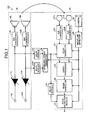
- FIG. 7 is an exemplary block diagram of a structure of an echo reduction module in the embodiment.
- FIG. 8 is an exemplary schematic diagram for explaining operation of the echo reduction module in the embodiment.
- FIG. 9 is an exemplary schematic diagram illustrating a level of an echo included in the amplitude spectrum in the embodiment.
- FIG. 10 is an exemplary block diagram of a structure of a signal processor according to a modification example 1 of the embodiment.
- FIG. 11 is an exemplary block diagram of a structure of a signal processor according to a modification example 2 of the embodiment.
- FIG. 12 is an exemplary block diagram of a structure of a signal processor according to a modification example 3 of the embodiment.
- FIG. 13 is an exemplary block diagram of a structure of an echo reduction module according to the modification examples 2 and 3.
- a signal processor comprises a plurality of loudspeakers, a plurality of microphones, a detector, and a signal processor.
- the plurality of loudspeakers is configured to reproduce sound of a plurality of channels.
- the plurality of microphones is configured to pick up sound of a plurality of channels.
- the detector is configured to detect a user who is present in a direction of a space from which the microphones pickup the sound, and output directional characteristic information indicating a relative direction of the user to the loudspeakers.
- the signal processor is configured to switch contents of processing to reduce a disturbance signal included in a picked-up sound signal of the sound picked up by the microphones from the picked-up sound signal based on the relative direction indicated by the directional characteristic information.
- FIG. 1 is a block diagram of a structure of a signal processor according to an embodiment. As illustrated in FIG. 1 , a signal processor 100 comprises an acoustic output module 10 and a signal processor 20 .
- the acoustic output module 10 comprises volume modules 11 L and 11 R, digital-to-analog (D/A) converters 12 L and 12 R, and loudspeakers 13 L and 13 R.
- D/A digital-to-analog
- the volume module 11 L regulates a volume of an acoustic signal for a left channel (hereinafter referred to as an Lch) received from an input terminal 14 L based on an operation amount of a volume adjustment switch (not illustrated).
- the volume module 11 R regulates a volume of an acoustic signal for a right channel (hereinafter referred to as an Rch) received from an input terminal 14 R based on an operation amount of a volume adjustment switch (not illustrated).
- the D/A converter 12 L converts a digital acoustic signal whose volume has been regulated by the volume module 11 L into an analog signal, and outputs the analog signal to the loudspeaker 13 L.
- the D/A converter 12 R converts a digital acoustic signal whose volume has been regulated by the volume module 11 R into an analog signal, and outputs the analog signal to the loudspeaker 13 R.
- the loudspeakers 13 L and 13 R form a stereo loudspeaker system, and output sound (reproduced sound) in a space in which the signal processor 100 is disposed.
- the loudspeaker 13 L converts the analog signal received from the D/A converter 12 L into a physical vibration, and outputs a sound (reproduced sound).
- the loudspeaker 13 R converts the analog signal received from the D/A converter 12 R into a physical vibration, and outputs a sound (reproduced sound).
- the signal processor 20 comprises microphones 21 L and 21 R, analog-to-digital (A/D) converters 22 L and 22 R, delay modules 23 L and 23 R, a monaural signal generator 24 , a camera 25 , a sight line detector 26 , an echo canceller 27 , an array processor 28 , a noise canceller 29 , a delay module 30 , and an echo reduction module 31 .
- A/D analog-to-digital
- the microphones 21 L and 21 R form a stereo microphone system, and pick up sound traveling in the space in which the signal processor 100 is disposed.
- the microphone 21 L outputs a picked-up sound to the A/D converter 22 L as an analog picked-up sound signal (hereinafter referred to as an Lch picked-up sound signal).
- the microphone 21 R outputs a picked-up sound to the A/D converter 22 R as an analog picked-up sound signal (hereinafter referred to as an Rch picked-up sound signal).
- the A/D converter 22 L converts the Lch picked-up sound signal picked up by the microphone 21 L into a digital signal, and outputs the digital signal to the echo canceller 27 .
- the A/D converter 22 R converts the Rch picked-up sound signal picked up by the microphone 21 R into a digital signal, and outputs the digital signal to the echo canceller 27 .
- the delay modules 23 L and 23 R are delay circuits, for example.
- the delay module 23 L delays, for a predetermined period of time, the digital acoustic signal whose volume has been regulated by the volume module 11 L, and outputs the delayed signal to the monaural signal generator 24 .
- the delay module 23 R delays, for a predetermined period of time, the digital acoustic signal whose volume has been regulated by the volume module 11 R, and outputs the delayed signal to the monaural signal generator 24 .
- the monaural signal generator 24 calculates a linear sum of the acoustic signal received from the delay module 23 L and the acoustic signal received from the delay module 23 R based on formula (I), and outputs a signal that is the result of the calculation to the echo canceller 27 and the delay module 30 .
- L indicates the acoustic signal received from the delay module 23 L
- R indicates the acoustic signal received from the delay module 23 R
- ⁇ indicates the coefficient that is specified based on directional characteristic information described later (0 ⁇ 1).
- the monaural signal generator 24 adjusts a value of the coefficient ⁇ of formula (I) based on the directional characteristic information received from the sight line detector 26 to change a weight for each of acoustic signals “L” and “R”. More specifically, when the directional characteristic information indicates an “area L” described later, the monaural signal generator 24 increases the value of the coefficient ⁇ to increase the weight of the acoustic signal “L”. When the directional characteristic information indicates an “area R” described later, the monaural signal generator 24 decreases the value of the coefficient ⁇ to increase the weight of the acoustic signal “R”. When the directional characteristic information indicates an “area C” described later, the monaural signal generator 24 halves the value of the coefficient ⁇ to equalize the weights of the acoustic signals “L” and “R”.
- the camera 25 is an imaging device.
- the camera 25 is disposed such that it faces a space from which the microphones 21 L and 21 R pick up sound (faces a space direction), i.e., the space to which the loudspeakers 13 L and 13 R output sound (faces an output direction of the loudspeakers).
- the camera 25 captures images and outputs imaged data to the sight line detector 26 .
- the sight line detector 26 analyzes the imaged data received from the camera 25 .
- the sight line detector 26 When detecting an utterer who is present in the output direction of the loudspeakers 13 L and 13 R, the sight line detector 26 produces directional characteristic information that indicates the location of the utterer in the image with a relative direction (relative position) to the loudspeakers 13 L and 13 R, and outputs the information to the monaural signal generator 24 , the echo canceller 27 , the array processor 28 , the noise canceller 29 , and the echo reduction module 31 .
- the sight line detector 26 detects faces and lines of sight of persons in an image of imaged data, and detects a person whose face and line of sight face the frontal direction of the person, i.e., face the camera 25 , as an utterer.
- the known techniques may be used as analysis methods to detect the faces and lines of sight from the imaged data.
- the directional characteristic information that indicates the relative direction of the utterer (user) to a plurality of loudspeakers depends on positional information of the arrangement of the loudspeakers and a plurality of microphones. Furthermore, the directional characteristic information depends on the picking-up sound directivity of a microphone array set by the arrangement of the microphones, and information indicating which microphone picks up an echo from which loudspeaker depending on the picking-up sound directivity of each microphone.
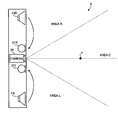
- FIG. 2 is a schematic diagram for explaining operation of the sight line detector 26 .
- FIG. 2 illustrates an arrangement relationship among the loudspeakers 13 L and 13 R, the microphones 21 L and 21 R, and the camera 25 in the top view.
- the loudspeakers 13 L and 13 R are disposed apart from each other with a predetermined distance.
- the loudspeaker 13 L is disposed on the left side while the loudspeaker 13 R is disposed on the right side.
- the microphones 21 L and 21 R are disposed between the loudspeakers 13 L and 13 R.
- the microphone 21 L is disposed on the left side while the microphone 21 R is disposed on the right side.
- the camera 25 is disposed between the microphones 21 L and 21 R, and captures images in a space A to which sound are output.
- the loudspeakers 13 L and 13 R, and the microphones 21 L and 21 R are symmetrically disposed with an imaging direction of the camera 25 as the symmetrical axis.
- the space A is defined as a plurality of divided regions (areas).
- the sight line detector 26 outputs the directional characteristic information indicating the area in which an utterer is present. For example, when detecting an utterer SP in the area L near the loudspeaker 13 L in the space Abased on imaged data taken by the camera 25 , the sight line detector 26 outputs the directional characteristic information indicating the area L.
- the directional characteristic information indicating the relative direction of the utterer (user) to the loudspeakers is given, for example, with an angle made between the utterer and the loudspeaker R, an angle made between the utterer and the loudspeaker L, and the area in which the utterer is present.
- the space A comprises three areas and each area is defined as follows.
- the “area C” is defined as a space extending from an imaging position of toward an imaging direction of the camera 25 within an angle of ⁇ 22.5 degrees from the imaging position as a reference position.
- the “area L” is defined, in the space A, as a space that is located near the loudspeaker 13 L and excludes the area C.
- the “area R” is defined, in the space A, as a space that is located near the loudspeaker 13 R and excludes the area C.
- the number of divided areas and the sizes of the areas are not limited to those in FIG. 2 .
- the arrangement relationship among the loudspeakers 13 L and 13 R, the microphones 21 L and 21 R, and the camera 25 is not limited to that in FIG. 2 .
- the echo canceller 27 removes echo components included in the picked-up sound signals received from the A/D converters 22 L and 22 R based on the directional characteristic information received from the sight line detector 26 .
- the structure of the echo canceller 27 is described below with reference to FIG. 3 .
- FIG. 3 is a block diagram of a structure of the echo canceller 27 .
- the echo canceller 27 allows a switching module 271 to perform switching based on the directional characteristic information received from the sight line detector 26 . Specifically, when the directional characteristic information indicates the “area L” or the “area R”, the echo canceller 27 allows the switching module 271 to perform switching to operate a first processor 272 while when the directional characteristic information indicates the “area C”, the echo canceller 27 allows the switching module 271 to perform switching to operate a second processor 273 .
- the first processor 272 comprises subtractors 2721 L and 2721 R, adaptive filter learning modules 2722 L and 2722 R, and quasi-echo generators 2723 L and 2723 R.
- the subtractor 2721 L subtracts a quasi-echo signal produced by the quasi-echo generator 2723 L from the Lch picked-up sound signal received from the A/D converter 22 L, and outputs a residual echo signal that is the result of the subtraction to the adaptive filter learning module 2722 L and the array processor 28 .
- the adaptive filter learning module 2722 L estimates and learns a transfer function between the loudspeaker 13 L and the microphone 21 L based on the signal received from the monaural signal generator 24 through the switching module 271 as a reference signal and the residual echo signal output from the subtractor 2721 L.
- the quasi-echo generator 2723 L multiplies the signal received from the monaural signal generator 24 through the switching module 271 by the transfer function having been estimated and learned by the adaptive filter learning module 2722 L to produce the quasi-echo signal, and outputs the quasi-echo signal to the subtractor 2721 L.
- the subtractor 2721 R subtracts the quasi-echo signal produced by the quasi-echo generator 2723 R from the Rch picked-up sound signal received from the A/D converter 22 R, and outputs the residual echo signal that is the result of the subtraction to the adaptive filter learning module 2722 R and the array processor 28 .
- the adaptive filter learning module 2722 R estimates and learns the transfer function between the loudspeaker 13 R and the microphone 21 R based on the signal received from the monaural signal generator 24 through the switching module 271 as the reference signal and the residual echo signal output from the subtractor 2721 R.
- the quasi-echo generator 2723 R multiplies the signal received from the monaural signal generator 24 through the switching module 271 by the transfer function estimated and learned by the adaptive filter learning module 2722 R (convolute an input signal with a filter coefficient) to produce the quasi-echo signal, and outputs the quasi-echo signal to the subtractor 2721 R.
- the second processor 273 comprises a monaural signal generator 2731 , a subtractor 2732 , an adaptive filter learning module 2733 , a quasi-echo generator 2734 , and subtractors 2735 L and 2735 R.
- the monaural signal generator 2731 calculates a mean value of the Lch picked-up sound signal received from the A/D converter 22 L and the Rch picked-up sound signal received from the A/D converter 22 R, and outputs the calculation result to the subtractor 2732 .
- the method to calculate the mean value is not limited to above. For example, the linear sum of the two signal values may be divided by two to find the mean value.
- the subtractor 2732 subtracts the quasi-echo signal produced by the quasi-echo generator 2734 from the signal received from the monaural signal generator 2731 , and outputs the residual echo signal that is the result of the subtraction to the adaptive filter learning module 2733 .
- the adaptive filter learning module 2733 estimates and learns the transfer function between the loudspeaker group (loudspeakers 13 L and 13 R) and the microphone group (microphones 21 L and 21 R) based on the signal received from the monaural signal generator 24 through the switching module 271 and the residual echo signal output from the subtractor 2732 .
- the quasi-echo generator 2734 produces the quasi-echo signal by using the signal received from the monaural signal generator 24 through the switching module 271 and the transfer function estimated and learned by the adaptive filter learning module 2733 , and outputs the quasi-echo signal to the subtractor 2732 , and the subtractors 2735 L and 2735 R.
- the subtractor 2735 L subtracts the quasi-echo signal produced by the quasi-echo generator 2734 from the signal received from the A/D converter 22 L, and outputs the residual echo signal that is the result of the subtraction to the array processor 28 .
- the subtractor 2735 R subtracts the quasi-echo signal produced by the quasi-echo generator 2734 from the signal received from the A/D converter 22 R, and outputs the residual echo signal that is the result of the subtraction to the array processor 28 .
- the echo canceller 27 calculates the mean value of the Lch picked-up sound signal and the Rch picked-up sound signal, and removes an echo component based on the common component in both picked-up sound signals. This processing can reduce the load necessary for removing the echo component compared to the case when the directional characteristic information indicates the “area L” or the “area R”.
- the array processor 28 selectively extracts a signal traveling from a sound source (an utterer) direction indicated by the directional characteristic information from signals received from the echo canceller 27 by using the directional characteristic information received from the sight line detector 26 , and outputs the extracted signal to the noise canceller 29 .
- the array processor 28 performs delay processing and other processing on the picked-up sound signals that are picked up by the microphones 21 L and 21 R and received through the echo canceller 27 to produce a plurality of picked-up sound beam signals having directivity axes in different directions.
- the array processor 28 selects a picked-up sound beam signal corresponding to a direction indicated by the directional characteristic information received from the sight line detector 26 out of the picked-up sound beam signals, removes an echo from the selected picked-up sound beam signal, and transmits the resulting signal to the noise canceller 29 .
- the array processor 28 may selectively extract a signal traveling from a direction in which an utterer is present (any of the areas L, R, and C) by tracking a sound source direction, or may selectively extract a signal from an utterer who is present in the specific sound source direction (e.g., the area C).
- Known techniques are used as methods for extracting a signal from picked-up sound beam signals and removing an echo from the selected picked-up sound beam signal.
- the noise canceller 29 functions to suppress a noise component included in the signal after being processed by the array processor 28 .
- the structure of the noise canceller 29 is described below with reference to FIG. 4 .
- FIG. 4 is a block diagram of a structure of the noise canceller 29 .
- the noise canceller 29 comprises a frequency domain converter 291 , a noise interval estimator 292 , a noise characteristic estimator 293 , a suppression gain calculator 294 , a noise suppressor 295 , and a time domain converter 296 .
- the frequency domain converter 291 converts the signal in a time domain received from the array processor 28 into the signal in a frequency domain, outputs an amplitude spectrum of the converted signal to the noise suppressor 295 , and outputs a phase spectrum of the converted signal to the time domain converter 296 .
- the noise interval estimator 292 estimates an interval having smallest power (e.g., a tiny period of time around time at which power is smallest) in the signal received from the array processor 28 as a noise interval, and outputs the signal (waveform) corresponding to the noise interval to the noise characteristic estimator 293 .
- the noise characteristic estimator 293 sequentially estimates a characteristic value (noise characteristic) of a surrounding ambient noise from the signal of the noise interval received from the noise interval estimator 292 by using a maximum-likelihood approach, for example, and outputs the estimated noise characteristic to the suppression gain calculator 294 .
- the noise characteristic estimator 293 receives the directional characteristic information output from the sight line detector 26 .
- the noise characteristic estimator 293 shortens a time interval to sequentially estimate and update the characteristic value, or increases an updating amount.
- the noise characteristic estimator 293 lengthens the time interval to sequentially estimate and update the characteristic value to the original time interval or decreases the updating amount to the original updating amount. In this way, a follow-up speed of the noise characteristic is speeded up when the area indicated by the directional characteristic information is changed. Accordingly, the noise characteristic of the changed area can be quickly simulated.
- a plurality of noise characteristics corresponding to the areas may be stored.
- a noise characteristic corresponding to the area indicated by the received directional characteristic information is read and updated.
- the noise characteristic is output to the suppression gain calculator 294 .
- the suppression gain calculator 294 calculates a suppression gain for sound suppression processing according to the noise characteristic received from the noise characteristic estimator 293 .
- the noise suppressor 295 performs suppression on the amplitude spectrum received from the frequency domain converter 291 by using the suppression gain calculated by the suppression gain calculator 294 to suppress a noise included in the amplitude spectrum, and outputs the amplitude spectrum after the suppression to the time domain converter 296 .
- the noise suppressor 295 turns on or off the suppression depending on the directional characteristic information received from the sight line detector 26 , and a direction of a noise source identified by a level of the noise included in the amplitude spectrum received from the array processor 28 . Specifically, when the array processor 28 is set to track the sound source, the noise suppressor 295 turns on the suppressing if the sound source direction indicated by the directional characteristic information coincides with the direction of the noise source while the noise suppressor 295 turns off the suppressing if both directions do not coincide with each other.
- the noise suppressor 295 turns on the suppressing if the sound source direction indicated by the directional characteristic information coincides with the direction of the specific sound source while the noise suppressor 295 turns off the suppressing if both directions do not coincide with each other.
- FIG. 5 is a schematic diagram for explaining operation of the noise canceller 29 (the noise suppressor 295 ).
- FIG. 5 illustrates an arrangement relationship among the loudspeakers 13 L and 13 R, the microphones 21 L and 21 R, and the camera 25 in the top view, in the same manner as FIG. 3 .
- an utterer is present in the area C, and a noise source N moves from the area R to the area C, and then to the area L as time elapses.
- the noise suppressor 295 turns on the suppression if the direction of the sound source indicated by the directional characteristic information, i.e., the area C in which the utterer SP is present, coincides with an appearance direction of the noise source N identified by the level of the noise included in the amplitude spectrum received from the array processor 28 while the noise suppressor 295 turns off the suppressing if both directions do not coincide with each other.
- the suppression is turned off in a period of time T 0 to T 1 during which the noise source N is present in the area R because the area C in which the utterer SP is present and the direction of the noise source N (the area R) do not coincide with each other.
- the suppression is turned on in a period of time T 1 to T 2 during which the noise source N is present in the area C because the area C in which the utterer SP is present coincides with the direction of the noise source N (the area C).
- the suppression is turned off in a period of time T 2 to T 3 during which the noise source N is present in the area L because the area C in which the utterer SP is present and the direction of the noise source N (the area L) do not coincide with each other.
- the noise suppressor 295 turns on the suppressing if the sound source direction indicated by the directional characteristic information coincides with the specific sound source direction while the noise suppressor 295 turns off the suppressing if both directions do not coincide with each other.
- the level of the noise included in the amplitude spectrum received from the array processor 28 is illustrated in FIG. 6 .
- FIG. 6 is a schematic diagram exemplarily illustrating the level of the noise included in the amplitude spectrum when the array processor 28 extracts a signal traveling from a specific sound source direction (the area C).
- the noise level when the sound source direction is the area C is markedly higher than the noise levels of the other areas.
- the noise suppressor 295 turns on the suppression while when the directional characteristic information indicates the other areas the noise suppressor 295 turns off the suppression.
- the noise suppressor 295 controls the turning on or off of the suppression in the embodiment. However, the control is not limited to be performed by the noise suppressor 295 .
- the suppression gain calculator 294 may set the suppression gain to zero when the suppression is turned off based on the same turning on or off condition as the noise suppressor 295 .
- the time domain converter 296 converts the signal in the frequency domain into the signal in the time domain based on the amplitude spectrum received from the noise suppressor 295 and the phase spectrum received from the frequency domain converter 291 , and outputs a signal that is the result of the conversion to the echo reduction module 31 .
- the delay module 30 is a delay circuit, for example, in the same manner as the delay modules 23 L and 23 R, delays the signal received from the monaural signal generator 24 for a predetermined period of time, and outputs the delayed signal to the echo reduction module 31 .
- the delay module 30 the signal that is output from the monaural signal generator 24 and input to the echo reduction module 31 through the echo canceller 27 , the array processor 28 , and the noise canceller 29 , and the signal that is output from the monaural signal generator 24 and input to the echo reduction module 31 through the delay module 30 synchronize with each other.
- the echo reduction module 31 functions to remove an echo component included in the signal after being processed by the noise canceller 29 .
- the structure of the echo reduction module 31 is described below with reference to FIG. 7 .
- FIG. 7 is a block diagram of a structure of the echo reduction module 31 .
- the echo reduction module 31 comprises a first frequency domain converter 311 , a second frequency domain converter 312 , an echo interval estimator 313 , an acoustic characteristic estimator 314 , a suppression gain calculator 315 , an echo suppressor 316 , and a time domain converter 317 .
- the first frequency domain converter 311 converts the signal in the time domain received from the delay module 30 into the signal in the frequency domain, and outputs the amplitude spectrum of the converted signal to the echo interval estimator 313 , the acoustic characteristic estimator 314 , and the suppression gain calculator 315 .
- the second frequency domain converter 312 converts the signal in the time domain received from the noise canceller 29 into the signal in the frequency domain, outputs the amplitude spectrum of the converted signal to the echo interval estimator 313 , the acoustic characteristic estimator 314 , and the echo suppressor 316 , and outputs the phase spectrum of the converted signal to the time domain converter 317 .
- the echo interval estimator 313 receives the signal from the noise canceller 29 , the signal from the delay module 30 , the amplitude spectrum from the first frequency domain converter 311 , and the amplitude spectrum from the second frequency domain converter 312 .
- the echo interval estimator 313 notifies the acoustic characteristic estimator 314 of an echo interval in which it is estimated that an echo occurs based on a difference value of the signal from the noise canceller 29 and the signal from the delay module 30 , and a difference value between the amplitude spectra, for example.
- the acoustic characteristic estimator 314 receives the amplitude spectrum from the first frequency domain converter 311 , the amplitude spectrum from the second frequency domain converter 312 , and the echo interval notified by the echo interval estimator 313 .
- the acoustic characteristic estimator 314 estimates an acoustic characteristic of the echo component from a difference of two amplitude spectra in the echo interval notified by the echo interval estimator 313 , and outputs the estimated acoustic characteristic to the suppression gain calculator 315 .
- the acoustic characteristic estimator 314 receives the directional characteristic information output from the sight line detector 26 .
- the acoustic characteristic estimator 314 shortens the time interval to sequentially estimate and update the acoustic characteristic or increases the updating amount.
- the acoustic characteristic estimator 314 lengthens the time interval to sequentially estimate and update the acoustic characteristic to the original time interval or decreases the updating amount to the original updating amount. In this way, a follow-up speed of the acoustic characteristic is speeded up when the area indicated by the directional characteristic information is changed.
- the acoustic characteristic of the changed area can be quickly simulated. As a result, lowering of an echo suppression amount can be prevented.
- the following manner may be employed.
- a plurality of acoustic characteristics corresponding to the areas may be stored.
- An acoustic characteristic corresponding to the area indicated by the received directional characteristic information is read and updated.
- the read acoustic characteristic is output to the suppression gain calculator 315 .
- the suppression gain calculator 315 calculates a suppression gain for echo suppression according to the acoustic characteristic received from the acoustic characteristic estimator 314 , and outputs the suppression gain to the echo suppressor 316 .
- the echo suppressor 316 performs suppression on the amplitude spectrum received from the second frequency domain converter 312 by using the suppression gain calculated by the suppression gain calculator 315 to suppress an echo component included in the amplitude spectrum, and outputs the amplitude spectrum after the suppression to the time domain converter 296 .
- the echo suppressor 316 turns on or off depending on the directional characteristic information received from the sight line detector 26 , and a signal extraction setting in the noise canceller 29 . Specifically, when the array processor 28 is set to extract a signal traveling from a specific sound source direction (e.g., the area C), the echo suppressor 316 turns off the suppressing if the sound source direction indicated by the directional characteristic information coincides with the specific sound source direction while the echo suppressor 316 turns on the suppressing if both directions do not coincide with each other. When the array processor 28 is set to track the sound source, the echo suppressor 316 turns on the suppressing for all of the sound source directions.
- a specific sound source direction e.g., the area C
- FIG. 8 is a schematic diagram for explaining operation of the echo reduction module 31 (the echo suppressor 316 ).
- FIG. 8 illustrates an arrangement relationship among the loudspeakers 13 L and 13 R, the microphones 21 L and 21 R, and the camera 25 in the top view, in the same manner as FIG. 3 .
- the utterer SP moves from the area R to the area C, and then to the area L as time elapses.
- the level of an echo included in the amplitude spectrum received from the second frequency domain converter 312 is illustrated in FIG. 9 when the array processor 28 is set to extract a signal traveling from the area C.
- FIG. 9 is a schematic diagram exemplarily illustrating the level of the echo included in the amplitude spectrum when the array processor 28 extracts a signal traveling from a specific sound source direction (the area C).
- the echo level when the sound source direction is the area C is reduced compared to the echo levels of the other areas as a result of processing by the array processor 28 .
- the echo suppressor 316 turns off the suppression while when the directional characteristic information indicates the other areas the noise suppressor 295 turns on the suppression.
- the echo suppressor 316 controls the turning on or off of the suppression in the embodiment. However, the control is not limited to be performed by the echo suppressor 316 .
- the suppression gain calculator 315 may set the suppression gain to zero when the suppression is turned off based on the same turning on or off condition as the echo suppressor 316 .
- the signal after the suppression performed by the echo reduction module 31 is output to an external apparatus (not illustrated).
- the signal processor 20 identifies an utterer presence direction relative to the signal processor 100 as the directional characteristic information, removes and suppresses a disturbance signal such as an echo and a noise based on the direction indicated by the directional characteristic information, enabling voices uttered by the utterer to be effectively produced as clear voices.
- a direction in which an utterer is present is identified by the functions of the camera 25 and the sight line detector 26 .
- the direction is not limited to be detected by the functions of the camera 25 and the sight line detector 26 .
- the direction in which an utterer is present may be identified based on picked-up sound signals picked up by the microphones 21 L and 21 R. This structure is described below as a modification example 1 of the embodiment.
- FIG. 10 is a block diagram of a structure of a signal processor 20 A according to the modification example 1 of the embodiment.
- the same elements as the embodiment are labeled with the same reference numerals, and description thereof is omitted.
- the signal processor 20 A comprises the microphones 21 L and 21 R, the A/D converters 22 L and 22 R, the delay modules 23 L and 23 R, the monaural signal generator 24 , the echo canceller 27 , the array processor 28 , the noise canceller 29 , the delay module 30 , the echo reduction module 31 , and an arrival direction estimator 32 .
- the arrival direction estimator 32 receives the Lch picked-up sound signal output from the A/D converter 22 L and the Rch picked-up sound signal output from the A/D converter 22 R.
- the arrival direction estimator 32 performs delay processing, for example, on each of picked-up sound signals picked up by the microphones 21 L and 21 R to produce a plurality of picked-up sound beam signals having directivity axes in different directions.
- the arrival direction estimator 32 selects a picked-up sound beam signal having a highest signal level out of the picked-up sound beam signals, identifies a direction corresponding to the picked-up sound beam signal as the utterer presence direction, and outputs the directional characteristic information indicating the utterer presence direction to the monaural signal generator 24 , the echo canceller 27 , the array processor 28 , the noise canceller 29 , and the echo reduction module 31 .
- the arrival direction estimator 32 which is provided instead of the camera 25 and the sight line detector 26 , can identify the utterer presence direction based on the sound picked up by the microphones 21 L and 21 R.
- the modification example 1 thus, can exhibit the same effect as the embodiment, and can also simplify the structure of the signal processor.
- the signal processing to remove and suppress disturbance signals included in the sound picked up by the microphones 21 L and 21 R is performed by the echo canceller 27 , the array processor 28 , the noise canceller 29 , and the echo reduction module 31 in this order.
- the structure to perform the signal processing is not limited to the structure of the signal processor 20 .
- the structure of the signal processor 20 may be modified by changing the performing order of the signal processing, or integrating the functions to omit specific signal processing, for example. Examples of the structural modification of the signal processor 20 are described below as modification examples 2 and 3.
- FIG. 11 is a block diagram of a structure of a signal processor 20 B according to the modification example 2 of the embodiment.
- the same elements as the embodiment are labeled with the same reference numerals, and description thereof is omitted.
- the signal processor 20 B comprises the microphones 21 L and 21 R, the A/D converters 22 L and 22 R, the delay modules 23 L and 23 R, the monaural signal generator 24 , the camera 25 , the sight line detector 26 , the echo canceller 27 , an echo reduction module 31 B, the array processor 28 , and the noise canceller 29 .
- the structure of the signal processor 20 B differs from that of the signal processor 20 illustrated in FIG. 1 in that the delay module 30 is excluded, and the signal processing is performed by the echo reduction module 31 B, the array processor 28 , and the noise canceller 29 in this order after processing of the echo canceller 27 .
- FIG. 12 is a block diagram of a structure of a signal processor 20 C according to the modification example 3 of the embodiment.
- the same elements as the embodiment are labeled with the same reference numerals, and description thereof is omitted.
- the signal processor 20 C comprises the microphones 21 L and 21 R, the A/D converters 22 L and 22 R, the delay modules 23 L and 23 R, the monaural signal generator 24 , the camera 25 , the sight line detector 26 , an echo reduction module 31 C, the array processor 28 , and the noise canceller 29 .
- the structure of the signal processor 20 C differs from that of the signal processor 20 illustrated in FIG. 1 in that the delay module 30 and the echo canceller 27 are excluded, and the signal processing is performed by the echo reduction module 31 C, the array processor 28 , and the noise canceller 29 in this order.
- the echo reduction modules 31 B and 31 C each receives the Lch and the Rch picked-up sound signals, i.e., two signal lines. Therefore, the echo reduction modules 31 B and 31 C adopt the structure illustrated in FIG. 13 instead of the structure illustrated in FIG. 7 .
- FIG. 13 is a block diagram of a structure of the echo reduction modules 31 B and 31 C according to the modification examples 2 and 3.
- each of the echo reduction modules 31 B and 31 C comprises a first frequency domain converter 411 , a first monaural signal generator 412 , a second frequency domain converter 413 , a third frequency domain converter 414 , a second monaural signal generator 415 , an echo interval estimator 416 , an acoustic characteristic estimator 417 , a suppression gain calculator 418 , a first echo suppressor 419 , a first time domain converter 420 , a second echo suppressor 421 , and a second time domain converter 422 .
- the first frequency domain converter 411 converts the signal in the time domain received from the monaural signal generator 24 into the signal in the frequency domain, and outputs the amplitude spectrum of the converted signal to the echo interval estimator 416 , the acoustic characteristic estimator 417 , and the suppression gain calculator 418 .
- the first monaural signal generator 412 calculates a mean value of the Lch picked-up sound signal received from the A/D converter 22 L and the Rch picked-up sound signal received from the A/D converter 22 R, and outputs the calculation result to the echo interval estimator 416 .
- the second frequency domain converter 413 converts the Lch picked-up sound signal in the time domain received from the A/D converter 22 L into the signal in the frequency domain, outputs the amplitude spectrum of the converted signal to the second monaural signal generator 415 and the first echo suppressor 419 , and outputs the phase spectrum of the converted signal to the first time domain converter 420 .
- the third frequency domain converter 414 converts the Rch picked-up sound signal in the time domain received from the A/D converter 22 R into the signal in the frequency domain, outputs the amplitude spectrum of the converted signal to the second monaural signal generator 415 and the second echo suppressor 421 , and outputs the phase spectrum of the converted signal to the second time domain converter 422 .
- the second monaural signal generator 415 calculates a mean value of the amplitude spectra each received from the second frequency domain converter 413 and the third frequency domain converter 414 , and outputs the calculation result to the echo interval estimator 416 and the acoustic characteristic estimator 417 .
- the echo interval estimator 416 receives the signal from the monaural signal generator 24 , the amplitude spectrum from the first frequency domain converter 411 , the signal from the first monaural signal generator 412 , and the amplitude spectrum from the second monaural signal generator 415 .
- the echo interval estimator 416 notifies the acoustic characteristic estimator 417 of an echo interval in which it is estimated that an echo occurs based on a difference value of the signal from the first monaural signal generator 412 and the signal from the monaural signal generator 24 , and a difference value between the amplitude spectra, for example, by the same function as the echo interval estimator 313 .
- the acoustic characteristic estimator 417 receives the amplitude spectrum from the first frequency domain converter 411 , the amplitude spectrum from the second monaural signal generator 415 , and the echo interval notified by the echo interval estimator 416 .
- the acoustic characteristic estimator 417 estimates an acoustic characteristic of the echo component from a difference of two amplitude spectra in the echo interval notified by the echo interval estimator 416 , and outputs the estimated acoustic characteristic to the suppression gain calculator 418 in the same function as the acoustic characteristic estimator 314 .
- the acoustic characteristic estimator 417 receives the directional characteristic information output from the sight line detector 26 , and changes the time interval to estimate the acoustic characteristic based on the direction indicated by the directional characteristic information. Specifically, the acoustic characteristic estimator 417 shortens the time interval when the directional characteristic information indicates the “area C” compared to the time interval when the directional characteristic information indicates the “area L” or the “area R”. As a result, the acoustic characteristic estimator 417 increases an estimation speed of the acoustic characteristic when an utterer is present in the “area C” compared to the case when the utterer is present in the other areas. In the embodiment, the acoustic characteristic is sequentially estimated.
- the acoustic characteristic is not limited to be sequentially estimated.
- acoustic characteristics corresponding to the respective areas may be preliminarily stored, and an acoustic characteristic of the direction corresponding to the received directional characteristic information may be output to the suppression gain calculator 418 .
- the suppression gain calculator 418 calculates a suppression gain for echo suppression according to the acoustic characteristic received from the acoustic characteristic estimator 417 , and outputs the suppression gain to the first echo suppressor 419 and the second echo suppressor 421 .
- the first echo suppressor 419 performs suppression on the amplitude spectrum received from the second frequency domain converter 413 by using the suppression gain calculated by the suppression gain calculator 418 to suppress an echo component included in the amplitude spectrum, and outputs the amplitude spectrum after the suppression to the first time domain converter 420 .
- the first echo suppressor 419 may perform suppression based on the directional characteristic information in the same manner as the echo suppressor 316 .
- the first time domain converter 420 converts the signal in the frequency domain into the signal in the time domain based on the amplitude spectrum received from the first echo suppressor 419 and the phase spectrum received from the second frequency domain converter 413 , and outputs a signal that is the result of the conversion to the array processor 28 as the Lch picked-up sound signal.
- the second echo suppressor 421 performs suppression on the amplitude spectrum received from the third frequency domain converter 414 by using the suppression gain calculated by the suppression gain calculator 418 to suppress an echo component included in the amplitude spectrum, and outputs the amplitude spectrum after the suppression to the second time domain converter 422 .
- the second echo suppressor 421 may perform suppression based on the directional characteristic information in the same manner as the echo suppressor 316 .
- the second time domain converter 422 converts the signal in the frequency domain into t the signal in the time domain based on the amplitude spectrum received from the second echo suppressor 421 and the phase spectrum received from the third frequency domain converter 414 , and outputs a signal that is the result of the conversion to the array processor 28 as the Rch picked-up sound signal.
- the use of the echo reduction modules 31 B and 31 C thus structured can realize the signal processors 20 B and 20 C.
- a mean value of the Lch picked-up sound signal and the Rch picked-up sound signal is calculated, and an echo component is suppressed based on the common component in both picked-up sound signals. Therefore, the load necessary for suppressing the echo component can be reduced.
- disturbance signals may be removed and suppressed by three processors, i.e., the echo canceller 27 , the echo reduction module 31 B (or 31 C), and the array processor 28 in this order.
- disturbance signals may be removed and suppressed by two processor, i.e., the echo reduction module 31 B (or 31 C), and the array processor 28 in this order.
- two loudspeakers are used.
- the number of loudspeakers is not limited to two. More than two loudspeakers may be used.
- two microphones are used. However, the number of microphones is not limited to two. More than two microphones may be used.
- the signal processor of the embodiment can be applied to any applications.
- the signal processor is applicable as a device for pre-processing such as voice recognition in various apparatuses such as cell-phones, notebook personal computers, and tablet terminals.
- modules of the systems described herein can be implemented as software applications, hardware and/or software modules, or components on one or more computers, such as servers. While the various modules are illustrated separately, they may share some or all of the same underlying logic or code.
Landscapes
- Health & Medical Sciences (AREA)
- Otolaryngology (AREA)
- Engineering & Computer Science (AREA)
- Signal Processing (AREA)
- Physics & Mathematics (AREA)
- Acoustics & Sound (AREA)
- Multimedia (AREA)
- Circuit For Audible Band Transducer (AREA)
- Obtaining Desirable Characteristics In Audible-Bandwidth Transducers (AREA)
- Cable Transmission Systems, Equalization Of Radio And Reduction Of Echo (AREA)
Abstract
Description
- This application is based upon and claims the benefit of priority from Japanese Patent Application No. 2011-080786, filed Mar. 31, 2011, the entire contents of which are incorporated herein by reference.
- An embodiment described herein relates generally to a signal processor and a signal processing method.
- Conventionally, disturbance signals such as noise components and echo components included in an acoustic signal have been reduced by using a digital signal processor (DSP), for example. In the DSP, a noise canceller and an echo canceller change characteristics of the acoustic signal to reduce such disturbance signals. A technique using a plurality of microphones (a microphone array) has been proposed for reducing disturbance signals such as noise components and echo components included in a picked-up sound signal obtained by the microphone array and outputting the resulting signal as an output signal. For picking up sound by using a plurality of microphones, a technique (an utterer tracking microphone array) has also been proposed in which directivity of the microphones is directed toward a user who utters, and disturbance signals such as noise components are reduced by adaptively changing the directivity.
- When the utterer tracking microphone array for picking up sound and a plurality of loudspeakers for outputting acoustic signals are used together, the directivity for picking up sound changes as a user moves in a space to which the acoustic signals are output. As a result, loudspeakers causing an echo are shifted according to the location of the utterer. The conventional technique, however, cannot effectively reduce the disturbance signals generated in relation to the location of the user because a relative direction (relative position) between the user and the loudspeakers is not taken into consideration to reduce the disturbance signals.
- A general architecture that implements the various features of the invention will now be described with reference to the drawings. The drawings and the associated descriptions are provided to illustrate embodiments of the invention and not to limit the scope of the invention.
-
FIG. 1 is an exemplary block diagram of a structure of a signal processor according to an embodiment; -
FIG. 2 is an exemplary schematic diagram for explaining operation of a sight line detector in the embodiment; -
FIG. 3 is an exemplary block diagram of a structure of an echo canceller in the embodiment; -
FIG. 4 is an exemplary block diagram of a structure of a noise canceller in the embodiment; -
FIG. 5 is an exemplary schematic diagram for explaining operation of the noise canceller in the embodiment; -
FIG. 6 is an exemplary schematic diagram illustrating a level of a noise included in an amplitude spectrum in the embodiment; -
FIG. 7 is an exemplary block diagram of a structure of an echo reduction module in the embodiment; -
FIG. 8 is an exemplary schematic diagram for explaining operation of the echo reduction module in the embodiment; -
FIG. 9 is an exemplary schematic diagram illustrating a level of an echo included in the amplitude spectrum in the embodiment; -
FIG. 10 is an exemplary block diagram of a structure of a signal processor according to a modification example 1 of the embodiment; -
FIG. 11 is an exemplary block diagram of a structure of a signal processor according to a modification example 2 of the embodiment; -
FIG. 12 is an exemplary block diagram of a structure of a signal processor according to a modification example 3 of the embodiment; and -
FIG. 13 is an exemplary block diagram of a structure of an echo reduction module according to the modification examples 2 and 3. - In general, according to one embodiment, a signal processor comprises a plurality of loudspeakers, a plurality of microphones, a detector, and a signal processor. The plurality of loudspeakers is configured to reproduce sound of a plurality of channels. The plurality of microphones is configured to pick up sound of a plurality of channels. The detector is configured to detect a user who is present in a direction of a space from which the microphones pickup the sound, and output directional characteristic information indicating a relative direction of the user to the loudspeakers. The signal processor is configured to switch contents of processing to reduce a disturbance signal included in a picked-up sound signal of the sound picked up by the microphones from the picked-up sound signal based on the relative direction indicated by the directional characteristic information.
- A signal processor and a signal processing method according to an embodiment will now be explained in detail with reference to the drawings.
-
FIG. 1 is a block diagram of a structure of a signal processor according to an embodiment. As illustrated inFIG. 1 , asignal processor 100 comprises anacoustic output module 10 and asignal processor 20. - The
acoustic output module 10 comprisesvolume modules converters loudspeakers - The
volume module 11L regulates a volume of an acoustic signal for a left channel (hereinafter referred to as an Lch) received from aninput terminal 14L based on an operation amount of a volume adjustment switch (not illustrated). Thevolume module 11R regulates a volume of an acoustic signal for a right channel (hereinafter referred to as an Rch) received from aninput terminal 14R based on an operation amount of a volume adjustment switch (not illustrated). - The D/
A converter 12L converts a digital acoustic signal whose volume has been regulated by thevolume module 11L into an analog signal, and outputs the analog signal to theloudspeaker 13L. The D/A converter 12R converts a digital acoustic signal whose volume has been regulated by thevolume module 11R into an analog signal, and outputs the analog signal to theloudspeaker 13R. - The
loudspeakers signal processor 100 is disposed. Theloudspeaker 13L converts the analog signal received from the D/A converter 12L into a physical vibration, and outputs a sound (reproduced sound). Theloudspeaker 13R converts the analog signal received from the D/A converter 12R into a physical vibration, and outputs a sound (reproduced sound). - The
signal processor 20 comprisesmicrophones converters delay modules monaural signal generator 24, acamera 25, asight line detector 26, anecho canceller 27, anarray processor 28, anoise canceller 29, adelay module 30, and anecho reduction module 31. - The
microphones signal processor 100 is disposed. Themicrophone 21L outputs a picked-up sound to the A/D converter 22L as an analog picked-up sound signal (hereinafter referred to as an Lch picked-up sound signal). Themicrophone 21R outputs a picked-up sound to the A/D converter 22R as an analog picked-up sound signal (hereinafter referred to as an Rch picked-up sound signal). - The A/
D converter 22L converts the Lch picked-up sound signal picked up by themicrophone 21L into a digital signal, and outputs the digital signal to theecho canceller 27. The A/D converter 22R converts the Rch picked-up sound signal picked up by themicrophone 21R into a digital signal, and outputs the digital signal to theecho canceller 27. - The
delay modules delay module 23L delays, for a predetermined period of time, the digital acoustic signal whose volume has been regulated by thevolume module 11L, and outputs the delayed signal to themonaural signal generator 24. Thedelay module 23R delays, for a predetermined period of time, the digital acoustic signal whose volume has been regulated by thevolume module 11R, and outputs the delayed signal to themonaural signal generator 24. - The
monaural signal generator 24 calculates a linear sum of the acoustic signal received from thedelay module 23L and the acoustic signal received from thedelay module 23R based on formula (I), and outputs a signal that is the result of the calculation to theecho canceller 27 and thedelay module 30. -
α•L+(1−α)•R (1) - where L indicates the acoustic signal received from the
delay module 23L, R indicates the acoustic signal received from thedelay module 23R, and α indicates the coefficient that is specified based on directional characteristic information described later (0≦α≦1). - Specifically, the
monaural signal generator 24 adjusts a value of the coefficient α of formula (I) based on the directional characteristic information received from thesight line detector 26 to change a weight for each of acoustic signals “L” and “R”. More specifically, when the directional characteristic information indicates an “area L” described later, themonaural signal generator 24 increases the value of the coefficient α to increase the weight of the acoustic signal “L”. When the directional characteristic information indicates an “area R” described later, themonaural signal generator 24 decreases the value of the coefficient α to increase the weight of the acoustic signal “R”. When the directional characteristic information indicates an “area C” described later, themonaural signal generator 24 halves the value of the coefficient α to equalize the weights of the acoustic signals “L” and “R”. - The
camera 25 is an imaging device. Thecamera 25 is disposed such that it faces a space from which themicrophones loudspeakers camera 25 captures images and outputs imaged data to thesight line detector 26. - The
sight line detector 26 analyzes the imaged data received from thecamera 25. When detecting an utterer who is present in the output direction of theloudspeakers sight line detector 26 produces directional characteristic information that indicates the location of the utterer in the image with a relative direction (relative position) to theloudspeakers monaural signal generator 24, theecho canceller 27, thearray processor 28, thenoise canceller 29, and theecho reduction module 31. As an example of a detection method of an utterer, thesight line detector 26 detects faces and lines of sight of persons in an image of imaged data, and detects a person whose face and line of sight face the frontal direction of the person, i.e., face thecamera 25, as an utterer. The known techniques may be used as analysis methods to detect the faces and lines of sight from the imaged data. The directional characteristic information that indicates the relative direction of the utterer (user) to a plurality of loudspeakers depends on positional information of the arrangement of the loudspeakers and a plurality of microphones. Furthermore, the directional characteristic information depends on the picking-up sound directivity of a microphone array set by the arrangement of the microphones, and information indicating which microphone picks up an echo from which loudspeaker depending on the picking-up sound directivity of each microphone. -
FIG. 2 is a schematic diagram for explaining operation of thesight line detector 26.FIG. 2 illustrates an arrangement relationship among theloudspeakers microphones camera 25 in the top view. As illustrated inFIG. 2 , theloudspeakers loudspeaker 13L is disposed on the left side while theloudspeaker 13R is disposed on the right side. Themicrophones loudspeakers microphone 21L is disposed on the left side while themicrophone 21R is disposed on the right side. Thecamera 25 is disposed between themicrophones loudspeakers microphones camera 25 as the symmetrical axis. - In the
sight line detector 26, the space A is defined as a plurality of divided regions (areas). Thesight line detector 26 outputs the directional characteristic information indicating the area in which an utterer is present. For example, when detecting an utterer SP in the area L near theloudspeaker 13L in the space Abased on imaged data taken by thecamera 25, thesight line detector 26 outputs the directional characteristic information indicating the area L. In the example ofFIG. 2 , the directional characteristic information indicating the relative direction of the utterer (user) to the loudspeakers is given, for example, with an angle made between the utterer and the loudspeaker R, an angle made between the utterer and the loudspeaker L, and the area in which the utterer is present. InFIG. 2 , the space A comprises three areas and each area is defined as follows. The “area C” is defined as a space extending from an imaging position of toward an imaging direction of thecamera 25 within an angle of ±22.5 degrees from the imaging position as a reference position. The “area L” is defined, in the space A, as a space that is located near theloudspeaker 13L and excludes the area C. The “area R” is defined, in the space A, as a space that is located near theloudspeaker 13R and excludes the area C. The number of divided areas and the sizes of the areas, however, are not limited to those inFIG. 2 . In addition, the arrangement relationship among theloudspeakers microphones camera 25 is not limited to that inFIG. 2 . - Referring back to
FIG. 1 , theecho canceller 27 removes echo components included in the picked-up sound signals received from the A/D converters sight line detector 26. The structure of theecho canceller 27 is described below with reference toFIG. 3 . -
FIG. 3 is a block diagram of a structure of theecho canceller 27. Theecho canceller 27 allows aswitching module 271 to perform switching based on the directional characteristic information received from thesight line detector 26. Specifically, when the directional characteristic information indicates the “area L” or the “area R”, theecho canceller 27 allows theswitching module 271 to perform switching to operate afirst processor 272 while when the directional characteristic information indicates the “area C”, theecho canceller 27 allows theswitching module 271 to perform switching to operate asecond processor 273. - The
first processor 272 comprisessubtractors filter learning modules quasi-echo generators - The
subtractor 2721L subtracts a quasi-echo signal produced by thequasi-echo generator 2723L from the Lch picked-up sound signal received from the A/D converter 22L, and outputs a residual echo signal that is the result of the subtraction to the adaptivefilter learning module 2722L and thearray processor 28. The adaptivefilter learning module 2722L estimates and learns a transfer function between theloudspeaker 13L and themicrophone 21L based on the signal received from themonaural signal generator 24 through theswitching module 271 as a reference signal and the residual echo signal output from thesubtractor 2721L. Thequasi-echo generator 2723L multiplies the signal received from themonaural signal generator 24 through theswitching module 271 by the transfer function having been estimated and learned by the adaptivefilter learning module 2722L to produce the quasi-echo signal, and outputs the quasi-echo signal to thesubtractor 2721L. - The
subtractor 2721R subtracts the quasi-echo signal produced by thequasi-echo generator 2723R from the Rch picked-up sound signal received from the A/D converter 22R, and outputs the residual echo signal that is the result of the subtraction to the adaptivefilter learning module 2722R and thearray processor 28. The adaptivefilter learning module 2722R estimates and learns the transfer function between theloudspeaker 13R and themicrophone 21R based on the signal received from themonaural signal generator 24 through theswitching module 271 as the reference signal and the residual echo signal output from thesubtractor 2721R. Thequasi-echo generator 2723R multiplies the signal received from themonaural signal generator 24 through theswitching module 271 by the transfer function estimated and learned by the adaptivefilter learning module 2722R (convolute an input signal with a filter coefficient) to produce the quasi-echo signal, and outputs the quasi-echo signal to thesubtractor 2721R. - The
second processor 273 comprises amonaural signal generator 2731, asubtractor 2732, an adaptivefilter learning module 2733, aquasi-echo generator 2734, andsubtractors - The
monaural signal generator 2731 calculates a mean value of the Lch picked-up sound signal received from the A/D converter 22L and the Rch picked-up sound signal received from the A/D converter 22R, and outputs the calculation result to thesubtractor 2732. The method to calculate the mean value is not limited to above. For example, the linear sum of the two signal values may be divided by two to find the mean value. - The
subtractor 2732 subtracts the quasi-echo signal produced by thequasi-echo generator 2734 from the signal received from themonaural signal generator 2731, and outputs the residual echo signal that is the result of the subtraction to the adaptivefilter learning module 2733. The adaptivefilter learning module 2733 estimates and learns the transfer function between the loudspeaker group (loudspeakers microphones monaural signal generator 24 through theswitching module 271 and the residual echo signal output from thesubtractor 2732. Thequasi-echo generator 2734 produces the quasi-echo signal by using the signal received from themonaural signal generator 24 through theswitching module 271 and the transfer function estimated and learned by the adaptivefilter learning module 2733, and outputs the quasi-echo signal to thesubtractor 2732, and thesubtractors - The
subtractor 2735L subtracts the quasi-echo signal produced by thequasi-echo generator 2734 from the signal received from the A/D converter 22L, and outputs the residual echo signal that is the result of the subtraction to thearray processor 28. Thesubtractor 2735R subtracts the quasi-echo signal produced by thequasi-echo generator 2734 from the signal received from the A/D converter 22R, and outputs the residual echo signal that is the result of the subtraction to thearray processor 28. - In this way, when the directional characteristic information indicates the “area C”, the
echo canceller 27 calculates the mean value of the Lch picked-up sound signal and the Rch picked-up sound signal, and removes an echo component based on the common component in both picked-up sound signals. This processing can reduce the load necessary for removing the echo component compared to the case when the directional characteristic information indicates the “area L” or the “area R”. - Referring back to
FIG. 1 , thearray processor 28 selectively extracts a signal traveling from a sound source (an utterer) direction indicated by the directional characteristic information from signals received from theecho canceller 27 by using the directional characteristic information received from thesight line detector 26, and outputs the extracted signal to thenoise canceller 29. Specifically, thearray processor 28 performs delay processing and other processing on the picked-up sound signals that are picked up by themicrophones echo canceller 27 to produce a plurality of picked-up sound beam signals having directivity axes in different directions. Thearray processor 28 selects a picked-up sound beam signal corresponding to a direction indicated by the directional characteristic information received from thesight line detector 26 out of the picked-up sound beam signals, removes an echo from the selected picked-up sound beam signal, and transmits the resulting signal to thenoise canceller 29. - The
array processor 28 may selectively extract a signal traveling from a direction in which an utterer is present (any of the areas L, R, and C) by tracking a sound source direction, or may selectively extract a signal from an utterer who is present in the specific sound source direction (e.g., the area C). Known techniques are used as methods for extracting a signal from picked-up sound beam signals and removing an echo from the selected picked-up sound beam signal. - The noise canceller 29 functions to suppress a noise component included in the signal after being processed by the
array processor 28. The structure of thenoise canceller 29 is described below with reference toFIG. 4 . -
FIG. 4 is a block diagram of a structure of thenoise canceller 29. As illustrated inFIG. 4 , thenoise canceller 29 comprises afrequency domain converter 291, anoise interval estimator 292, a noisecharacteristic estimator 293, asuppression gain calculator 294, anoise suppressor 295, and atime domain converter 296. - The
frequency domain converter 291 converts the signal in a time domain received from thearray processor 28 into the signal in a frequency domain, outputs an amplitude spectrum of the converted signal to thenoise suppressor 295, and outputs a phase spectrum of the converted signal to thetime domain converter 296. - The
noise interval estimator 292 estimates an interval having smallest power (e.g., a tiny period of time around time at which power is smallest) in the signal received from thearray processor 28 as a noise interval, and outputs the signal (waveform) corresponding to the noise interval to the noisecharacteristic estimator 293. - The noise
characteristic estimator 293 sequentially estimates a characteristic value (noise characteristic) of a surrounding ambient noise from the signal of the noise interval received from thenoise interval estimator 292 by using a maximum-likelihood approach, for example, and outputs the estimated noise characteristic to thesuppression gain calculator 294. - The noise
characteristic estimator 293 receives the directional characteristic information output from thesight line detector 26. When the direction indicated by the directional characteristic information is changed, the noisecharacteristic estimator 293 shortens a time interval to sequentially estimate and update the characteristic value, or increases an updating amount. When the direction indicated by the directional characteristic information is maintained for a certain period of time after the change, the noisecharacteristic estimator 293 lengthens the time interval to sequentially estimate and update the characteristic value to the original time interval or decreases the updating amount to the original updating amount. In this way, a follow-up speed of the noise characteristic is speeded up when the area indicated by the directional characteristic information is changed. Accordingly, the noise characteristic of the changed area can be quickly simulated. As a result, lowering of a noise suppression amount can be prevented. Alternatively, the following manner may be employed. A plurality of noise characteristics corresponding to the areas may be stored. A noise characteristic corresponding to the area indicated by the received directional characteristic information is read and updated. The noise characteristic is output to thesuppression gain calculator 294. - The
suppression gain calculator 294 calculates a suppression gain for sound suppression processing according to the noise characteristic received from the noisecharacteristic estimator 293. - The
noise suppressor 295 performs suppression on the amplitude spectrum received from thefrequency domain converter 291 by using the suppression gain calculated by thesuppression gain calculator 294 to suppress a noise included in the amplitude spectrum, and outputs the amplitude spectrum after the suppression to thetime domain converter 296. - The
noise suppressor 295 turns on or off the suppression depending on the directional characteristic information received from thesight line detector 26, and a direction of a noise source identified by a level of the noise included in the amplitude spectrum received from thearray processor 28. Specifically, when thearray processor 28 is set to track the sound source, thenoise suppressor 295 turns on the suppressing if the sound source direction indicated by the directional characteristic information coincides with the direction of the noise source while thenoise suppressor 295 turns off the suppressing if both directions do not coincide with each other. When thearray processor 28 is set to extract a signal traveling from a specific sound source direction, thenoise suppressor 295 turns on the suppressing if the sound source direction indicated by the directional characteristic information coincides with the direction of the specific sound source while thenoise suppressor 295 turns off the suppressing if both directions do not coincide with each other. -
FIG. 5 is a schematic diagram for explaining operation of the noise canceller 29 (the noise suppressor 295).FIG. 5 illustrates an arrangement relationship among theloudspeakers microphones camera 25 in the top view, in the same manner asFIG. 3 . - As illustrated in
FIG. 5 , an utterer is present in the area C, and a noise source N moves from the area R to the area C, and then to the area L as time elapses. When thearray processor 28 is set to track the sound source, thenoise suppressor 295 turns on the suppression if the direction of the sound source indicated by the directional characteristic information, i.e., the area C in which the utterer SP is present, coincides with an appearance direction of the noise source N identified by the level of the noise included in the amplitude spectrum received from thearray processor 28 while thenoise suppressor 295 turns off the suppressing if both directions do not coincide with each other. - In the example of
FIG. 5 , the suppression is turned off in a period of time T0 to T1 during which the noise source N is present in the area R because the area C in which the utterer SP is present and the direction of the noise source N (the area R) do not coincide with each other. The suppression is turned on in a period of time T1 to T2 during which the noise source N is present in the area C because the area C in which the utterer SP is present coincides with the direction of the noise source N (the area C). The suppression is turned off in a period of time T2 to T3 during which the noise source N is present in the area L because the area C in which the utterer SP is present and the direction of the noise source N (the area L) do not coincide with each other. - When the
array processor 28 is set to extract a signal traveling from a specific sound source direction, thenoise suppressor 295 turns on the suppressing if the sound source direction indicated by the directional characteristic information coincides with the specific sound source direction while thenoise suppressor 295 turns off the suppressing if both directions do not coincide with each other. In this case, the level of the noise included in the amplitude spectrum received from thearray processor 28 is illustrated inFIG. 6 . -
FIG. 6 is a schematic diagram exemplarily illustrating the level of the noise included in the amplitude spectrum when thearray processor 28 extracts a signal traveling from a specific sound source direction (the area C). In this case, as illustrated inFIG. 6 , the noise level when the sound source direction is the area C is markedly higher than the noise levels of the other areas. In this case, when the directional characteristic information indicates the area C, thenoise suppressor 295 turns on the suppression while when the directional characteristic information indicates the other areas thenoise suppressor 295 turns off the suppression. - The
noise suppressor 295 controls the turning on or off of the suppression in the embodiment. However, the control is not limited to be performed by thenoise suppressor 295. Thesuppression gain calculator 294 may set the suppression gain to zero when the suppression is turned off based on the same turning on or off condition as thenoise suppressor 295. - Referring back to
FIG. 4 , thetime domain converter 296 converts the signal in the frequency domain into the signal in the time domain based on the amplitude spectrum received from thenoise suppressor 295 and the phase spectrum received from thefrequency domain converter 291, and outputs a signal that is the result of the conversion to theecho reduction module 31. - Referring back to
FIG. 1 , thedelay module 30 is a delay circuit, for example, in the same manner as thedelay modules monaural signal generator 24 for a predetermined period of time, and outputs the delayed signal to theecho reduction module 31. As a result of the delay processing performed by thedelay module 30, the signal that is output from themonaural signal generator 24 and input to theecho reduction module 31 through theecho canceller 27, thearray processor 28, and thenoise canceller 29, and the signal that is output from themonaural signal generator 24 and input to theecho reduction module 31 through thedelay module 30 synchronize with each other. - The
echo reduction module 31 functions to remove an echo component included in the signal after being processed by thenoise canceller 29. The structure of theecho reduction module 31 is described below with reference toFIG. 7 . -
FIG. 7 is a block diagram of a structure of theecho reduction module 31. As illustrated inFIG. 7 , theecho reduction module 31 comprises a firstfrequency domain converter 311, a secondfrequency domain converter 312, anecho interval estimator 313, an acousticcharacteristic estimator 314, asuppression gain calculator 315, anecho suppressor 316, and a time domain converter 317. - The first
frequency domain converter 311 converts the signal in the time domain received from thedelay module 30 into the signal in the frequency domain, and outputs the amplitude spectrum of the converted signal to theecho interval estimator 313, the acousticcharacteristic estimator 314, and thesuppression gain calculator 315. The secondfrequency domain converter 312 converts the signal in the time domain received from thenoise canceller 29 into the signal in the frequency domain, outputs the amplitude spectrum of the converted signal to theecho interval estimator 313, the acousticcharacteristic estimator 314, and theecho suppressor 316, and outputs the phase spectrum of the converted signal to the time domain converter 317. - The
echo interval estimator 313 receives the signal from thenoise canceller 29, the signal from thedelay module 30, the amplitude spectrum from the firstfrequency domain converter 311, and the amplitude spectrum from the secondfrequency domain converter 312. Theecho interval estimator 313 notifies the acousticcharacteristic estimator 314 of an echo interval in which it is estimated that an echo occurs based on a difference value of the signal from thenoise canceller 29 and the signal from thedelay module 30, and a difference value between the amplitude spectra, for example. - The acoustic
characteristic estimator 314 receives the amplitude spectrum from the firstfrequency domain converter 311, the amplitude spectrum from the secondfrequency domain converter 312, and the echo interval notified by theecho interval estimator 313. The acousticcharacteristic estimator 314 estimates an acoustic characteristic of the echo component from a difference of two amplitude spectra in the echo interval notified by theecho interval estimator 313, and outputs the estimated acoustic characteristic to thesuppression gain calculator 315. - The acoustic
characteristic estimator 314 receives the directional characteristic information output from thesight line detector 26. When the direction indicated by the directional characteristic information is changed, the acousticcharacteristic estimator 314 shortens the time interval to sequentially estimate and update the acoustic characteristic or increases the updating amount. When the direction indicated by the directional characteristic information is maintained for a certain period of time after the change, the acousticcharacteristic estimator 314 lengthens the time interval to sequentially estimate and update the acoustic characteristic to the original time interval or decreases the updating amount to the original updating amount. In this way, a follow-up speed of the acoustic characteristic is speeded up when the area indicated by the directional characteristic information is changed. Accordingly, the acoustic characteristic of the changed area can be quickly simulated. As a result, lowering of an echo suppression amount can be prevented. Alternatively, the following manner may be employed. A plurality of acoustic characteristics corresponding to the areas may be stored. An acoustic characteristic corresponding to the area indicated by the received directional characteristic information is read and updated. The read acoustic characteristic is output to thesuppression gain calculator 315. - The
suppression gain calculator 315 calculates a suppression gain for echo suppression according to the acoustic characteristic received from the acousticcharacteristic estimator 314, and outputs the suppression gain to theecho suppressor 316. - The
echo suppressor 316 performs suppression on the amplitude spectrum received from the secondfrequency domain converter 312 by using the suppression gain calculated by thesuppression gain calculator 315 to suppress an echo component included in the amplitude spectrum, and outputs the amplitude spectrum after the suppression to thetime domain converter 296. - The
echo suppressor 316 turns on or off depending on the directional characteristic information received from thesight line detector 26, and a signal extraction setting in thenoise canceller 29. Specifically, when thearray processor 28 is set to extract a signal traveling from a specific sound source direction (e.g., the area C), theecho suppressor 316 turns off the suppressing if the sound source direction indicated by the directional characteristic information coincides with the specific sound source direction while theecho suppressor 316 turns on the suppressing if both directions do not coincide with each other. When thearray processor 28 is set to track the sound source, theecho suppressor 316 turns on the suppressing for all of the sound source directions. -
FIG. 8 is a schematic diagram for explaining operation of the echo reduction module 31 (the echo suppressor 316).FIG. 8 illustrates an arrangement relationship among theloudspeakers microphones camera 25 in the top view, in the same manner asFIG. 3 . - As illustrated in
FIG. 8 , the utterer SP moves from the area R to the area C, and then to the area L as time elapses. The level of an echo included in the amplitude spectrum received from the secondfrequency domain converter 312 is illustrated inFIG. 9 when thearray processor 28 is set to extract a signal traveling from the area C. -
FIG. 9 is a schematic diagram exemplarily illustrating the level of the echo included in the amplitude spectrum when thearray processor 28 extracts a signal traveling from a specific sound source direction (the area C). As illustrated inFIG. 9 , the echo level when the sound source direction is the area C is reduced compared to the echo levels of the other areas as a result of processing by thearray processor 28. In this case, when the directional characteristic information indicates the area C, theecho suppressor 316 turns off the suppression while when the directional characteristic information indicates the other areas thenoise suppressor 295 turns on the suppression. - The
echo suppressor 316 controls the turning on or off of the suppression in the embodiment. However, the control is not limited to be performed by theecho suppressor 316. Thesuppression gain calculator 315 may set the suppression gain to zero when the suppression is turned off based on the same turning on or off condition as theecho suppressor 316. - In the
signal processor 20, the signal after the suppression performed by theecho reduction module 31 is output to an external apparatus (not illustrated). As described above, thesignal processor 20 identifies an utterer presence direction relative to thesignal processor 100 as the directional characteristic information, removes and suppresses a disturbance signal such as an echo and a noise based on the direction indicated by the directional characteristic information, enabling voices uttered by the utterer to be effectively produced as clear voices. - While the embodiment has been described, the embodiment has been presented by way of example only, and is not intended to limit the scope of the invention. The embodiment described herein may be embodied in a variety of other forms. Furthermore, various omissions, substitutions and changes of the embodiment described herein may be made without departing from the spirit of the invention. The accompanying claims and their equivalents are intended to cover the embodiment or modifications as would fall within the scope and spirit of the invention.
- For example, in the embodiment, a direction in which an utterer is present is identified by the functions of the
camera 25 and thesight line detector 26. However, the direction is not limited to be detected by the functions of thecamera 25 and thesight line detector 26. The direction in which an utterer is present may be identified based on picked-up sound signals picked up by themicrophones -
FIG. 10 is a block diagram of a structure of asignal processor 20A according to the modification example 1 of the embodiment. In the modification example 1, the same elements as the embodiment are labeled with the same reference numerals, and description thereof is omitted. - As illustrated in
FIG. 10 , thesignal processor 20A comprises themicrophones D converters delay modules monaural signal generator 24, theecho canceller 27, thearray processor 28, thenoise canceller 29, thedelay module 30, theecho reduction module 31, and anarrival direction estimator 32. - The
arrival direction estimator 32 receives the Lch picked-up sound signal output from the A/D converter 22L and the Rch picked-up sound signal output from the A/D converter 22R. Thearrival direction estimator 32 performs delay processing, for example, on each of picked-up sound signals picked up by themicrophones arrival direction estimator 32 selects a picked-up sound beam signal having a highest signal level out of the picked-up sound beam signals, identifies a direction corresponding to the picked-up sound beam signal as the utterer presence direction, and outputs the directional characteristic information indicating the utterer presence direction to themonaural signal generator 24, theecho canceller 27, thearray processor 28, thenoise canceller 29, and theecho reduction module 31. - In this way, the
arrival direction estimator 32, which is provided instead of thecamera 25 and thesight line detector 26, can identify the utterer presence direction based on the sound picked up by themicrophones - In the embodiment, the signal processing to remove and suppress disturbance signals included in the sound picked up by the
microphones echo canceller 27, thearray processor 28, thenoise canceller 29, and theecho reduction module 31 in this order. However, the structure to perform the signal processing is not limited to the structure of thesignal processor 20. The structure of thesignal processor 20 may be modified by changing the performing order of the signal processing, or integrating the functions to omit specific signal processing, for example. Examples of the structural modification of thesignal processor 20 are described below as modification examples 2 and 3. -
FIG. 11 is a block diagram of a structure of asignal processor 20B according to the modification example 2 of the embodiment. In the modification example 2, the same elements as the embodiment are labeled with the same reference numerals, and description thereof is omitted. - The
signal processor 20B comprises themicrophones D converters delay modules monaural signal generator 24, thecamera 25, thesight line detector 26, theecho canceller 27, anecho reduction module 31B, thearray processor 28, and thenoise canceller 29. The structure of thesignal processor 20B differs from that of thesignal processor 20 illustrated inFIG. 1 in that thedelay module 30 is excluded, and the signal processing is performed by theecho reduction module 31B, thearray processor 28, and thenoise canceller 29 in this order after processing of theecho canceller 27. -
FIG. 12 is a block diagram of a structure of asignal processor 20C according to the modification example 3 of the embodiment. In the modification example 3, the same elements as the embodiment are labeled with the same reference numerals, and description thereof is omitted. - The
signal processor 20C comprises themicrophones D converters delay modules monaural signal generator 24, thecamera 25, thesight line detector 26, anecho reduction module 31C, thearray processor 28, and thenoise canceller 29. The structure of thesignal processor 20C differs from that of thesignal processor 20 illustrated inFIG. 1 in that thedelay module 30 and theecho canceller 27 are excluded, and the signal processing is performed by theecho reduction module 31C, thearray processor 28, and thenoise canceller 29 in this order. - When the structures of the
signal processors echo reduction modules echo reduction modules FIG. 13 instead of the structure illustrated inFIG. 7 . -
FIG. 13 is a block diagram of a structure of theecho reduction modules FIG. 13 , each of theecho reduction modules frequency domain converter 411, a firstmonaural signal generator 412, a second frequency domain converter 413, a third frequency domain converter 414, a secondmonaural signal generator 415, an echo interval estimator 416, an acousticcharacteristic estimator 417, a suppression gain calculator 418, afirst echo suppressor 419, a firsttime domain converter 420, asecond echo suppressor 421, and a secondtime domain converter 422. - The first
frequency domain converter 411 converts the signal in the time domain received from themonaural signal generator 24 into the signal in the frequency domain, and outputs the amplitude spectrum of the converted signal to the echo interval estimator 416, the acousticcharacteristic estimator 417, and the suppression gain calculator 418. - The first
monaural signal generator 412 calculates a mean value of the Lch picked-up sound signal received from the A/D converter 22L and the Rch picked-up sound signal received from the A/D converter 22R, and outputs the calculation result to the echo interval estimator 416. - The second frequency domain converter 413 converts the Lch picked-up sound signal in the time domain received from the A/
D converter 22L into the signal in the frequency domain, outputs the amplitude spectrum of the converted signal to the secondmonaural signal generator 415 and thefirst echo suppressor 419, and outputs the phase spectrum of the converted signal to the firsttime domain converter 420. The third frequency domain converter 414 converts the Rch picked-up sound signal in the time domain received from the A/D converter 22R into the signal in the frequency domain, outputs the amplitude spectrum of the converted signal to the secondmonaural signal generator 415 and thesecond echo suppressor 421, and outputs the phase spectrum of the converted signal to the secondtime domain converter 422. - The second
monaural signal generator 415 calculates a mean value of the amplitude spectra each received from the second frequency domain converter 413 and the third frequency domain converter 414, and outputs the calculation result to the echo interval estimator 416 and the acousticcharacteristic estimator 417. - The echo interval estimator 416 receives the signal from the
monaural signal generator 24, the amplitude spectrum from the firstfrequency domain converter 411, the signal from the firstmonaural signal generator 412, and the amplitude spectrum from the secondmonaural signal generator 415. The echo interval estimator 416 notifies the acousticcharacteristic estimator 417 of an echo interval in which it is estimated that an echo occurs based on a difference value of the signal from the firstmonaural signal generator 412 and the signal from themonaural signal generator 24, and a difference value between the amplitude spectra, for example, by the same function as theecho interval estimator 313. - The acoustic
characteristic estimator 417 receives the amplitude spectrum from the firstfrequency domain converter 411, the amplitude spectrum from the secondmonaural signal generator 415, and the echo interval notified by the echo interval estimator 416. The acousticcharacteristic estimator 417 estimates an acoustic characteristic of the echo component from a difference of two amplitude spectra in the echo interval notified by the echo interval estimator 416, and outputs the estimated acoustic characteristic to the suppression gain calculator 418 in the same function as the acousticcharacteristic estimator 314. - The acoustic
characteristic estimator 417 receives the directional characteristic information output from thesight line detector 26, and changes the time interval to estimate the acoustic characteristic based on the direction indicated by the directional characteristic information. Specifically, the acousticcharacteristic estimator 417 shortens the time interval when the directional characteristic information indicates the “area C” compared to the time interval when the directional characteristic information indicates the “area L” or the “area R”. As a result, the acousticcharacteristic estimator 417 increases an estimation speed of the acoustic characteristic when an utterer is present in the “area C” compared to the case when the utterer is present in the other areas. In the embodiment, the acoustic characteristic is sequentially estimated. However, the acoustic characteristic is not limited to be sequentially estimated. For example, acoustic characteristics corresponding to the respective areas may be preliminarily stored, and an acoustic characteristic of the direction corresponding to the received directional characteristic information may be output to the suppression gain calculator 418. - The suppression gain calculator 418 calculates a suppression gain for echo suppression according to the acoustic characteristic received from the acoustic
characteristic estimator 417, and outputs the suppression gain to thefirst echo suppressor 419 and thesecond echo suppressor 421. - The
first echo suppressor 419 performs suppression on the amplitude spectrum received from the second frequency domain converter 413 by using the suppression gain calculated by the suppression gain calculator 418 to suppress an echo component included in the amplitude spectrum, and outputs the amplitude spectrum after the suppression to the firsttime domain converter 420. Thefirst echo suppressor 419 may perform suppression based on the directional characteristic information in the same manner as theecho suppressor 316. - The first
time domain converter 420 converts the signal in the frequency domain into the signal in the time domain based on the amplitude spectrum received from thefirst echo suppressor 419 and the phase spectrum received from the second frequency domain converter 413, and outputs a signal that is the result of the conversion to thearray processor 28 as the Lch picked-up sound signal. - The
second echo suppressor 421 performs suppression on the amplitude spectrum received from the third frequency domain converter 414 by using the suppression gain calculated by the suppression gain calculator 418 to suppress an echo component included in the amplitude spectrum, and outputs the amplitude spectrum after the suppression to the secondtime domain converter 422. Thesecond echo suppressor 421 may perform suppression based on the directional characteristic information in the same manner as theecho suppressor 316. - The second
time domain converter 422 converts the signal in the frequency domain into t the signal in the time domain based on the amplitude spectrum received from thesecond echo suppressor 421 and the phase spectrum received from the third frequency domain converter 414, and outputs a signal that is the result of the conversion to thearray processor 28 as the Rch picked-up sound signal. - The use of the
echo reduction modules signal processors echo reduction modules - The examples of the modified structure of the
signal processor 20 are described above as the modification examples 2 and 3. In addition, as another modified structure, disturbance signals may be removed and suppressed by three processors, i.e., theecho canceller 27, theecho reduction module 31B (or 31C), and thearray processor 28 in this order. Furthermore, as still another modified structure, disturbance signals may be removed and suppressed by two processor, i.e., theecho reduction module 31B (or 31C), and thearray processor 28 in this order. - In the embodiment, two loudspeakers (the
loudspeakers microphones - The signal processor of the embodiment can be applied to any applications. For example, the signal processor is applicable as a device for pre-processing such as voice recognition in various apparatuses such as cell-phones, notebook personal computers, and tablet terminals.
- Moreover, the various modules of the systems described herein can be implemented as software applications, hardware and/or software modules, or components on one or more computers, such as servers. While the various modules are illustrated separately, they may share some or all of the same underlying logic or code.
- While certain embodiments have been described, these embodiments have been presented by way of example only, and are not intended to limit the scope of the inventions. Indeed, the novel embodiments described herein may be embodied in a variety of other forms; furthermore, various omissions, substitutions and changes in the form of the embodiments described herein may be made without departing from the spirit of the inventions. The accompanying claims and their equivalents are intended to cover such forms or modifications as would fall within the scope and spirit of the inventions.
Claims (14)
Applications Claiming Priority (2)
| Application Number | Priority Date | Filing Date | Title |
|---|---|---|---|
| JP2011-080786 | 2011-03-31 | ||
| JP2011080786A JP5060631B1 (en) | 2011-03-31 | 2011-03-31 | Signal processing apparatus and signal processing method |
Publications (2)
| Publication Number | Publication Date |
|---|---|
| US20120249785A1 true US20120249785A1 (en) | 2012-10-04 |
| US8711219B2 US8711219B2 (en) | 2014-04-29 |
Family
ID=46926732
Family Applications (1)
| Application Number | Title | Priority Date | Filing Date |
|---|---|---|---|
| US13/332,198 Expired - Fee Related US8711219B2 (en) | 2011-03-31 | 2011-12-20 | Signal processor and signal processing method |
Country Status (2)
| Country | Link |
|---|---|
| US (1) | US8711219B2 (en) |
| JP (1) | JP5060631B1 (en) |
Cited By (18)
| Publication number | Priority date | Publication date | Assignee | Title |
|---|---|---|---|---|
| WO2014179135A1 (en) * | 2013-05-03 | 2014-11-06 | Qualcomm Incorporated | Multi-channel echo cancellation and noise suppression |
| US9197974B1 (en) * | 2012-01-06 | 2015-11-24 | Audience, Inc. | Directional audio capture adaptation based on alternative sensory input |
| US20160173676A1 (en) * | 2014-12-11 | 2016-06-16 | Hyundai Motor Company | In-vehicle voice reception system using audio beamforming and method for controlling thereof |
| US9558755B1 (en) | 2010-05-20 | 2017-01-31 | Knowles Electronics, Llc | Noise suppression assisted automatic speech recognition |
| WO2017052056A1 (en) * | 2015-09-23 | 2017-03-30 | Samsung Electronics Co., Ltd. | Electronic device and method of audio processing thereof |
| US9640194B1 (en) | 2012-10-04 | 2017-05-02 | Knowles Electronics, Llc | Noise suppression for speech processing based on machine-learning mask estimation |
| US9668048B2 (en) | 2015-01-30 | 2017-05-30 | Knowles Electronics, Llc | Contextual switching of microphones |
| US9699554B1 (en) | 2010-04-21 | 2017-07-04 | Knowles Electronics, Llc | Adaptive signal equalization |
| US9799330B2 (en) | 2014-08-28 | 2017-10-24 | Knowles Electronics, Llc | Multi-sourced noise suppression |
| US9838784B2 (en) | 2009-12-02 | 2017-12-05 | Knowles Electronics, Llc | Directional audio capture |
| US9837085B2 (en) | 2013-11-22 | 2017-12-05 | Fujitsu Limited | Audio encoding device and audio coding method |
| US9978388B2 (en) | 2014-09-12 | 2018-05-22 | Knowles Electronics, Llc | Systems and methods for restoration of speech components |
| AU2019202553B2 (en) * | 2013-11-22 | 2020-08-06 | Apple Inc. | Handsfree beam pattern configuration |
| US10971146B2 (en) * | 2018-01-09 | 2021-04-06 | Toyota Jidosha Kabushiki Kaisha | Speech interaction device |
| US11081125B2 (en) * | 2017-06-13 | 2021-08-03 | Sandeep Kumar Chintala | Noise cancellation in voice communication systems |
| US11375309B2 (en) | 2018-06-12 | 2022-06-28 | Panasonic Intellectual Property Management Co., Ltd. | Sound collection device, sound collection method, and program |
| WO2024210923A1 (en) * | 2023-04-07 | 2024-10-10 | Google Llc | Minimizing echo caused by stereo audio via position-sensitive acoustic echo cancellation |
| EP4456562A4 (en) * | 2022-02-02 | 2025-03-05 | Panasonic Intellectual Property Corporation of America | VOICE SIGNAL PROCESSING DEVICE, VOICE SIGNAL PROCESSING METHOD, AND VOICE SIGNAL PROCESSING PROGRAM |
Families Citing this family (4)
| Publication number | Priority date | Publication date | Assignee | Title |
|---|---|---|---|---|
| EP3053356B8 (en) | 2013-10-30 | 2020-06-17 | Cerence Operating Company | Methods and apparatus for selective microphone signal combining |
| JP6601030B2 (en) * | 2015-07-15 | 2019-11-06 | 富士通株式会社 | headset |
| JP7373947B2 (en) * | 2018-12-12 | 2023-11-06 | パナソニック インテレクチュアル プロパティ コーポレーション オブ アメリカ | Acoustic echo cancellation device, acoustic echo cancellation method and acoustic echo cancellation program |
| US12119017B2 (en) * | 2019-05-14 | 2024-10-15 | Sony Group Corporation | Information processing device, information processing system and information processing method |
Citations (1)
| Publication number | Priority date | Publication date | Assignee | Title |
|---|---|---|---|---|
| US20100208911A1 (en) * | 2009-02-16 | 2010-08-19 | Panasonic Corporation | Noise reduction apparatus |
Family Cites Families (8)
| Publication number | Priority date | Publication date | Assignee | Title |
|---|---|---|---|---|
| JP3537962B2 (en) * | 1996-08-05 | 2004-06-14 | 株式会社東芝 | Voice collecting device and voice collecting method |
| JP4654777B2 (en) | 2005-06-03 | 2011-03-23 | パナソニック株式会社 | Acoustic echo cancellation device |
| JP4867579B2 (en) * | 2005-11-02 | 2012-02-01 | ヤマハ株式会社 | Remote conference equipment |
| DE112009001303B4 (en) * | 2008-06-11 | 2016-02-18 | Mitsubishi Electric Corp. | echo canceller |
| JP5075042B2 (en) | 2008-07-23 | 2012-11-14 | 日本電信電話株式会社 | Echo canceling apparatus, echo canceling method, program thereof, and recording medium |
| JP2010217268A (en) * | 2009-03-13 | 2010-09-30 | Akita Prefectural Univ | Low delay signal processor generating signal for both ears enabling perception of direction of sound source |
| JP5289128B2 (en) | 2009-03-25 | 2013-09-11 | 株式会社東芝 | Signal processing method, apparatus and program |
| JP2010232862A (en) * | 2009-03-26 | 2010-10-14 | Toshiba Corp | Audio processing apparatus, audio processing method, and program |
-
2011
- 2011-03-31 JP JP2011080786A patent/JP5060631B1/en not_active Expired - Fee Related
- 2011-12-20 US US13/332,198 patent/US8711219B2/en not_active Expired - Fee Related
Patent Citations (1)
| Publication number | Priority date | Publication date | Assignee | Title |
|---|---|---|---|---|
| US20100208911A1 (en) * | 2009-02-16 | 2010-08-19 | Panasonic Corporation | Noise reduction apparatus |
Cited By (23)
| Publication number | Priority date | Publication date | Assignee | Title |
|---|---|---|---|---|
| US9838784B2 (en) | 2009-12-02 | 2017-12-05 | Knowles Electronics, Llc | Directional audio capture |
| US9699554B1 (en) | 2010-04-21 | 2017-07-04 | Knowles Electronics, Llc | Adaptive signal equalization |
| US9558755B1 (en) | 2010-05-20 | 2017-01-31 | Knowles Electronics, Llc | Noise suppression assisted automatic speech recognition |
| US9197974B1 (en) * | 2012-01-06 | 2015-11-24 | Audience, Inc. | Directional audio capture adaptation based on alternative sensory input |
| US9640194B1 (en) | 2012-10-04 | 2017-05-02 | Knowles Electronics, Llc | Noise suppression for speech processing based on machine-learning mask estimation |
| CN105144674A (en) * | 2013-05-03 | 2015-12-09 | 高通股份有限公司 | Multi-channel echo cancellation and noise suppression |
| WO2014179135A1 (en) * | 2013-05-03 | 2014-11-06 | Qualcomm Incorporated | Multi-channel echo cancellation and noise suppression |
| US9936290B2 (en) * | 2013-05-03 | 2018-04-03 | Qualcomm Incorporated | Multi-channel echo cancellation and noise suppression |
| US20140328490A1 (en) * | 2013-05-03 | 2014-11-06 | Qualcomm Incorporated | Multi-channel echo cancellation and noise suppression |
| AU2019202553B2 (en) * | 2013-11-22 | 2020-08-06 | Apple Inc. | Handsfree beam pattern configuration |
| US11432096B2 (en) | 2013-11-22 | 2022-08-30 | Apple Inc. | Handsfree beam pattern configuration |
| US9837085B2 (en) | 2013-11-22 | 2017-12-05 | Fujitsu Limited | Audio encoding device and audio coding method |
| US9799330B2 (en) | 2014-08-28 | 2017-10-24 | Knowles Electronics, Llc | Multi-sourced noise suppression |
| US9978388B2 (en) | 2014-09-12 | 2018-05-22 | Knowles Electronics, Llc | Systems and methods for restoration of speech components |
| US9712655B2 (en) * | 2014-12-11 | 2017-07-18 | Hyundai Motor Company | In-vehicle voice reception system using audio beamforming and method for controlling thereof |
| US20160173676A1 (en) * | 2014-12-11 | 2016-06-16 | Hyundai Motor Company | In-vehicle voice reception system using audio beamforming and method for controlling thereof |
| US9668048B2 (en) | 2015-01-30 | 2017-05-30 | Knowles Electronics, Llc | Contextual switching of microphones |
| WO2017052056A1 (en) * | 2015-09-23 | 2017-03-30 | Samsung Electronics Co., Ltd. | Electronic device and method of audio processing thereof |
| US11081125B2 (en) * | 2017-06-13 | 2021-08-03 | Sandeep Kumar Chintala | Noise cancellation in voice communication systems |
| US10971146B2 (en) * | 2018-01-09 | 2021-04-06 | Toyota Jidosha Kabushiki Kaisha | Speech interaction device |
| US11375309B2 (en) | 2018-06-12 | 2022-06-28 | Panasonic Intellectual Property Management Co., Ltd. | Sound collection device, sound collection method, and program |
| EP4456562A4 (en) * | 2022-02-02 | 2025-03-05 | Panasonic Intellectual Property Corporation of America | VOICE SIGNAL PROCESSING DEVICE, VOICE SIGNAL PROCESSING METHOD, AND VOICE SIGNAL PROCESSING PROGRAM |
| WO2024210923A1 (en) * | 2023-04-07 | 2024-10-10 | Google Llc | Minimizing echo caused by stereo audio via position-sensitive acoustic echo cancellation |
Also Published As
| Publication number | Publication date |
|---|---|
| US8711219B2 (en) | 2014-04-29 |
| JP5060631B1 (en) | 2012-10-31 |
| JP2012216998A (en) | 2012-11-08 |
Similar Documents
| Publication | Publication Date | Title |
|---|---|---|
| US8711219B2 (en) | Signal processor and signal processing method | |
| CN106782584B (en) | Audio signal processing device, method and electronic device | |
| Donley et al. | Easycom: An augmented reality dataset to support algorithms for easy communication in noisy environments | |
| KR101456866B1 (en) | Method and apparatus for extracting a target sound source signal from a mixed sound | |
| JP4815661B2 (en) | Signal processing apparatus and signal processing method | |
| JP6703525B2 (en) | Method and device for enhancing sound source | |
| US9443532B2 (en) | Noise reduction using direction-of-arrival information | |
| CN110770827A (en) | Near field detector based on correlation | |
| KR20090056598A (en) | Method and apparatus for removing noise from sound signal input through microphone | |
| WO2016183791A1 (en) | Voice signal processing method and device | |
| JP2001025082A (en) | Microphone array device | |
| JP2007523514A (en) | Adaptive beamformer, sidelobe canceller, method, apparatus, and computer program | |
| JP5772151B2 (en) | Sound source separation apparatus, program and method | |
| CN104521245B (en) | Beam-forming device | |
| JP5259622B2 (en) | Sound collection device, sound collection method, sound collection program, and integrated circuit | |
| JP2016127457A (en) | Sound pickup device, program and method | |
| KR20170063618A (en) | Electronic device and its reverberation removing method | |
| CN113744752A (en) | Voice processing method and device | |
| CN110875056B (en) | Speech transcription device, system, method and electronic device | |
| CN115331692A (en) | Noise reduction method, electronic device and storage medium | |
| US11410671B2 (en) | Speech processing device and speech processing meihod | |
| JP6182169B2 (en) | Sound collecting apparatus, method and program thereof | |
| KR20110021306A (en) | Signal compensation device of the microphone and its method | |
| JP2016163135A (en) | Sound collection device, program and method | |
| KR20090098552A (en) | Automatic Gain Control Device and Method Using Phase Information |
Legal Events
| Date | Code | Title | Description |
|---|---|---|---|
| AS | Assignment |
Owner name: KABUSHIKI KAISHA TOSHIBA, JAPAN Free format text: ASSIGNMENT OF ASSIGNORS INTEREST;ASSIGNORS:SUDO, TAKASHI;ISAKA, TAKEHIKO;REEL/FRAME:027422/0340 Effective date: 20111107 |
|
| AS | Assignment |
Owner name: OERLIKON TRADING AG, TRUEBBACH, SWITZERLAND Free format text: CHANGE OF ADDRESS;ASSIGNOR:OERLIKON TRADING AG, TRUEBBACH;REEL/FRAME:032094/0614 Effective date: 20140121 |
|
| AS | Assignment |
Owner name: KABUSHIKI KAISHA TOSHIBA, JAPAN Free format text: CORRECTIVE ASSIGNMENT TO CORRECT THE CHANGE OF ADDRESS RECORDED ON 1/21/2014. THE CHANGE OF ADDRESS WAS RECORDED AGAINST THE INCORRECT APPLICATION PREVIOUSLY RECORDED ON REEL 032094 FRAME 0614. ASSIGNOR(S) HEREBY CONFIRMS THE INCORRECT APPLICATION NUMBER WAS ENTERED INTO EPAS;ASSIGNOR:OERLIKON TRADING AG, TRUEBBACH;REEL/FRAME:034192/0624 Effective date: 20140121 |
|
| XAS | Not any more in us assignment database |
Free format text: CORRECTIVE ASSIGNMENT TO CORRECT THE CHANGE OF ADDRESS RECORDED ON 1/21/2014. THE CHANGE OF ADDRESS WAS RECORDED AGAINST THE INCORRECT APPLICATION PREVIOUSLY RECORDED ON REEL 032094 FRAME 0614. ASSIGNOR(S) HEREBY CONFIRMS THE INCORRECT APPLICATION NUMBER WAS ENTERED INTO EPAS;ASSIGNOR:OERLIKON TRADING AG, TRUEBBACH;REEL/FRAME:034192/0624 |
|
| FEPP | Fee payment procedure |
Free format text: PAYOR NUMBER ASSIGNED (ORIGINAL EVENT CODE: ASPN); ENTITY STATUS OF PATENT OWNER: LARGE ENTITY |
|
| AS | Assignment |
Owner name: OERLIKON TRADING AG, TRUEBBACH, SWITZERLAND Free format text: CORRECTIVE ASSIGNMENT TO CORRECT THE INCORRECT SERIAL NUMBER 13332198 PREVIOUSLY RECORDED ON REEL 032094 FRAME 0614. ASSIGNOR(S) HEREBY CONFIRMS THE CHANGE OF ADDRESS;ASSIGNOR:OERLIKON TRADING AG, TRUEBBACH;REEL/FRAME:034720/0525 Effective date: 20140121 |
|
| FEPP | Fee payment procedure |
Free format text: MAINTENANCE FEE REMINDER MAILED (ORIGINAL EVENT CODE: REM.) |
|
| LAPS | Lapse for failure to pay maintenance fees |
Free format text: PATENT EXPIRED FOR FAILURE TO PAY MAINTENANCE FEES (ORIGINAL EVENT CODE: EXP.) |
|
| STCH | Information on status: patent discontinuation |
Free format text: PATENT EXPIRED DUE TO NONPAYMENT OF MAINTENANCE FEES UNDER 37 CFR 1.362 |
|
| FP | Lapsed due to failure to pay maintenance fee |
Effective date: 20180429 |