US20120249783A1 - Target point recognition method and surveying instrument - Google Patents
Target point recognition method and surveying instrument Download PDFInfo
- Publication number
- US20120249783A1 US20120249783A1 US13/515,438 US201113515438A US2012249783A1 US 20120249783 A1 US20120249783 A1 US 20120249783A1 US 201113515438 A US201113515438 A US 201113515438A US 2012249783 A1 US2012249783 A1 US 2012249783A1
- Authority
- US
- United States
- Prior art keywords
- target
- target points
- scanning
- surveying
- target point
- Prior art date
- Legal status (The legal status is an assumption and is not a legal conclusion. Google has not performed a legal analysis and makes no representation as to the accuracy of the status listed.)
- Granted
Links
- 238000000034 method Methods 0.000 title claims abstract description 100
- 238000012545 processing Methods 0.000 claims abstract description 21
- 230000005670 electromagnetic radiation Effects 0.000 claims abstract description 18
- 238000005259 measurement Methods 0.000 claims description 15
- 238000003384 imaging method Methods 0.000 claims description 2
- 238000003672 processing method Methods 0.000 description 3
- 230000005855 radiation Effects 0.000 description 3
- 230000003287 optical effect Effects 0.000 description 2
- 230000009466 transformation Effects 0.000 description 2
- 238000012795 verification Methods 0.000 description 2
- 238000012937 correction Methods 0.000 description 1
- 238000001514 detection method Methods 0.000 description 1
- 239000010432 diamond Substances 0.000 description 1
- 230000000977 initiatory effect Effects 0.000 description 1
- 230000005693 optoelectronics Effects 0.000 description 1
- 238000003909 pattern recognition Methods 0.000 description 1
- 230000001960 triggered effect Effects 0.000 description 1
- 238000002604 ultrasonography Methods 0.000 description 1
Images


Classifications
-
- G—PHYSICS
- G01—MEASURING; TESTING
- G01C—MEASURING DISTANCES, LEVELS OR BEARINGS; SURVEYING; NAVIGATION; GYROSCOPIC INSTRUMENTS; PHOTOGRAMMETRY OR VIDEOGRAMMETRY
- G01C15/00—Surveying instruments or accessories not provided for in groups G01C1/00 - G01C13/00
- G01C15/002—Active optical surveying means
-
- G—PHYSICS
- G01—MEASURING; TESTING
- G01C—MEASURING DISTANCES, LEVELS OR BEARINGS; SURVEYING; NAVIGATION; GYROSCOPIC INSTRUMENTS; PHOTOGRAMMETRY OR VIDEOGRAMMETRY
- G01C1/00—Measuring angles
- G01C1/02—Theodolites
- G01C1/04—Theodolites combined with cameras
-
- G—PHYSICS
- G01—MEASURING; TESTING
- G01C—MEASURING DISTANCES, LEVELS OR BEARINGS; SURVEYING; NAVIGATION; GYROSCOPIC INSTRUMENTS; PHOTOGRAMMETRY OR VIDEOGRAMMETRY
- G01C15/00—Surveying instruments or accessories not provided for in groups G01C1/00 - G01C13/00
Definitions
- the invention relates to a target point recognition method and to a surveying instrument suitable to perform such a target point recognition method.
- a target point recognition method for an automatic search of target points in a surveying environment in advance of a precise measurement of these points wherein an angle, in particular a horizontal and a vertical angle, to the target points is measured with a surveying instrument.
- the surveying instrument comprises means for measuring angles, a camera and processing means for data storing and controlling the following steps in an automated manner after starting the search:
- the invention also relates to a surveying instrument, in particular a total station, comprising display means, a distance measuring unit, an angle determination unit, a camera for capturing images, and a processing unit for image processing, data storing and providing a searching functionality for searching for target points, that are defined by targets, and measuring an angle, in particular a horizontal and a vertical angle, to the target points in advance of a precise measurement of these target points.
- a surveying instrument in particular a total station
- the processing unit is adapted to perform and control the following steps in an automated manner:
- the scanning means may comprise an electromagnetic radiation emitter for emitting a scanning beam, moving means for moving the scanning beam, a reflections detector for detecting reflections on the targets.
- a target point recognition method comprises the steps of scanning a predetermined surveying environment, determining a possible target point, by matching the possible target point with predetermined search criteria, and storing the determined target point together with determined target point information in a data base.
- the determination of target points that are defined by targets, i.e. retro-reflecting targets or active targets, can be performed by a scanning procedure using a laser spread over a defined range forming a scanning beam, in particular in the form of a fan, and detecting reflections on targets and/or can be done by a capturing procedure using an image processing method after an image of the surveying environment is taken with a camera.
- By matching predefined pattern to the captured image additional targets can be determined. Performing of these steps is continued over the whole surveying environment. Both methods can be carried out at least partly overlapping in time and all determined targets or marks indicating the targets' position can be displayed on a display together with the image of the surveying environment.
- an advantage is the possibility to recognize all targets and their target points, respectively, being in reach of the surveying instrument very fast within one initial process.
- Retro-reflecting targets are determined as well as signal-emitting targets or targets matching to a predefined pattern on an image.
- the determined and verified target points are stored in a data base for later use, in particularly for a precise measurement of angles and distance to the points.
- the capturing procedure, the scanning procedure, the data storing and the displaying may be controlled by processing means.
- Single target points can be added or deleted to or from the data base and with it a succeeding precise measurement can be performed faster.
- a surveying instrument e.g. a total station
- the target point recognition method is executed by pressing a button on the instrument or on a controller that is wirelessly connected to the instrument.
- the instrument starts to scan the environment over a 360° angle or any other defined angular range with a laser fan and an automated target recognition sensor (ATR-sensor).
- ATR-sensor automated target recognition sensor
- an image of the scanned environment is captured and an image processing method is further used for recognizing the top of a church tower as a target. Within this scan most of the targets are detected and their positions are displayed together with a panoramic image on the scanned environment.
- the user of the instrument defines an area on a display, in that a target is located but was not detected, yet, and the user starts the scan with other searching criteria in this area again.
- the panoramic image together with all target points, each representing a target, is displayed.
- the user now chooses three points on the display he is interested in and starts a precise measurement of these points.
- the surveying instrument is directed automatically onto the selected points and performs the determination of the coordinates of these targets.
- reach in the sense of the invention means not only visible by optical means, but can also pertain to non visible target points.
- Recognition of such target points can be based on acoustic and/or electromagnetic waves, e.g. on sound waves, ultra sound waves, radio waves.
- the surveying environment can be scanned up to a 360° angle or up to a 180° angle for providing a panorama image or a partial hemisphere, in particular a full dome.
- predetermined search criteria can be defined and merely target points fulfilling the search criteria are verified. Thereby, particularly it is possible to exclude certain kinds of target points from the recognition process. Thereby a faster scanning and recognition of the desired kinds of target points is possible.
- the search criteria may be adapted to different sensors that are used with the recognition method.
- the determined target points can be displayed on a display. Thereby further processing of the target points by a user of the surveying instrument is possible. Especially it can be useful, if the determined and verified target points are displayed in combination with a virtual environment and/or in combination with an image of the surveying environment. Thereby, the target points and their relation to the surveying environment or their position in the surveying environment can be displayed.
- the target points are displayed by using different symbols or marks.
- a target point is determined with, a corresponding mark can be used and, further, depending on the search criteria used for determining the respective target point other corresponding symbols can be used.
- more information e.g. pole height or reflector type, may be extracted from the image or determined on basis of backscattered pulses.
- the size of a symbol used for representing the target point depends on the respective target points' distance from the used surveying instrument, i.e. the nearer a target point is to the surveying instrument, the bigger a mark representing this point is displayed.
- the scanning procedure and the capturing procedure may be—as sub-procedures—part of a recognition process for detecting the target points, wherein the recognition process may further comprise other sub-procedures, in particular wherein the sub-procedures are performed by use of different sensor types, in particular an automatic-target-recognition-sensor, an over-view camera, an on-axes camera, a thermographical sensor and/or a range imaging module.
- the target points may be displayed in combination with a virtual environment and/or in combination with the overall image of the surveying environment, wherein the target points may be displayed by using different marks in dependency of the sub-procedure of the recognition process with which the target point has been recognised, especially in dependency of the search criteria used for determining the respective target point, in particular wherein the size of the representing marks may depend on the respective target points' distance from the surveying instrument.
- target points can be manually verified. These can then be added to the data base. Thus, it is possible to define additional target points. Additionally or alternatively, some or all verified target points can be manually chosen and then removed from the data base. Thus, target points not necessary for the surveying task to be performed can be excluded. For instance, it might be useful to pick only one target point from a group of closely arranged and similar target points. Thereby, choosing a wrong target point in a later stage of the surveying process can be avoided.
- control means such as a keyboard, a control stick, a touch display or a combination thereof can be provided at the surveying instrument and/or at a remote control for the surveying instrument.
- the scanning of the surveying environment can be performed by laser signals.
- scanning by light signals, optical or opto-electronic scanning or any combination of some or all of these scanning techniques can be performed.
- target point information of some or all of the verified target points can be transferred into an existing coordinate system. Thereby, the processing of the found target points can be advanced.
- the search criteria are chosen to enable verification whether a target point is a retro-reflecting target and/or a signal-emitting target and/or a target representing a predetermined structure or pattern and/or a temporarily-signalized target and/or a coded target and/or a half-corresponding target. These are some of the most common possible kinds of targets. However, the search criteria can be chosen to fit any arbitrary kind of target point.
- the scan within the target point recognition method can be repeated several times by using different types of sensors or search criteria.
- a first sensor is not able to recognize a type of a target correctly another sensor or other search criteria may be used in an additional scan suited for the target type.
- a surveying instrument comprises scanning means which are designed to scan a surveying environment and determining means which are designed to determine one or more possible target points in the scanned surveying environment. Furthermore, verifying means are provided to verify whether the one or the more possible target points matches with one or more predetermined search criteria. Thereafter, the determined and/or verified target points together with target point information are stored in storing means.
- the surveying instrument may comprise image capturing means, e.g. a camera, for capturing an image of the scanned surveying environment. It can comprise display means for displaying the measuring environment virtually, e.g. as a sphere or a CAD environment, and/or in the form of an image as well. Thereby, particularly an image of the surveying environment together with the determined target points can be displayed on the display means. With additional operating means for manually selecting and/or deselecting target points a user of the surveying instrument might then manually add further target points or remove unwanted target points from the data base.
- image capturing means e.g. a camera
- the surveying instrument in particular a total station, comprises display means, scanning means for emitting electromagnetic radiation in form of a scanning beam and for detecting reflections, a distance measuring unit, an angle determination unit, a camera for capturing images, a processing unit for image processing, data storing and providing a searching functionality for searching for target points, that are defined by targets, and measuring an angle, in particular a horizontal and a vertical angle, to the target points in advance of a precise measurement of these target points, wherein—within the searching functionality—the processing unit is adapted to perform respectively control a recognition process in an automated manner.
- a surveying instrument particularly enables to scan the whole surveying environment and automatically determines target points if they correspond to predetermined search criteria.
- the determination of target points can be done with a sensor scanning a surveying environment and determining reflections of electromagnetic radiation for target identification and/or can be performed by image processing methods on an overall image of the surveying environment, wherein the overall image can be stitched from at least two partial images of the environment. Thereafter, it may be verified whether the target points are true target points. These verified target points can then be stored together with corresponding target point information such as distance, angle, and elevation etc. of the respective target point with regard to the surveying instrument.
- the overall image may be displayed on display means together with marks for indicating the positions of the target points in the image.
- the scanning means may comprise one or more laser scanners.
- the sensors used for the method can be at least a sensor intend for the scanning procedure with emitting electromagnetic radiation spread over a defined range forming a scanning beam, in particular in the form of a fan, moving the scanning beam within an angular range in order to scan the surveying environment, detecting reflections of the electromagnetic radiation on the targets and determining a rough angle, in particular the horizontal and the vertical angle, to the target points (power-search-sensor) in advance of a precise measurement.
- an over-view camera with a low or no magnification factor and thereby comprising a large field of view or an ATR-sensor (automatic target recognition sensor) can be used.
- ATR-detection radiation is emitted in the direction of an aiming axis, is reflected at a prism and detected by the ATR-sensor. According to the position the reflected radiation hits the sensors the direction to the target can be determined.
- the surveying environment can be defined by moving the fanned radiation over a predetermined angular range with the scanned area corresponding to the surveying environment.
- a defined surveying environment can be scanned by adapting the movement of the fan to an angular range of the surveying environment.
- FIG. 1 is a schematic view of a principle of a search process for target points and subsequent representation of the found target points
- FIG. 2 is a schematic chart of a target point finding process according to the invention
- FIG. 3 is an image of a surveying environment with a representation of different target point types
- FIG. 4 is an image of the surveying environment of FIG. 3 with a representation of different target points depending on their distance
- FIG. 5 is an image of the surveying environment of FIG. 3 with a selection/deselection mask for manually selecting or deselecting target points,
- FIG. 6 is an image of the surveying environment of FIG. 3 with a picking tool for choosing certain target points.
- FIG. 1 is a schematic view of a principle of a search process for target points and subsequent representation of the found target points.
- a surveying instrument 1 according to the invention is placed in a surveying environment. Thereafter, an initial scan is triggered. The scan may be performed with a 360° angle in order to provide a full panoramic view.
- various sensors provided in the surveying instrument 1 provide signals to a controller.
- the sensors used can be an over-view camera, a power-search-sensor (PS-sensor) capable to recognize reflected signals and/or an automatic-target-recognition-sensor (ATR-sensor).
- the controller verifies whether a scanned point is a target point. For instance, if the over-view camera provides an image signal of the tip of the power mast 2 , by using picture recognizing software, the controller verifies whether the image corresponds to one of plural image patterns stored in a data base, that is, to the pattern of a power mast tip (capturing procedure). Thereafter, the target point is stored in a data base, and is presented on a display which is provided at the total station. Depending on the kind of the target point, the target point symbol on the display varies.
- the controller is capable to recognize plural different kinds of targets such as signal emitting targets 3 , retro reflective targets 4 a, 4 b, 4 c or remarkable objects in the surveying environment such a house gable 5 , a church cross, the power mast tip 2 , a window corner etc.
- the verified target points 2 ′, 3 ′, 4 a′ , 4 b′ , 4 c′ , 5 ′ corresponding to their targets 2 , 3 , 4 a, 4 b, 4 c, 5 are presented in a virtual surveying environment which has the form of a sphere.
- FIG. 2 is a schematic chart showing a target point finding process according to an embodiment of the invention.
- the surveying environment is scanned by a first sensor being a CCD-sensor of an on-axis-camera, a second sensor being a PS-sensor, and an automatic-target-recognition-camera-sensor (ATR-sensor).
- ATR-sensor automatic-target-recognition-camera-sensor
- the signals received from these sensors are verified with regard to predetermined search criteria A, B, C or D. If one of these search criteria is fulfilled, the respective target point together with information pertaining the target points' distance, elevation, angle, etc. is stored in a data base. The value for this angle may not be a precise value but a result of a rough measurement in advance of a precise measurement. Depending on the fulfilled search criteria, the kind of the target point is stored as well.
- the surveying instrument in addition to a CCD-sensor can be provided with a PS-sensor or an ATR-sensor, the position of retro-reflective targets can be determined.
- retro-reflecting targets signal-emitting targets and temporarily signalized targets such as an object onto which a laser dot is projected, which all can be detected using the scanning procedure, further, targets representing a certain structure or pattern such as church crosses, window corners, power line masts, and half-corresponding targets such as a normal sticker that is not reflective, that can be determined with the capturing procedure and, moreover, there are coded targets such as a retro-reflecting target combined with, e.g. a bar code, which can be determined with both procedures.
- the target point is displayed on display means of the surveying instrument depending on predetermined displaying criteria. For displaying a virtual presentation as the one in FIG. 1 or an image presentation as the one in FIG. 3 are presently preferred.
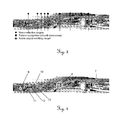
- FIG. 3 shows an image of a surveying environment with a representation of different target point types.
- An overview picture of the surveying environment is shown, which is provided by an overview camera mounted on the surveying instrument, into which symbols representing the verified target points are incorporated.
- three different kinds of target points are visualized, that is, retro-reflecting targets marked by a diamond symbol, a church cross marked by a full circle, which was recognized by pattern recognition, and an active, that is, a signal emitting target marked by a four pointed star.
- FIG. 4 shows another kind of presentation.
- the verified target points are marked by reticles 7 , 8 , 9 , 10 or by circles 11 , 12 , 13 .
- the size of the reticles 7 , 8 , 9 , 10 or circles 11 , 12 , 13 corresponds to the distance of the respective target points. That is, the closer the target point is located, the larger is the size of the reticle or circle, while more distant target points are represented by smaller reticles or circles.
- the target points may be detected over a whole defined surveying environment and/or within a predefined surveying area. Additionally, an area may be defined comprising all detected target points or comprising one type of target point in order to perform a precise measurement of these points.
- FIG. 5 two rectangle frames 15 , 17 are shown, wherein the position of the frames can be controlled by a user.
- the size of these frames 15 , 17 may be defined on basis of geometric values (e.g. horizontal angle ⁇ 10° and vertical angle) ⁇ 5° in order to scan an area within the frames.
- an area e.g. defined by one of the frames 15 , 17 may be excluded from the surveying environment.
- a sector 16 is defined corresponding to a determinable area of the surveying environment. Thereafter, the target point verification is carried out merely in the selected sector 16 but not in the entire surveying environment.
- additional target points can be selected by the user, or verified target points can be deselected, if they are not required.
- FIG. 6 An example for such a selection is shown in FIG. 6 .
- a circle 21 on the display which can be moved and positioned by the user, is used to chose a target point 19 for either selecting the same, in order to add it to the database or to deselect it, in order to remove it from the database.
- the user can deselect one of the other target points displayed in the image of FIG. 6 , if the respective target point is not required for the intended surveying process.
Landscapes
- Physics & Mathematics (AREA)
- Engineering & Computer Science (AREA)
- General Physics & Mathematics (AREA)
- Radar, Positioning & Navigation (AREA)
- Remote Sensing (AREA)
- Optical Radar Systems And Details Thereof (AREA)
- Length Measuring Devices By Optical Means (AREA)
Abstract
Description
- The invention relates to a target point recognition method and to a surveying instrument suitable to perform such a target point recognition method.
- In surveying it is known to use so called total stations for certain surveying methods. Therefore, the transformation of measurement data into an existing coordinate system is required. Such a transformation, for instance, can be done via measurement points that are already known beforehand.
- At present different laser signals are used for finding target points. While the surveying instrument moves, a horizontal position of a target point is detected with a first laser signal. Thereafter, a fine search is performed by using a different laser signal.
- There is need for a method capable to fast and reliably determine all available target points of a surveying environment fast and securely, as well as for a surveying instrument capable to perform the method.
- According to the invention, a target point recognition method for an automatic search of target points in a surveying environment in advance of a precise measurement of these points is provided, wherein an angle, in particular a horizontal and a vertical angle, to the target points is measured with a surveying instrument. Therein, the surveying instrument comprises means for measuring angles, a camera and processing means for data storing and controlling the following steps in an automated manner after starting the search:
- a scanning procedure with
-
- emitting electromagnetic radiation in form of a scanning beam, in particular in the form of a laser fan, to illuminate targets,
- moving the scanning beam within a predetermined angular range in order to scan the surveying environment,
- detecting reflections of the electromagnetic radiation on the targets, wherein the targets are defining the target points, and
- determining the angle to the target points,
- a capturing procedure with
-
- capturing an overall image of the surveying environment, wherein the overall image comprises at least one single image taken by the camera, in particular comprising several images stitched together to a panoramic view, and
- detecting target points and determining their angle on the overall image by image processing by matching targets with one or more predetermined search criteria,
- storing the target points together with their angle in a data base, and
- displaying the overall image together with marks for indicating a position of the target points detected within the scanning procedure and the capturing procedure in the overall image.
- Furthermore, the invention also relates to a surveying instrument, in particular a total station, comprising display means, a distance measuring unit, an angle determination unit, a camera for capturing images, and a processing unit for image processing, data storing and providing a searching functionality for searching for target points, that are defined by targets, and measuring an angle, in particular a horizontal and a vertical angle, to the target points in advance of a precise measurement of these target points. Therein—within the searching functionality—the processing unit is adapted to perform and control the following steps in an automated manner:
- a scanning procedure by use of scanning means with
-
- emitting electromagnetic radiation in form of a scanning beam, in particular in the form of a laser fan, to illuminate targets,
- moving the scanning beam within a predetermined angular range in order to scan the surveying environment,
- detecting reflections of the electromagnetic radiation on the targets, wherein the targets are defining the target points, and
- determining the angle to the target points,
- a capturing procedure with
-
- capturing an overall image of the surveying environment, wherein the overall image comprises at least one single image taken by the camera, in particular comprising several images stitched together to a panoramic view, and
- detecting target points and determining their angle on the overall image by image processing by matching targets with one or more predetermined search criteria,
- storing the target points together with their angle in a data base, and
- displaying the overall image together with marks for indicating a position of the target points detected within the scanning procedure and the capturing procedure in the overall image.
- Especially, the scanning means may comprise an electromagnetic radiation emitter for emitting a scanning beam, moving means for moving the scanning beam, a reflections detector for detecting reflections on the targets.
- Particularly, with other words, according to the invention, a target point recognition method comprises the steps of scanning a predetermined surveying environment, determining a possible target point, by matching the possible target point with predetermined search criteria, and storing the determined target point together with determined target point information in a data base. The determination of target points that are defined by targets, i.e. retro-reflecting targets or active targets, can be performed by a scanning procedure using a laser spread over a defined range forming a scanning beam, in particular in the form of a fan, and detecting reflections on targets and/or can be done by a capturing procedure using an image processing method after an image of the surveying environment is taken with a camera. By matching predefined pattern to the captured image additional targets can be determined. Performing of these steps is continued over the whole surveying environment. Both methods can be carried out at least partly overlapping in time and all determined targets or marks indicating the targets' position can be displayed on a display together with the image of the surveying environment.
- According to the target point recognition method of the invention and comparing it to prior art methods, an advantage is the possibility to recognize all targets and their target points, respectively, being in reach of the surveying instrument very fast within one initial process. Retro-reflecting targets are determined as well as signal-emitting targets or targets matching to a predefined pattern on an image. Furthermore, the determined and verified target points are stored in a data base for later use, in particularly for a precise measurement of angles and distance to the points. The capturing procedure, the scanning procedure, the data storing and the displaying may be controlled by processing means. Additionally, on the basis of information data of target points already known beforehand, it is possible to incorporate all found target points into an existing or into a new coordinate system and to display the target points in combination with an image corresponding to the surveying environment. Single target points can be added or deleted to or from the data base and with it a succeeding precise measurement can be performed faster.
- The execution of the recognition method should be explained roughly by means of one example. One wants to detect retro-reflecting targets and signal-emitting targets in a landscape. A surveying instrument, e.g. a total station, is positioned in the field and the target point recognition method is executed by pressing a button on the instrument or on a controller that is wirelessly connected to the instrument. After it, the instrument starts to scan the environment over a 360° angle or any other defined angular range with a laser fan and an automated target recognition sensor (ATR-sensor). Moreover, an image of the scanned environment is captured and an image processing method is further used for recognizing the top of a church tower as a target. Within this scan most of the targets are detected and their positions are displayed together with a panoramic image on the scanned environment. The user of the instrument defines an area on a display, in that a target is located but was not detected, yet, and the user starts the scan with other searching criteria in this area again. After the missing target was recognized now, the panoramic image together with all target points, each representing a target, is displayed. The user now chooses three points on the display he is interested in and starts a precise measurement of these points. The surveying instrument is directed automatically onto the selected points and performs the determination of the coordinates of these targets.
- In reach in the sense of the invention means not only visible by optical means, but can also pertain to non visible target points. Recognition of such target points can be based on acoustic and/or electromagnetic waves, e.g. on sound waves, ultra sound waves, radio waves.
- Particularly, the surveying environment can be scanned up to a 360° angle or up to a 180° angle for providing a panorama image or a partial hemisphere, in particular a full dome.
- Furthermore, predetermined search criteria can be defined and merely target points fulfilling the search criteria are verified. Thereby, particularly it is possible to exclude certain kinds of target points from the recognition process. Thereby a faster scanning and recognition of the desired kinds of target points is possible. The search criteria may be adapted to different sensors that are used with the recognition method.
- Particularly, furthermore, the determined target points can be displayed on a display. Thereby further processing of the target points by a user of the surveying instrument is possible. Especially it can be useful, if the determined and verified target points are displayed in combination with a virtual environment and/or in combination with an image of the surveying environment. Thereby, the target points and their relation to the surveying environment or their position in the surveying environment can be displayed.
- Furthermore, it can be advantageous, if the target points are displayed by using different symbols or marks. Depending on the sensor or the channel a target point is determined with, a corresponding mark can be used and, further, depending on the search criteria used for determining the respective target point other corresponding symbols can be used. Thus, particularly, it is facilitated to determine the kind of the target point on the display means. In addition, more information, e.g. pole height or reflector type, may be extracted from the image or determined on basis of backscattered pulses.
- It can be especially advantageous, if the size of a symbol used for representing the target point depends on the respective target points' distance from the used surveying instrument, i.e. the nearer a target point is to the surveying instrument, the bigger a mark representing this point is displayed.
- That means that the scanning procedure and the capturing procedure may be—as sub-procedures—part of a recognition process for detecting the target points, wherein the recognition process may further comprise other sub-procedures, in particular wherein the sub-procedures are performed by use of different sensor types, in particular an automatic-target-recognition-sensor, an over-view camera, an on-axes camera, a thermographical sensor and/or a range imaging module. Furthermore, the target points may be displayed in combination with a virtual environment and/or in combination with the overall image of the surveying environment, wherein the target points may be displayed by using different marks in dependency of the sub-procedure of the recognition process with which the target point has been recognised, especially in dependency of the search criteria used for determining the respective target point, in particular wherein the size of the representing marks may depend on the respective target points' distance from the surveying instrument.
- Additionally, it can be advantageous to manually verify possible target points. These can then be added to the data base. Thus, it is possible to define additional target points. Additionally or alternatively, some or all verified target points can be manually chosen and then removed from the data base. Thus, target points not necessary for the surveying task to be performed can be excluded. For instance, it might be useful to pick only one target point from a group of closely arranged and similar target points. Thereby, choosing a wrong target point in a later stage of the surveying process can be avoided.
- In order to perform the above mentioned manual control, control means such as a keyboard, a control stick, a touch display or a combination thereof can be provided at the surveying instrument and/or at a remote control for the surveying instrument.
- Particularly, the scanning of the surveying environment can be performed by laser signals. Alternatively scanning by light signals, optical or opto-electronic scanning or any combination of some or all of these scanning techniques can be performed.
- Particularly, target point information of some or all of the verified target points can be transferred into an existing coordinate system. Thereby, the processing of the found target points can be advanced.
- Particularly, furthermore, the search criteria are chosen to enable verification whether a target point is a retro-reflecting target and/or a signal-emitting target and/or a target representing a predetermined structure or pattern and/or a temporarily-signalized target and/or a coded target and/or a half-corresponding target. These are some of the most common possible kinds of targets. However, the search criteria can be chosen to fit any arbitrary kind of target point.
- Particularly, the scan within the target point recognition method can be repeated several times by using different types of sensors or search criteria. In case of a first sensor is not able to recognize a type of a target correctly another sensor or other search criteria may be used in an additional scan suited for the target type.
- A surveying instrument according to the invention comprises scanning means which are designed to scan a surveying environment and determining means which are designed to determine one or more possible target points in the scanned surveying environment. Furthermore, verifying means are provided to verify whether the one or the more possible target points matches with one or more predetermined search criteria. Thereafter, the determined and/or verified target points together with target point information are stored in storing means.
- Furthermore, the surveying instrument may comprise image capturing means, e.g. a camera, for capturing an image of the scanned surveying environment. It can comprise display means for displaying the measuring environment virtually, e.g. as a sphere or a CAD environment, and/or in the form of an image as well. Thereby, particularly an image of the surveying environment together with the determined target points can be displayed on the display means. With additional operating means for manually selecting and/or deselecting target points a user of the surveying instrument might then manually add further target points or remove unwanted target points from the data base.
- That means that the surveying instrument, in particular a total station, comprises display means, scanning means for emitting electromagnetic radiation in form of a scanning beam and for detecting reflections, a distance measuring unit, an angle determination unit, a camera for capturing images, a processing unit for image processing, data storing and providing a searching functionality for searching for target points, that are defined by targets, and measuring an angle, in particular a horizontal and a vertical angle, to the target points in advance of a precise measurement of these target points, wherein—within the searching functionality—the processing unit is adapted to perform respectively control a recognition process in an automated manner.
- A surveying instrument according to the invention particularly enables to scan the whole surveying environment and automatically determines target points if they correspond to predetermined search criteria. The determination of target points can be done with a sensor scanning a surveying environment and determining reflections of electromagnetic radiation for target identification and/or can be performed by image processing methods on an overall image of the surveying environment, wherein the overall image can be stitched from at least two partial images of the environment. Thereafter, it may be verified whether the target points are true target points. These verified target points can then be stored together with corresponding target point information such as distance, angle, and elevation etc. of the respective target point with regard to the surveying instrument. The overall image may be displayed on display means together with marks for indicating the positions of the target points in the image.
- Particularly, the scanning means may comprise one or more laser scanners.
- Among the sensors used for the method can be at least a sensor intend for the scanning procedure with emitting electromagnetic radiation spread over a defined range forming a scanning beam, in particular in the form of a fan, moving the scanning beam within an angular range in order to scan the surveying environment, detecting reflections of the electromagnetic radiation on the targets and determining a rough angle, in particular the horizontal and the vertical angle, to the target points (power-search-sensor) in advance of a precise measurement. Additionally, an over-view camera with a low or no magnification factor and thereby comprising a large field of view or an ATR-sensor (automatic target recognition sensor) can be used. For an ATR-detection radiation is emitted in the direction of an aiming axis, is reflected at a prism and detected by the ATR-sensor. According to the position the reflected radiation hits the sensors the direction to the target can be determined.
- Further the surveying environment can be defined by moving the fanned radiation over a predetermined angular range with the scanned area corresponding to the surveying environment. On the other hand, a defined surveying environment can be scanned by adapting the movement of the fan to an angular range of the surveying environment.
- Other advantages and details of the invention will be appreciated from the following description of presently preferred embodiments together with the attached drawings.
- In the drawings:
-
FIG. 1 is a schematic view of a principle of a search process for target points and subsequent representation of the found target points, -
FIG. 2 is a schematic chart of a target point finding process according to the invention, -
FIG. 3 is an image of a surveying environment with a representation of different target point types, -
FIG. 4 is an image of the surveying environment ofFIG. 3 with a representation of different target points depending on their distance, -
FIG. 5 is an image of the surveying environment ofFIG. 3 with a selection/deselection mask for manually selecting or deselecting target points, -
FIG. 6 is an image of the surveying environment ofFIG. 3 with a picking tool for choosing certain target points. - Presently preferred embodiments of the invention will be described on the basis of the Figures.
-
FIG. 1 is a schematic view of a principle of a search process for target points and subsequent representation of the found target points. A surveyinginstrument 1 according to the invention is placed in a surveying environment. Thereafter, an initial scan is triggered. The scan may be performed with a 360° angle in order to provide a full panoramic view. - During the scan, various sensors provided in the
surveying instrument 1 provide signals to a controller. Among the sensors used can be an over-view camera, a power-search-sensor (PS-sensor) capable to recognize reflected signals and/or an automatic-target-recognition-sensor (ATR-sensor). Based on the signals from the respective sensor, by using predetermined search criteria, the controller verifies whether a scanned point is a target point. For instance, if the over-view camera provides an image signal of the tip of thepower mast 2, by using picture recognizing software, the controller verifies whether the image corresponds to one of plural image patterns stored in a data base, that is, to the pattern of a power mast tip (capturing procedure). Thereafter, the target point is stored in a data base, and is presented on a display which is provided at the total station. Depending on the kind of the target point, the target point symbol on the display varies. - Due to the various search criteria stored in the data base, the controller is capable to recognize plural different kinds of targets such as
signal emitting targets 3, retroreflective targets house gable 5, a church cross, thepower mast tip 2, a window corner etc. - In
FIG. 1 the verifiedtarget points 2′, 3′, 4 a′, 4 b′, 4 c′, 5′ corresponding to theirtargets -
FIG. 2 is a schematic chart showing a target point finding process according to an embodiment of the invention. According to this embodiment, after initiating the target search the surveying environment is scanned by a first sensor being a CCD-sensor of an on-axis-camera, a second sensor being a PS-sensor, and an automatic-target-recognition-camera-sensor (ATR-sensor). InFIG. 2 , other sensors which can be used with the method and surveying instrument according to the invention are represented by Sensor n. - In a next step, the signals received from these sensors are verified with regard to predetermined search criteria A, B, C or D. If one of these search criteria is fulfilled, the respective target point together with information pertaining the target points' distance, elevation, angle, etc. is stored in a data base. The value for this angle may not be a precise value but a result of a rough measurement in advance of a precise measurement. Depending on the fulfilled search criteria, the kind of the target point is stored as well.
- Since the surveying instrument in addition to a CCD-sensor can be provided with a PS-sensor or an ATR-sensor, the position of retro-reflective targets can be determined.
- Among the most common target points there are retro-reflecting targets, signal-emitting targets and temporarily signalized targets such as an object onto which a laser dot is projected, which all can be detected using the scanning procedure, further, targets representing a certain structure or pattern such as church crosses, window corners, power line masts, and half-corresponding targets such as a normal sticker that is not reflective, that can be determined with the capturing procedure and, moreover, there are coded targets such as a retro-reflecting target combined with, e.g. a bar code, which can be determined with both procedures.
- In addition to storing the verified target point, the target point is displayed on display means of the surveying instrument depending on predetermined displaying criteria. For displaying a virtual presentation as the one in
FIG. 1 or an image presentation as the one inFIG. 3 are presently preferred. -
FIG. 3 shows an image of a surveying environment with a representation of different target point types. An overview picture of the surveying environment is shown, which is provided by an overview camera mounted on the surveying instrument, into which symbols representing the verified target points are incorporated. In the image ofFIG. 3 , three different kinds of target points are visualized, that is, retro-reflecting targets marked by a diamond symbol, a church cross marked by a full circle, which was recognized by pattern recognition, and an active, that is, a signal emitting target marked by a four pointed star. -
FIG. 4 shows another kind of presentation. InFIG. 4 the verified target points are marked byreticles circles reticles circles - In
FIG. 5 two rectangle frames 15, 17 are shown, wherein the position of the frames can be controlled by a user. The size of theseframes frames sector 16 is defined corresponding to a determinable area of the surveying environment. Thereafter, the target point verification is carried out merely in the selectedsector 16 but not in the entire surveying environment. Furthermore, in the selectedsector 16, additional target points can be selected by the user, or verified target points can be deselected, if they are not required. In order to facilitate the selection/deselection, it is possible to digitally or optically magnify the selectedsector 16 and to display this magnified image on the display of the total station, on a second alternative display or on both displays, upon a command from the user. - An example for such a selection is shown in
FIG. 6 . Here acircle 21 on the display, which can be moved and positioned by the user, is used to chose atarget point 19 for either selecting the same, in order to add it to the database or to deselect it, in order to remove it from the database. Similarly, the user can deselect one of the other target points displayed in the image ofFIG. 6 , if the respective target point is not required for the intended surveying process. - Due to the automatic target point recognition method, a time consuming prism search by the user can be avoided. Furthermore, since the target points are automatically selected, an erroneous aiming at an incorrect target point can be avoided, because all possible target points are detected before the surveying process begins. However, a correction with respect to adding or removing certain target points is nevertheless still possible.
Claims (21)
Applications Claiming Priority (4)
| Application Number | Priority Date | Filing Date | Title |
|---|---|---|---|
| EP10168772 | 2010-07-07 | ||
| EP10168772A EP2405237A1 (en) | 2010-07-07 | 2010-07-07 | Target Point Recognition Method and Surveying Instrument |
| EP10168772.1 | 2010-07-07 | ||
| PCT/EP2011/061500 WO2012004342A1 (en) | 2010-07-07 | 2011-07-07 | Target point recognition method and surveying instrument |
Publications (2)
| Publication Number | Publication Date |
|---|---|
| US20120249783A1 true US20120249783A1 (en) | 2012-10-04 |
| US9046361B2 US9046361B2 (en) | 2015-06-02 |
Family
ID=43533164
Family Applications (1)
| Application Number | Title | Priority Date | Filing Date |
|---|---|---|---|
| US13/515,438 Active 2032-06-30 US9046361B2 (en) | 2010-07-07 | 2011-07-07 | Target point recognition method and surveying instrument |
Country Status (7)
| Country | Link |
|---|---|
| US (1) | US9046361B2 (en) |
| EP (2) | EP2405237A1 (en) |
| KR (1) | KR101498148B1 (en) |
| CN (1) | CN102985789B (en) |
| BR (1) | BR112013000410A2 (en) |
| CA (1) | CA2801668C (en) |
| WO (1) | WO2012004342A1 (en) |
Cited By (3)
| Publication number | Priority date | Publication date | Assignee | Title |
|---|---|---|---|---|
| US20130050474A1 (en) * | 2010-05-10 | 2013-02-28 | Leica Geosystems Ag | Surveying method |
| US20160349049A1 (en) * | 2015-06-01 | 2016-12-01 | Leica Geosystems Ag | Target point detection method |
| CN115131878A (en) * | 2022-08-30 | 2022-09-30 | 深圳市心流科技有限公司 | Method, device, terminal and storage medium for determining motion of intelligent artificial limb |
Families Citing this family (9)
| Publication number | Priority date | Publication date | Assignee | Title |
|---|---|---|---|---|
| US9222771B2 (en) | 2011-10-17 | 2015-12-29 | Kla-Tencor Corp. | Acquisition of information for a construction site |
| US8988663B2 (en) * | 2013-01-22 | 2015-03-24 | Raytheon Company | Laser range finding |
| US9518822B2 (en) * | 2013-09-24 | 2016-12-13 | Trimble Navigation Limited | Surveying and target tracking by a network of survey devices |
| EP3034995B1 (en) | 2014-12-19 | 2024-02-28 | Leica Geosystems AG | Method for determining a position and orientation offset of a geodetic surveying device and corresponding measuring device |
| JP2016213810A (en) * | 2015-05-01 | 2016-12-15 | 株式会社リコー | Image display system, information processing apparatus, program, and image display method |
| US11029263B2 (en) | 2015-12-09 | 2021-06-08 | Integrated-X, Inc. | Systems and methods for inspection using electromagnetic radiation |
| EP3614173B1 (en) | 2018-08-20 | 2025-11-26 | Leica Geosystems AG | Surveying device with automatic training of locked object or person for camera based target tracking |
| CN112419405B (en) * | 2019-08-23 | 2024-03-08 | 杭州海康威视数字技术股份有限公司 | A target tracking joint display method, security system and electronic equipment |
| CN114071005B (en) * | 2020-08-07 | 2022-12-27 | 华为技术有限公司 | Object detection method, electronic device and computer-readable storage medium |
Citations (7)
| Publication number | Priority date | Publication date | Assignee | Title |
|---|---|---|---|---|
| US20050046584A1 (en) * | 1992-05-05 | 2005-03-03 | Breed David S. | Asset system control arrangement and method |
| US20050099637A1 (en) * | 1996-04-24 | 2005-05-12 | Kacyra Ben K. | Integrated system for quickly and accurately imaging and modeling three-dimensional objects |
| US7209221B2 (en) * | 1994-05-23 | 2007-04-24 | Automotive Technologies International, Inc. | Method for obtaining and displaying information about objects in a vehicular blind spot |
| US20080205707A1 (en) * | 2005-01-14 | 2008-08-28 | Leica Geosystems Ag | Method And Geodetic Device For Surveying At Least One Target |
| US7477758B2 (en) * | 1992-05-05 | 2009-01-13 | Automotive Technologies International, Inc. | System and method for detecting objects in vehicular compartments |
| US20090092284A1 (en) * | 1995-06-07 | 2009-04-09 | Automotive Technologies International, Inc. | Light Modulation Techniques for Imaging Objects in or around a Vehicle |
| US20100141775A1 (en) * | 2003-12-16 | 2010-06-10 | Michael Vogel | Calibration of a surveying instrument |
Family Cites Families (4)
| Publication number | Priority date | Publication date | Assignee | Title |
|---|---|---|---|---|
| EP1517117A1 (en) | 2003-09-22 | 2005-03-23 | Leica Geosystems AG | Method and system for the determination of the actual position of a positioning apparatus |
| EP1610091A1 (en) | 2004-06-23 | 2005-12-28 | Leica Geosystems AG | Scanner system and method for surface acquisition |
| JP5469894B2 (en) * | 2008-07-05 | 2014-04-16 | 株式会社トプコン | Surveying device and automatic tracking method |
| EP2194399A1 (en) * | 2008-12-03 | 2010-06-09 | Leica Geosystems AG | Position determination procedure and geodata measuring system |
-
2010
- 2010-07-07 EP EP10168772A patent/EP2405237A1/en not_active Withdrawn
-
2011
- 2011-07-07 CN CN201180033523.0A patent/CN102985789B/en active Active
- 2011-07-07 EP EP11732423.6A patent/EP2591314B1/en active Active
- 2011-07-07 WO PCT/EP2011/061500 patent/WO2012004342A1/en not_active Ceased
- 2011-07-07 US US13/515,438 patent/US9046361B2/en active Active
- 2011-07-07 BR BR112013000410A patent/BR112013000410A2/en active Search and Examination
- 2011-07-07 CA CA2801668A patent/CA2801668C/en not_active Expired - Fee Related
- 2011-07-07 KR KR1020137001371A patent/KR101498148B1/en not_active Expired - Fee Related
Patent Citations (7)
| Publication number | Priority date | Publication date | Assignee | Title |
|---|---|---|---|---|
| US20050046584A1 (en) * | 1992-05-05 | 2005-03-03 | Breed David S. | Asset system control arrangement and method |
| US7477758B2 (en) * | 1992-05-05 | 2009-01-13 | Automotive Technologies International, Inc. | System and method for detecting objects in vehicular compartments |
| US7209221B2 (en) * | 1994-05-23 | 2007-04-24 | Automotive Technologies International, Inc. | Method for obtaining and displaying information about objects in a vehicular blind spot |
| US20090092284A1 (en) * | 1995-06-07 | 2009-04-09 | Automotive Technologies International, Inc. | Light Modulation Techniques for Imaging Objects in or around a Vehicle |
| US20050099637A1 (en) * | 1996-04-24 | 2005-05-12 | Kacyra Ben K. | Integrated system for quickly and accurately imaging and modeling three-dimensional objects |
| US20100141775A1 (en) * | 2003-12-16 | 2010-06-10 | Michael Vogel | Calibration of a surveying instrument |
| US20080205707A1 (en) * | 2005-01-14 | 2008-08-28 | Leica Geosystems Ag | Method And Geodetic Device For Surveying At Least One Target |
Non-Patent Citations (1)
| Title |
|---|
| Bhanu, "Automatic Target Recognition: State of the Art Survey," IEEE Trans. on Aerospace and Electronic Systems, vol. AES-22, no. 4, July 1986, pp. 364-379. * |
Cited By (5)
| Publication number | Priority date | Publication date | Assignee | Title |
|---|---|---|---|---|
| US20130050474A1 (en) * | 2010-05-10 | 2013-02-28 | Leica Geosystems Ag | Surveying method |
| US9109890B2 (en) * | 2010-05-10 | 2015-08-18 | Leica Geosystems Ag | Surveying method |
| US20160349049A1 (en) * | 2015-06-01 | 2016-12-01 | Leica Geosystems Ag | Target point detection method |
| US9970762B2 (en) * | 2015-06-01 | 2018-05-15 | Leica Geosystems Ag | Target point detection method |
| CN115131878A (en) * | 2022-08-30 | 2022-09-30 | 深圳市心流科技有限公司 | Method, device, terminal and storage medium for determining motion of intelligent artificial limb |
Also Published As
| Publication number | Publication date |
|---|---|
| KR20130027553A (en) | 2013-03-15 |
| US9046361B2 (en) | 2015-06-02 |
| WO2012004342A1 (en) | 2012-01-12 |
| EP2591314B1 (en) | 2015-04-01 |
| AU2011275724A1 (en) | 2012-12-13 |
| KR101498148B1 (en) | 2015-03-04 |
| CN102985789A (en) | 2013-03-20 |
| CA2801668C (en) | 2017-01-10 |
| EP2405237A1 (en) | 2012-01-11 |
| BR112013000410A2 (en) | 2016-05-17 |
| CN102985789B (en) | 2015-05-13 |
| EP2591314A1 (en) | 2013-05-15 |
| CA2801668A1 (en) | 2012-01-12 |
Similar Documents
| Publication | Publication Date | Title |
|---|---|---|
| US9046361B2 (en) | Target point recognition method and surveying instrument | |
| CN101932905B (en) | Localization of a surveying instrument in relation to a ground mark | |
| JP7313955B2 (en) | Surveying instrument, surveying method and surveying program | |
| US11629957B2 (en) | Surveying apparatus | |
| JP4971344B2 (en) | Surveying method and surveying device | |
| KR101455726B1 (en) | Surveying method and Surveying Instrument | |
| EP1347267A1 (en) | Surveying instrument and method for acquiring image data by using the surveying instrument. | |
| US20080075325A1 (en) | Position measuring system, position measuring method and position measuring program | |
| CN101545770A (en) | Surveying system | |
| US20110043620A1 (en) | Determining coordinates of a target in relation to a survey instrument having at least two cameras | |
| CN103635777B (en) | For the structure measurement unit at the edge and corner of following the trail of, measure and mark adjacently situated surfaces | |
| US11475231B2 (en) | Survey system and survey method | |
| CN111397586B (en) | Measurement system and method for verifying pre-configured target attributes using the same | |
| JP7511049B2 (en) | Surveying equipment, surveying method, and surveying program | |
| AU2011275724B2 (en) | Target point recognition method and surveying instrument | |
| EP2240741A1 (en) | Localizing a surveying instrument in relation to a ground mark | |
| JP2021021608A (en) | Surveying system | |
| US20240201373A1 (en) | Measurement system with automatic tracking for customizing swimming pool components | |
| EP1896897B1 (en) | Method, device, and program product for visually indicating a selected object, using a device equipped with camera |
Legal Events
| Date | Code | Title | Description |
|---|---|---|---|
| AS | Assignment |
Owner name: LEICA GEOSYTEMS AG, SWITZERLAND Free format text: ASSIGNMENT OF ASSIGNORS INTEREST;ASSIGNORS:NINDL, DANIEL;ZOGG, HANS-MARTIN;LIENHART, WERNER;AND OTHERS;SIGNING DATES FROM 20120326 TO 20120502;REEL/FRAME:028363/0688 |
|
| STCF | Information on status: patent grant |
Free format text: PATENTED CASE |
|
| FEPP | Fee payment procedure |
Free format text: PAYOR NUMBER ASSIGNED (ORIGINAL EVENT CODE: ASPN); ENTITY STATUS OF PATENT OWNER: LARGE ENTITY |
|
| MAFP | Maintenance fee payment |
Free format text: PAYMENT OF MAINTENANCE FEE, 4TH YEAR, LARGE ENTITY (ORIGINAL EVENT CODE: M1551); ENTITY STATUS OF PATENT OWNER: LARGE ENTITY Year of fee payment: 4 |
|
| MAFP | Maintenance fee payment |
Free format text: PAYMENT OF MAINTENANCE FEE, 8TH YEAR, LARGE ENTITY (ORIGINAL EVENT CODE: M1552); ENTITY STATUS OF PATENT OWNER: LARGE ENTITY Year of fee payment: 8 |