US20120249679A1 - Apparatus for printing surfaces having a plurality of movable print heads and system having the apparatus - Google Patents
Apparatus for printing surfaces having a plurality of movable print heads and system having the apparatus Download PDFInfo
- Publication number
- US20120249679A1 US20120249679A1 US13/432,235 US201213432235A US2012249679A1 US 20120249679 A1 US20120249679 A1 US 20120249679A1 US 201213432235 A US201213432235 A US 201213432235A US 2012249679 A1 US2012249679 A1 US 2012249679A1
- Authority
- US
- United States
- Prior art keywords
- print head
- nozzles
- printing
- heads
- Prior art date
- Legal status (The legal status is an assumption and is not a legal conclusion. Google has not performed a legal analysis and makes no representation as to the accuracy of the status listed.)
- Granted
Links
Images


Classifications
-
- B—PERFORMING OPERATIONS; TRANSPORTING
- B41—PRINTING; LINING MACHINES; TYPEWRITERS; STAMPS
- B41J—TYPEWRITERS; SELECTIVE PRINTING MECHANISMS, i.e. MECHANISMS PRINTING OTHERWISE THAN FROM A FORME; CORRECTION OF TYPOGRAPHICAL ERRORS
- B41J2/00—Typewriters or selective printing mechanisms characterised by the printing or marking process for which they are designed
- B41J2/22—Typewriters or selective printing mechanisms characterised by the printing or marking process for which they are designed characterised by selective application of impact or pressure on a printing material or impression-transfer material
- B41J2/23—Typewriters or selective printing mechanisms characterised by the printing or marking process for which they are designed characterised by selective application of impact or pressure on a printing material or impression-transfer material using print wires
- B41J2/235—Print head assemblies
- B41J2/25—Print wires
-
- B—PERFORMING OPERATIONS; TRANSPORTING
- B05—SPRAYING OR ATOMISING IN GENERAL; APPLYING FLUENT MATERIALS TO SURFACES, IN GENERAL
- B05B—SPRAYING APPARATUS; ATOMISING APPARATUS; NOZZLES
- B05B1/00—Nozzles, spray heads or other outlets, with or without auxiliary devices such as valves, heating means
- B05B1/14—Nozzles, spray heads or other outlets, with or without auxiliary devices such as valves, heating means with multiple outlet openings; with strainers in or outside the outlet opening
- B05B1/16—Nozzles, spray heads or other outlets, with or without auxiliary devices such as valves, heating means with multiple outlet openings; with strainers in or outside the outlet opening having selectively- effective outlets
- B05B1/169—Nozzles, spray heads or other outlets, with or without auxiliary devices such as valves, heating means with multiple outlet openings; with strainers in or outside the outlet opening having selectively- effective outlets having three or more selectively effective outlets
-
- B—PERFORMING OPERATIONS; TRANSPORTING
- B05—SPRAYING OR ATOMISING IN GENERAL; APPLYING FLUENT MATERIALS TO SURFACES, IN GENERAL
- B05B—SPRAYING APPARATUS; ATOMISING APPARATUS; NOZZLES
- B05B13/00—Machines or plants for applying liquids or other fluent materials to surfaces of objects or other work by spraying, not covered by groups B05B1/00 - B05B11/00
- B05B13/002—Machines or plants for applying coating liquids or other fluent materials by inkjet
-
- B—PERFORMING OPERATIONS; TRANSPORTING
- B41—PRINTING; LINING MACHINES; TYPEWRITERS; STAMPS
- B41J—TYPEWRITERS; SELECTIVE PRINTING MECHANISMS, i.e. MECHANISMS PRINTING OTHERWISE THAN FROM A FORME; CORRECTION OF TYPOGRAPHICAL ERRORS
- B41J2/00—Typewriters or selective printing mechanisms characterised by the printing or marking process for which they are designed
- B41J2/005—Typewriters or selective printing mechanisms characterised by the printing or marking process for which they are designed characterised by bringing liquid or particles selectively into contact with a printing material
- B41J2/01—Ink jet
- B41J2/135—Nozzles
- B41J2/165—Prevention or detection of nozzle clogging, e.g. cleaning, capping or moistening for nozzles
-
- B—PERFORMING OPERATIONS; TRANSPORTING
- B41—PRINTING; LINING MACHINES; TYPEWRITERS; STAMPS
- B41J—TYPEWRITERS; SELECTIVE PRINTING MECHANISMS, i.e. MECHANISMS PRINTING OTHERWISE THAN FROM A FORME; CORRECTION OF TYPOGRAPHICAL ERRORS
- B41J3/00—Typewriters or selective printing or marking mechanisms characterised by the purpose for which they are constructed
- B41J3/407—Typewriters or selective printing or marking mechanisms characterised by the purpose for which they are constructed for marking on special material
- B41J3/4073—Printing on three-dimensional objects not being in sheet or web form, e.g. spherical or cubic objects
-
- B—PERFORMING OPERATIONS; TRANSPORTING
- B41—PRINTING; LINING MACHINES; TYPEWRITERS; STAMPS
- B41J—TYPEWRITERS; SELECTIVE PRINTING MECHANISMS, i.e. MECHANISMS PRINTING OTHERWISE THAN FROM A FORME; CORRECTION OF TYPOGRAPHICAL ERRORS
- B41J3/00—Typewriters or selective printing or marking mechanisms characterised by the purpose for which they are constructed
- B41J3/54—Typewriters or selective printing or marking mechanisms characterised by the purpose for which they are constructed with two or more sets of type or printing elements
- B41J3/543—Typewriters or selective printing or marking mechanisms characterised by the purpose for which they are constructed with two or more sets of type or printing elements with multiple inkjet print heads
Definitions
- the present invention relates to an apparatus for printing surfaces, including a plurality of movable print heads each including a plurality of individually actuable nozzles, at least one printing position and at least one parking position for the print heads, in which the print heads are movable into the respective positions.
- the invention also relates to a system having the apparatus.
- So-called inkjet printers having movable inkjet print heads are known from the prior art. Those inkjet printers are used, for example, in the home and office areas, in order to print paper with multiple colors. In that case, a separate print head is available for each printing color.
- the individual print heads and/or their respective nozzle configurations are identical.
- the heads are moved at the same time relative to the paper and in the process eject ink droplets at the same time, that is to say all of the heads are active. After the printing, all of the print heads are moved into a common parking position, in which usually cleaning of the heads also takes place, that is to say all of the heads are inactive.
- inkjet heads are also known, in which the heads are accommodated, for example, on large X-Y frames and are used to print large area paper sheets or material webs.
- inkjet heads it is also already known to attach inkjet heads to robot arms which can be moved freely in three dimensions, in order for it to be possible in that way to print not only flat but also curved surfaces (as desired), for example body parts of vehicles.
- spray nozzles are usually used, that is to say the parts are loaded with a spray mist.
- spray nozzles of that type cannot eject individual droplets as a result of individual control pulses.
- German Patent DE 41 20 293 C2 describes a rotatable inkjet head (having individually actuable nozzles, for example according to the piezoelectric principle) on an X-Y frame, with which curves of any desired profile can be printed with a consistent coat thickness.
- a corresponding number of heads which are, however, identical can also be provided for multiple-color printing (yellow, cyan, magenta, black).
- German Patent Application DE 10 2008 053 178 A1 corresponding to U.S. Patent Application Publication No. US 2011/0262622 A1
- a coating device for example for body parts of vehicles, with an inkjet head (having individually actuable nozzles, for example according to the piezoelectric principle) being accommodated on a robot arm and therefore making it possible to move it into any desired position and along any desired tracks.
- the print head can have a part which ejects the coating medium continuously and a part which ejects it in droplets.
- the print head can also have nozzle openings of different size, for example nozzle rows with large nozzles and nozzle rows with small nozzles.
- a plurality of identical print heads can also be provided which can be pivoted relative to one another, in order to achieve an improved adaptation to the surface of a curved component (see FIG. 22 of German Patent Application DE 10 2008 053 178 A1, corresponding to U.S. Patent Application Publication No. US 2011/0262622 A1).
- European Patent Application EP 970 811 A1 corresponding to U.S. Pat. No. 6,096,132, describes an automatic painting device for vehicles, which automatic painting device has spray pistols for four colors.
- the four identical spray pistols are accommodated on an X-Y frame in such a way that they can have their respective spacing in the Z-direction from the vehicle surface changed individually.
- identical heads that is to say identical nozzle configurations
- all of the heads are always active at the same time and print, or are inactive and do not print.
- the adaptation to the surface of a curved component takes place only by guiding the head to the component and guiding it along the component while maintaining the spacing, or by relative positioning of a plurality of heads with respect to one another.
- the printing of extremely curved surfaces (with small radii of curvature) and, in particular, of surfaces with so-called undercuts (with surface sections which project freely and impede, for example, the free access to other surface sections) can therefore still lead to problems.
- a further problem can result from the dimensions of the print head.
- an inkjet print head having a length L at a given working spacing A from the surface to be printed and a given tolerance TA of the working spacing, only a surface with a minimum radius of curvature Rmin can be printed due to the geometric conditions (L and A: see FIG. 1 ).
- Rmin increases as L increases and decreases as TA increases.
- Rmin is independent of A.
- A has therefore been estimated with an appropriate value of 10 mm.
- Rmin is actually dependent on A after all because it cannot be expected that a print head can achieve the same print resolution at every spacing A from the surface, and therefore Rmin decreases as A increases (at a given print resolution).
- an apparatus for printing surfaces comprises at least one printing position and at least one parking position, a plurality of movable print heads configured to be moved into the at least one printing position and into the at least one parking position, each of the movable print heads having a plurality of individually actuable nozzles, the movable print heads including at least one first print head and at least one second print head having mutually different nozzle configurations, the at least one first print head being disposed in a printing position and the at least one second print head being disposed in a parking position, in a first mode, and the at least one first print head being disposed in a parking position and the at least one second print head being disposed in a printing position, in a second mode.
- the surfaces to be printed are preferably surfaces which are shaped in any desired manner and, in particular, are curved to as pronounced an extent as desired. They can also have undercuts.
- the precondition is provided to print both, for example, flat surface sections and (severely) curved surface sections.
- surfaces with surface sections which are different in terms of their respective topology can also be printed.
- nozzle configuration is used locally in this case which is provided for flat, curved or severely curved sections or for sections with undercuts.
- the apparatus therefore permits a change between heads, that is to say it can be defined which head with which nozzle configuration is to be active and which is to be inactive.
- the heads can preferably be moved freely three-dimensionally and can therefore advantageously be guided onto surfaces (surface sections) which are shaped in any desired manner and can be guided along the surfaces (surface sections) on tracks which are shaped in any desired manner.
- a predefined working spacing from surfaces which are shaped in any desired manner can also be maintained.
- the nozzles are preferably inkjet nozzles which produce droplets in a one-dimensional or two-dimensional configuration.
- the nozzles are preferably not nozzles which generate spray mist or are different from nozzles of that type.
- the parking positions can be identical for the different print heads. As an alternative, a separate parking position can also be provided for each print head. Corresponding conditions apply to the printing position/positions.
- the nozzle configurations which are different from one another differ in terms of their respective number of nozzles, with the number of nozzles of the nozzle configuration of the first print head being lower than the number of nozzles of the nozzle configuration of the second print head.
- one print head can have more than ten nozzles and one print head can have less than ten nozzles.
- the expressions “rapid” and “slow” do not relate to the relative speed between the substrate and the nozzles, but rather to the printed area per unit time—that is to say, for example, using the unit square meters per minute.
- the nozzle configurations which are different from one another differ in terms of their respective spatial configuration of the nozzles.
- one print head can have a noncurved, linear nozzle configuration and one print head can have a curved (curvilinear), linear nozzle configuration.
- the nozzle configuration can be hook-shaped and can therefore be used for printing edges or bends.
- At least one first and one second print head are disposed on a common transport apparatus which moves the print heads into the respective positions.
- a transport apparatus which moves the print heads into the respective positions.
- an active print head can be moved into a parking position and an inactive print head can be moved into a printing position, with the activity states changing.
- the transport apparatus is preferably a rotation apparatus which permits the individual print heads that are accommodated on it to have their respective position (and activity states) changed by rotation.
- a circulating belt or a (for example, electric) linear drive can be provided.
- the common transport apparatus is disposed on a controllable and multiple-member robot arm or an X-Y-Z frame, with X, Y and Z denoting the three spatial directions, in which the transport apparatus can be moved independently of one another through the use of the frame.
- FIG. 1 is a diagrammatic, partly sectional, side-elevational view of one preferred exemplary embodiment of an apparatus according to the invention for printing surfaces;
- FIG. 2 is a fragmentary, partly sectional, side-elevational view showing a situation during the printing of undercuts
- FIG. 3 is an enlarged, partly sectional, side-elevational view of a further preferred exemplary embodiment of an apparatus according to the invention for printing surfaces;
- FIGS. 4A-4E are fragmentary, perspective views of preferred exemplary embodiments of apparatuses according to the invention.
- FIG. 1 a diagrammatic side view of one preferred exemplary embodiment of an apparatus 2 according to the invention for printing surfaces 1 that are shaped in any desired manner (which are referred to in short as 3D surfaces).
- the surface 1 has at least one curvature.
- the surface can, for example, be a vehicle body part to be painted. It is possible, by way of the apparatus 2 according to the invention, to paint surfaces which are curved or shaped in any desired manner with one color or multiple colors, or to provide them with a multiple-color information item (image, pattern or text).
- the apparatus 2 has a plurality of movable print heads 3 a to 3 c of different geometry which in each case include a plurality of individually actuable nozzles 4 a to 4 c .
- three print heads are shown by way of example.
- Each of the three print heads can be moved into an (active) printing position 5 a or an (inactive) parking position 5 b or 5 c .
- the printing position 5 a is a position in which the print head 3 a is disposed within a tolerance TA at a working spacing A from the surface 1 . If so-called inkjet heads are used, the working spacing can be limited, for example, by their operating range, that is to say the substantially unimpeded range of the ink droplets.
- the working spacing can also be limited by a minimum spacing, for example in order to avoid collision.
- the print head 3 a is in the printing position 5 a
- the two print heads 3 b and 3 c are in respective parking positions 5 b and 5 c .
- the parking position is a position, in which the print head does not print and instead can be cleaned, for example. The cleaning of the inactive print head can take place while the active print head is printing.
- the three print heads 3 a - c are disposed on a common transport apparatus 6 which is configured as a rotation apparatus 7 (see arrow 7 ′) and moves or rotates the print heads 3 a - c into the respective positions 5 a - c .
- a rotation apparatus 7 see arrow 7 ′
- more than three or only two print heads can be provided.
- Each individual print head 3 a - c can in turn be accommodated rotatably on the rotation apparatus 7 (see arrow 7 ′′).
- a rotation 7 ′ through 120° counter to the clockwise direction moves the first (active) print head 3 a out of the printing position 5 a into the parking position 5 c and moves the second (inactive) print head 3 b out of the parking position 5 b into the printing position 5 a (the second print head then becomes active and the first print head becomes inactive).
- the third print head 3 c changes between the two parking positions 5 c and 5 b .
- the rotation apparatus 7 can have a rotatable, central carrier 8 for the number of print heads. The rotation can take place through the use of an electric motor or pneumatically. A rotation which is only back and forth can also be provided instead of a rotation through 360° or more.
- the use of the rotation apparatus permits rapid and precise changes to be used between the respective print heads, in particular in conjunction with rapid control/regulation which is provided for the change of the heads and the adapted change of the image data.
- the respective position of the nozzles 4 a - c of the print heads 3 a - c is selected in such a way that, during a change of the active print head, no disruptive effects are produced in the printing image during the image transition, that is to say the printed image of the first print head seamlessly follows the printed image of the second print head and vice versa.
- Each individual print head 3 a - c can have nozzles 4 a - c for different colors, paints or inks, in particular for so-called CMYK printing (cyan, magenta, yellow, black).
- each individual print head 3 a - c can also be constructed from a plurality, preferably four, of partial heads each of which print only one color.
- the color space which can be reached by the image setting can be extended, for example by 6-color printing (CMYK, light cyan and light magenta) and by other color systems.
- the color space which can be reached can be extended by the additional use of white colors, paints or inks.
- a hydrostatic compensation mechanism for keeping the ink printing constant in the line system of the inkjet heads (or the respective ink meniscus at the outlet openings of the nozzles) forms a unit together with the print head. That unit is accordingly moved in its entirety during the change from the printing position to the parking position.
- the first print head 3 a is disposed in a printing position 5 a and the second print head 3 b is disposed in a parking position 5 b .
- the first print head 3 a is disposed in a parking position 5 b or 5 c and the second print head 3 b is disposed in a printing position 5 a .
- the print heads 3 a - c can remain fastened to the transport apparatus or can be released from the latter and deposited or stored, for example.
- the ink supply for the print heads preferably remains connected to the transport apparatus during the depositing or storage of print heads.
- FIG. 1 also shows that the common transport apparatus 6 is disposed on a controllable and multiple-member robot arm 9 .
- the transport apparatus including the print heads 3 a - c can be positioned relative to the surface 1 and can be guided along the latter for printing, that is to say can be moved relative to the surface.
- the robot arm allows any desired movements to be carried out and therefore any desired contours to be followed at the working spacing A (within the tolerance TA).
- a conventional robot arm or else a flexible arm for example, a so-called bionic handling assistant which is available from the company Festo in Esslingen, Germany
- the transport apparatus can be disposed on an X-Y-Z frame.
- the print heads 3 a - c which are shown by way of example in the figure in each case include a plurality of individually actuable nozzles 4 a - c .
- the print heads are preferably so-called inkjet heads, preferably operating on the basis of piezoelectrically activatable nozzles. It can also be provided that, in addition to the inkjet heads 3 a - c , at least one head which produces a spray mist (that is to say, a head without a plurality of individually actuable nozzles) is provided on the transport apparatus 6 , which head is used during large area, single-color painting. Furthermore, it is also possible to use so-called “continuous wave” systems, so-called “valve-jet” printing systems or so-called “bubble-jet” systems in a manner according to the invention.
- the print heads 3 a - c which are shown by way of example in FIG. 1 , have nozzle configurations 10 a - c which are different from one another.
- the nozzle configurations which are different from one another differ in terms of their respective number of nozzles.
- the number of nozzles 4 a of the nozzle configuration 10 a of the first print head 3 a is lower than the number of nozzles 4 b of the nozzle configuration 10 b of the second print head 3 b .
- the first print head has only a few individually actuable nozzles.
- the second print head has many individually actuable nozzles.
- the first print head is therefore preferably suitable for the (slow) printing of surfaces 1 with small radii of curvature R 1
- the second print head is therefore preferably suitable for the (rapid) printing of surfaces with large radii of curvature R 2 or flat surfaces.
- the surface can have both convex and concave sections.
- the small print head 3 a is suitable, in particular, for printing concave sections with a small radius of curvature. According to the invention, depending on the topology of the surface segment to be printed, a suitable print head 3 a - c can therefore be moved into the printing position 5 a near the segment.
- FIG. 1 also shows a section of the surface 1 to be printed with a so-called undercut 11 which can be formed, for example, by a groove.
- an undercut of this type can be provided, for example, by a door handle or at outer edges which are bent over.
- Printing of this section can take place only by way of a very small print head 3 c .
- the third print head 3 c is constructed specifically for printing undercuts of this type. To this end, the third print head has a very small nozzle configuration 10 c . That nozzle configuration is additionally attached to a bent section 12 of the print head.
- the section 12 allows the nozzle configuration to be guided into the interior of the undercut.
- a situation of this type is shown by way of example in FIG. 2 .
- the different print heads 3 a - c can be attached to the rotation apparatus 7 at identical spacings from one another.
- the different print heads can also be attached to the rotation apparatus at non-identical spacings from one another, with the result that the entire system of rotation apparatus and print heads is balanced.
- a separate balancing weight 13 can be attached to the rotation apparatus.
- FIG. 3 shows a diagrammatic side view of a further preferred exemplary embodiment of an apparatus according to the invention for printing surfaces.
- a circulating belt 14 is then provided, on which diverse print heads 3 a - d with different nozzle configurations 10 a - d are disposed.
- the belt serves to move the print heads into respective positions 5 a - d .
- the print head 3 a is situated in a printing position 5 a
- all of the other print heads 3 b - d are situated in parking positions 5 b - d , with the print head 3 d at the same time assuming a cleaning position 5 d .
- the active print head projects, for example, out of the row of inactive print heads and in this way can be moved without problems into the working spacing A from the surface 1 .
- the belt 14 or an apparatus including the belt and its guide rollers can in turn be disposed on a robot arm 6 or an X-Y-Z frame.
- a linear drive can also be provided for moving the print heads 3 a - d.
- FIGS. 4A to 4E show diagrammatic perspective views of preferred exemplary embodiments of apparatuses according to the invention. It can be seen in FIG. 4A that the spatial configuration of the nozzles 4 a of the nozzle configuration 10 a of the print head 3 a is linear and has a larger number of nozzles. FIG. 4B shows a similar print head 3 a having a smaller number of nozzles 4 a . As a result of their hook-shaped construction, both print heads 3 a can be used for printing undercuts 11 .
- FIG. 4C shows that the spatial configuration of the nozzles 4 a of the nozzle configuration 10 a can itself be hook-shaped, with the result that correspondingly shaped surfaces 1 can be printed.
- FIG. 4A shows that the spatial configuration of the nozzles 4 a of the nozzle configuration 10 a can itself be hook-shaped, with the result that correspondingly shaped surfaces 1 can be printed.
- FIG. 4A shows that the spatial configuration of the nozzles 4 a of the nozzle configuration
- FIG. 4D shows a spatial configuration of the nozzles 4 a of the nozzle configuration 10 a in which the spatial configuration is constructed to have a curved shape, in particular a circular section shape. That nozzle configuration can be used for printing convex surfaces 1 .
- FIG. 4E shows a spatial configuration of the nozzles 4 a of the nozzle configuration in which the spatial configuration is likewise constructed to have a curved shape, in particular a circular section shape. However, that nozzle configuration can be used for printing concave surfaces 1 . It can therefore be gathered from FIGS. 4A to 4E that the nozzle configurations 10 a which are different from one another can differ in terms of their respective spatial configuration of the nozzles 4 a.
Landscapes
- Engineering & Computer Science (AREA)
- Manufacturing & Machinery (AREA)
- Coating Apparatus (AREA)
- Ink Jet (AREA)
- Manipulator (AREA)
- Spray Control Apparatus (AREA)
Abstract
Description
- This application claims the priority, under 35 U.S.C. §119, of German Patent Application DE 10 2011 015 277.6, filed Mar. 28, 2011; the prior application is herewith incorporated by reference in its entirety.
- The present invention relates to an apparatus for printing surfaces, including a plurality of movable print heads each including a plurality of individually actuable nozzles, at least one printing position and at least one parking position for the print heads, in which the print heads are movable into the respective positions. The invention also relates to a system having the apparatus.
- So-called inkjet printers having movable inkjet print heads are known from the prior art. Those inkjet printers are used, for example, in the home and office areas, in order to print paper with multiple colors. In that case, a separate print head is available for each printing color. The individual print heads and/or their respective nozzle configurations are identical. When multiple-color prints are produced, the heads are moved at the same time relative to the paper and in the process eject ink droplets at the same time, that is to say all of the heads are active. After the printing, all of the print heads are moved into a common parking position, in which usually cleaning of the heads also takes place, that is to say all of the heads are inactive. Moreover, industrial applications having inkjet heads are also known, in which the heads are accommodated, for example, on large X-Y frames and are used to print large area paper sheets or material webs. In addition, it is also already known to attach inkjet heads to robot arms which can be moved freely in three dimensions, in order for it to be possible in that way to print not only flat but also curved surfaces (as desired), for example body parts of vehicles. During the printing of body parts, however, spray nozzles are usually used, that is to say the parts are loaded with a spray mist. In contrast to inkjet heads, spray nozzles of that type cannot eject individual droplets as a result of individual control pulses. It is therefore disproportionately more difficult to generate (locally multiple-color) image information (in particular, on the basis of pixels) and instead, for example, a body component is usually painted only with one color or with multiple colors (that is to say globally with multiple colors, but locally only with one color). In the following text, examples from the prior art will be described.
- German Patent DE 41 20 293 C2 describes a rotatable inkjet head (having individually actuable nozzles, for example according to the piezoelectric principle) on an X-Y frame, with which curves of any desired profile can be printed with a consistent coat thickness. A corresponding number of heads which are, however, identical can also be provided for multiple-color printing (yellow, cyan, magenta, black).
- German Patent Application DE 10 2008 053 178 A1, corresponding to U.S. Patent Application Publication No. US 2011/0262622 A1, describes a coating device, for example for body parts of vehicles, with an inkjet head (having individually actuable nozzles, for example according to the piezoelectric principle) being accommodated on a robot arm and therefore making it possible to move it into any desired position and along any desired tracks. The print head can have a part which ejects the coating medium continuously and a part which ejects it in droplets. The print head can also have nozzle openings of different size, for example nozzle rows with large nozzles and nozzle rows with small nozzles. A plurality of identical print heads can also be provided which can be pivoted relative to one another, in order to achieve an improved adaptation to the surface of a curved component (see FIG. 22 of German Patent Application DE 10 2008 053 178 A1, corresponding to U.S. Patent Application Publication No. US 2011/0262622 A1).
- European Patent Application EP 970 811 A1, corresponding to U.S. Pat. No. 6,096,132, describes an automatic painting device for vehicles, which automatic painting device has spray pistols for four colors. The four identical spray pistols are accommodated on an X-Y frame in such a way that they can have their respective spacing in the Z-direction from the vehicle surface changed individually.
- In the prior art, identical heads, that is to say identical nozzle configurations, are therefore always used if a plurality of heads are used. Moreover, all of the heads are always active at the same time and print, or are inactive and do not print. The adaptation to the surface of a curved component takes place only by guiding the head to the component and guiding it along the component while maintaining the spacing, or by relative positioning of a plurality of heads with respect to one another. The printing of extremely curved surfaces (with small radii of curvature) and, in particular, of surfaces with so-called undercuts (with surface sections which project freely and impede, for example, the free access to other surface sections) can therefore still lead to problems.
- A further problem can result from the dimensions of the print head. With an inkjet print head having a length L at a given working spacing A from the surface to be printed and a given tolerance TA of the working spacing, only a surface with a minimum radius of curvature Rmin can be printed due to the geometric conditions (L and A: see
FIG. 1 ). -
-
L [mm] A [mm] TA [mm] Rmin [mm] 10 10 0.5 25.3 50 10 0.5 625.3 100 10 0.5 2500.3 10 10 1 13.0 50 10 1 313.0 100 10 1 1250.5 10 10 2 7.3 50 10 2 157.3 100 10 2 626 10 10 3 5.7 50 10 3 105.7 100 10 3 418.2 - It can be seen from the table that Rmin increases as L increases and decreases as TA increases. Theoretically, that is to say purely from the geometric consideration, Rmin is independent of A. A has therefore been estimated with an appropriate value of 10 mm. In practice, however, Rmin is actually dependent on A after all because it cannot be expected that a print head can achieve the same print resolution at every spacing A from the surface, and therefore Rmin decreases as A increases (at a given print resolution).
- It is accordingly an object of the invention to provide an improved apparatus for printing surfaces having a plurality of movable print heads and a system having the apparatus, which overcome the hereinafore-mentioned disadvantages of the heretofore-known apparatuses and systems of this general type and which permit or provide favorable preconditions for the printing of surfaces which are shaped in any desired manner and, in particular, are curved to as pronounced an extent as desired.
- With the foregoing and other objects in view there is provided, in accordance with the invention, an apparatus for printing surfaces. The apparatus comprises at least one printing position and at least one parking position, a plurality of movable print heads configured to be moved into the at least one printing position and into the at least one parking position, each of the movable print heads having a plurality of individually actuable nozzles, the movable print heads including at least one first print head and at least one second print head having mutually different nozzle configurations, the at least one first print head being disposed in a printing position and the at least one second print head being disposed in a parking position, in a first mode, and the at least one first print head being disposed in a parking position and the at least one second print head being disposed in a printing position, in a second mode.
- The surfaces to be printed are preferably surfaces which are shaped in any desired manner and, in particular, are curved to as pronounced an extent as desired. They can also have undercuts. As a result of the selection of the different nozzle configurations, according to the invention the precondition is provided to print both, for example, flat surface sections and (severely) curved surface sections. In an advantageous way, surfaces with surface sections which are different in terms of their respective topology can also be printed. In each case that nozzle configuration is used locally in this case which is provided for flat, curved or severely curved sections or for sections with undercuts. The apparatus therefore permits a change between heads, that is to say it can be defined which head with which nozzle configuration is to be active and which is to be inactive.
- The heads can preferably be moved freely three-dimensionally and can therefore advantageously be guided onto surfaces (surface sections) which are shaped in any desired manner and can be guided along the surfaces (surface sections) on tracks which are shaped in any desired manner. A predefined working spacing from surfaces which are shaped in any desired manner can also be maintained.
- The nozzles are preferably inkjet nozzles which produce droplets in a one-dimensional or two-dimensional configuration. The nozzles are preferably not nozzles which generate spray mist or are different from nozzles of that type.
- The parking positions can be identical for the different print heads. As an alternative, a separate parking position can also be provided for each print head. Corresponding conditions apply to the printing position/positions.
- In accordance with another feature of the apparatus of the invention which is advantageous and therefore preferred for the rapid printing of large, flat surfaces and the slow printing of small, curved surfaces, the nozzle configurations which are different from one another differ in terms of their respective number of nozzles, with the number of nozzles of the nozzle configuration of the first print head being lower than the number of nozzles of the nozzle configuration of the second print head. For example, one print head can have more than ten nozzles and one print head can have less than ten nozzles. In this consideration, the expressions “rapid” and “slow” do not relate to the relative speed between the substrate and the nozzles, but rather to the printed area per unit time—that is to say, for example, using the unit square meters per minute.
- In accordance with a further feature of the apparatus of the invention which is advantageous and therefore preferred for the rapid printing of large, flat surfaces and the slow printing of small, curved surfaces, the nozzle configurations which are different from one another differ in terms of their respective spatial configuration of the nozzles. For example, one print head can have a noncurved, linear nozzle configuration and one print head can have a curved (curvilinear), linear nozzle configuration. Furthermore, the nozzle configuration can be hook-shaped and can therefore be used for printing edges or bends.
- In accordance with an added feature of the apparatus of the invention which is advantageous and therefore preferred for changing the print heads, at least one first and one second print head are disposed on a common transport apparatus which moves the print heads into the respective positions. Through the use of the transport apparatus, an active print head can be moved into a parking position and an inactive print head can be moved into a printing position, with the activity states changing. The transport apparatus is preferably a rotation apparatus which permits the individual print heads that are accommodated on it to have their respective position (and activity states) changed by rotation. As an alternative, a circulating belt or a (for example, electric) linear drive can be provided.
- In accordance with a concomitant feature of the apparatus of the invention which is advantageous and therefore preferred for free, spatial positioning and moving, the common transport apparatus is disposed on a controllable and multiple-member robot arm or an X-Y-Z frame, with X, Y and Z denoting the three spatial directions, in which the transport apparatus can be moved independently of one another through the use of the frame.
- In the following text, the invention per se and structurally and/or functionally advantageous developments of the invention will be described in greater detail with reference to the associated drawings and using at least one preferred exemplary embodiment. Elements which correspond to one another are provided in each case with the same designations in the drawings.
- Other features which are considered as characteristic for the invention are set forth in the appended claims.
- Although the invention is illustrated and described herein as embodied in an apparatus for printing surfaces having a plurality of movable print heads and a system having the apparatus, it is nevertheless not intended to be limited to the details shown, since various modifications and structural changes may be made therein without departing from the spirit of the invention and within the scope and range of equivalents of the claims.
- The construction and method of operation of the invention, however, together with additional objects and advantages thereof will be best understood from the following description of specific embodiments when read in connection with the accompanying drawings.
-
FIG. 1 is a diagrammatic, partly sectional, side-elevational view of one preferred exemplary embodiment of an apparatus according to the invention for printing surfaces; -
FIG. 2 is a fragmentary, partly sectional, side-elevational view showing a situation during the printing of undercuts; -
FIG. 3 is an enlarged, partly sectional, side-elevational view of a further preferred exemplary embodiment of an apparatus according to the invention for printing surfaces; and -
FIGS. 4A-4E are fragmentary, perspective views of preferred exemplary embodiments of apparatuses according to the invention. - Referring now to the figures of the drawings in detail and first, particularly, to
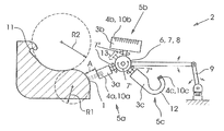
FIG. 1 thereof, there is seen a diagrammatic side view of one preferred exemplary embodiment of anapparatus 2 according to the invention forprinting surfaces 1 that are shaped in any desired manner (which are referred to in short as 3D surfaces). As shown inFIG. 1 , thesurface 1 has at least one curvature. The surface can, for example, be a vehicle body part to be painted. It is possible, by way of theapparatus 2 according to the invention, to paint surfaces which are curved or shaped in any desired manner with one color or multiple colors, or to provide them with a multiple-color information item (image, pattern or text). - The
apparatus 2 has a plurality ofmovable print heads 3 a to 3 c of different geometry which in each case include a plurality of individuallyactuable nozzles 4 a to 4 c. In the illustrated exemplary embodiment, three print heads are shown by way of example. Each of the three print heads can be moved into an (active)printing position 5 a or an (inactive)parking position printing position 5 a is a position in which theprint head 3 a is disposed within a tolerance TA at a working spacing A from thesurface 1. If so-called inkjet heads are used, the working spacing can be limited, for example, by their operating range, that is to say the substantially unimpeded range of the ink droplets. The working spacing can also be limited by a minimum spacing, for example in order to avoid collision. InFIG. 1 , theprint head 3 a is in theprinting position 5 a, whereas the twoprint heads respective parking positions - As is shown in
FIG. 1 , the three print heads 3 a-c are disposed on a common transport apparatus 6 which is configured as a rotation apparatus 7 (seearrow 7′) and moves or rotates the print heads 3 a-c into the respective positions 5 a-c. As an alternative, more than three or only two print heads can be provided. Each individual print head 3 a-c can in turn be accommodated rotatably on the rotation apparatus 7 (seearrow 7″). - A
rotation 7′ through 120° counter to the clockwise direction moves the first (active)print head 3 a out of theprinting position 5 a into theparking position 5 c and moves the second (inactive)print head 3 b out of theparking position 5 b into theprinting position 5 a (the second print head then becomes active and the first print head becomes inactive). In this case, thethird print head 3 c changes between the twoparking positions rotation apparatus 7 can have a rotatable, central carrier 8 for the number of print heads. The rotation can take place through the use of an electric motor or pneumatically. A rotation which is only back and forth can also be provided instead of a rotation through 360° or more. - The use of the rotation apparatus permits rapid and precise changes to be used between the respective print heads, in particular in conjunction with rapid control/regulation which is provided for the change of the heads and the adapted change of the image data. The respective position of the nozzles 4 a-c of the print heads 3 a-c is selected in such a way that, during a change of the active print head, no disruptive effects are produced in the printing image during the image transition, that is to say the printed image of the first print head seamlessly follows the printed image of the second print head and vice versa.
- Each individual print head 3 a-c can have nozzles 4 a-c for different colors, paints or inks, in particular for so-called CMYK printing (cyan, magenta, yellow, black). As an alternative, each individual print head 3 a-c can also be constructed from a plurality, preferably four, of partial heads each of which print only one color. The color space which can be reached by the image setting can be extended, for example by 6-color printing (CMYK, light cyan and light magenta) and by other color systems. In particular, the color space which can be reached can be extended by the additional use of white colors, paints or inks.
- It can also be provided that a hydrostatic compensation mechanism for keeping the ink printing constant in the line system of the inkjet heads (or the respective ink meniscus at the outlet openings of the nozzles) forms a unit together with the print head. That unit is accordingly moved in its entirety during the change from the printing position to the parking position.
- In a first mode, the
first print head 3 a is disposed in aprinting position 5 a and thesecond print head 3 b is disposed in aparking position 5 b. In a second mode, thefirst print head 3 a is disposed in aparking position second print head 3 b is disposed in aprinting position 5 a. As an alternative, it is also possible to move two print heads at the same time into the printing position and to switch over from one to the other print head, in order to generate image transitions without disruptive effects in this way. In this case, a third head remains in a parking position. - In the
respective parking position -
FIG. 1 also shows that the common transport apparatus 6 is disposed on a controllable and multiple-member robot arm 9. Through the use of the robot arm, the transport apparatus including the print heads 3 a-c can be positioned relative to thesurface 1 and can be guided along the latter for printing, that is to say can be moved relative to the surface. The robot arm allows any desired movements to be carried out and therefore any desired contours to be followed at the working spacing A (within the tolerance TA). A conventional robot arm or else a flexible arm (for example, a so-called bionic handling assistant which is available from the company Festo in Esslingen, Germany) can be used. As an alternative, the transport apparatus can be disposed on an X-Y-Z frame. - The print heads 3 a-c which are shown by way of example in the figure in each case include a plurality of individually actuable nozzles 4 a-c. The print heads are preferably so-called inkjet heads, preferably operating on the basis of piezoelectrically activatable nozzles. It can also be provided that, in addition to the inkjet heads 3 a-c, at least one head which produces a spray mist (that is to say, a head without a plurality of individually actuable nozzles) is provided on the transport apparatus 6, which head is used during large area, single-color painting. Furthermore, it is also possible to use so-called “continuous wave” systems, so-called “valve-jet” printing systems or so-called “bubble-jet” systems in a manner according to the invention.
- The print heads 3 a-c, which are shown by way of example in
FIG. 1 , have nozzle configurations 10 a-c which are different from one another. The nozzle configurations which are different from one another differ in terms of their respective number of nozzles. For example, the number ofnozzles 4 a of thenozzle configuration 10 a of thefirst print head 3 a is lower than the number ofnozzles 4 b of thenozzle configuration 10 b of thesecond print head 3 b. The first print head has only a few individually actuable nozzles. In contrast, the second print head has many individually actuable nozzles. The first print head is therefore preferably suitable for the (slow) printing ofsurfaces 1 with small radii of curvature R1, and the second print head is therefore preferably suitable for the (rapid) printing of surfaces with large radii of curvature R2 or flat surfaces. As shown, the surface can have both convex and concave sections. Thesmall print head 3 a is suitable, in particular, for printing concave sections with a small radius of curvature. According to the invention, depending on the topology of the surface segment to be printed, a suitable print head 3 a-c can therefore be moved into theprinting position 5 a near the segment. -
FIG. 1 also shows a section of thesurface 1 to be printed with a so-called undercut 11 which can be formed, for example, by a groove. In the case of a body part, an undercut of this type can be provided, for example, by a door handle or at outer edges which are bent over. Printing of this section can take place only by way of a verysmall print head 3 c. Thethird print head 3 c is constructed specifically for printing undercuts of this type. To this end, the third print head has a verysmall nozzle configuration 10 c. That nozzle configuration is additionally attached to abent section 12 of the print head. Thesection 12 allows the nozzle configuration to be guided into the interior of the undercut. A situation of this type is shown by way of example inFIG. 2 . - The different print heads 3 a-c can be attached to the
rotation apparatus 7 at identical spacings from one another. As an alternative to this, the different print heads can also be attached to the rotation apparatus at non-identical spacings from one another, with the result that the entire system of rotation apparatus and print heads is balanced. Likewise as an alternative, aseparate balancing weight 13 can be attached to the rotation apparatus. -
FIG. 3 shows a diagrammatic side view of a further preferred exemplary embodiment of an apparatus according to the invention for printing surfaces. Instead of the rotation apparatus which is shown inFIG. 1 , a circulatingbelt 14 is then provided, on which diverse print heads 3 a-d with different nozzle configurations 10 a-d are disposed. The belt serves to move the print heads into respective positions 5 a-d. Theprint head 3 a is situated in aprinting position 5 a, and all of theother print heads 3 b-d are situated inparking positions 5 b-d, with theprint head 3 d at the same time assuming acleaning position 5 d. In the printing position, the active print head projects, for example, out of the row of inactive print heads and in this way can be moved without problems into the working spacing A from thesurface 1. - The
belt 14 or an apparatus including the belt and its guide rollers can in turn be disposed on a robot arm 6 or an X-Y-Z frame. As an alternative to the rotation apparatus or the belt apparatus, a linear drive can also be provided for moving the print heads 3 a-d. -
FIGS. 4A to 4E show diagrammatic perspective views of preferred exemplary embodiments of apparatuses according to the invention. It can be seen inFIG. 4A that the spatial configuration of thenozzles 4 a of thenozzle configuration 10 a of theprint head 3 a is linear and has a larger number of nozzles.FIG. 4B shows asimilar print head 3 a having a smaller number ofnozzles 4 a. As a result of their hook-shaped construction, bothprint heads 3 a can be used for printing undercuts 11.FIG. 4C shows that the spatial configuration of thenozzles 4 a of thenozzle configuration 10 a can itself be hook-shaped, with the result that correspondingly shapedsurfaces 1 can be printed.FIG. 4D shows a spatial configuration of thenozzles 4 a of thenozzle configuration 10 a in which the spatial configuration is constructed to have a curved shape, in particular a circular section shape. That nozzle configuration can be used for printingconvex surfaces 1.FIG. 4E shows a spatial configuration of thenozzles 4 a of the nozzle configuration in which the spatial configuration is likewise constructed to have a curved shape, in particular a circular section shape. However, that nozzle configuration can be used for printingconcave surfaces 1. It can therefore be gathered fromFIGS. 4A to 4E that thenozzle configurations 10 a which are different from one another can differ in terms of their respective spatial configuration of thenozzles 4 a.
Claims (11)
Applications Claiming Priority (3)
| Application Number | Priority Date | Filing Date | Title |
|---|---|---|---|
| DE102011015277 | 2011-03-28 | ||
| DE102011015277 | 2011-03-28 | ||
| DE102011015277.6 | 2011-03-28 |
Publications (2)
| Publication Number | Publication Date |
|---|---|
| US20120249679A1 true US20120249679A1 (en) | 2012-10-04 |
| US8678535B2 US8678535B2 (en) | 2014-03-25 |
Family
ID=46845159
Family Applications (1)
| Application Number | Title | Priority Date | Filing Date |
|---|---|---|---|
| US13/432,235 Expired - Fee Related US8678535B2 (en) | 2011-03-28 | 2012-03-28 | Apparatus for printing surfaces having a plurality of movable print heads and system having the apparatus |
Country Status (4)
| Country | Link |
|---|---|
| US (1) | US8678535B2 (en) |
| JP (1) | JP6037636B2 (en) |
| CN (1) | CN102717606B (en) |
| DE (1) | DE102012005087A1 (en) |
Cited By (22)
| Publication number | Priority date | Publication date | Assignee | Title |
|---|---|---|---|---|
| EP3034179A1 (en) * | 2014-12-15 | 2016-06-22 | Guangzhou Lite-On Mobile Electronic Components Co. | Three-dimensional object and method of manufacturing thereof |
| WO2019109037A1 (en) * | 2017-11-30 | 2019-06-06 | Moore John R | Systems for applying coating compositions utilizing a high transfer efficiency applicator, coating layers and corresponding methods |
| WO2019182601A1 (en) * | 2018-03-22 | 2019-09-26 | Hewlett-Packard Development Company, L.P. | Moveable printheads |
| US11154892B2 (en) | 2016-12-14 | 2021-10-26 | Dürr Systems Ag | Coating device for applying coating agent in a controlled manner |
| IT202000009508A1 (en) * | 2020-04-30 | 2021-10-30 | Project42 Srl | DIGITAL PRINTER FOR THE DECORATION OF SLAB PRODUCTS |
| US11167297B2 (en) | 2016-12-14 | 2021-11-09 | Dürr Systems Ag | Print head for the application of a coating agent |
| US11167302B2 (en) | 2016-12-14 | 2021-11-09 | Dürr Systems Ag | Coating device and associated operating method |
| US11167308B2 (en) | 2016-12-14 | 2021-11-09 | Dürr Systems Ag | Print head for the application of a coating agent on a component |
| US11203030B2 (en) | 2016-12-14 | 2021-12-21 | Dürr Systems Ag | Coating method and corresponding coating device |
| US11298717B2 (en) | 2016-12-14 | 2022-04-12 | Dürr Systems Ag | Print head having a temperature-control device |
| US11338312B2 (en) | 2016-12-14 | 2022-05-24 | Dürr Systems Ag | Print head and associated operating method |
| US11440035B2 (en) | 2016-12-14 | 2022-09-13 | Dürr Systems Ag | Application device and method for applying a multicomponent coating medium |
| US11504735B2 (en) * | 2016-12-14 | 2022-11-22 | Dürr Systems Ag | Coating device having first and second printheads and corresponding coating process |
| US11524309B2 (en) * | 2017-02-01 | 2022-12-13 | Abb Schweiz Ag | Component coating |
| WO2023180832A1 (en) * | 2022-03-23 | 2023-09-28 | Ricoh Company, Ltd. | Liquid discharge system |
| CN117261452A (en) * | 2023-11-21 | 2023-12-22 | 江苏皓兮新能源技术开发有限公司 | Solar photovoltaic cell printing equipment and printing method |
| US11944990B2 (en) | 2016-12-14 | 2024-04-02 | Dürr Systems Ag | Coating device for coating components |
| US11975345B2 (en) | 2016-12-14 | 2024-05-07 | Dürr Systems Ag | Coating installation and corresponding coating method |
| US12122932B2 (en) | 2020-05-29 | 2024-10-22 | Axalta Coating Systems Ip Co., Llc | Coating compositions for application utilizing a high transfer efficiency applicator and methods and systems thereof |
| US12186763B2 (en) | 2016-12-14 | 2025-01-07 | Dürr Systems Ag | Print head with a displacing mechanism for a nozzle row |
| US12263604B2 (en) | 2021-07-30 | 2025-04-01 | Seiko Epson Corporation | Control method for robot system and robot system |
| US12539525B2 (en) | 2017-11-30 | 2026-02-03 | Axalta Coating Systems Ip Co., Llc | Coating compositions for application utilizing a high transfer efficiency applicator and methods and systems thereof |
Families Citing this family (16)
| Publication number | Priority date | Publication date | Assignee | Title |
|---|---|---|---|---|
| CN103009820A (en) * | 2013-01-14 | 2013-04-03 | 上海泰威技术发展股份有限公司 | Multidimensional jet printing device of digital jet printing machine |
| US9314970B2 (en) * | 2013-02-27 | 2016-04-19 | CEL Technology Limited | Fluid-dispensing head for a 3D printer |
| DE102013214980A1 (en) | 2013-07-31 | 2015-02-05 | Krones Ag | Printing machine with printhead control |
| US9533506B2 (en) * | 2013-09-04 | 2017-01-03 | Krones Ag | Container handling machine for printing onto container |
| DE102013016006A1 (en) * | 2013-09-26 | 2015-04-09 | Heidelberger Druckmaschinen Ag | Machine for inkjet printing of three-dimensional objects |
| US9855577B1 (en) * | 2014-01-23 | 2018-01-02 | Sio2 Medical Products, Inc. | Needle siliconization with controlled positive pressure gas flow |
| CN105856840A (en) * | 2016-03-31 | 2016-08-17 | 张义成 | High-rise outer wall cleaning and spray-painting all-in-one machine |
| DE102017207309A1 (en) * | 2016-05-31 | 2017-11-30 | Heidelberger Druckmaschinen Ag | A method of decorating a portion of an at least partially curved object surface |
| CN105965899A (en) * | 2016-07-29 | 2016-09-28 | 安庆建金智能科技有限公司 | Magnetic suspension 3D printing pen |
| US10234848B2 (en) | 2017-05-24 | 2019-03-19 | Relativity Space, Inc. | Real-time adaptive control of additive manufacturing processes using machine learning |
| CN108556488B (en) * | 2018-02-09 | 2023-10-13 | 深圳普赢创新科技股份有限公司 | Integrated multipurpose seal needle type printing head |
| CA3101061A1 (en) | 2018-06-20 | 2019-12-26 | Digital Alloys Incorporated | Multi-diameter wire feeder |
| FR3087705B1 (en) * | 2018-10-26 | 2022-02-11 | Psa Automobiles Sa | INKJET PRINTING ON A COMPLEX SURFACE |
| DE102019110564A1 (en) * | 2019-04-24 | 2020-10-29 | Dr. Ing. H.C. F. Porsche Aktiengesellschaft | Method and device for printing on a body |
| JP7666199B2 (en) * | 2021-07-30 | 2025-04-22 | セイコーエプソン株式会社 | Method for controlling robot system and robot system |
| DE102022108850A1 (en) | 2022-04-12 | 2023-10-12 | Homag Gmbh | Device for finishing a workpiece surface with a pivoting print head |
Family Cites Families (10)
| Publication number | Priority date | Publication date | Assignee | Title |
|---|---|---|---|---|
| JPS63126573A (en) * | 1986-11-15 | 1988-05-30 | Toyota Motor Corp | Method and nozzle for coating rust inhibitive sealing agent to flange mating part of steel sheets |
| DE4120293C2 (en) | 1990-07-27 | 1995-08-31 | Eastman Kodak Co | Drawing device with a mosaic ink printhead |
| EP0970811B1 (en) | 1998-07-06 | 2005-09-21 | L.A.C. Corporation | Automatic painting device |
| JP2000103041A (en) * | 1998-09-28 | 2000-04-11 | Seiko Seiki Co Ltd | Stamping device |
| JP2000238254A (en) * | 1999-02-25 | 2000-09-05 | Tenryu Ind Co Ltd | Method and machine for forming pattern on surface of article |
| US7131372B2 (en) * | 2003-12-01 | 2006-11-07 | Lockheed Martin Corporation | Miniature fluid dispensing end-effector for geometrically constrained areas |
| KR100560082B1 (en) | 2004-04-27 | 2006-03-13 | 한국과학기술원 | 3D solid color coloring method and device |
| ES2307436B1 (en) * | 2007-05-14 | 2009-10-02 | Jesus Francisco Barberan Latorre | HEAD POSITIONING SYSTEM IN PRINTERS. |
| JP2010051891A (en) * | 2008-08-28 | 2010-03-11 | Honda Motor Co Ltd | Coating robot |
| DE102008053178A1 (en) | 2008-10-24 | 2010-05-12 | Dürr Systems GmbH | Coating device and associated coating method |
-
2012
- 2012-03-13 DE DE102012005087A patent/DE102012005087A1/en active Granted
- 2012-03-23 CN CN201210148807.0A patent/CN102717606B/en active Active
- 2012-03-28 JP JP2012073885A patent/JP6037636B2/en active Active
- 2012-03-28 US US13/432,235 patent/US8678535B2/en not_active Expired - Fee Related
Cited By (48)
| Publication number | Priority date | Publication date | Assignee | Title |
|---|---|---|---|---|
| EP3034179A1 (en) * | 2014-12-15 | 2016-06-22 | Guangzhou Lite-On Mobile Electronic Components Co. | Three-dimensional object and method of manufacturing thereof |
| US10137641B2 (en) * | 2014-12-15 | 2018-11-27 | Guangzhou Lite-On Mobile Electronic Components Co. | Three-dimensional object and method of manufacturing thereof |
| US11878317B2 (en) * | 2016-12-14 | 2024-01-23 | Dürr Systems Ag | Coating device with printhead storage |
| US11504735B2 (en) * | 2016-12-14 | 2022-11-22 | Dürr Systems Ag | Coating device having first and second printheads and corresponding coating process |
| US12383921B2 (en) * | 2016-12-14 | 2025-08-12 | Dürr Systems Ag | Coating device and corresponding coating process |
| US12186763B2 (en) | 2016-12-14 | 2025-01-07 | Dürr Systems Ag | Print head with a displacing mechanism for a nozzle row |
| US11975345B2 (en) | 2016-12-14 | 2024-05-07 | Dürr Systems Ag | Coating installation and corresponding coating method |
| US11944990B2 (en) | 2016-12-14 | 2024-04-02 | Dürr Systems Ag | Coating device for coating components |
| US11813630B2 (en) | 2016-12-14 | 2023-11-14 | Dürr Systems Ag | Coating method and corresponding coating device |
| US11154892B2 (en) | 2016-12-14 | 2021-10-26 | Dürr Systems Ag | Coating device for applying coating agent in a controlled manner |
| US20240139768A1 (en) * | 2016-12-14 | 2024-05-02 | Dürr Systems Ag | Coating device and corresponding coating process |
| US11167297B2 (en) | 2016-12-14 | 2021-11-09 | Dürr Systems Ag | Print head for the application of a coating agent |
| US11167302B2 (en) | 2016-12-14 | 2021-11-09 | Dürr Systems Ag | Coating device and associated operating method |
| US11167308B2 (en) | 2016-12-14 | 2021-11-09 | Dürr Systems Ag | Print head for the application of a coating agent on a component |
| US11203030B2 (en) | 2016-12-14 | 2021-12-21 | Dürr Systems Ag | Coating method and corresponding coating device |
| US11298717B2 (en) | 2016-12-14 | 2022-04-12 | Dürr Systems Ag | Print head having a temperature-control device |
| US11338312B2 (en) | 2016-12-14 | 2022-05-24 | Dürr Systems Ag | Print head and associated operating method |
| US20230044108A1 (en) * | 2016-12-14 | 2023-02-09 | Dürr Systems Ag | Coating device and corresponding coating process |
| US11440035B2 (en) | 2016-12-14 | 2022-09-13 | Dürr Systems Ag | Application device and method for applying a multicomponent coating medium |
| US11524309B2 (en) * | 2017-02-01 | 2022-12-13 | Abb Schweiz Ag | Component coating |
| WO2019109037A1 (en) * | 2017-11-30 | 2019-06-06 | Moore John R | Systems for applying coating compositions utilizing a high transfer efficiency applicator, coating layers and corresponding methods |
| US11820910B2 (en) | 2017-11-30 | 2023-11-21 | Axalta Coating Systems Ip Co., Llc | Coating compositions for application utilizing a high transfer efficiency applicator and methods and systems thereof |
| US11453802B2 (en) | 2017-11-30 | 2022-09-27 | Axalta Coating Systems Ip Co., Llc | Method of applying a coating composition to a substrate |
| US11649372B2 (en) | 2017-11-30 | 2023-05-16 | Axalta Coating Systems Ip Co., Llc | Coating compositions for application utilizing a high transfer efficiency applicator and methods and systems thereof |
| US12539525B2 (en) | 2017-11-30 | 2026-02-03 | Axalta Coating Systems Ip Co., Llc | Coating compositions for application utilizing a high transfer efficiency applicator and methods and systems thereof |
| GB2582112A (en) * | 2017-11-30 | 2020-09-09 | Axalta Coating Systems Gmbh | Systems for applying coating compositions utilizing a high transfer efficiency applicator, coating layers and corresponding methods |
| US12054634B2 (en) | 2017-11-30 | 2024-08-06 | Axalta Coating Systems Ip Co., Llc | Method of applying a coating composition to a substrate |
| US11649371B2 (en) | 2017-11-30 | 2023-05-16 | Axalta Coating Systems Ip Co., Llc | Method of forming a coating composition for application to a substrate utilizing a high transfer efficiency applicator |
| US11649373B2 (en) | 2017-11-30 | 2023-05-16 | Axalta Coating Systems Ip Co., Llc | Coating compositions for application utilizing a high transfer efficiency applicator and methods and systems thereof |
| US11655391B2 (en) | 2017-11-30 | 2023-05-23 | Axalta Coating Systems Ip Co., Llc | Coating compositions for application utilizing a high transfer efficiency applicator and methods and systems thereof |
| US11649374B2 (en) | 2017-11-30 | 2023-05-16 | Axalta Coating Systems Ip Co., Llc | Coating compositions for application utilizing a high transfer efficiency applicator and methods and systems thereof |
| US11965107B2 (en) | 2017-11-30 | 2024-04-23 | Axalta Coating Systems Ip Co., Llc | System for applying a coating composition |
| US11945964B2 (en) | 2017-11-30 | 2024-04-02 | Axalta Coating Systems Ip Co., Llc | Coating compositions for application utilizing a high transfer efficiency applicator and methods and systems thereof |
| GB2582112B (en) * | 2017-11-30 | 2022-10-19 | Axalta Coating Systems Gmbh | Coating compositions for application utilizing a high transfer efficiency applicator and methods and systems thereof |
| US11840639B2 (en) | 2017-11-30 | 2023-12-12 | Axalta Coating Systems Ip Co., Llc | Coating compositions for application utilizing a high transfer efficiency applicator and methods and systems thereof |
| US11613669B2 (en) | 2017-11-30 | 2023-03-28 | Axalta Coating Systems Ip Co., Llc | Coating compositions for application utilizing a high transfer efficiency applicator and methods and systems thereof |
| JP2021514871A (en) * | 2018-03-22 | 2021-06-17 | ヒューレット−パッカード デベロップメント カンパニー エル.ピー.Hewlett‐Packard Development Company, L.P. | Movable print head |
| EP3746306A4 (en) * | 2018-03-22 | 2021-09-22 | Hewlett-Packard Development Company, L.P. | MOBILE PRINTHEADS |
| US11752788B2 (en) | 2018-03-22 | 2023-09-12 | Hewlett-Packard Development Company, L.P. | Moveable printheads |
| CN111886138A (en) * | 2018-03-22 | 2020-11-03 | 惠普发展公司,有限责任合伙企业 | Movable printing head |
| KR20200122352A (en) * | 2018-03-22 | 2020-10-27 | 휴렛-팩커드 디벨롭먼트 컴퍼니, 엘.피. | Removable printhead |
| KR102438297B1 (en) | 2018-03-22 | 2022-08-30 | 휴렛-팩커드 디벨롭먼트 컴퍼니, 엘.피. | movable printhead |
| WO2019182601A1 (en) * | 2018-03-22 | 2019-09-26 | Hewlett-Packard Development Company, L.P. | Moveable printheads |
| IT202000009508A1 (en) * | 2020-04-30 | 2021-10-30 | Project42 Srl | DIGITAL PRINTER FOR THE DECORATION OF SLAB PRODUCTS |
| US12122932B2 (en) | 2020-05-29 | 2024-10-22 | Axalta Coating Systems Ip Co., Llc | Coating compositions for application utilizing a high transfer efficiency applicator and methods and systems thereof |
| US12263604B2 (en) | 2021-07-30 | 2025-04-01 | Seiko Epson Corporation | Control method for robot system and robot system |
| WO2023180832A1 (en) * | 2022-03-23 | 2023-09-28 | Ricoh Company, Ltd. | Liquid discharge system |
| CN117261452A (en) * | 2023-11-21 | 2023-12-22 | 江苏皓兮新能源技术开发有限公司 | Solar photovoltaic cell printing equipment and printing method |
Also Published As
| Publication number | Publication date |
|---|---|
| JP6037636B2 (en) | 2016-12-07 |
| DE102012005087A1 (en) | 2012-10-04 |
| CN102717606B (en) | 2016-02-17 |
| US8678535B2 (en) | 2014-03-25 |
| JP2012206116A (en) | 2012-10-25 |
| CN102717606A (en) | 2012-10-10 |
Similar Documents
| Publication | Publication Date | Title |
|---|---|---|
| US8678535B2 (en) | Apparatus for printing surfaces having a plurality of movable print heads and system having the apparatus | |
| US10821725B2 (en) | Device for imaging and/or varnishing the surfaces of objects | |
| CN112492879B (en) | Device for printing or coating the surface of a three-dimensional part | |
| CA2686961C (en) | Device for printing a component by means of a digital printing method | |
| US9108442B2 (en) | Image forming apparatus | |
| US8172391B2 (en) | Image forming apparatus | |
| EP2055490B1 (en) | Printing arrangement and method of depositing a substance | |
| JP4963869B2 (en) | Apparatus and method for patterning short side portion of plate-like workpiece | |
| CN101259800A (en) | 3D printer | |
| JP2016123942A (en) | Ink jet printing method and ink jet coater | |
| CN113939404B (en) | Ink-jet printer and one-pass ink-jet printing method thereof | |
| US9718291B2 (en) | Printer carriage support structure | |
| US9434161B2 (en) | Print head unit | |
| CN113905889B (en) | Ink-jet printer and one-pass ink-jet printing method | |
| JP5304516B2 (en) | Fluid ejecting apparatus and fluid ejecting method | |
| JP7413510B2 (en) | Conveyance device, printing device and conveyance method | |
| CN100569517C (en) | Inkjet recording equipment | |
| CN102991139A (en) | Print head, inkjet printer and printing method | |
| JP2009012349A (en) | Liquid ejection apparatus and liquid ejection method | |
| US20250319699A1 (en) | Liquid ejecting apparatus | |
| JP7803911B2 (en) | Inkjet recording apparatus and inkjet recording method | |
| JP7424062B2 (en) | Device that discharges liquid | |
| NL2022709B1 (en) | A liquid handling system for a printer | |
| JP4502000B2 (en) | Droplet discharge device | |
| US12157316B2 (en) | Nozzle surface recovery device, liquid discharge device, and inkjet printer |
Legal Events
| Date | Code | Title | Description |
|---|---|---|---|
| AS | Assignment |
Owner name: HEIDELBERGER DRUCKMASCHINEN AKTIENGESELLSCHAFT, GE Free format text: ASSIGNMENT OF ASSIGNORS INTEREST;ASSIGNORS:BEIER, BERNARD;PITZ, HEINER;REEL/FRAME:028086/0321 Effective date: 20120404 |
|
| STCF | Information on status: patent grant |
Free format text: PATENTED CASE |
|
| FPAY | Fee payment |
Year of fee payment: 4 |
|
| FEPP | Fee payment procedure |
Free format text: MAINTENANCE FEE REMINDER MAILED (ORIGINAL EVENT CODE: REM.); ENTITY STATUS OF PATENT OWNER: LARGE ENTITY |
|
| LAPS | Lapse for failure to pay maintenance fees |
Free format text: PATENT EXPIRED FOR FAILURE TO PAY MAINTENANCE FEES (ORIGINAL EVENT CODE: EXP.); ENTITY STATUS OF PATENT OWNER: LARGE ENTITY |
|
| STCH | Information on status: patent discontinuation |
Free format text: PATENT EXPIRED DUE TO NONPAYMENT OF MAINTENANCE FEES UNDER 37 CFR 1.362 |
|
| FP | Lapsed due to failure to pay maintenance fee |
Effective date: 20220325 |