US20120249653A1 - Filter manufacturing apparatus and filter manufacturing method - Google Patents
Filter manufacturing apparatus and filter manufacturing method Download PDFInfo
- Publication number
- US20120249653A1 US20120249653A1 US13/437,603 US201213437603A US2012249653A1 US 20120249653 A1 US20120249653 A1 US 20120249653A1 US 201213437603 A US201213437603 A US 201213437603A US 2012249653 A1 US2012249653 A1 US 2012249653A1
- Authority
- US
- United States
- Prior art keywords
- printing
- cells
- pattern
- printing pattern
- complementary
- Prior art date
- Legal status (The legal status is an assumption and is not a legal conclusion. Google has not performed a legal analysis and makes no representation as to the accuracy of the status listed.)
- Granted
Links
- 238000004519 manufacturing process Methods 0.000 title claims abstract description 50
- 238000007639 printing Methods 0.000 claims abstract description 383
- 230000000295 complement effect Effects 0.000 claims description 93
- 239000000463 material Substances 0.000 claims description 28
- 238000000034 method Methods 0.000 claims description 20
- 238000007641 inkjet printing Methods 0.000 claims description 13
- 239000000976 ink Substances 0.000 description 39
- 238000010276 construction Methods 0.000 description 9
- 230000001788 irregular Effects 0.000 description 6
- 230000007723 transport mechanism Effects 0.000 description 5
- 238000007599 discharging Methods 0.000 description 4
- 238000000206 photolithography Methods 0.000 description 3
- 238000010586 diagram Methods 0.000 description 2
- 239000004973 liquid crystal related substance Substances 0.000 description 2
- 230000007246 mechanism Effects 0.000 description 2
- 239000002904 solvent Substances 0.000 description 2
- 239000003795 chemical substances by application Substances 0.000 description 1
- 238000004140 cleaning Methods 0.000 description 1
- 239000011248 coating agent Substances 0.000 description 1
- 239000011521 glass Substances 0.000 description 1
- 239000013307 optical fiber Substances 0.000 description 1
- 239000000126 substance Substances 0.000 description 1
- 239000000758 substrate Substances 0.000 description 1
Images


Classifications
-
- B—PERFORMING OPERATIONS; TRANSPORTING
- B41—PRINTING; LINING MACHINES; TYPEWRITERS; STAMPS
- B41J—TYPEWRITERS; SELECTIVE PRINTING MECHANISMS, i.e. MECHANISMS PRINTING OTHERWISE THAN FROM A FORME; CORRECTION OF TYPOGRAPHICAL ERRORS
- B41J3/00—Typewriters or selective printing or marking mechanisms characterised by the purpose for which they are constructed
- B41J3/407—Typewriters or selective printing or marking mechanisms characterised by the purpose for which they are constructed for marking on special material
-
- B—PERFORMING OPERATIONS; TRANSPORTING
- B41—PRINTING; LINING MACHINES; TYPEWRITERS; STAMPS
- B41J—TYPEWRITERS; SELECTIVE PRINTING MECHANISMS, i.e. MECHANISMS PRINTING OTHERWISE THAN FROM A FORME; CORRECTION OF TYPOGRAPHICAL ERRORS
- B41J2/00—Typewriters or selective printing mechanisms characterised by the printing or marking process for which they are designed
- B41J2/005—Typewriters or selective printing mechanisms characterised by the printing or marking process for which they are designed characterised by bringing liquid or particles selectively into contact with a printing material
- B41J2/01—Ink jet
- B41J2/015—Ink jet characterised by the jet generation process
- B41J2/04—Ink jet characterised by the jet generation process generating single droplets or particles on demand
- B41J2/045—Ink jet characterised by the jet generation process generating single droplets or particles on demand by pressure, e.g. electromechanical transducers
- B41J2/04501—Control methods or devices therefor, e.g. driver circuits, control circuits
- B41J2/04505—Control methods or devices therefor, e.g. driver circuits, control circuits aiming at correcting alignment
-
- B—PERFORMING OPERATIONS; TRANSPORTING
- B41—PRINTING; LINING MACHINES; TYPEWRITERS; STAMPS
- B41J—TYPEWRITERS; SELECTIVE PRINTING MECHANISMS, i.e. MECHANISMS PRINTING OTHERWISE THAN FROM A FORME; CORRECTION OF TYPOGRAPHICAL ERRORS
- B41J2/00—Typewriters or selective printing mechanisms characterised by the printing or marking process for which they are designed
- B41J2/005—Typewriters or selective printing mechanisms characterised by the printing or marking process for which they are designed characterised by bringing liquid or particles selectively into contact with a printing material
- B41J2/01—Ink jet
- B41J2/015—Ink jet characterised by the jet generation process
- B41J2/04—Ink jet characterised by the jet generation process generating single droplets or particles on demand
- B41J2/045—Ink jet characterised by the jet generation process generating single droplets or particles on demand by pressure, e.g. electromechanical transducers
- B41J2/04501—Control methods or devices therefor, e.g. driver circuits, control circuits
- B41J2/04573—Timing; Delays
-
- B—PERFORMING OPERATIONS; TRANSPORTING
- B41—PRINTING; LINING MACHINES; TYPEWRITERS; STAMPS
- B41J—TYPEWRITERS; SELECTIVE PRINTING MECHANISMS, i.e. MECHANISMS PRINTING OTHERWISE THAN FROM A FORME; CORRECTION OF TYPOGRAPHICAL ERRORS
- B41J2/00—Typewriters or selective printing mechanisms characterised by the printing or marking process for which they are designed
- B41J2/005—Typewriters or selective printing mechanisms characterised by the printing or marking process for which they are designed characterised by bringing liquid or particles selectively into contact with a printing material
- B41J2/01—Ink jet
- B41J2/015—Ink jet characterised by the jet generation process
- B41J2/04—Ink jet characterised by the jet generation process generating single droplets or particles on demand
- B41J2/045—Ink jet characterised by the jet generation process generating single droplets or particles on demand by pressure, e.g. electromechanical transducers
- B41J2/04501—Control methods or devices therefor, e.g. driver circuits, control circuits
- B41J2/04586—Control methods or devices therefor, e.g. driver circuits, control circuits controlling heads of a type not covered by groups B41J2/04575 - B41J2/04585, or of an undefined type
Definitions
- This invention relates to a filter manufacturing apparatus and a filter manufacturing method, and more particularly to a technique of manufacturing color filters by inkjet printing for use in liquid crystal displays or electronic paper.
- Patent Document 1 Japanese Unexamined Patent Publication H9-138306 discloses an apparatus for manufacturing color filters using an inkjet apparatus of the one-pass type.
- the nozzle pitch of the inkjet head is standardized in the industry, and the arrangement pitch of filters does not usually agree with the nozzle pitch.
- the inkjet head is inclined to match the cosine component of the nozzle pitch with the arrangement pitch of filters. In this case, it is necessary to adjust printing timing of each nozzle individually, which makes control complicated. An angle of inclination of the inkjet head must be changed whenever the filter pitch of a printing medium is changed, which requires a time-consuming adjustment.
- This invention has been made having regard to the state of the art noted above, and its object is to provide a filter manufacturing apparatus and a filter manufacturing method for manufacturing filters without inclining an inkjet head.
- a filter manufacturing apparatus for manufacturing, by inkjet printing, filters arranged at intervals in a transport direction of a printing medium and in a direction perpendicular to the transport direction, the apparatus comprising a printing cell setting unit for setting, based on a predetermined filter pitch and a head resolution, printing cells having an equal number of dot areas in the direction perpendicular to the transport direction of the printing medium; a shift amount calculating unit for calculating shift amounts between the filter pitch and the printing cells in the direction perpendicular to the transport direction of the printing medium; a shift amount determining unit for determining whether shift amounts of the printing cells exceed a unit dot area; and a printing cell complementing unit for complementing the shift amounts of the printing cells exceeding the unit dot area by adjusting the number of dot areas included in the printing cells.
- printing cells having an equal number of dot areas in the direction perpendicular to the transport direction of the printing material are set based on a filter pitch and a head resolution. Shift amounts between the filter pitch and the printing cells, and whether shift amounts of the printing cells exceed a unit dot area is determined. For the printing cells including shift amounts exceeding the unit dots area, the shift amounts are complemented by adjusting the number of dot areas included in the printing cells. Consequently, even if the filter pitch and head resolution are not in agreement, shifts of the filter pitch can be made smaller than the head resolution. Filters can be manufactured with high filter pitch accuracy by inkjet printing without inclining inkjet heads.
- a preferred example of the filter manufacturing apparatus further comprises a complementary printing pattern creating unit for creating a complementary printing pattern corresponding to the printing cells complemented by the printing cell complementing unit from a predetermined printing pattern to be ejected in the printing cells; and a printing pattern setting unit for allocating the printing pattern to the printing cells and allocating the complementary printing pattern to the complemented printing cells.
- the complementary printing pattern creating unit is arranged to create the complementary printing pattern by reducing non-ejection dot areas in the printing pattern.
- the complementary printing pattern is an asymmetrical pattern.
- This construction employs an asymmetrical pattern as the complementary printing pattern. Since it has an irregular printing pattern in the arrangement of filters, pitch unevenness can be reduced.
- the complementary printing pattern creating unit is arranged to create plural types of complementary printing pattern; and the printing pattern setting unit is arranged to allocate at random the plural types of complementary printing pattern to the complemented printing cells.
- plural types of printing pattern are printed at random as complementary printing patterns. With irregular printing patterns in the arrangement of filters, pitch unevenness can be reduced.
- the printing pattern has ejection dot areas on diagonal lines in the printing cells.
- the printing pattern has ejection dot areas on diagonal lines in the printing cells, which enables ejected ink to be efficiently diffused within the printing cells.
- a second aspect of this invention provides a filter manufacturing method for manufacturing, by inkjet printing, filters arranged at intervals in a transport direction of a printing medium and in a direction perpendicular to the transport direction, the method comprising a printing cell setting step for setting, based on a predetermined filter pitch and a head resolution, printing cells having an equal number of dot areas in the direction perpendicular to the transport direction of the printing medium; a shift amount calculating step for calculating shift amounts between the filter pitch and the printing cells in the direction perpendicular to the transport direction of the printing medium; a shift amount determining step for determining whether shift amounts of printing cells exceed a unit dot area; and a printing cell complementing step for complementing the shift amounts of the printing cells exceeding the unit dot area by adjusting the number of dot areas included in the printing cells.
- printing cells having an equal number of dot areas in the direction perpendicular to the transport direction of the printing medium are set based on a filter pitch and a head resolution. Shift amounts between the filter pitch and the printing cells, and whether shift amounts of the printing cells exceed a unit dot area is determined. For the printing cells including shift amounts exceeding the unit dots area, the shift amounts are complemented by adjusting the number of dot areas included in the printing cells. Consequently, even if the filter pitch and head resolution are not in agreement, shifts of the filter pitch can be made smaller than the head resolution.
- Filters can be manufactured with high filter pitch accuracy by inkjet printing without inclining inkjet heads. Since the inkjet heads are not inclined, the method can be used effectively where nozzle openings are arranged in a plurality of rows.
- a preferred example of the filter manufacturing method further comprises a complementary printing pattern creating step for creating a complementary printing pattern corresponding to the printing cells complemented by the printing cell complementing step with a predetermined printing pattern to be ejected in the printing cells; and a printing pattern setting step for allocating the printing pattern to the printing cells and allocating the complementary printing pattern to the complemented printing cells.
- the printing pattern creating step creates the complementary printing pattern corresponding to the complemented printing cells, adjustment can be made to a proper ink quantity to be discharged to proper discharge positions, thereby to print filters appropriately according to the size of the printing cells.
- the complementary printing pattern creating step is executed to create the complementary printing pattern by reducing non-ejection dot areas in the printing pattern.
- the complementary printing pattern is an asymmetrical pattern.
- This method employs an asymmetrical pattern as the complementary printing pattern. Since it has an irregular printing pattern in the arrangement of filters, pitch unevenness can be reduced.
- the complementary printing pattern creating step is executed to create plural types of complementary printing pattern; and the printing pattern setting step is executed to allocate at random the plural types of complementary printing pattern to the complemented printing cells.
- plural types of printing pattern are printed at random as complementary printing patterns. With irregular printing patterns in the arrangement of filters, pitch unevenness can be reduced.
- the printing pattern has ejection dot areas on diagonal lines in the printing cells.
- the printing pattern has ejection dot areas on diagonal lines in the printing cells, which enables ejected ink to be efficiently diffused within the printing cells.
- Filters can be manufactured with high filter pitch accuracy by inkjet printing without inclining inkjet heads.
- FIG. 1 is an overall perspective view of a filter manufacturing apparatus according to this invention
- FIG. 2 is a bottom plan view of a discharger
- FIG. 3 is a block diagram showing a construction of an image data creator
- FIG. 4 is an explanatory view showing an arrangement of color filters
- FIG. 5 is an explanatory view showing an arrangement of printing cells relative to a filter pitch
- FIG. 6 is an explanatory view showing an arrangement of printing cells relative to the filter pitch
- FIG. 7 is an explanatory view illustrating a printing pattern
- FIG. 8 is an explanatory view illustrating a complementary printing pattern
- FIG. 9 is an explanatory view illustrating a complementary printing pattern
- FIG. 10 is an explanatory view illustrating an arrangement of a printing pattern and a complementary printing pattern allocated to the printing cells
- FIG. 11 is a flow chart showing a sequence of manufacturing filters
- FIG. 12 is an explanatory view illustrating a modified printing pattern
- FIG. 13 is an explanatory view illustrating a modified complementary printing pattern
- FIG. 14 is an explanatory view illustrating a modified complementary printing pattern.
- FIG. 1 is an overall outline view of a filter manufacturing apparatus.
- a filter manufacturing apparatus 1 manufactures color filters on a base material 91 by inkjet printing.
- This embodiment employs and describes an inkjet printing machine of the multipass type.
- the base material 91 may be a glass substrate, or may be paper with a coating agent applied thereto.
- the base material 91 corresponds to the printing medium in this invention.
- the filter manufacturing apparatus 1 includes a transport mechanism 2 for transporting the base material 91 , a print head 3 for ejecting UV curable inks onto the base material 91 being transported, a controller 4 for controlling transport timing of the base material 91 and ink ejection timing of the print head 3 , and an image data creator 5 for creating image data corresponding to areas to which inks are ejected, and an input unit 6 for inputting various condition settings.
- the transport mechanism 2 has a stage 11 for holding the base material 91 , a base block 12 on which the stage 11 is placed, a position detector 13 mounted on the base block 12 for detecting positions of the stage 11 relative to the base block 12 , and a stage drive 14 for moving the stage 11 forward or backward in a transport direction.
- the print head 3 has a discharger 21 for discharging the inks, and a discharger transport mechanism 23 for moving the discharger 21 in directions perpendicular to the transport direction of the base material 91 .
- FIG. 2 is a bottom plan view of the discharger 21 .
- the discharger 21 has a plurality of head units 24 for discharging inks of different color components.
- the head units 24 are fixed to a body 25 of the discharger 21 in an arrangement in a (+Y) direction which is a reverse transport direction of the base material 91 .
- the head units 24 discharge R (red), G (green) and B (blue) inks.
- Each ink includes an ultraviolet curing agent to be UV curable.
- Each head unit 24 has a plurality of heads 26 of the piezo drive type, for example, arranged zigzag in X-direction (hereinafter called the “width direction”) perpendicular to the transport direction of the base material 91 .
- Each head 26 has a plurality of nozzles 27 arranged in the width direction on a lower surface thereof for discharging minute ink droplets. The nozzles 27 are depicted only on some heads 26 . Consequently, each head unit 24 as a whole has a plurality of nozzles 27 arranged at a constant pitch in the width direction, to be able to form a plurality of dots aligned in the width direction on the base material 91 , in each position in a scan direction of the discharger 21 .
- the discharger 21 may be provided with one head unit 24 for each color.
- the discharger 21 includes an emission unit 28 disposed on the (+Y) side of the plurality of the head units 24 and connected to a light source which generates ultraviolet light.
- the light source is provided rearward of the discharger 21 .
- the emission unit 28 has a plurality of optical fibers arranged in X-direction. Thus, the emission unit 28 emits ultraviolet light to linear areas extending in X-direction on the base material 91 .
- the UV curable inks are discharged while the base material 91 is transported in ( ⁇ Y) direction relative to the discharger 21 , and the inks are cured immediately after discharge on the base material 91 by the ultraviolet light emitted from the emission unit 28 to the inks.
- the light source 22 and the emission unit 28 act as a curing device for curing the inks.
- the discharger 21 moves in X-direction. That is, the transport mechanism 2 and discharger moving mechanism 23 act as mechanisms for moving the discharger 21 relative to the base material 91 in parallel with the discharge of the inks from the discharger 21 .
- Printing is carried out in an interlace mode. After a color ink is once discharged to a position, the ink may be repeatedly discharged to the same position to improve printing density of the color ink.
- a one-pass mode may be employed, in which the nozzles 27 are arranged at a sufficiently small pitch, and printing is completed with the base material 91 moved once in ( ⁇ Y) direction relative to the discharger 21 .
- printing may be carried out by reciprocating the base material 91 in ( ⁇ Y) direction and (+Y) direction while discharging ink droplets. While UV curable inks are employed in this embodiment, solvent inks may be employed instead. When employing solvent inks, the inks are dried naturally or by using a heater or heaters.
- FIG. 3 is a block diagram showing a construction of the image data creator
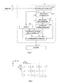
- FIG. 4 is an explanatory view showing an arrangement of color filters manufactured.
- R represents red filters, G green filters and B blue filters.
- Each of the R, G and B filters is square.
- the R, G and B filters may be rectangle, instead of being square.
- the filters are arranged at a filter pitch Fpx in the width direction, and at a filter pitch Fpy in the transport direction.
- the arrangement of the color filters is not limited to what is shown, but may be otherwise.
- the image data creator 5 creates image data for the color filters based on the arrangement pitch of the color filters and the pitch of the nozzles 27 .
- the image data creator 5 includes a printing cell setting unit 35 for setting printing cells having an equal number of dot areas in the direction (X-direction) perpendicular to the transport direction of the base material 91 based on a filter pitch and a head resolution inputted to the input unit 6 , a shift amount calculating unit 36 for calculating shift amounts between the filter pitch and printing cells in the direction perpendicular to the transport direction of the base material 91 , a shift amount determining unit 37 for determining whether shift amounts of the printing cells exceed a unit dot area or not, a printing cell complementing unit 38 for complementing the shift amounts of the printing cells exceeding the unit dot area by adjusting the number of dot areas included in the printing cells.
- the image data creator 5 further includes a memory unit 39 storing a predetermined printing pattern to be ejected in the printing cells, a complementary printing pattern creating unit 40 for creating complementary printing patterns corresponding to the printing cells complemented by the printing cell complementing unit 38 from the predetermined printing pattern to be ejected to the printing cells, a printing pattern setting unit 41 for allocating the printing pattern to the printing cells and allocating the complementary printing patterns to the complemented printing cells.
- the image data creator 5 is constructed of a microprocessor and memory, but may be part of the CPU of the controller 4 .
- the printing cell setting unit 35 virtually sets printing cells Pc based on the filter pitch Fpx in X-direction and the filter pitch Fpy in Y-direction. Particularly in X-direction perpendicular to the transport direction of the base material 91 , printing cells Pc are set, based on the filter pitch Fpx and the head resolution of the head units 24 , to have an equal number of dot areas.
- the filter pitch Fpx and filter pitch Fpy have predetermined values inputted to the input unit 6 by the operator.
- the head resolution means a minimum printing pitch Pm in the width direction, which in this embodiment is 2400 dpi.
- nozzle pitch Np is 300 dpi, for example, 2400 dpi can be printed by scanning eight times in the width direction in the multipass mode. In the case of the one-pass mode, it can be attained by providing eight head units of the same color and shifting the head units in the width direction.
- the minimum printing pitch Pm in this embodiment is 10.58 ⁇ m. Areas formed at the minimum printing pitch Pm are considered the dot areas. In this embodiment, areas of 10.58 ⁇ m square are made the dot areas.
- FIGS. 5 and 6 are explanatory views showing an arrangement of printing cells relative to the filter pitch.
- Width Pcx in X-direction of the printing cells Pc has a value obtained by dividing the filter pitch Fpx by the minimum printing pitch Pm, rounding up a decimal fraction of the quotient, and multiplying the result by the minimum printing pitch Pm.
- Fpx/Pm 10.39 ⁇ 11. That is, 11 dot areas are included in X-direction in each printing cell Pc corresponding to filter pitch Fpx.
- width Pcx in X-direction width Pcy in Y-direction of the printing cells Pc has a value obtained by dividing the filter pitch Fpy by the minimum printing pitch Pm, rounding up a decimal fraction of the quotient, and multiplying the result by the minimum printing pitch Pm.
- a shift between the filter pitch Fpy and printing cell width Pcy in Y-direction can be complemented by the controller 4 adjusting transport timing of the base material 91 and ejection timing of the inks.
- the shift amount calculating unit 36 calculates shift amounts Gd n between the filter pitch Fpx and printing cells Pc in X-direction.
- the shift amounts Gd n are calculated from the following equation:
- Gd n ( Pcx ⁇ Fpx )+ Gd n ⁇ 1 (1)
- n is a natural number representing the number of printing cells Pc from the origin of X-direction.
- the shift amount determining unit 37 determines whether a shift amount Gd n between the filter pitch Fp and an allocated printing cell Pc exceeds the unit dot area. When the shift amount Gd n is found to exceed the unit dot area, i.e. 10.58 ⁇ m, a complementing signal is sent to the printing cell complementing unit 38 and shift amount calculating unit 36 . In this embodiment, since Gd 3 >10.58 ⁇ m, the complementing signal is outputted for Gd 3 .
- the printing cell complementing unit 38 Upon receipt of the complementing signal, the printing cell complementing unit 38 complements the shift amount Gd n of the printing cell Pc exceeding the unit dot area by adjusting the number of dot areas included in the printing cell Pc. That is, since the printing cell Pc is formed of 11 dot areas in X-direction, the number of dot areas is reduced by one, thereby forming a printing cell Pc of ten dot areas in X-direction, which makes a shift amount smaller than the unit dot area. Consequently, printing cell Pc 3 is formed of ten dot areas in X-direction (see FIG. 6 ).
- Pc n (n being a natural number) represents printing cells Pc counted in order from the origin of X-direction.
- the shift amount calculating unit 36 Upon receipt of the complementing signal, the shift amount calculating unit 36 calculates a complementary shift amount Gd′ which complements the width of the unit dot area from the calculated shift amount Gd.
- shift amount Gd 4 can be calculated from equation (1) next.
- a gray scale head is used in this embodiment, which enables the quantity of ink discharged at a time from the nozzles 27 to be adjusted to a plurality of stages. That is, one nozzle 27 located over one dot area Da can apply an ink quantity diffusing to a plurality of dot areas Da.
- plural types of printing pattern Pp as shown in FIG. 7 , for example, corresponding to the sizes of printing cells Pc are stored beforehand in the memory unit 39 .
- FIG. 7 is a view showing a printing pattern for the printing cells Pc formed of 11 dots ⁇ 11 dots. The ink ejected centering on ejection areas 45 spreads to application areas 46 and application areas 47 .
- the complementary printing pattern creating unit 40 reads a printing pattern Pp stored in the memory unit 39 and corresponding to the size of printing cells Pc, and creates a complementary printing pattern Pp′ corresponding to complemented printing cells Pc′. It is desirable to create plural types of complementary printing pattern Pp′. As shown in FIGS. 8 and 9 , the complementary printing patterns Pp′ are created by reducing non-ejection dot areas from the printing pattern Pp, and the ejection dot areas are arranged asymmetrically in the complementary printing patterns. The complementary printing patterns Pp′ shown in FIGS. 8 and 9 are created based on the printing pattern Pp shown in FIG. 7 . The created complementary printing patterns Pp′ are sent to the printing pattern setting unit 41 . As a result of complementary printing, as shown in FIGS. 8 and 9 , the ink will spread evenly.
- the printing pattern setting unit 41 allocates the printing pattern Pp and complementary printing pattern Pp′ to the set printing cells Pc and complemented printing cells Pc′, respectively.
- the printing pattern setting unit 41 selects and allocates at random one of the complementary printing patterns Pp′ to the complemented printing cell Pc′ (see FIG. 10 ). Since each printing pattern is set to the printing cells in the first row in Y-direction, the same printing pattern as set to the first row may be set to the second and subsequent rows. Image data created by setting each printing pattern to the printing cells is sent to the controller 4 .
- FIG. 11 is a flow chart showing a sequence of manufacturing filters.
- the operator inputs pitch Fpx in X-direction and pitch Fpy in Y-direction of the filters to be manufactured. Further, the operator inputs a head resolution.
- the inputted data is sent to the image data creator 5 through the controller 4 .
- the printing cell setting unit 35 in the image data creator 5 based on the pitch Fpx in X-direction and the head resolution sent from the input unit 6 , sets printing cells Pc having an equal number of dot areas Da in the direction (X-direction) perpendicular to the transport direction of the base material 91 , and sets printing cells Pcn from the origin of X-direction (step S 1 ).
- the shift amount calculating unit 36 calculates shift amounts Gd n between the filter pitch Fpx and printing cells Pc in X-direction (step S 2 ).
- the shift amount determining unit 37 determines whether the shift amount Gd n between the filter pitch Fp and allocated printing cell Pcn exceeds the unit dot area (step S 3 ). When the shift amount Gd n is found not to exceed the unit dot area, the printing pattern setting unit 41 allocates the printing pattern Pp stored beforehand in the memory unit 39 to the set printing cells Pc (step S 7 ).
- a complementing signal is sent to the printing cell complementing unit 38 and shift amount calculating unit 36 .
- the printing cell complementing unit 38 complements the shift amount of the printing cell Pc n exceeding the unit dot area by adjusting the number of dot areas included in the printing cell Pc n (step S 4 ). For example, the number of dot areas in X-direction in the printing cell Pc n is reduced by one, thereby making the shift amount smaller than the unit dot area.
- the complementary printing pattern creating unit 40 reads the printing pattern Pp stored in the memory unit 39 and corresponding to the size of printing cells Pc, and creates complementary printing patterns Pp′ corresponding to complemented printing cells Pc′ (step S 5 ).
- Plural types of complementary printing pattern Pp′ are created.
- the complementary printing patterns Pp′ are created by reducing non-ejection dot areas in the printing pattern Pp, and the ejection dot areas are arranged asymmetrically in the complementary printing patterns.
- the complementary printing patterns Pp′ may be created only once, and their subsequent creation may be omitted.
- the shift amount calculating unit 36 Upon receipt of the complementing signal, the shift amount calculating unit 36 calculates a complementary shift amount Gd n ′ which complements the width of the unit dot area from the calculated shift amount, and uses it as new shift amount Gd n when calculating shift amount Gd n+1 (step S 6 ).
- the printing pattern setting unit 41 allocates a complementary printing pattern Pp′ to complemented printing cell Pc′ (step S 7 ).
- the complement printing patterns Pp′ may be allocated by turns or one pattern may be selected at random and allocated to the complemented printing cell Pc′.
- step S 8 it is checked whether all printing cells have been set. When all printing cells have not been set, the operation returns to step S 1 , to set printing cell Pc n+1 in (+X) direction next to the printing cell Pcn, and set a printing pattern to the printing cell Pc n+1 .
- the creation of image data is ended, and the created image data is sent to the controller 4 .
- the controller 4 controls ejection timing of the inks and transport timing of the base material 91 for the print head 3 and transport mechanism 2 , and manufactures the filters. Only the printing method in the direction (direction of the nozzle rows) perpendicular to the transport direction of the base material 91 has been described in this embodiment. As for the filter pitch in the transport direction of the base material 91 , printing at a set pitch can be achieved by adjusting the transport speed of the printing medium according to the driving frequency of the head.
- filters can be manufactured by inkjet printing without inclining the inkjet head units 24 . Shifts of the filter pitch Fpx can be made smaller than the head resolution, which enables the filters to be manufactured while keeping the filter pitch highly accurate. Further, by setting the printing pattern Pp to the set printing cells, when a gray scale head is used, a proper ink quantity can be ejected to proper discharge positions, thereby to reduce the number of times of ejection.
- the complementary printing pattern creating unit 40 creating the complementary printing pattern Pp′ corresponding to the complemented printing cell Pc′, adjustment can be made to a proper ink quantity to be ejected to proper discharge positions, thereby to print filters appropriately according to the size of the printing cells.
- the complementary printing pattern Pp is created by reducing the non-ejection dot areas in the printing pattern, density variations of a filter color between printing pattern Pp not complemented and printing pattern Pp′ complemented can be inhibited. Further, a pattern with asymmetrical ejection areas is employed as the complementary printing pattern Pp′. Since it has an irregular printing pattern in the arrangement of filters, pitch unevenness can be reduced. With plural types of printing pattern printed at random as complementary printing patterns Pp′, since they have generally irregular printing patterns in the arrangement of filters, pitch unevenness can be reduced.
- the printing pattern Pp has ejection dot areas on diagonal lines in a printing cell Pc, which enables ejected ink to be efficiently diffused within the printing cell.
- the head resolution is 2400 dpi in the foregoing embodiment, but this is not limitative. A head resolution lower or higher than the above may be employed. The higher head resolution provides the smaller shift between the filter pitch Fp and printing cells Pc.
- the image data creator 5 may further include a pattern adjusting unit.
- the pattern adjusting unit switches the complementary printing cell Pc′ between a forward position and a rearward position with respect to X-direction for every filter row relative to the set printing pattern.
- the foregoing embodiment employs an inkjet printer of the multipass type, but may employ an inkjet printer of the one-pass type.
- a decimal fraction of the value obtained by dividing the filter pitch Fpx by the minimum printing pitch Pm is rounded up. Instead, the decimal fraction may be rounded down. In the case of rounding down the fraction, when the shift amount Gdn between the filter pitch Fpx in the width direction and the printing cell Pc exceeds the unit dot area, this may be complemented by increasing by one the number of dot areas forming the printing cell Pc in the width direction.
- the printing pattern Pp is a pattern where ink does not spread to boundaries of the printing cell. As shown in FIG. 12 , this may be a pattern where ink spreads to the boundaries of the printing cell.
- the application areas can be enlarged by increasing the intervals between the ejection areas 45 .
- the complementary printing patterns Pp′ can also be patterns where ink spreads to the boundaries of the printing cell.
- a printing pattern is set whenever a printing cell is set. Instead, after setting all printing cells, corresponding printing patterns may be set, respectively. Printing cells and corresponding printing patterns may be set for each group formed of some printing cells.
Landscapes
- Optical Filters (AREA)
- Coating Apparatus (AREA)
- Liquid Crystal (AREA)
- Application Of Or Painting With Fluid Materials (AREA)
Abstract
Description
- (1) Field of the Invention
- This invention relates to a filter manufacturing apparatus and a filter manufacturing method, and more particularly to a technique of manufacturing color filters by inkjet printing for use in liquid crystal displays or electronic paper.
- (2) Description of the Related Art
- Conventionally, there is a manufacturing method by photolithography as a method of manufacturing liquid crystal color filters. Manufacturing color filters by photolithography can provide filters with high quality in positional precision. However, this requires numerous steps such as mask baking, cleaning and chemical treatment for each filter color.
- So, research has been made on a method of manufacturing color filters by inkjet printing in recent years. Compared with photolithography, inkjet printing can reduce manufacturing steps and can manufacture filters at low cost. Patent Document 1 (Japanese Unexamined Patent Publication H9-138306), for example, discloses an apparatus for manufacturing color filters using an inkjet apparatus of the one-pass type.
- However, the conventional example with such construction has the following problems. The nozzle pitch of the inkjet head is standardized in the industry, and the arrangement pitch of filters does not usually agree with the nozzle pitch. In order to set the arrangement pitch of filters to positions of an integral multiple of the nozzle pitch, the inkjet head is inclined to match the cosine component of the nozzle pitch with the arrangement pitch of filters. In this case, it is necessary to adjust printing timing of each nozzle individually, which makes control complicated. An angle of inclination of the inkjet head must be changed whenever the filter pitch of a printing medium is changed, which requires a time-consuming adjustment.
- This invention has been made having regard to the state of the art noted above, and its object is to provide a filter manufacturing apparatus and a filter manufacturing method for manufacturing filters without inclining an inkjet head.
- The above object is fulfilled, according to a first aspect of this invention, by a filter manufacturing apparatus for manufacturing, by inkjet printing, filters arranged at intervals in a transport direction of a printing medium and in a direction perpendicular to the transport direction, the apparatus comprising a printing cell setting unit for setting, based on a predetermined filter pitch and a head resolution, printing cells having an equal number of dot areas in the direction perpendicular to the transport direction of the printing medium; a shift amount calculating unit for calculating shift amounts between the filter pitch and the printing cells in the direction perpendicular to the transport direction of the printing medium; a shift amount determining unit for determining whether shift amounts of the printing cells exceed a unit dot area; and a printing cell complementing unit for complementing the shift amounts of the printing cells exceeding the unit dot area by adjusting the number of dot areas included in the printing cells.
- According to the invention described above, printing cells having an equal number of dot areas in the direction perpendicular to the transport direction of the printing material are set based on a filter pitch and a head resolution. Shift amounts between the filter pitch and the printing cells, and whether shift amounts of the printing cells exceed a unit dot area is determined. For the printing cells including shift amounts exceeding the unit dots area, the shift amounts are complemented by adjusting the number of dot areas included in the printing cells. Consequently, even if the filter pitch and head resolution are not in agreement, shifts of the filter pitch can be made smaller than the head resolution. Filters can be manufactured with high filter pitch accuracy by inkjet printing without inclining inkjet heads.
- A preferred example of the filter manufacturing apparatus further comprises a complementary printing pattern creating unit for creating a complementary printing pattern corresponding to the printing cells complemented by the printing cell complementing unit from a predetermined printing pattern to be ejected in the printing cells; and a printing pattern setting unit for allocating the printing pattern to the printing cells and allocating the complementary printing pattern to the complemented printing cells.
- With the above construction, by setting the printing pattern to the set printing cells, when a gray scale head is used, a proper ink quantity can be discharged to proper discharge positions, thereby to reduce the number of times of discharge. Also when the complementary printing pattern creating unit creates the complementary printing pattern corresponding to the complemented printing cells, adjustment can be made to a proper ink quantity to be discharged to proper discharge positions, thereby to print filters appropriately according to the size of the printing cells.
- In a preferred example of the filter manufacturing apparatus, the complementary printing pattern creating unit is arranged to create the complementary printing pattern by reducing non-ejection dot areas in the printing pattern. With this construction, since the complementary printing pattern is created by reducing the non-ejection dot areas in the printing pattern, density variations of a filter color between printing pattern not complemented and printing pattern complemented can be inhibited.
- In a preferred example of the filter manufacturing apparatus, the complementary printing pattern is an asymmetrical pattern. This construction employs an asymmetrical pattern as the complementary printing pattern. Since it has an irregular printing pattern in the arrangement of filters, pitch unevenness can be reduced.
- In a preferred example of the filter manufacturing apparatus, the complementary printing pattern creating unit is arranged to create plural types of complementary printing pattern; and the printing pattern setting unit is arranged to allocate at random the plural types of complementary printing pattern to the complemented printing cells. With this construction, plural types of printing pattern are printed at random as complementary printing patterns. With irregular printing patterns in the arrangement of filters, pitch unevenness can be reduced.
- In a preferred example of the filter manufacturing apparatus, the printing pattern has ejection dot areas on diagonal lines in the printing cells. With this construction, the printing pattern has ejection dot areas on diagonal lines in the printing cells, which enables ejected ink to be efficiently diffused within the printing cells.
- A second aspect of this invention provides a filter manufacturing method for manufacturing, by inkjet printing, filters arranged at intervals in a transport direction of a printing medium and in a direction perpendicular to the transport direction, the method comprising a printing cell setting step for setting, based on a predetermined filter pitch and a head resolution, printing cells having an equal number of dot areas in the direction perpendicular to the transport direction of the printing medium; a shift amount calculating step for calculating shift amounts between the filter pitch and the printing cells in the direction perpendicular to the transport direction of the printing medium; a shift amount determining step for determining whether shift amounts of printing cells exceed a unit dot area; and a printing cell complementing step for complementing the shift amounts of the printing cells exceeding the unit dot area by adjusting the number of dot areas included in the printing cells.
- According to this method, printing cells having an equal number of dot areas in the direction perpendicular to the transport direction of the printing medium are set based on a filter pitch and a head resolution. Shift amounts between the filter pitch and the printing cells, and whether shift amounts of the printing cells exceed a unit dot area is determined. For the printing cells including shift amounts exceeding the unit dots area, the shift amounts are complemented by adjusting the number of dot areas included in the printing cells. Consequently, even if the filter pitch and head resolution are not in agreement, shifts of the filter pitch can be made smaller than the head resolution. Filters can be manufactured with high filter pitch accuracy by inkjet printing without inclining inkjet heads. Since the inkjet heads are not inclined, the method can be used effectively where nozzle openings are arranged in a plurality of rows.
- A preferred example of the filter manufacturing method further comprises a complementary printing pattern creating step for creating a complementary printing pattern corresponding to the printing cells complemented by the printing cell complementing step with a predetermined printing pattern to be ejected in the printing cells; and a printing pattern setting step for allocating the printing pattern to the printing cells and allocating the complementary printing pattern to the complemented printing cells.
- With the above method, by setting the printing pattern to the set printing cells, when a gray scale head is used, a proper ink quantity can be discharged to proper discharge positions, thereby to reduce the number of times of discharge. Also when the complementary printing pattern creating step creates the complementary printing pattern corresponding to the complemented printing cells, adjustment can be made to a proper ink quantity to be discharged to proper discharge positions, thereby to print filters appropriately according to the size of the printing cells.
- In a preferred example of the filter manufacturing method, the complementary printing pattern creating step is executed to create the complementary printing pattern by reducing non-ejection dot areas in the printing pattern. With this method, since the complementary printing pattern is created by reducing the non-ejection dot areas in the printing pattern, density variation of a filter color between printing pattern not complemented and printing pattern complemented can be inhibited.
- In a preferred example of the filter manufacturing method, the complementary printing pattern is an asymmetrical pattern. This method employs an asymmetrical pattern as the complementary printing pattern. Since it has an irregular printing pattern in the arrangement of filters, pitch unevenness can be reduced.
- In a preferred example of the filter manufacturing method, the complementary printing pattern creating step is executed to create plural types of complementary printing pattern; and the printing pattern setting step is executed to allocate at random the plural types of complementary printing pattern to the complemented printing cells. With this method, plural types of printing pattern are printed at random as complementary printing patterns. With irregular printing patterns in the arrangement of filters, pitch unevenness can be reduced.
- In a preferred example of the filter manufacturing method, the printing pattern has ejection dot areas on diagonal lines in the printing cells. With this method, the printing pattern has ejection dot areas on diagonal lines in the printing cells, which enables ejected ink to be efficiently diffused within the printing cells.
- According to the filter manufacturing apparatus and filter manufacturing method of this invention, even if the filter pitch and head resolution are not in agreement, shifts of the filter pitch can be made smaller than the head resolution. Filters can be manufactured with high filter pitch accuracy by inkjet printing without inclining inkjet heads.
- For the purpose of illustrating the invention, there are shown in the drawings several forms which are presently preferred, it being understood, however, that the invention is not limited to the precise arrangement and instrumentalities shown.
-
FIG. 1 is an overall perspective view of a filter manufacturing apparatus according to this invention; -
FIG. 2 is a bottom plan view of a discharger; -
FIG. 3 is a block diagram showing a construction of an image data creator; -
FIG. 4 is an explanatory view showing an arrangement of color filters; -
FIG. 5 is an explanatory view showing an arrangement of printing cells relative to a filter pitch; -
FIG. 6 is an explanatory view showing an arrangement of printing cells relative to the filter pitch; -
FIG. 7 is an explanatory view illustrating a printing pattern; -
FIG. 8 is an explanatory view illustrating a complementary printing pattern; -
FIG. 9 is an explanatory view illustrating a complementary printing pattern; -
FIG. 10 is an explanatory view illustrating an arrangement of a printing pattern and a complementary printing pattern allocated to the printing cells; -
FIG. 11 is a flow chart showing a sequence of manufacturing filters; -
FIG. 12 is an explanatory view illustrating a modified printing pattern; -
FIG. 13 is an explanatory view illustrating a modified complementary printing pattern; and -
FIG. 14 is an explanatory view illustrating a modified complementary printing pattern. - Embodiments of this invention will be described hereinafter with reference to the drawings.
FIG. 1 is an overall outline view of a filter manufacturing apparatus. - 1. Filter Manufacturing Apparatus
- A
filter manufacturing apparatus 1 manufactures color filters on abase material 91 by inkjet printing. This embodiment employs and describes an inkjet printing machine of the multipass type. Thebase material 91 may be a glass substrate, or may be paper with a coating agent applied thereto. Thebase material 91 corresponds to the printing medium in this invention. - The
filter manufacturing apparatus 1 includes atransport mechanism 2 for transporting thebase material 91, aprint head 3 for ejecting UV curable inks onto thebase material 91 being transported, acontroller 4 for controlling transport timing of thebase material 91 and ink ejection timing of theprint head 3, and animage data creator 5 for creating image data corresponding to areas to which inks are ejected, and aninput unit 6 for inputting various condition settings. - The
transport mechanism 2 has astage 11 for holding thebase material 91, abase block 12 on which thestage 11 is placed, aposition detector 13 mounted on thebase block 12 for detecting positions of thestage 11 relative to thebase block 12, and astage drive 14 for moving thestage 11 forward or backward in a transport direction. - The
print head 3 has adischarger 21 for discharging the inks, and adischarger transport mechanism 23 for moving thedischarger 21 in directions perpendicular to the transport direction of thebase material 91. - Next, reference is made to
FIG. 2 .FIG. 2 is a bottom plan view of thedischarger 21. Thedischarger 21 has a plurality ofhead units 24 for discharging inks of different color components. Thehead units 24 are fixed to abody 25 of thedischarger 21 in an arrangement in a (+Y) direction which is a reverse transport direction of thebase material 91. In the order from thehead unit 24 foremost in the (+Y) direction toward thehead unit 24 on the (−Y) side inFIG. 2 , thehead units 24 discharge R (red), G (green) and B (blue) inks. Each ink includes an ultraviolet curing agent to be UV curable. - Each
head unit 24 has a plurality ofheads 26 of the piezo drive type, for example, arranged zigzag in X-direction (hereinafter called the “width direction”) perpendicular to the transport direction of thebase material 91. Eachhead 26 has a plurality ofnozzles 27 arranged in the width direction on a lower surface thereof for discharging minute ink droplets. Thenozzles 27 are depicted only on someheads 26. Consequently, eachhead unit 24 as a whole has a plurality ofnozzles 27 arranged at a constant pitch in the width direction, to be able to form a plurality of dots aligned in the width direction on thebase material 91, in each position in a scan direction of thedischarger 21. Although the plurality ofhead units 24 are provided on thedischarger 21 in this embodiment, thedischarger 21 may be provided with onehead unit 24 for each color. - The
discharger 21 includes anemission unit 28 disposed on the (+Y) side of the plurality of thehead units 24 and connected to a light source which generates ultraviolet light. The light source is provided rearward of thedischarger 21. Theemission unit 28 has a plurality of optical fibers arranged in X-direction. Thus, theemission unit 28 emits ultraviolet light to linear areas extending in X-direction on thebase material 91. - In a printing operation, the UV curable inks are discharged while the
base material 91 is transported in (−Y) direction relative to thedischarger 21, and the inks are cured immediately after discharge on thebase material 91 by the ultraviolet light emitted from theemission unit 28 to the inks. Thus, in thefilter manufacturing apparatus 1, thelight source 22 and theemission unit 28 act as a curing device for curing the inks. At the time of printing, whenever movement of thebase material 91 is repeated, thedischarger 21 moves in X-direction. That is, thetransport mechanism 2 anddischarger moving mechanism 23 act as mechanisms for moving thedischarger 21 relative to thebase material 91 in parallel with the discharge of the inks from thedischarger 21. Printing is carried out in an interlace mode. After a color ink is once discharged to a position, the ink may be repeatedly discharged to the same position to improve printing density of the color ink. A one-pass mode may be employed, in which thenozzles 27 are arranged at a sufficiently small pitch, and printing is completed with thebase material 91 moved once in (−Y) direction relative to thedischarger 21. - With another
emission unit 28 provided on the most (−Y) side of the plurality ofhead units 24, printing may be carried out by reciprocating thebase material 91 in (−Y) direction and (+Y) direction while discharging ink droplets. While UV curable inks are employed in this embodiment, solvent inks may be employed instead. When employing solvent inks, the inks are dried naturally or by using a heater or heaters. - 2. Image Data Creator
- Next, a construction of the
image data creator 5 will be described with reference toFIGS. 3 and 4 .FIG. 3 is a block diagram showing a construction of the image data creator, andFIG. 4 is an explanatory view showing an arrangement of color filters manufactured. InFIG. 4 , R represents red filters, G green filters and B blue filters. Each of the R, G and B filters is square. The R, G and B filters may be rectangle, instead of being square. The filters are arranged at a filter pitch Fpx in the width direction, and at a filter pitch Fpy in the transport direction. The arrangement of the color filters is not limited to what is shown, but may be otherwise. - The
image data creator 5 creates image data for the color filters based on the arrangement pitch of the color filters and the pitch of thenozzles 27. Theimage data creator 5 includes a printingcell setting unit 35 for setting printing cells having an equal number of dot areas in the direction (X-direction) perpendicular to the transport direction of thebase material 91 based on a filter pitch and a head resolution inputted to theinput unit 6, a shiftamount calculating unit 36 for calculating shift amounts between the filter pitch and printing cells in the direction perpendicular to the transport direction of thebase material 91, a shiftamount determining unit 37 for determining whether shift amounts of the printing cells exceed a unit dot area or not, a printingcell complementing unit 38 for complementing the shift amounts of the printing cells exceeding the unit dot area by adjusting the number of dot areas included in the printing cells. - The
image data creator 5 further includes amemory unit 39 storing a predetermined printing pattern to be ejected in the printing cells, a complementary printingpattern creating unit 40 for creating complementary printing patterns corresponding to the printing cells complemented by the printingcell complementing unit 38 from the predetermined printing pattern to be ejected to the printing cells, a printingpattern setting unit 41 for allocating the printing pattern to the printing cells and allocating the complementary printing patterns to the complemented printing cells. Theimage data creator 5 is constructed of a microprocessor and memory, but may be part of the CPU of thecontroller 4. - The printing
cell setting unit 35 virtually sets printing cells Pc based on the filter pitch Fpx in X-direction and the filter pitch Fpy in Y-direction. Particularly in X-direction perpendicular to the transport direction of thebase material 91, printing cells Pc are set, based on the filter pitch Fpx and the head resolution of thehead units 24, to have an equal number of dot areas. The filter pitch Fpx and filter pitch Fpy have predetermined values inputted to theinput unit 6 by the operator. - The head resolution means a minimum printing pitch Pm in the width direction, which in this embodiment is 2400 dpi. When nozzle pitch Np is 300 dpi, for example, 2400 dpi can be printed by scanning eight times in the width direction in the multipass mode. In the case of the one-pass mode, it can be attained by providing eight head units of the same color and shifting the head units in the width direction. The minimum printing pitch Pm in this embodiment is 10.58 μm. Areas formed at the minimum printing pitch Pm are considered the dot areas. In this embodiment, areas of 10.58 μm square are made the dot areas.
- Next, reference is made to
FIGS. 5 and 6 .FIGS. 5 and 6 are explanatory views showing an arrangement of printing cells relative to the filter pitch. Width Pcx in X-direction of the printing cells Pc has a value obtained by dividing the filter pitch Fpx by the minimum printing pitch Pm, rounding up a decimal fraction of the quotient, and multiplying the result by the minimum printing pitch Pm. When inputted filter pitch Fpx is 110 μm, Fpx/Pm=10.39≈11. That is, 11 dot areas are included in X-direction in each printing cell Pc corresponding to filter pitch Fpx. Printing cell width Pcx=11·Pm=114.29 μm. - As does width Pcx in X-direction, width Pcy in Y-direction of the printing cells Pc has a value obtained by dividing the filter pitch Fpy by the minimum printing pitch Pm, rounding up a decimal fraction of the quotient, and multiplying the result by the minimum printing pitch Pm. As is width Pcx in X-direction, printing cell width Pcy=11·Pm=114.29 μm. A shift between the filter pitch Fpy and printing cell width Pcy in Y-direction can be complemented by the
controller 4 adjusting transport timing of thebase material 91 and ejection timing of the inks. - The shift
amount calculating unit 36 calculates shift amounts Gdn between the filter pitch Fpx and printing cells Pc in X-direction. The shift amounts Gdn are calculated from the following equation: -
Gd n=(Pcx−Fpx)+Gd n−1 (1) - where n is a natural number representing the number of printing cells Pc from the origin of X-direction. The shift amounts Gdn in this embodiment: Gd1=4.29 μm, Gd2=8.58 μm, and Gd3=12.87 μm.
- The shift
amount determining unit 37 determines whether a shift amount Gdn between the filter pitch Fp and an allocated printing cell Pc exceeds the unit dot area. When the shift amount Gdn is found to exceed the unit dot area, i.e. 10.58 μm, a complementing signal is sent to the printingcell complementing unit 38 and shiftamount calculating unit 36. In this embodiment, since Gd3>10.58 μm, the complementing signal is outputted for Gd3. - Upon receipt of the complementing signal, the printing
cell complementing unit 38 complements the shift amount Gdn of the printing cell Pc exceeding the unit dot area by adjusting the number of dot areas included in the printing cell Pc. That is, since the printing cell Pc is formed of 11 dot areas in X-direction, the number of dot areas is reduced by one, thereby forming a printing cell Pc of ten dot areas in X-direction, which makes a shift amount smaller than the unit dot area. Consequently, printing cell Pc3 is formed of ten dot areas in X-direction (seeFIG. 6 ). Pcn (n being a natural number) represents printing cells Pc counted in order from the origin of X-direction. - Upon receipt of the complementing signal, the shift
amount calculating unit 36 calculates a complementary shift amount Gd′ which complements the width of the unit dot area from the calculated shift amount Gd. As a complement, for example, the complementary shift amount Gd′ is calculated by subtracting the width of the unit dot area from the calculated shift amount Gd. That is, complementary shift amount Gd3′=Gd3−10.58 μm=2.29 μm. After replacing shift amount Gd3 with the complementary shift amount Gd3′, shift amount Gd4 can be calculated from equation (1) next. - Further, a gray scale head is used in this embodiment, which enables the quantity of ink discharged at a time from the
nozzles 27 to be adjusted to a plurality of stages. That is, onenozzle 27 located over one dot area Da can apply an ink quantity diffusing to a plurality of dot areas Da. In order to realize this, plural types of printing pattern Pp, as shown inFIG. 7 , for example, corresponding to the sizes of printing cells Pc are stored beforehand in thememory unit 39.FIG. 7 is a view showing a printing pattern for the printing cells Pc formed of 11 dots×11 dots. The ink ejected centering onejection areas 45 spreads toapplication areas 46 andapplication areas 47. - The complementary printing
pattern creating unit 40 reads a printing pattern Pp stored in thememory unit 39 and corresponding to the size of printing cells Pc, and creates a complementary printing pattern Pp′ corresponding to complemented printing cells Pc′. It is desirable to create plural types of complementary printing pattern Pp′. As shown inFIGS. 8 and 9 , the complementary printing patterns Pp′ are created by reducing non-ejection dot areas from the printing pattern Pp, and the ejection dot areas are arranged asymmetrically in the complementary printing patterns. The complementary printing patterns Pp′ shown inFIGS. 8 and 9 are created based on the printing pattern Pp shown inFIG. 7 . The created complementary printing patterns Pp′ are sent to the printingpattern setting unit 41. As a result of complementary printing, as shown inFIGS. 8 and 9 , the ink will spread evenly. - The printing
pattern setting unit 41 allocates the printing pattern Pp and complementary printing pattern Pp′ to the set printing cells Pc and complemented printing cells Pc′, respectively. When there are a plurality of complementary printing patterns Pp′, the printingpattern setting unit 41 selects and allocates at random one of the complementary printing patterns Pp′ to the complemented printing cell Pc′ (seeFIG. 10 ). Since each printing pattern is set to the printing cells in the first row in Y-direction, the same printing pattern as set to the first row may be set to the second and subsequent rows. Image data created by setting each printing pattern to the printing cells is sent to thecontroller 4. - 3. Filter Manufacturing
- Next, filter manufacturing using the foregoing
filter manufacturing apparatus 1 will be described with reference toFIG. 11 .FIG. 11 is a flow chart showing a sequence of manufacturing filters. - First, the operator inputs pitch Fpx in X-direction and pitch Fpy in Y-direction of the filters to be manufactured. Further, the operator inputs a head resolution. The inputted data is sent to the
image data creator 5 through thecontroller 4. The printingcell setting unit 35 in theimage data creator 5, based on the pitch Fpx in X-direction and the head resolution sent from theinput unit 6, sets printing cells Pc having an equal number of dot areas Da in the direction (X-direction) perpendicular to the transport direction of thebase material 91, and sets printing cells Pcn from the origin of X-direction (step S1). Next, the shiftamount calculating unit 36 calculates shift amounts Gdn between the filter pitch Fpx and printing cells Pc in X-direction (step S2). - The shift
amount determining unit 37 determines whether the shift amount Gdn between the filter pitch Fp and allocated printing cell Pcn exceeds the unit dot area (step S3). When the shift amount Gdn is found not to exceed the unit dot area, the printingpattern setting unit 41 allocates the printing pattern Pp stored beforehand in thememory unit 39 to the set printing cells Pc (step S7). - When the shift amount Gdn is found to exceed the unit dot area, a complementing signal is sent to the printing
cell complementing unit 38 and shiftamount calculating unit 36. Upon receipt of the complementing signal, the printingcell complementing unit 38 complements the shift amount of the printing cell Pcn exceeding the unit dot area by adjusting the number of dot areas included in the printing cell Pcn (step S4). For example, the number of dot areas in X-direction in the printing cell Pcn is reduced by one, thereby making the shift amount smaller than the unit dot area. - Next, the complementary printing
pattern creating unit 40 reads the printing pattern Pp stored in thememory unit 39 and corresponding to the size of printing cells Pc, and creates complementary printing patterns Pp′ corresponding to complemented printing cells Pc′ (step S5). Plural types of complementary printing pattern Pp′ are created. The complementary printing patterns Pp′ are created by reducing non-ejection dot areas in the printing pattern Pp, and the ejection dot areas are arranged asymmetrically in the complementary printing patterns. The complementary printing patterns Pp′ may be created only once, and their subsequent creation may be omitted. Upon receipt of the complementing signal, the shiftamount calculating unit 36 calculates a complementary shift amount Gdn′ which complements the width of the unit dot area from the calculated shift amount, and uses it as new shift amount Gdn when calculating shift amount Gdn+1 (step S6). - The printing
pattern setting unit 41 allocates a complementary printing pattern Pp′ to complemented printing cell Pc′ (step S7). When there are a plurality of complementary printing patterns Pp′, the complement printing patterns Pp′ may be allocated by turns or one pattern may be selected at random and allocated to the complemented printing cell Pc′. Next, it is checked whether all printing cells have been set (step S8). When all printing cells have not been set, the operation returns to step S1, to set printing cell Pcn+1 in (+X) direction next to the printing cell Pcn, and set a printing pattern to the printing cell Pcn+1. When all printing cells have been set, the creation of image data is ended, and the created image data is sent to thecontroller 4. Based on the sent image data, thecontroller 4 controls ejection timing of the inks and transport timing of thebase material 91 for theprint head 3 andtransport mechanism 2, and manufactures the filters. Only the printing method in the direction (direction of the nozzle rows) perpendicular to the transport direction of thebase material 91 has been described in this embodiment. As for the filter pitch in the transport direction of thebase material 91, printing at a set pitch can be achieved by adjusting the transport speed of the printing medium according to the driving frequency of the head. - According to the filter manufacturing apparatus and filter manufacturing method described above, even if filter pitch Fpx in the width direction and the head resolution are not in agreement, filters can be manufactured by inkjet printing without inclining the
inkjet head units 24. Shifts of the filter pitch Fpx can be made smaller than the head resolution, which enables the filters to be manufactured while keeping the filter pitch highly accurate. Further, by setting the printing pattern Pp to the set printing cells, when a gray scale head is used, a proper ink quantity can be ejected to proper discharge positions, thereby to reduce the number of times of ejection. With the complementary printingpattern creating unit 40 creating the complementary printing pattern Pp′ corresponding to the complemented printing cell Pc′, adjustment can be made to a proper ink quantity to be ejected to proper discharge positions, thereby to print filters appropriately according to the size of the printing cells. - Since the complementary printing pattern Pp is created by reducing the non-ejection dot areas in the printing pattern, density variations of a filter color between printing pattern Pp not complemented and printing pattern Pp′ complemented can be inhibited. Further, a pattern with asymmetrical ejection areas is employed as the complementary printing pattern Pp′. Since it has an irregular printing pattern in the arrangement of filters, pitch unevenness can be reduced. With plural types of printing pattern printed at random as complementary printing patterns Pp′, since they have generally irregular printing patterns in the arrangement of filters, pitch unevenness can be reduced. The printing pattern Pp has ejection dot areas on diagonal lines in a printing cell Pc, which enables ejected ink to be efficiently diffused within the printing cell.
- This invention is not limited to the foregoing embodiment, but may be modified as follows:
- (1) The head resolution is 2400 dpi in the foregoing embodiment, but this is not limitative. A head resolution lower or higher than the above may be employed. The higher head resolution provides the smaller shift between the filter pitch Fp and printing cells Pc.
- (2) In the foregoing embodiment, the
image data creator 5 may further include a pattern adjusting unit. The pattern adjusting unit switches the complementary printing cell Pc′ between a forward position and a rearward position with respect to X-direction for every filter row relative to the set printing pattern. - (3) The foregoing embodiment employs an inkjet printer of the multipass type, but may employ an inkjet printer of the one-pass type.
- (4) In the foregoing embodiment, when calculating the number of dot areas included in a printing cell Pc, a decimal fraction of the value obtained by dividing the filter pitch Fpx by the minimum printing pitch Pm is rounded up. Instead, the decimal fraction may be rounded down. In the case of rounding down the fraction, when the shift amount Gdn between the filter pitch Fpx in the width direction and the printing cell Pc exceeds the unit dot area, this may be complemented by increasing by one the number of dot areas forming the printing cell Pc in the width direction.
- (5) In the foregoing embodiment, the printing pattern Pp is a pattern where ink does not spread to boundaries of the printing cell. As shown in
FIG. 12 , this may be a pattern where ink spreads to the boundaries of the printing cell. The application areas can be enlarged by increasing the intervals between theejection areas 45. As shown inFIGS. 13 and 14 , the complementary printing patterns Pp′ can also be patterns where ink spreads to the boundaries of the printing cell. - (6) In the filter manufacturing method in the foregoing embodiment, a printing pattern is set whenever a printing cell is set. Instead, after setting all printing cells, corresponding printing patterns may be set, respectively. Printing cells and corresponding printing patterns may be set for each group formed of some printing cells.
- This invention may be embodied in other specific forms without departing from the spirit or essential attributes thereof and, accordingly, reference should be made to the appended claims, rather than to the foregoing specification, as indicating the scope of the invention.
Claims (20)
Applications Claiming Priority (3)
| Application Number | Priority Date | Filing Date | Title |
|---|---|---|---|
| JP2011-079626 | 2011-03-31 | ||
| JPJP2011-079626 | 2011-03-31 | ||
| JP2011079626A JP5728702B2 (en) | 2011-03-31 | 2011-03-31 | Filter manufacturing apparatus and filter manufacturing method |
Publications (2)
| Publication Number | Publication Date |
|---|---|
| US20120249653A1 true US20120249653A1 (en) | 2012-10-04 |
| US9180687B2 US9180687B2 (en) | 2015-11-10 |
Family
ID=46926653
Family Applications (1)
| Application Number | Title | Priority Date | Filing Date |
|---|---|---|---|
| US13/437,603 Expired - Fee Related US9180687B2 (en) | 2011-03-31 | 2012-04-02 | Filter manufacturing apparatus and filter manufacturing method |
Country Status (2)
| Country | Link |
|---|---|
| US (1) | US9180687B2 (en) |
| JP (1) | JP5728702B2 (en) |
Families Citing this family (1)
| Publication number | Priority date | Publication date | Assignee | Title |
|---|---|---|---|---|
| ES2618301B1 (en) * | 2015-11-17 | 2018-04-12 | Teclass Sl | DIGITAL PRINTING MACHINE AND PROCEDURE ON MONO-PASSED GLASS |
Citations (2)
| Publication number | Priority date | Publication date | Assignee | Title |
|---|---|---|---|---|
| US5984470A (en) * | 1995-04-20 | 1999-11-16 | Canon Kabushiki Kaisha | Apparatus for producing color filter with alignment error detection |
| US20060093751A1 (en) * | 2004-11-04 | 2006-05-04 | Applied Materials, Inc. | System and methods for inkjet printing for flat panel displays |
Family Cites Families (6)
| Publication number | Priority date | Publication date | Assignee | Title |
|---|---|---|---|---|
| JP3111024B2 (en) | 1995-07-19 | 2000-11-20 | キヤノン株式会社 | Apparatus and method for manufacturing color filter, method for manufacturing display apparatus, and method for manufacturing apparatus provided with display apparatus |
| JP4371997B2 (en) * | 2004-12-22 | 2009-11-25 | シャープ株式会社 | Display device substrate and manufacturing method thereof |
| JP2007271811A (en) * | 2006-03-30 | 2007-10-18 | Dainippon Printing Co Ltd | Manufacturing method of color filter |
| JP5292677B2 (en) * | 2006-07-07 | 2013-09-18 | 凸版印刷株式会社 | Manufacturing method of optical element, manufacturing method of color filter, and manufacturing method of organic electroluminescence element |
| JP4605134B2 (en) * | 2006-10-05 | 2011-01-05 | セイコーエプソン株式会社 | Liquid arrangement method, color filter manufacturing method, organic EL display device manufacturing method |
| JP2010115568A (en) * | 2008-11-11 | 2010-05-27 | Shibaura Mechatronics Corp | Droplet application apparatus and droplet application method |
-
2011
- 2011-03-31 JP JP2011079626A patent/JP5728702B2/en not_active Expired - Fee Related
-
2012
- 2012-04-02 US US13/437,603 patent/US9180687B2/en not_active Expired - Fee Related
Patent Citations (3)
| Publication number | Priority date | Publication date | Assignee | Title |
|---|---|---|---|---|
| US5984470A (en) * | 1995-04-20 | 1999-11-16 | Canon Kabushiki Kaisha | Apparatus for producing color filter with alignment error detection |
| US6244702B1 (en) * | 1995-04-20 | 2001-06-12 | Canon Kabushiki Kaishi | Method and apparatus for producing color filter, color filter, liquid crystal display device and apparatus having the liquid crystal display device |
| US20060093751A1 (en) * | 2004-11-04 | 2006-05-04 | Applied Materials, Inc. | System and methods for inkjet printing for flat panel displays |
Also Published As
| Publication number | Publication date |
|---|---|
| US9180687B2 (en) | 2015-11-10 |
| JP5728702B2 (en) | 2015-06-03 |
| JP2012215653A (en) | 2012-11-08 |
Similar Documents
| Publication | Publication Date | Title |
|---|---|---|
| EP2597858B1 (en) | Ink use amount evaluation apparatus, method and program, and inkjet apparatus | |
| US9174475B2 (en) | Image recording apparatus, and method and recording medium for optimizing defective-recording-element compensation parameter | |
| JP5298879B2 (en) | Liquid ejection device and liquid ejection method | |
| JP5304517B2 (en) | Fluid ejecting apparatus and fluid ejecting method | |
| JP6389601B2 (en) | Printing apparatus and printing method | |
| WO2015137478A1 (en) | Printing device and printing method | |
| US8075085B2 (en) | Printing apparatus and printing method | |
| US9802421B2 (en) | Liquid droplet ejecting method and liquid droplet ejecting apparatus | |
| JP5803251B2 (en) | Image forming apparatus and image forming method | |
| US8955934B2 (en) | Fluid ejecting apparatus and fluid ejecting method | |
| JP2010131773A (en) | Head device and apparatus with the head device | |
| US9180687B2 (en) | Filter manufacturing apparatus and filter manufacturing method | |
| US9895880B2 (en) | Method for adjusting recording head, and image forming apparatus | |
| JP5790098B2 (en) | Liquid ejection apparatus and liquid ejection method | |
| JP2009285899A (en) | Printer and position adjustment method | |
| JP2019217669A (en) | Printing method and printer | |
| JP2008162072A (en) | Printer and printing method | |
| JP5894052B2 (en) | Image forming apparatus and image forming method | |
| CN106061741A (en) | Inkjet printing apparatus | |
| US20250296350A1 (en) | Liquid discharge apparatus, printing apparatus, liquid discharge method, and a non-transitory recording medium | |
| JP2015112858A (en) | Liquid ejection apparatus, printing system, liquid ejection method, and printed matter | |
| JP2006044234A (en) | Ejection head, image formation apparatus, and image formation method | |
| JP6047927B2 (en) | Droplet ejecting apparatus and printing method | |
| JP2019123215A (en) | Printer and printing method | |
| JP2024137551A (en) | Inkjet printing apparatus and inkjet printing method |
Legal Events
| Date | Code | Title | Description |
|---|---|---|---|
| AS | Assignment |
Owner name: DAINIPPON SCREEN MFG. CO., LTD., JAPAN Free format text: ASSIGNMENT OF ASSIGNORS INTEREST;ASSIGNORS:KAWABATA, MOTONOBU;KAWADA, TORU;KIBUNE, KAZUSHI;AND OTHERS;SIGNING DATES FROM 20120315 TO 20120316;REEL/FRAME:027974/0749 |
|
| AS | Assignment |
Owner name: SCREEN HOLDINGS CO., LTD., JAPAN Free format text: CHANGE OF NAME;ASSIGNOR:DAINIPPON SCREEN MFG. CO., LTD.;REEL/FRAME:035132/0773 Effective date: 20141001 |
|
| STCF | Information on status: patent grant |
Free format text: PATENTED CASE |
|
| MAFP | Maintenance fee payment |
Free format text: PAYMENT OF MAINTENANCE FEE, 4TH YEAR, LARGE ENTITY (ORIGINAL EVENT CODE: M1551); ENTITY STATUS OF PATENT OWNER: LARGE ENTITY Year of fee payment: 4 |
|
| FEPP | Fee payment procedure |
Free format text: MAINTENANCE FEE REMINDER MAILED (ORIGINAL EVENT CODE: REM.); ENTITY STATUS OF PATENT OWNER: LARGE ENTITY |
|
| LAPS | Lapse for failure to pay maintenance fees |
Free format text: PATENT EXPIRED FOR FAILURE TO PAY MAINTENANCE FEES (ORIGINAL EVENT CODE: EXP.); ENTITY STATUS OF PATENT OWNER: LARGE ENTITY |
|
| STCH | Information on status: patent discontinuation |
Free format text: PATENT EXPIRED DUE TO NONPAYMENT OF MAINTENANCE FEES UNDER 37 CFR 1.362 |
|
| FP | Lapsed due to failure to pay maintenance fee |
Effective date: 20231110 |