US20120249574A1 - Method and apparatus for reduced gate count gamma correction - Google Patents
Method and apparatus for reduced gate count gamma correction Download PDFInfo
- Publication number
- US20120249574A1 US20120249574A1 US13/074,978 US201113074978A US2012249574A1 US 20120249574 A1 US20120249574 A1 US 20120249574A1 US 201113074978 A US201113074978 A US 201113074978A US 2012249574 A1 US2012249574 A1 US 2012249574A1
- Authority
- US
- United States
- Prior art keywords
- gamma
- function
- image data
- order polynomial
- output
- Prior art date
- Legal status (The legal status is an assumption and is not a legal conclusion. Google has not performed a legal analysis and makes no representation as to the accuracy of the status listed.)
- Granted
Links
Images


Classifications
-
- G—PHYSICS
- G09—EDUCATION; CRYPTOGRAPHY; DISPLAY; ADVERTISING; SEALS
- G09G—ARRANGEMENTS OR CIRCUITS FOR CONTROL OF INDICATING DEVICES USING STATIC MEANS TO PRESENT VARIABLE INFORMATION
- G09G5/00—Control arrangements or circuits for visual indicators common to cathode-ray tube indicators and other visual indicators
- G09G5/02—Control arrangements or circuits for visual indicators common to cathode-ray tube indicators and other visual indicators characterised by the way in which colour is displayed
-
- G—PHYSICS
- G09—EDUCATION; CRYPTOGRAPHY; DISPLAY; ADVERTISING; SEALS
- G09G—ARRANGEMENTS OR CIRCUITS FOR CONTROL OF INDICATING DEVICES USING STATIC MEANS TO PRESENT VARIABLE INFORMATION
- G09G3/00—Control arrangements or circuits, of interest only in connection with visual indicators other than cathode-ray tubes
- G09G3/20—Control arrangements or circuits, of interest only in connection with visual indicators other than cathode-ray tubes for presentation of an assembly of a number of characters, e.g. a page, by composing the assembly by combination of individual elements arranged in a matrix no fixed position being assigned to or needed to be assigned to the individual characters or partial characters
-
- G—PHYSICS
- G09—EDUCATION; CRYPTOGRAPHY; DISPLAY; ADVERTISING; SEALS
- G09G—ARRANGEMENTS OR CIRCUITS FOR CONTROL OF INDICATING DEVICES USING STATIC MEANS TO PRESENT VARIABLE INFORMATION
- G09G5/00—Control arrangements or circuits for visual indicators common to cathode-ray tube indicators and other visual indicators
- G09G5/10—Intensity circuits
-
- G—PHYSICS
- G09—EDUCATION; CRYPTOGRAPHY; DISPLAY; ADVERTISING; SEALS
- G09G—ARRANGEMENTS OR CIRCUITS FOR CONTROL OF INDICATING DEVICES USING STATIC MEANS TO PRESENT VARIABLE INFORMATION
- G09G2320/00—Control of display operating conditions
- G09G2320/02—Improving the quality of display appearance
- G09G2320/0271—Adjustment of the gradation levels within the range of the gradation scale, e.g. by redistribution or clipping
- G09G2320/0276—Adjustment of the gradation levels within the range of the gradation scale, e.g. by redistribution or clipping for the purpose of adaptation to the characteristics of a display device, i.e. gamma correction
Definitions
- This invention relates generally to flat panel displays. More specifically, this invention relates to reduced gate count gamma correction.
- an image is typically represented as a number of pixels.
- Each pixel's color is defined by the color's coordinates in some color space, e.g. sRGB.
- the display converts the color coordinates to “grey levels” which are then used to define electrical signals (e.g. voltages) that determine luminous states of corresponding areas on the screen of the display.
- the color coordinates themselves can be used as grey levels. Prior to display, these grey levels are usually adjusted by some function (usually called a “gamma function”, “gamma transfer function”, “gamma transfer characteristic”, or “gamma curve”).
- the gamma function is non-linear, and can be approximated by a power relationship:
- L is the normalized luminance
- x is the grey level
- ⁇ is a constant for the display.
- ⁇ is about 2.2.
- the relationship (1) and/or ⁇ value are approximate, and can vary. Such variation can be adjusted or corrected for by, for example, using look-up tables (LUTs) tabulating values for a specific relationship that may differ somewhat from (1).
- LUTs look-up tables
- conventional systems often apply a single gamma function such as (1) to input image data (e.g., sRGB data received from a transmission) as part of some current widely-used image display standards, e.g. to correctly display sRGB images.
- input image data e.g., sRGB data received from a transmission
- conventional systems employ a single Panel Gamma block that receives digital input image data (typically, 8-bit digital image data intended for display, such as output from a graphics card), applies gamma function (1) to the image data and converts it to analog, and outputs the gamma-corrected, analog luminance values that drive a display.
- a typical color display is associated with a set of primary colors, e.g. red, green and blue.
- the display accepts separate grey levels for each of the primary colors (i.e. for each “channel”).
- the gamma functions can be different for different channels, and therefore separate LUTs can be provided for each channel.
- a color LCD may include a number of red, green and blue subpixels.
- the subpixels have identical liquid crystal cells, but have color filters of different colors (red, green, blue).
- the liquid crystal cells however have different optical activity with respect to wavelength and hence to color.
- such optical activity can result in unequal luminance gamma transfer characteristics amongst the R, G, B channels.
- the optical activity can result in chrominance deviations (e.g. hue deviations) within each channel.
- the unequal gamma transfer characteristics can be corrected using the separate LUTs for each channel.
- the invention can be implemented in a number of ways, including as an apparatus, a method, and as a computer-readable medium.
- a display system comprises a gamma preconditioning circuit configured to receive image data, to apply a first gamma function to the image data so as to generate gamma-compensated image data, and to output the gamma-compensated image data.
- the display system also includes a processing circuit in electronic communication with the gamma preconditioning circuit, the processing circuit configured to receive the gamma-compensated image data, to perform an image processing operation on the gamma-compensated image data so as to generate processed image data, and to output the processed image data.
- an output gamma circuit in electronic communication with the processing circuit, the output gamma circuit configured to receive the processed image data, to apply a second gamma function to the processed image data so as to generate gamma-encoded processed image data, and to output the gamma-encoded processed image data, wherein the second gamma function comprises a third order polynomial function.
- a method of gamma-correcting image data comprises applying a first gamma function to image data, so as to generate first compensated image data, as well as applying a second gamma function to the first compensated image data, so as to generate second compensated image data.
- the second gamma function comprises a third order polynomial function.
- the method also includes applying a third gamma function to the second compensated image data so as to generate third compensated image data, wherein the third gamma function is substantially an inverse of the third order polynomial function.
- a non-transitory computer-readable medium comprises one or more non-transitory computer-readable mediums collectively storing instructions for carrying out a method.
- the method comprises applying a first gamma function to image data, so as to generate first compensated image data, and applying a second gamma function to the first compensated image data, so as to generate second compensated image data.
- the second gamma function comprises a third order polynomial function.
- the method also includes applying a third gamma function to the second compensated image data so as to generate third compensated image data, wherein the third gamma function is substantially an inverse of the third order polynomial function.
- FIG. 1 is a block diagram representation of a conventional display system that applies a single power-law gamma function to its input data.
- FIG. 2 illustrates an exemplary display system employing a digital input gamma function and linear output and panel gamma functions.
- FIG. 3 illustrates a further exemplary display system employing a digital input gamma function and power law output and panel gamma functions.
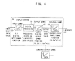
- FIG. 4 illustrates an exemplary display system implementing a digital input gamma function and reduced-gate-count cubic output and panel gamma functions.
- FIG. 5 is a graph conceptually illustrating an exemplary third order polynomial output gamma function of a further embodiment of the invention, in which the gamma function also includes a linear portion similar to an sRGB standard gamma function.
- FIG. 6 is a graph conceptually illustrating an exemplary third order polynomial input gamma function of a further embodiment of the invention, in which the gamma function also includes a linear portion similar to an sRGB standard gamma function.
- a display's gamma block should output digital gamma-corrected image data, rather than analog signals.
- the output of the gamma block is then suitable for digital image processing.
- FIG. 2 an Input Gamma block gamma corrects input image data much like the Panel Gamma block of FIG. 1 , except that the output of the Input Gamma block is digital, not analog, data.
- the Input Gamma block can also increase the bit depth of the data, e.g. from 8-bit to 11-bit data. Desired digital image processing is then performed in the Digital Processing block.
- the output data can simply be converted back to the appropriate bit depth (here, 8 bits), and converted to analog signals for driving the display.
- This is shown here as an Output Gamma block that converts data from the higher bit depth used by the Digital Processing Block back down to 8-bit data, and a Panel Gamma block that converts this 8-bit digital data to analog output for display.
- FIG. 3 also suffers from drawbacks.
- the Output Gamma block of FIG. 3 often requires excessively high gate count to implement.
- the invention employs a cubic approximation to a panel's gamma function. This results in a significant savings in gate count, and thus an improvement in the size, complexity, power consumption, and expense of image processing hardware.
- FIG. 4 is a block diagram illustration of an exemplary display system implementing a third order polynomial output gamma function according to an embodiment of the invention.
- display system 10 can be any image display system, but is commonly implemented as a flat panel display (e.g., LED, OLED, etc.) system.
- the display system 10 includes an input gamma block 20 applying an input gamma function to input image data, a digital processing block 30 performing various processing operations on the image data, an output gamma block 40 applying an output gamma function to cancel the panel's gamma function, and a panel gamma block 50 implementing the panel's gamma function, which is substantially the inverse of the output gamma function from block 40 .
- the input gamma block 20 applies a “standard” gamma function to the input image data, i.e. a power law function such as equation (1), typically to comply with established standards such as the sRGB standard.
- the digital processing block 30 processes the gamma-corrected image data to improve image quality. Any such processing operations are contemplated.
- the processing block 30 can perform any one or more of sub-pixel rendering, filtering, contrast and color enhancement, and the like.
- Output gamma block 40 then applies a third order polynomial gamma function to the image data, whereupon the image data is converted to 8-bit format and the panel gamma block 50 applies the panel gamma function, which is substantially the inverse of the gamma function applied by output gamma block 40 .
- the gamma functions of the blocks 40 , 50 effectively cancel each other, with the net effect being that the only gamma function applied to the output image is that from input gamma block 20 .
- the above described blocks 20 - 50 can be implemented as circuits that perform the respective tasks described herein.
- a stream of image data is input to display system 10 and sent to the input gamma block 20 .
- this image data is in an 8-bit format, as is common in sRGB images and other images conforming to many current display standards.
- the input gamma block 20 applies a first gamma function to the 8-bit image data, and also upconverts (i.e. increases the bit depth of) the data to an 11-bit format via known methods.
- the input gamma block 20 sends this upconverted, gamma-decoded data to digital processing block 30 , which performs its operations on the 11-bit data.
- the digital processing block 30 then sends its output to output gamma block 40 , which applies a second gamma function to the output of digital processing block 30 , and also downconverts (decreases the bit depth of) this data back to the bit depth of the input image data.
- the output gamma block 40 converts the 11-bit output of the digital processing block 30 back to 8-bit data for output to the panel gamma block 40 .
- the panel gamma block 50 then applies a third gamma function to the 8-bit image data, where this third gamma function is largely the inverse of the second gamma function.
- this third gamma function is largely the inverse of the second gamma function.
- the third gamma function “cancels” the second gamma function, with the net effect being that the output luminance of the display system 30 is linear with respect to the input data, so that effectively the only gamma correction applied to the image data is the first gamma function from input gamma block 20 .
- bit depth conversions can take place in any suitable blocks, whether shown in FIG. 4 or not.
- block 30 may also operate on image data of any other bit depth, with input gamma block 20 converting the image data accordingly.
- bit depth conversions may be simple conversions of one bit depth to another, or may include data for other image processing operations.
- the output gamma block 40 may perform straightforward conversions of 11-bit data to 8-bit data, or may convert the 11-bit output of digital processing block 11 to 8-bit data, along with 2 dither bits for performing dithering operations on the 1-bit output image data. Any other form and manner of bit depth conversions are also contemplated.
- input gamma block 20 implements a gamma function that is a “standard” gamma function, i.e. a known gamma function that is typically applied in conventional display systems.
- This gamma function is typically a power-law function which, as above, often requires significant gate count to implement.
- the output gamma block 40 and panel gamma block 50 respectively apply a reduced gate count gamma function and its inverse.
- the gamma function implemented by output gamma block 40 is a third order polynomial function, i.e. a cubic polynomial function of the form:
- A, B, and C are coefficients that can take on any suitable value.
- the coefficients A, B, C can be chosen in any manner. For example, they can be chosen so as to provide a best fit to a gamma function specified by a desired standard, or may be chosen simply to provide a desired display output.
- the coefficients can also be chosen by specifying desired boundary conditions that a gamma function should meet. For example, it may be desirable to specify that the output gamma curve be zero and have a starting slope start_s1 at its origin, and have an ending slope end_s1 at its normalized end point (x2, y2) (where the end point is normalized to 1). Equations for A, B, and C thus become:
- the normalized end point can be chosen as (1, 0.5) rather than (1, 1), in order to produce a gamma function that both shifts state-densities and reduces bit depth by one bit. This is desirable in cases where, for example, the output gamma block 40 has 11-bit data input and 10-bit data out.
- Panel gamma block 50 implements the substantial inverse of the gamma function of output gamma block 40 .
- block 50 would implement the inverse function 0.5x 3 +0.5x.
- the “inverse” may be the precise mathematical inverse of the function implemented by output gamma block 40 , or may be any function that results in a substantially (though not necessarily exactly) linear luminance function, as shown by the graph of combined output gamma at the bottom of FIG. 4 .
- the panel gamma block 50 can follow a conventional digital/analog design, with digital input values producing output analog levels that in turn control the luminance of each subpixel or display element.
- the circuit design is roughly optimized not for a 2.2 gamma characteristic, but rather for a characteristic that is the “inverse” of the output gamma cubic polynomial function.
- the detailed characteristics of this functional block can be defined by register parameters, in known fashion. These parameters can be tuned by input of the appropriate values in the registers, in such a way as to achieve a more precise “inverse” of the output gamma cubic polynomial function (or any other function, as desired).
- systems of the invention allow for digital processing of gamma-corrected signals without the added cost resulting from implementation of high-gate-count power law functions.
- the cubic polynomial output gamma function may be a cubic function over its entire range of input values, or may be of differing order in certain ranges.
- the cubic polynomial of embodiments of the invention may include a linear portion near its origin.
- some third order polynomials according to the invention may be linear from the origin to point A, and cubic beyond A.
- the invention contemplates any value of A.
- the invention also contemplates any alternative values for the linear and cubic portions of the output gamma function, as well as any values of point A.
- low grey levels were mapped to output luminance levels that did not strictly follow the “inverse” guideline. Rather, they were tuned to appropriate lower levels that generated smooth results when displaying dark gradient test patterns.
- Such mapping is particularly desirable when reducing or compensating for excessively high digital values that may sometimes originate from a straight-line linear (non-cubic) portion at the low-end of the input gamma characteristic.
- the invention also contemplates using a similar cubic polynomial to approximate the 2.2 power-law gamma function of input gamma block 20 .
- the invention contemplates any form for the input gamma function approximation.
- the invention contemplates an input gamma function that has an initial linear portion, followed by a cubic approximation of a power-law gamma function. That is, the input gamma function approximation can take on any of the forms for the output and/or panel gamma functions described above.
- This can include gamma functions implemented as cubic functions or functions of any other polynomial order, as well as functions that include portions of lower order, such as linear portions, quadratic portions, or the like. Such polynomial functions can have coefficients of any suitable value.
- These gamma functions can be implemented as input gamma functions or as output and/or panel gamma functions. The embodiments were chosen and described in order to best explain the principles of the invention and its practical applications, to thereby enable others skilled in the art to best utilize the invention and various embodiments with various modifications as are suited to the particular use contemplated.
Landscapes
- Engineering & Computer Science (AREA)
- Physics & Mathematics (AREA)
- Computer Hardware Design (AREA)
- General Physics & Mathematics (AREA)
- Theoretical Computer Science (AREA)
- Picture Signal Circuits (AREA)
- Liquid Crystal Display Device Control (AREA)
- Control Of Indicators Other Than Cathode Ray Tubes (AREA)
- Processing Of Color Television Signals (AREA)
Abstract
Description
- This invention relates generally to flat panel displays. More specifically, this invention relates to reduced gate count gamma correction.
- In digital image processing, an image is typically represented as a number of pixels. Each pixel's color is defined by the color's coordinates in some color space, e.g. sRGB. The display converts the color coordinates to “grey levels” which are then used to define electrical signals (e.g. voltages) that determine luminous states of corresponding areas on the screen of the display. Sometimes, the color coordinates themselves can be used as grey levels. Prior to display, these grey levels are usually adjusted by some function (usually called a “gamma function”, “gamma transfer function”, “gamma transfer characteristic”, or “gamma curve”).
- For many displays, the gamma function is non-linear, and can be approximated by a power relationship:
-
L=x γ (1) - where L is the normalized luminance, x is the grey level, and γ is a constant for the display. In many CRTs (Cathode Ray Tubes), LCDs (Liquid Crystal Displays), and some other types of devices, γ is about 2.2. However, the relationship (1) and/or γ value are approximate, and can vary. Such variation can be adjusted or corrected for by, for example, using look-up tables (LUTs) tabulating values for a specific relationship that may differ somewhat from (1).
- Therefore, with reference to
FIG. 1 , conventional systems often apply a single gamma function such as (1) to input image data (e.g., sRGB data received from a transmission) as part of some current widely-used image display standards, e.g. to correctly display sRGB images. More specifically, as shown inFIG. 1 , conventional systems employ a single Panel Gamma block that receives digital input image data (typically, 8-bit digital image data intended for display, such as output from a graphics card), applies gamma function (1) to the image data and converts it to analog, and outputs the gamma-corrected, analog luminance values that drive a display. - A typical color display is associated with a set of primary colors, e.g. red, green and blue. The display accepts separate grey levels for each of the primary colors (i.e. for each “channel”). The gamma functions can be different for different channels, and therefore separate LUTs can be provided for each channel.
- For example, a color LCD may include a number of red, green and blue subpixels. The subpixels have identical liquid crystal cells, but have color filters of different colors (red, green, blue). The liquid crystal cells however have different optical activity with respect to wavelength and hence to color. Depending on the spectral bandwidth of the color filters, such optical activity can result in unequal luminance gamma transfer characteristics amongst the R, G, B channels. In addition, the optical activity can result in chrominance deviations (e.g. hue deviations) within each channel. The unequal gamma transfer characteristics can be corrected using the separate LUTs for each channel.
- The invention can be implemented in a number of ways, including as an apparatus, a method, and as a computer-readable medium.
- In one embodiment, a display system comprises a gamma preconditioning circuit configured to receive image data, to apply a first gamma function to the image data so as to generate gamma-compensated image data, and to output the gamma-compensated image data. The display system also includes a processing circuit in electronic communication with the gamma preconditioning circuit, the processing circuit configured to receive the gamma-compensated image data, to perform an image processing operation on the gamma-compensated image data so as to generate processed image data, and to output the processed image data. Also included is an output gamma circuit in electronic communication with the processing circuit, the output gamma circuit configured to receive the processed image data, to apply a second gamma function to the processed image data so as to generate gamma-encoded processed image data, and to output the gamma-encoded processed image data, wherein the second gamma function comprises a third order polynomial function.
- In another embodiment, a method of gamma-correcting image data comprises applying a first gamma function to image data, so as to generate first compensated image data, as well as applying a second gamma function to the first compensated image data, so as to generate second compensated image data. The second gamma function comprises a third order polynomial function. The method also includes applying a third gamma function to the second compensated image data so as to generate third compensated image data, wherein the third gamma function is substantially an inverse of the third order polynomial function.
- In a further embodiment, a non-transitory computer-readable medium comprises one or more non-transitory computer-readable mediums collectively storing instructions for carrying out a method. The method comprises applying a first gamma function to image data, so as to generate first compensated image data, and applying a second gamma function to the first compensated image data, so as to generate second compensated image data. The second gamma function comprises a third order polynomial function. The method also includes applying a third gamma function to the second compensated image data so as to generate third compensated image data, wherein the third gamma function is substantially an inverse of the third order polynomial function.
- Other aspects and advantages of the invention will become apparent from the following detailed description taken in conjunction with the accompanying drawings which illustrate, by way of example, the principles of the invention.
- For a better understanding of the invention, reference should be made to the following detailed description taken in conjunction with the accompanying drawings, in which:
-
FIG. 1 is a block diagram representation of a conventional display system that applies a single power-law gamma function to its input data. -
FIG. 2 illustrates an exemplary display system employing a digital input gamma function and linear output and panel gamma functions. -
FIG. 3 illustrates a further exemplary display system employing a digital input gamma function and power law output and panel gamma functions. -
FIG. 4 illustrates an exemplary display system implementing a digital input gamma function and reduced-gate-count cubic output and panel gamma functions. -
FIG. 5 is a graph conceptually illustrating an exemplary third order polynomial output gamma function of a further embodiment of the invention, in which the gamma function also includes a linear portion similar to an sRGB standard gamma function. -
FIG. 6 is a graph conceptually illustrating an exemplary third order polynomial input gamma function of a further embodiment of the invention, in which the gamma function also includes a linear portion similar to an sRGB standard gamma function. - Like reference numerals refer to corresponding parts throughout the drawings.
- As above, conventional systems employ a single Panel Gamma block that is implemented as an analog circuit, and that applies a power law gamma function such as equation (1) to image data, largely to comply with current standards such as the sRGB standard. However, this approach presents difficulties if one wishes to apply digital image processing to gamma-corrected data, as the output of the panel gamma block of
FIG. 1 is analog, rather than digital. - To apply digital image processing methods to image data, a display's gamma block should output digital gamma-corrected image data, rather than analog signals. The output of the gamma block is then suitable for digital image processing. This approach is illustrated in
FIG. 2 . Here, an Input Gamma block gamma corrects input image data much like the Panel Gamma block ofFIG. 1 , except that the output of the Input Gamma block is digital, not analog, data. As much digital image processing is performed at higher than 8-bit bit depths, the Input Gamma block can also increase the bit depth of the data, e.g. from 8-bit to 11-bit data. Desired digital image processing is then performed in the Digital Processing block. As the data is already gamma-corrected, the output data can simply be converted back to the appropriate bit depth (here, 8 bits), and converted to analog signals for driving the display. This is shown here as an Output Gamma block that converts data from the higher bit depth used by the Digital Processing Block back down to 8-bit data, and a Panel Gamma block that converts this 8-bit digital data to analog output for display. As neither the Output Gamma nor the Panel Gamma block needs to apply a gamma function, each is shown as simply mapping input luminance to output luminance uniformly, i.e. applying linear function y=x, where x is the input luminance and y is the output luminance of each block. - One would think that the approach of
FIG. 2 would be sufficient. However, this approach suffers from disadvantages. For example, the relatively flat initial slope of the curve of equation (1) compresses many smaller input luminance values into a range of very small output luminance values. When converted back to 8-bit depth, many of these small luminance values are truncated to zero, compromising the accuracy of the resulting image and creating undesirable artifacts such as dark shadows and dark gradients that are rendered entirely black. - To avoid these undesirable effects, one may think to instead implement a system such as that shown in
FIG. 3 , with the Output Gamma and Panel Gamma blocks implementing a γ=1/2.2 and γ=2.2 function, respectively. That is, the Output Gamma block ofFIG. 3 both reduces the bit depth of the image data to 8 bits, and applies a γ=1/2.2 function, as shown. The Panel Gamma block ofFIG. 3 is thus a conventional Panel Gamma block such as that ofFIG. 1 , which applies a γ=2.2 function and converts the digital data to analog signals. This system does not have the truncation problems ofFIG. 2 , as the high initial slope of the γ=1/2.2 function effectively re-expands the low input luminance values that were compressed by the initial slope of the Input Gamma block. That is, low luminance values are amplified and spread out by the high initial slope of the γ=1/2.2 function, increasing their luminance values and making them more likely to avoid truncation. Once converted back to 8-bit data, the Panel Gamma block applies the inverse γ=2.2 function to effectively cancel the gamma function of the Output Gamma block, with the net effect being that only the gamma function of the Input Gamma block is applied. - However, the configuration of
FIG. 3 also suffers from drawbacks. In particular, the γ=1/2.2 function is difficult to implement with low gate count. Thus, the Output Gamma block ofFIG. 3 often requires excessively high gate count to implement. - Embodiments of the invention solve this problem by implementing a polynomial approximation to the γ=1/2.2 function, rather than implementing a power law. In one embodiment, the invention employs a cubic approximation to a panel's gamma function. This results in a significant savings in gate count, and thus an improvement in the size, complexity, power consumption, and expense of image processing hardware.
-
FIG. 4 is a block diagram illustration of an exemplary display system implementing a third order polynomial output gamma function according to an embodiment of the invention. Here,display system 10 can be any image display system, but is commonly implemented as a flat panel display (e.g., LED, OLED, etc.) system. Thedisplay system 10 includes aninput gamma block 20 applying an input gamma function to input image data, adigital processing block 30 performing various processing operations on the image data, anoutput gamma block 40 applying an output gamma function to cancel the panel's gamma function, and apanel gamma block 50 implementing the panel's gamma function, which is substantially the inverse of the output gamma function fromblock 40. - The
input gamma block 20 applies a “standard” gamma function to the input image data, i.e. a power law function such as equation (1), typically to comply with established standards such as the sRGB standard. Thedigital processing block 30 processes the gamma-corrected image data to improve image quality. Any such processing operations are contemplated. For example, theprocessing block 30 can perform any one or more of sub-pixel rendering, filtering, contrast and color enhancement, and the like.Output gamma block 40 then applies a third order polynomial gamma function to the image data, whereupon the image data is converted to 8-bit format and thepanel gamma block 50 applies the panel gamma function, which is substantially the inverse of the gamma function applied byoutput gamma block 40. Thus, the gamma functions of theblocks input gamma block 20. As is known, the above described blocks 20-50 can be implemented as circuits that perform the respective tasks described herein. - In operation, a stream of image data is input to display
system 10 and sent to theinput gamma block 20. Typically, this image data is in an 8-bit format, as is common in sRGB images and other images conforming to many current display standards. Theinput gamma block 20 applies a first gamma function to the 8-bit image data, and also upconverts (i.e. increases the bit depth of) the data to an 11-bit format via known methods. Thus, the output ofblock 20 is commonly 11-bit image data that has been gamma decoded by a γ=2.2 or similar gamma function. Theinput gamma block 20 sends this upconverted, gamma-decoded data todigital processing block 30, which performs its operations on the 11-bit data. Thedigital processing block 30 then sends its output tooutput gamma block 40, which applies a second gamma function to the output ofdigital processing block 30, and also downconverts (decreases the bit depth of) this data back to the bit depth of the input image data. In the sRGB example, theoutput gamma block 40 converts the 11-bit output of thedigital processing block 30 back to 8-bit data for output to thepanel gamma block 40. Thepanel gamma block 50 then applies a third gamma function to the 8-bit image data, where this third gamma function is largely the inverse of the second gamma function. As shown by the “Combined Output Gamma” box ofFIG. 4 , the third gamma function “cancels” the second gamma function, with the net effect being that the output luminance of thedisplay system 30 is linear with respect to the input data, so that effectively the only gamma correction applied to the image data is the first gamma function frominput gamma block 20. - It should be noted that, while some blocks of
display system 10 convert images from one bit depth to another, the invention is not limited to any particular bit depths, and the bit depth conversions can take place in any suitable blocks, whether shown inFIG. 4 or not. For example, while it may be desirable fordigital processing block 30 to operate on image data having a bit depth of 11 bits, block 30 may also operate on image data of any other bit depth, withinput gamma block 20 converting the image data accordingly. It should also be noted that bit depth conversions may be simple conversions of one bit depth to another, or may include data for other image processing operations. For instance, theoutput gamma block 40 may perform straightforward conversions of 11-bit data to 8-bit data, or may convert the 11-bit output of digital processing block 11 to 8-bit data, along with 2 dither bits for performing dithering operations on the 1-bit output image data. Any other form and manner of bit depth conversions are also contemplated. - In
display system 10,input gamma block 20 implements a gamma function that is a “standard” gamma function, i.e. a known gamma function that is typically applied in conventional display systems. This gamma function is typically a power-law function which, as above, often requires significant gate count to implement. In contrast, theoutput gamma block 40 andpanel gamma block 50 respectively apply a reduced gate count gamma function and its inverse. In one embodiment, the gamma function implemented byoutput gamma block 40 is a third order polynomial function, i.e. a cubic polynomial function of the form: -
y=Ax 3 +Bx 2 +Cx (2) - Where y is the digital output value of the output gamma function, and A, B, and C are coefficients that can take on any suitable value. The coefficients A, B, C can be chosen in any manner. For example, they can be chosen so as to provide a best fit to a gamma function specified by a desired standard, or may be chosen simply to provide a desired display output. The coefficients can also be chosen by specifying desired boundary conditions that a gamma function should meet. For example, it may be desirable to specify that the output gamma curve be zero and have a starting slope start_s1 at its origin, and have an ending slope end_s1 at its normalized end point (x2, y2) (where the end point is normalized to 1). Equations for A, B, and C thus become:
-
A=(start— s1+end— s1)/x22−2(y2/x23) -
B=3(y2/x22)−(2start— s1+end— s1)/x2 -
C=start— s1 (3) - Here, the normalized end point can be chosen as (1, 0.5) rather than (1, 1), in order to produce a gamma function that both shifts state-densities and reduces bit depth by one bit. This is desirable in cases where, for example, the
output gamma block 40 has 11-bit data input and 10-bit data out. For this normalized end point, and for start_s1=1 and end_s1=0.25, solving equations (3) results in a gamma function γ=0.25x3−0.75x2+x. Alternatively, for a normalized end point of (1, 1), the coefficients double, resulting in a gamma function γ=0.5x3−1.5x2+2x. This latter function is particularly desirable from a gate count standpoint, in that the coefficients 0.5, −1.5, and 2 can be implemented as simple binary shifts and additions, without need for more costly multiplication or division operations. - Varying any of these conditions will result in somewhat different gamma functions y, with differing coefficients A, B, C.
-
Panel gamma block 50 implements the substantial inverse of the gamma function ofoutput gamma block 40. Thus, for y=0.5x3−1.5x2+2x, block 50 would implement the inverse function 0.5x3+0.5x. Here, the “inverse” may be the precise mathematical inverse of the function implemented byoutput gamma block 40, or may be any function that results in a substantially (though not necessarily exactly) linear luminance function, as shown by the graph of combined output gamma at the bottom ofFIG. 4 . - The
panel gamma block 50 can follow a conventional digital/analog design, with digital input values producing output analog levels that in turn control the luminance of each subpixel or display element. However, the circuit design is roughly optimized not for a 2.2 gamma characteristic, but rather for a characteristic that is the “inverse” of the output gamma cubic polynomial function. The detailed characteristics of this functional block can be defined by register parameters, in known fashion. These parameters can be tuned by input of the appropriate values in the registers, in such a way as to achieve a more precise “inverse” of the output gamma cubic polynomial function (or any other function, as desired). - One of skill will observe that the configuration of
FIG. 4 is advantageous in that it yields largely the same benefits as the system ofFIG. 3 , yet does so without implementing a high-gate-count γ=1/2.2 block. Instead, a lower gate count polynomial block is implemented. Thus, systems of the invention allow for digital processing of gamma-corrected signals without the added cost resulting from implementation of high-gate-count power law functions. - The cubic polynomial output gamma function may be a cubic function over its entire range of input values, or may be of differing order in certain ranges. For example, as with the standard sRGB gamma function, the cubic polynomial of embodiments of the invention may include a linear portion near its origin. For instance, with reference to
FIG. 5 , some third order polynomials according to the invention may be linear from the origin to point A, and cubic beyond A. The invention contemplates any value of A. The invention also contemplates any alternative values for the linear and cubic portions of the output gamma function, as well as any values of point A. For example, in one implementation of this inverse cubic function, low grey levels were mapped to output luminance levels that did not strictly follow the “inverse” guideline. Rather, they were tuned to appropriate lower levels that generated smooth results when displaying dark gradient test patterns. Such mapping is particularly desirable when reducing or compensating for excessively high digital values that may sometimes originate from a straight-line linear (non-cubic) portion at the low-end of the input gamma characteristic. - The invention also contemplates using a similar cubic polynomial to approximate the 2.2 power-law gamma function of
input gamma block 20. In this case, the digital input gamma block can be relatively easily implemented in a form similar to equation (2), where y is the normalized digital output value of the input gamma block, x is the input value to that block, and exemplary values of the coefficients are A=0.25, B=0.75, C=0. Any other values for A, B, and C can also be used, but these values are often desirable in that they can be implemented with relatively simple shift and add operations, rather than full multiplications. As with the output gamma function approximations, the invention contemplates any form for the input gamma function approximation. For example, as shown inFIG. 6 , the invention contemplates an input gamma function that has an initial linear portion, followed by a cubic approximation of a power-law gamma function. That is, the input gamma function approximation can take on any of the forms for the output and/or panel gamma functions described above. - The foregoing description, for purposes of explanation, used specific nomenclature to provide a thorough understanding of the invention. However, it will be apparent to one skilled in the art that the specific details are not required in order to practice the invention. Thus, the foregoing descriptions of specific embodiments of the present invention are presented for purposes of illustration and description. They are not intended to be exhaustive or to limit the invention to the precise forms disclosed. Many modifications and variations are possible in view of the above teachings. For example, the invention contemplates any gamma functions, and their inverses, that can be implemented with lower gate count than a typical power law gamma function. This can include gamma functions implemented as cubic functions or functions of any other polynomial order, as well as functions that include portions of lower order, such as linear portions, quadratic portions, or the like. Such polynomial functions can have coefficients of any suitable value. These gamma functions can be implemented as input gamma functions or as output and/or panel gamma functions. The embodiments were chosen and described in order to best explain the principles of the invention and its practical applications, to thereby enable others skilled in the art to best utilize the invention and various embodiments with various modifications as are suited to the particular use contemplated.
Claims (27)
Priority Applications (2)
| Application Number | Priority Date | Filing Date | Title |
|---|---|---|---|
| US13/074,978 US8717378B2 (en) | 2011-03-29 | 2011-03-29 | Method and apparatus for reduced gate count gamma correction |
| KR1020120026897A KR101938298B1 (en) | 2011-03-29 | 2012-03-16 | display system, method for gamma-correcting image data using the same, and computer-readable media for implementing the method |
Applications Claiming Priority (1)
| Application Number | Priority Date | Filing Date | Title |
|---|---|---|---|
| US13/074,978 US8717378B2 (en) | 2011-03-29 | 2011-03-29 | Method and apparatus for reduced gate count gamma correction |
Publications (2)
| Publication Number | Publication Date |
|---|---|
| US20120249574A1 true US20120249574A1 (en) | 2012-10-04 |
| US8717378B2 US8717378B2 (en) | 2014-05-06 |
Family
ID=46926605
Family Applications (1)
| Application Number | Title | Priority Date | Filing Date |
|---|---|---|---|
| US13/074,978 Active 2033-01-04 US8717378B2 (en) | 2011-03-29 | 2011-03-29 | Method and apparatus for reduced gate count gamma correction |
Country Status (2)
| Country | Link |
|---|---|
| US (1) | US8717378B2 (en) |
| KR (1) | KR101938298B1 (en) |
Cited By (6)
| Publication number | Priority date | Publication date | Assignee | Title |
|---|---|---|---|---|
| US20140253421A1 (en) * | 2013-03-06 | 2014-09-11 | Sony Corporation | Display, display drive circuit, display drive method, and electronic apparatus |
| US20150146107A1 (en) * | 2013-11-26 | 2015-05-28 | Apple Inc. | Methods to Reduce Bit-Depth Required for Linearizing Data |
| US20150356946A1 (en) * | 2014-06-05 | 2015-12-10 | Mstar Semiconductor, Inc. | Gamma correction circuit and gamma correction method |
| US9282223B1 (en) * | 2014-08-13 | 2016-03-08 | Au Optronics Corp. | Curved display apparatus and gamma correction method thereof |
| TWI810952B (en) * | 2022-05-26 | 2023-08-01 | 大陸商北京集創北方科技股份有限公司 | LED display driver chip capable of reducing data transmission volume, LED display device and information processing device |
| US20240013692A1 (en) * | 2022-07-08 | 2024-01-11 | Apple Inc. | Content-Aware Dynamic Power Converter Switching for Power Optimization |
Families Citing this family (2)
| Publication number | Priority date | Publication date | Assignee | Title |
|---|---|---|---|---|
| KR102024064B1 (en) | 2013-01-15 | 2019-09-24 | 삼성디스플레이 주식회사 | Organic light emitting display device |
| CN106595871A (en) * | 2016-12-16 | 2017-04-26 | 中国科学院长春光学精密机械与物理研究所 | Infrared target simulator grayscale adaptive linear correction device and correction method |
Citations (7)
| Publication number | Priority date | Publication date | Assignee | Title |
|---|---|---|---|---|
| US6064396A (en) * | 1994-10-24 | 2000-05-16 | Ricoh Company, Ltd. | Two-step gamma correction method and system |
| US20050276502A1 (en) * | 2004-06-10 | 2005-12-15 | Clairvoyante, Inc. | Increasing gamma accuracy in quantized systems |
| US20080030526A1 (en) * | 2001-05-09 | 2008-02-07 | Clairvoyante, Inc | Methods and Systems for Sub-Pixel Rendering with Adaptive Filtering |
| US20090051818A1 (en) * | 2007-08-21 | 2009-02-26 | Nec Electronics Corporation | Video signal processing device, video signal processing method and display device |
| US20090195547A1 (en) * | 2008-02-06 | 2009-08-06 | Canon Kabushiki Kaisha | Image signal processing apparatus and image signal processing method |
| US20090284546A1 (en) * | 2008-05-19 | 2009-11-19 | Samsung Electronics Co., Ltd. | Input gamma dithering systems and methods |
| US20110148942A1 (en) * | 2009-12-22 | 2011-06-23 | Renesas Electronics Corporation | Display data correction by numerical operation suitable for display panel driver |
Family Cites Families (1)
| Publication number | Priority date | Publication date | Assignee | Title |
|---|---|---|---|---|
| US8203523B2 (en) * | 2009-07-29 | 2012-06-19 | Samsung Electronics Co., Ltd. | Method and apparatus for selectively applying input gamma dithering |
-
2011
- 2011-03-29 US US13/074,978 patent/US8717378B2/en active Active
-
2012
- 2012-03-16 KR KR1020120026897A patent/KR101938298B1/en active Active
Patent Citations (7)
| Publication number | Priority date | Publication date | Assignee | Title |
|---|---|---|---|---|
| US6064396A (en) * | 1994-10-24 | 2000-05-16 | Ricoh Company, Ltd. | Two-step gamma correction method and system |
| US20080030526A1 (en) * | 2001-05-09 | 2008-02-07 | Clairvoyante, Inc | Methods and Systems for Sub-Pixel Rendering with Adaptive Filtering |
| US20050276502A1 (en) * | 2004-06-10 | 2005-12-15 | Clairvoyante, Inc. | Increasing gamma accuracy in quantized systems |
| US20090051818A1 (en) * | 2007-08-21 | 2009-02-26 | Nec Electronics Corporation | Video signal processing device, video signal processing method and display device |
| US20090195547A1 (en) * | 2008-02-06 | 2009-08-06 | Canon Kabushiki Kaisha | Image signal processing apparatus and image signal processing method |
| US20090284546A1 (en) * | 2008-05-19 | 2009-11-19 | Samsung Electronics Co., Ltd. | Input gamma dithering systems and methods |
| US20110148942A1 (en) * | 2009-12-22 | 2011-06-23 | Renesas Electronics Corporation | Display data correction by numerical operation suitable for display panel driver |
Cited By (9)
| Publication number | Priority date | Publication date | Assignee | Title |
|---|---|---|---|---|
| US20140253421A1 (en) * | 2013-03-06 | 2014-09-11 | Sony Corporation | Display, display drive circuit, display drive method, and electronic apparatus |
| US9905171B2 (en) * | 2013-03-06 | 2018-02-27 | Sony Corporation | Display, display drive circuit, display drive method, and electronic apparatus |
| US20150146107A1 (en) * | 2013-11-26 | 2015-05-28 | Apple Inc. | Methods to Reduce Bit-Depth Required for Linearizing Data |
| US20150356946A1 (en) * | 2014-06-05 | 2015-12-10 | Mstar Semiconductor, Inc. | Gamma correction circuit and gamma correction method |
| US9747865B2 (en) * | 2014-06-05 | 2017-08-29 | Mstar Semiconductor, Inc. | Gamma correction circuit and gamma correction method |
| US9282223B1 (en) * | 2014-08-13 | 2016-03-08 | Au Optronics Corp. | Curved display apparatus and gamma correction method thereof |
| TWI810952B (en) * | 2022-05-26 | 2023-08-01 | 大陸商北京集創北方科技股份有限公司 | LED display driver chip capable of reducing data transmission volume, LED display device and information processing device |
| US20240013692A1 (en) * | 2022-07-08 | 2024-01-11 | Apple Inc. | Content-Aware Dynamic Power Converter Switching for Power Optimization |
| US12394345B2 (en) * | 2022-07-08 | 2025-08-19 | Apple Inc. | Content-aware dynamic power converter switching for power optimization |
Also Published As
| Publication number | Publication date |
|---|---|
| KR101938298B1 (en) | 2019-04-12 |
| KR20120112034A (en) | 2012-10-11 |
| US8717378B2 (en) | 2014-05-06 |
Similar Documents
| Publication | Publication Date | Title |
|---|---|---|
| US8717378B2 (en) | Method and apparatus for reduced gate count gamma correction | |
| EP2148300B1 (en) | Colour dithering | |
| US7176935B2 (en) | Gamut conversion system and methods | |
| US7589743B2 (en) | Hue angle calculation system and methods | |
| CN104981861B (en) | Signal conversion device and method | |
| JP5593921B2 (en) | Liquid crystal display | |
| US20080266315A1 (en) | Method and apparatus for displaying images having wide color gamut | |
| CN101794565B (en) | Image display method, device and system | |
| US9196204B2 (en) | Image processing apparatus and image processing method | |
| US10347198B2 (en) | Image displaying methods and display devices | |
| US7859499B2 (en) | Display apparatus | |
| US9390660B2 (en) | Image control for displays | |
| KR101788681B1 (en) | Color correction to compensate for displays' luminance and chrominance transfer characteristics | |
| CN100525471C (en) | Brightness control method and brightness control apparatus for controlling brightness, and computer system | |
| CN103026401A (en) | Display control for multi-primary display | |
| CN108322683A (en) | Display unit, image processing unit and display methods | |
| US9171513B2 (en) | Luminance adjustment part, display apparatus having the luminance adjustment part, and method for adjusting luminance | |
| CN101807384A (en) | Image signal processing system and image processing method | |
| JP4613702B2 (en) | Gamma correction, image processing method and program, and gamma correction circuit, image processing apparatus, and display apparatus | |
| CN103000145B (en) | Multi-primary color liquid crystal display and its color signal conversion device and method | |
| TW201312531A (en) | Multi-primary color LCD and color signal conversion device and method thereof | |
| EP2482559A2 (en) | System and method for generating rgb primaries for a wide color gamut, and color encoding system using rgb primaries | |
| CN105684071A (en) | Signal generating device, signal generating program, signal generating method, and image display device | |
| WO2007055703A1 (en) | A system and method for enhancing the contrast ratio of an image | |
| CN101496092A (en) | Perceptual color matching method between two different multicolor displays |
Legal Events
| Date | Code | Title | Description |
|---|---|---|---|
| AS | Assignment |
Owner name: SAMSUNG ELECTRONICS CO., LTD., KOREA, REPUBLIC OF Free format text: ASSIGNMENT OF ASSIGNORS INTEREST;ASSIGNOR:BOTZAS, ANTHONY;REEL/FRAME:026044/0597 Effective date: 20110328 |
|
| AS | Assignment |
Owner name: SAMSUNG DISPLAY CO., LTD, KOREA, REPUBLIC OF Free format text: ASSIGNMENT OF ASSIGNORS INTEREST;ASSIGNOR:SAMSUNG ELECTRONICS, CO., LTD;REEL/FRAME:028990/0188 Effective date: 20120904 |
|
| FEPP | Fee payment procedure |
Free format text: PAYOR NUMBER ASSIGNED (ORIGINAL EVENT CODE: ASPN); ENTITY STATUS OF PATENT OWNER: LARGE ENTITY |
|
| STCF | Information on status: patent grant |
Free format text: PATENTED CASE |
|
| MAFP | Maintenance fee payment |
Free format text: PAYMENT OF MAINTENANCE FEE, 4TH YEAR, LARGE ENTITY (ORIGINAL EVENT CODE: M1551) Year of fee payment: 4 |
|
| MAFP | Maintenance fee payment |
Free format text: PAYMENT OF MAINTENANCE FEE, 8TH YEAR, LARGE ENTITY (ORIGINAL EVENT CODE: M1552); ENTITY STATUS OF PATENT OWNER: LARGE ENTITY Year of fee payment: 8 |
|
| MAFP | Maintenance fee payment |
Free format text: PAYMENT OF MAINTENANCE FEE, 12TH YEAR, LARGE ENTITY (ORIGINAL EVENT CODE: M1553); ENTITY STATUS OF PATENT OWNER: LARGE ENTITY Year of fee payment: 12 |