US20120249406A1 - Display Module, Display Device, and Liquid Crystal Television Set - Google Patents
Display Module, Display Device, and Liquid Crystal Television Set Download PDFInfo
- Publication number
- US20120249406A1 US20120249406A1 US13/420,053 US201213420053A US2012249406A1 US 20120249406 A1 US20120249406 A1 US 20120249406A1 US 201213420053 A US201213420053 A US 201213420053A US 2012249406 A1 US2012249406 A1 US 2012249406A1
- Authority
- US
- United States
- Prior art keywords
- positioning
- guide plate
- frame
- light guide
- positioning member
- Prior art date
- Legal status (The legal status is an assumption and is not a legal conclusion. Google has not performed a legal analysis and makes no representation as to the accuracy of the status listed.)
- Granted
Links
- 239000004973 liquid crystal related substance Substances 0.000 title claims description 51
- 229920005989 resin Polymers 0.000 claims abstract description 65
- 239000011347 resin Substances 0.000 claims abstract description 65
- 239000002184 metal Substances 0.000 claims abstract description 19
- 230000003287 optical effect Effects 0.000 claims description 38
- 230000007547 defect Effects 0.000 description 7
- 230000015572 biosynthetic process Effects 0.000 description 6
- XECAHXYUAAWDEL-UHFFFAOYSA-N acrylonitrile butadiene styrene Chemical compound C=CC=C.C=CC#N.C=CC1=CC=CC=C1 XECAHXYUAAWDEL-UHFFFAOYSA-N 0.000 description 2
- 239000004676 acrylonitrile butadiene styrene Substances 0.000 description 2
- 229920000122 acrylonitrile butadiene styrene Polymers 0.000 description 2
- 239000004417 polycarbonate Substances 0.000 description 2
- 229920005668 polycarbonate resin Polymers 0.000 description 2
- 229920000139 polyethylene terephthalate Polymers 0.000 description 2
- 239000005020 polyethylene terephthalate Substances 0.000 description 2
- 229920000178 Acrylic resin Polymers 0.000 description 1
- 239000004925 Acrylic resin Substances 0.000 description 1
- 210000002858 crystal cell Anatomy 0.000 description 1
- 238000009792 diffusion process Methods 0.000 description 1
- 230000000694 effects Effects 0.000 description 1
- 230000002401 inhibitory effect Effects 0.000 description 1
- 239000000463 material Substances 0.000 description 1
- -1 polyethylene terephthalate Polymers 0.000 description 1
Images


Classifications
-
- G—PHYSICS
- G09—EDUCATION; CRYPTOGRAPHY; DISPLAY; ADVERTISING; SEALS
- G09G—ARRANGEMENTS OR CIRCUITS FOR CONTROL OF INDICATING DEVICES USING STATIC MEANS TO PRESENT VARIABLE INFORMATION
- G09G3/00—Control arrangements or circuits, of interest only in connection with visual indicators other than cathode-ray tubes
- G09G3/20—Control arrangements or circuits, of interest only in connection with visual indicators other than cathode-ray tubes for presentation of an assembly of a number of characters, e.g. a page, by composing the assembly by combination of individual elements arranged in a matrix no fixed position being assigned to or needed to be assigned to the individual characters or partial characters
- G09G3/34—Control arrangements or circuits, of interest only in connection with visual indicators other than cathode-ray tubes for presentation of an assembly of a number of characters, e.g. a page, by composing the assembly by combination of individual elements arranged in a matrix no fixed position being assigned to or needed to be assigned to the individual characters or partial characters by control of light from an independent source
- G09G3/36—Control arrangements or circuits, of interest only in connection with visual indicators other than cathode-ray tubes for presentation of an assembly of a number of characters, e.g. a page, by composing the assembly by combination of individual elements arranged in a matrix no fixed position being assigned to or needed to be assigned to the individual characters or partial characters by control of light from an independent source using liquid crystals
-
- G—PHYSICS
- G02—OPTICS
- G02B—OPTICAL ELEMENTS, SYSTEMS OR APPARATUS
- G02B6/00—Light guides; Structural details of arrangements comprising light guides and other optical elements, e.g. couplings
- G02B6/0001—Light guides; Structural details of arrangements comprising light guides and other optical elements, e.g. couplings specially adapted for lighting devices or systems
- G02B6/0011—Light guides; Structural details of arrangements comprising light guides and other optical elements, e.g. couplings specially adapted for lighting devices or systems the light guides being planar or of plate-like form
- G02B6/0081—Mechanical or electrical aspects of the light guide and light source in the lighting device peculiar to the adaptation to planar light guides, e.g. concerning packaging
- G02B6/0086—Positioning aspects
- G02B6/0088—Positioning aspects of the light guide or other optical sheets in the package
-
- G—PHYSICS
- G02—OPTICS
- G02F—OPTICAL DEVICES OR ARRANGEMENTS FOR THE CONTROL OF LIGHT BY MODIFICATION OF THE OPTICAL PROPERTIES OF THE MEDIA OF THE ELEMENTS INVOLVED THEREIN; NON-LINEAR OPTICS; FREQUENCY-CHANGING OF LIGHT; OPTICAL LOGIC ELEMENTS; OPTICAL ANALOGUE/DIGITAL CONVERTERS
- G02F1/00—Devices or arrangements for the control of the intensity, colour, phase, polarisation or direction of light arriving from an independent light source, e.g. switching, gating or modulating; Non-linear optics
- G02F1/01—Devices or arrangements for the control of the intensity, colour, phase, polarisation or direction of light arriving from an independent light source, e.g. switching, gating or modulating; Non-linear optics for the control of the intensity, phase, polarisation or colour
- G02F1/13—Devices or arrangements for the control of the intensity, colour, phase, polarisation or direction of light arriving from an independent light source, e.g. switching, gating or modulating; Non-linear optics for the control of the intensity, phase, polarisation or colour based on liquid crystals, e.g. single liquid crystal display cells
- G02F1/133—Constructional arrangements; Operation of liquid crystal cells; Circuit arrangements
- G02F1/1333—Constructional arrangements; Manufacturing methods
- G02F1/1335—Structural association of cells with optical devices, e.g. polarisers or reflectors
- G02F1/1336—Illuminating devices
- G02F1/133602—Direct backlight
- G02F1/133608—Direct backlight including particular frames or supporting means
-
- G—PHYSICS
- G02—OPTICS
- G02F—OPTICAL DEVICES OR ARRANGEMENTS FOR THE CONTROL OF LIGHT BY MODIFICATION OF THE OPTICAL PROPERTIES OF THE MEDIA OF THE ELEMENTS INVOLVED THEREIN; NON-LINEAR OPTICS; FREQUENCY-CHANGING OF LIGHT; OPTICAL LOGIC ELEMENTS; OPTICAL ANALOGUE/DIGITAL CONVERTERS
- G02F1/00—Devices or arrangements for the control of the intensity, colour, phase, polarisation or direction of light arriving from an independent light source, e.g. switching, gating or modulating; Non-linear optics
- G02F1/01—Devices or arrangements for the control of the intensity, colour, phase, polarisation or direction of light arriving from an independent light source, e.g. switching, gating or modulating; Non-linear optics for the control of the intensity, phase, polarisation or colour
- G02F1/13—Devices or arrangements for the control of the intensity, colour, phase, polarisation or direction of light arriving from an independent light source, e.g. switching, gating or modulating; Non-linear optics for the control of the intensity, phase, polarisation or colour based on liquid crystals, e.g. single liquid crystal display cells
- G02F1/133—Constructional arrangements; Operation of liquid crystal cells; Circuit arrangements
- G02F1/1333—Constructional arrangements; Manufacturing methods
- G02F1/1335—Structural association of cells with optical devices, e.g. polarisers or reflectors
- G02F1/1336—Illuminating devices
- G02F1/133615—Edge-illuminating devices, i.e. illuminating from the side
-
- G—PHYSICS
- G02—OPTICS
- G02F—OPTICAL DEVICES OR ARRANGEMENTS FOR THE CONTROL OF LIGHT BY MODIFICATION OF THE OPTICAL PROPERTIES OF THE MEDIA OF THE ELEMENTS INVOLVED THEREIN; NON-LINEAR OPTICS; FREQUENCY-CHANGING OF LIGHT; OPTICAL LOGIC ELEMENTS; OPTICAL ANALOGUE/DIGITAL CONVERTERS
- G02F2201/00—Constructional arrangements not provided for in groups G02F1/00 - G02F7/00
- G02F2201/46—Fixing elements
-
- G—PHYSICS
- G02—OPTICS
- G02F—OPTICAL DEVICES OR ARRANGEMENTS FOR THE CONTROL OF LIGHT BY MODIFICATION OF THE OPTICAL PROPERTIES OF THE MEDIA OF THE ELEMENTS INVOLVED THEREIN; NON-LINEAR OPTICS; FREQUENCY-CHANGING OF LIGHT; OPTICAL LOGIC ELEMENTS; OPTICAL ANALOGUE/DIGITAL CONVERTERS
- G02F2201/00—Constructional arrangements not provided for in groups G02F1/00 - G02F7/00
- G02F2201/50—Protective arrangements
- G02F2201/503—Arrangements improving the resistance to shock
-
- Y—GENERAL TAGGING OF NEW TECHNOLOGICAL DEVELOPMENTS; GENERAL TAGGING OF CROSS-SECTIONAL TECHNOLOGIES SPANNING OVER SEVERAL SECTIONS OF THE IPC; TECHNICAL SUBJECTS COVERED BY FORMER USPC CROSS-REFERENCE ART COLLECTIONS [XRACs] AND DIGESTS
- Y10—TECHNICAL SUBJECTS COVERED BY FORMER USPC
- Y10S—TECHNICAL SUBJECTS COVERED BY FORMER USPC CROSS-REFERENCE ART COLLECTIONS [XRACs] AND DIGESTS
- Y10S248/00—Supports
- Y10S248/917—Video display screen support
-
- Y—GENERAL TAGGING OF NEW TECHNOLOGICAL DEVELOPMENTS; GENERAL TAGGING OF CROSS-SECTIONAL TECHNOLOGIES SPANNING OVER SEVERAL SECTIONS OF THE IPC; TECHNICAL SUBJECTS COVERED BY FORMER USPC CROSS-REFERENCE ART COLLECTIONS [XRACs] AND DIGESTS
- Y10—TECHNICAL SUBJECTS COVERED BY FORMER USPC
- Y10S—TECHNICAL SUBJECTS COVERED BY FORMER USPC CROSS-REFERENCE ART COLLECTIONS [XRACs] AND DIGESTS
- Y10S345/00—Computer graphics processing and selective visual display systems
- Y10S345/905—Display device with housing structure
Definitions
- the present invention relates to a display module, a display device, and a liquid crystal television set, and more particularly, it relates to a display module, a display device, and a liquid crystal television set each including a light guide plate made of resin and a frame made of metal.
- a display module including a light guide plate made of resin and a frame made of metal is known in general, as disclosed in Japanese Patent Laying-Open No. 2003-279934, for example.
- the aforementioned Japanese Patent Laying-Open No. 2003-279934 discloses an image display device including a displaying unit, a backlight unit having a light guide plate to apply light to the displaying unit, and a lower frame made of metal supporting the backlight unit.
- the light guide plate of the backlight unit in the image display device according to the aforementioned Japanese Patent Laying-Open No. 2003-279934 is formed with concave notches.
- a pair of bent portions extending upward are so formed on the lower frame as to correspond to the inner surfaces of the concave notches of the light guide plate, opposed to each other.
- the backlight unit is so arranged on the lower frame that the concave notches of the light guide plate of the backlight unit correspond to the pair of bent portions of the lower frame, whereby the backlight unit is positioned with respect to the lower frame.
- the concave notches of the light guide plate and the bent portions of the lower frame made of metal may come into contact with each other during assembling, transportation, or the like of the image display device in a state where the backlight unit is arranged on the lower frame.
- the light guide plate is generally made of resin that is more fragile than metal, whereby defects such as weak or breakage are disadvantageously easily formed on contact portions of the concave notches (positioning portions) of the light guide plate with the bent portions.
- the present invention has been proposed in order to solve the aforementioned problem, and an object of the present invention is to provide a display module, a display device, and a liquid crystal television set capable of inhibiting formation of a defect such as weak or breakage on a light guide plate due to contact of a positioning portion of the light guide plate made of resin with a frame made of metal.
- a display module includes a display portion, a light-emitting portion to apply light to the display portion, a light guide plate made of resin to guide the light from the light-emitting portion to the display portion, including a first positioning portion, a frame made of metal in which the light guide plate is arranged inside, including a hole, and a positioning member made of resin, including a second positioning portion so formed as to be capable of positioning the first positioning portion of the light guide plate in a state where the positioning member is so arranged as to cover the hole of the frame.
- the display module according to the first aspect of the present invention includes the light guide plate made of resin, including the first positioning portion and the positioning member made of resin, including the second positioning portion so formed as to be capable of positioning the first positioning portion of the light guide plate, whereby the light guide plate made of resin can be positioned by the positioning member made of resin.
- the positioning member made of resin is so arranged as to cover the hole of the frame, whereby the positioning member can inhibit leakage of light inside the display module from the hole to the outside.
- the first positioning portion of the light guide plate preferably has a concave shape
- the second positioning portion of the positioning member preferably has a shape corresponding to the concave shape of the first positioning portion.
- the light guide plate is so arranged that the concave first positioning portion of the light guide plate corresponds to the second positioning portion of the positioning member, whereby the light guide plate can be easily positioned.
- the first positioning portion having the concave shape preferably extends in a first direction and has first and second inner surfaces opposed to each other and a third inner surface extending in a second direction substantially orthogonal to the first direction
- the second positioning portion preferably extends in the first direction and has first and second side surfaces positioning the first and second inner surfaces, respectively and a third side surface extending in the second direction, positioning the third inner surface.
- the first and second side surfaces of the second positioning portion can regulate movement of the first positioning portion in the second direction while the third side surface of the second positioning portion can regulate movement of the first positioning portion in either one direction of two directions included in the first direction. Consequently, the light guide plate can be reliably positioned.
- the frame preferably further includes a folded section formed when the hole is formed by partially uprightly folding the frame
- the positioning member preferably further includes a recess portion fitted onto the folded section
- a position of the second positioning portion of the positioning member is preferably defined in a state where the recess portion is fitted onto the folded section. According to this structure, the position of the second positioning portion of the positioning member can be easily defined by the folded section of the frame.
- the aforementioned display module including the frame including the folded section preferably further includes a reflective sheet arranged between the light guide plate and the frame, and the positioning member is preferably arranged on a surface of the reflective sheet closer to the light guide plate at least in a periphery of the folded section. According to this structure, the reflective sheet is held between the frame and the positioning member, and hence positional deviation of the reflective sheet can be inhibited.
- the aforementioned display module including the frame including the folded section preferably further includes a reflective sheet arranged between the light guide plate and the frame, including a third positioning portion so formed as to be capable of being positioned by the folded section. According to this structure, the reflective sheet can be easily positioned by the folded section of the frame.
- the aforementioned display module including the frame including the folded section preferably further includes a reflective sheet arranged between the light guide plate and the frame, and the positioning member preferably further includes a portion arranged between the folded section and the reflective sheet to close a clearance between the folded section and the reflective sheet.
- the portion of the positioning member arranged between the folded section and the reflective sheet can inhibit leakage of light from the hole formed when the folded section is formed through the clearance between the folded section and the reflective sheet.
- the portion of the positioning member preferably protrudes toward the frame and is preferably inserted into between the folded section and the reflective sheet to close the clearance between the folded section and the reflective sheet. According to this structure, the portion inserted into between the folded section and the reflective sheet can close the clearance between the folded section and the reflective sheet, and hence the leakage of light from the hole formed when the folded section is formed can be further inhibited.
- the hole of the frame is preferably covered with the reflective sheet and the portion of the positioning member. According to this structure, leakage of light from the hole of the frame can be reliably inhibited.
- the folded section of the frame is preferably formed in a vicinity of a side surface of the frame. According to this structure, a wide region where the display portion, the light-emitting portion, and the light guide plate are arranged can be secured.
- the folded section is preferably formed toward the side surface of the frame so that the folded section is formed on a side of the side surface of the frame relative to the hole. According to this structure, the folded section of the frame can be brought closer to the side surface, and hence a wider region where the display portion, the light-emitting portion, and the light guide plate are arranged can be secured.
- the folded section is preferably formed toward a side opposite to the side surface of the frame so that the folded section is formed on the side opposite to the side surface of the frame relative to the hole.
- the folded section can be arranged between the light guide plate and the hole, and hence the folded section can inhibit light from the light guide plate from reaching the hole. Thus, leakage of light from the hole can be further inhibited.
- the aforementioned display module according to the first aspect preferably further includes an optical sheet including a fourth positioning portion so formed as to be capable of being positioned by the second positioning portion of the positioning member, arranged on a surface of the light guide plate closer to the display portion. According to this structure, the optical sheet can be easily positioned by the second positioning portion of the positioning member.
- a protrusion height of an end portion of the second positioning portion of the positioning member closer to the display portion is preferably at least a protrusion height of an end portion of the fourth positioning portion of the optical sheet closer to the display portion.
- the positioning member is preferably made of a white resin member capable of reflecting light. According to this structure, the positioning member can also reflect light, and hence light emitted from the light-emitting portion can be effectively utilized.
- a display device includes a display portion, a light-emitting portion to apply light to the display portion, a light guide plate made of resin to guide the light from the light-emitting portion to the display portion, including a first positioning portion, a frame made of metal in which the light guide plate is arranged inside, including a hole, and a positioning member made of resin, including a second positioning portion so formed as to be capable of positioning the first positioning portion of the light guide plate in a state where the positioning member is so arranged as to cover the hole of the frame.
- the display device includes the light guide plate made of resin, including the first positioning portion and the positioning member made of resin, including the second positioning portion so formed as to be capable of positioning the first positioning portion of the light guide plate, whereby the light guide plate made of resin can be positioned by the positioning member made of resin.
- the positioning member made of resin is so arranged as to cover the hole of the frame, whereby the positioning member can inhibit leakage of light inside the display device from the hole to the outside.
- the first positioning portion of the light guide plate preferably has a concave shape
- the second positioning portion of the positioning member preferably has a shape corresponding to the concave shape of the first positioning portion.
- the light guide plate is so arranged that the concave first positioning portion of the light guide plate corresponds to the second positioning portion of the positioning member, whereby the light guide plate can be easily positioned.
- the frame preferably further includes a folded section formed when the hole is formed by partially uprightly folding the frame
- the positioning member preferably further includes a recess portion fitted onto the folded section
- a position of the second positioning portion of the positioning member is preferably defined in a state where the recess portion is fitted onto the folded section. According to this structure, the position of the second positioning portion of the positioning member can be easily defined by the folded section of the frame.
- the aforementioned display device including the frame including the folded section preferably further includes a reflective sheet arranged between the light guide plate and the frame, and the positioning member is preferably arranged on a surface of the reflective sheet closer to the light guide plate at least in a periphery of the folded section. According to this structure, the reflective sheet is held between the frame and the positioning member, and hence positional deviation of the reflective sheet can be inhibited.
- a liquid crystal television set includes a liquid crystal display portion, a light-emitting portion to apply light to the liquid crystal display portion, a light guide plate made of resin to guide the light from the light-emitting portion to the liquid crystal display portion, including a first positioning portion, a frame made of metal in which the light guide plate is arranged inside, including a hole, and a positioning member made of resin, including a second positioning portion so formed as to be capable of positioning the first positioning portion of the light guide plate in a state where the positioning member is so arranged as to cover the hole of the frame.
- the liquid crystal television set according to the third aspect of the present invention includes the light guide plate made of resin, including the first positioning portion and the positioning member made of resin, including the second positioning portion so formed as to be capable of positioning the first positioning portion of the light guide plate, whereby the light guide plate made of resin can be positioned by the positioning member made of resin.
- the positioning member made of resin is so arranged as to cover the hole of the frame, whereby the positioning member can inhibit leakage of light inside the liquid crystal television set from the hole to the outside.
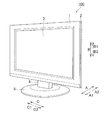
- FIG. 1 is a perspective view showing the overall structure of a liquid crystal display device according to a first embodiment of the present invention
- FIG. 2 is an exploded perspective view showing the structure of a liquid crystal module according to the first embodiment of the present invention
- FIG. 3 is an enlarged, exploded perspective view showing a part on a C2 side, of the liquid crystal module according to the first embodiment of the present invention
- FIG. 4 is a plan view showing the periphery of a folded section of the liquid crystal module according to the first embodiment of the present invention
- FIG. 5 is a plan view showing the periphery of a positioning member of the liquid crystal module according to the first embodiment of the present invention
- FIG. 6 is a sectional view of the liquid crystal module taken along the line 300 - 300 in FIG. 5 ;
- FIG. 7 is a perspective view showing the positioning member and an optical sheet of the liquid crystal module according to the first embodiment of the present invention.
- FIG. 8 is a sectional view showing a liquid crystal module of a liquid crystal display device according to a second embodiment of the present invention.
- the liquid crystal television set 100 is an example of the “display device” in the present invention.
- the liquid crystal television set 100 includes a front housing 1 arranged on the front side (A1 side), a rear housing 2 arranged on the rear side (A2 side), a liquid crystal module 3 arranged between the front housing 1 and the rear housing 2 , a support member 4 supporting the overall liquid crystal television set 100 , and a base member 5 supporting the support member 4 , as shown in FIG. 1 .
- the liquid crystal module 3 is an example of the “display module” in the present invention.
- the liquid crystal module 3 includes a rear frame 6 , a reflective sheet 7 , a positioning member 8 , a light guide plate 9 , a light source 10 , and an optical sheet 11 successively from the A2 side.
- the liquid crystal module 3 further includes a frame-shaped resin frame 12 , a liquid crystal panel 13 (liquid crystal cell), and a frame-shaped bezel 14 successively from the A2 side.
- the rear frame 6 is an example of the “frame” in the present invention
- the light source 10 is an example of the “light-emitting portion” in the present invention.
- the liquid crystal panel 13 is an example of the “display portion” and the “liquid crystal display portion” in the present invention.
- the rear frame 6 is made of metal (sheet metal) and provided in the form of a box having four sides.
- the rear frame 6 is formed to be capable of storing the reflective sheet 7 , the positioning member 8 , the light guide plate 9 , the light source 10 , and the optical sheet 11 inside.
- Seven engaging portions 6 a are formed on the side surface of the rear frame 6 on a B1 side.
- Two engaging holes 6 b are formed on the side surface of the rear frame 6 on a C1 side.
- two engaging holes 6 b are formed on the side surface of the rear frame 6 on a C2 side, similarly to the side surface on the C1 side.
- a notched hole 60 and a folded section 61 are formed in the bottom portion 6 c of the rear frame 6 in the vicinity of the side surface on the C2 side, as shown in FIG. 3 .
- This folded section 61 is formed by uprightly folding a part of the bottom portion 6 c from the C1 side toward the C2 side on the A1 side.
- the notched hole 60 is formed of a part of the bottom portion 6 c corresponding to the folded section 61 .
- the folded section 61 is formed on the C2 side of the notched hole 60 .
- the notched hole 60 is an example of the “hole” in the present invention.
- the notched section 60 is constituted by inner surfaces 60 a and 60 b linearly extending in a direction C on B1 and B2 sides, an inner surface 60 c linearly extending in a direction B on the C1 side, and an inner surface 60 d formed in the boundary with the notched section 61 on the C2 side.
- the inner surfaces 60 a and 60 c are arcuately connected to each other on the B1 side while the inner surfaces 60 b and 60 c are arcuately connected to each other on the B2 side.
- the folded section 61 formed of the part of the bottom portion 6 c corresponding to the notched hole 60 has a shape corresponding to the hole shape of the notched hole 60 .
- the folded section 61 is in the form of a flat plate so extending as to be raised in a direction A.
- Side surfaces 61 a and 61 b corresponding to the inner surfaces 60 a and 60 b of the notched hole 60 are so formed on the B1 and B2 sides of the folded section 61 as to extend in the direction A.
- An upper surface 61 c corresponding to the inner surface 60 c of the notched hole 60 is so formed on the A1 side of the folded section 61 as to extend in the direction B.
- the side surface 61 a and the upper surface 61 c are connected by a curved (arcuate) chamfer on the B1 side while the side surface 61 b and the upper surface 61 c are connected by a curved (arcuate) chamfer on the B2 side.
- the side surface 61 d of the folded section 61 on the C2 side, corresponding to the surface of the bottom portion 6 c on the A1 side and the side surface 61 e of the folded section 61 on the C1 side, corresponding to the surface of the bottom portion 6 c on the A2 side are planarized.
- the folded section 61 has a height H 1 in the direction A, a length L 1 in the direction B, and a thickness t 1 (see FIG. 4 ) in the direction C.
- the reflective sheet 7 is in the form of a plate and arranged on the surface of the bottom portion 6 c of the rear frame 6 on the A1 side, as shown in FIG. 2 .
- This reflective sheet 7 has a function of reflecting light travelling to the A2 side toward the A1 side.
- a concave positioning portion 70 having an opening on the C2 side is formed in the vicinity of the side surface of the reflective sheet 7 on the C2 side.
- This positioning portion 70 is formed with planarized inner surfaces 70 a and 70 b on the B1 and B2 sides and a planarized inner surface 70 c on the C1 side, as shown in FIG. 3 .
- the inner surface 70 a on the B1 side and the inner surface 70 c on the C1 side are arcuately connected to each other while the inner surface 70 b on the B2 side and the inner surface 70 c on the C1 side are arcuately connected to each other.
- the positioning portion 70 is an example of the “third positioning portion” in the present invention.
- the positioning portion 70 is so formed that a length L 2 from the inner surface 70 c on the C1 side to the opening on the C2 side is larger than the thickness t 1 of the folded section 61 while an interval L 3 between the inner surfaces 70 a and 70 b is larger than the length L 1 of the folded section 61 .
- the concave positioning portion 70 is arranged on the folded section 61 of the rear frame 6 from the C2 side of the positioning portion 70 , whereby the inner surfaces 70 a and 70 b of the positioning portion 70 are positioned by the side surfaces 61 a and 61 b of the folded section 61 , respectively while the inner surface 70 c of the positioning portion 70 is positioned by the side surface 61 e of the folded section 61 . Consequently, the reflective sheet 7 is positioned with respect to the rear frame 6 .
- the reflective sheet 7 is so formed as to cover a part of the notched hole 60 on the C1 side from the A1 side (see FIG. 3 ) in a state where the same is positioned with respect to the rear frame 6 . At this time, a clearance D is formed between the reflective sheet 7 and the folded section 61 .
- the side surface of the reflective sheet 7 on the B1 side is formed with seven protrusion portions 7 b at positions corresponding to the seven engaging portions 6 a of the rear frame 6 .
- the reflective sheet 7 can reflect light also at the seven engaging portions 6 a of the rear frame 6 toward the A1 side.
- the positioning member 8 has a substantially rectangular parallelepiped shape, as shown in FIG. 3 , and is made of a white resin member capable of reflecting light.
- the positioning member 8 has a length L 4 in the direction B and a width (thickness) t 2 in the direction C, as shown in FIG. 5 .
- the positioning member 8 is so arranged as to cover the folded section 61 in a state where the reflective sheet 7 is arranged on the bottom portion 6 c of the rear frame 6 .
- the bottom surface (surface on the A2 side) of the positioning member 8 is formed with a concave groove portion 80 having an opening on the A2 side, as shown in FIG. 3 .
- This groove portion 80 is so formed on the C2 side of the positioning member 8 as to uniformly extend in the direction B from the side surface of the positioning member 8 on the B1 side to the side surface of the positioning member 8 on the B2 side, as shown in FIG. 5 .
- the groove portion 80 is an example of the “recess portion” in the present invention.
- the depth in the direction A, of the side surface of the groove portion 80 on the C1 side is larger than the depth in the direction A, of the side surface of the groove portion 80 on the C2 side. Furthermore, the depth in the direction A, of the side surface of the groove portion 80 on the C1 side is larger than the height H 1 of the folded section 61 while the length L 4 of the positioning member 8 in the direction B is larger than the length L 1 of the folded section 61 . Consequently, the groove portion 80 of the positioning member 8 is so formed as to be fitted onto the folded section 61 and cover the overall folded section 60 from the A1 side (see FIG. 3 ) in a state fitted onto the folded section 61 , as shown in FIG. 5 .
- the bottom surface (surface on the A2 side) of the positioning member 8 is formed with a protrusion portion 81 protruding downward, formed on the C1 side of the groove portion 80 , a bottom surface portion 82 extending to the C1 side, formed on the A1 side relative to the protrusion portion 81 , and a bottom surface portion 83 formed on the C2 side of the groove portion 80 .
- the protrusion portion 81 is an example of the “portion” in the present invention.
- the protrusion portion 81 is inserted into between the reflective sheet 7 and the folded section 61 to close the clearance D between the reflective sheet 7 and the folded section 61 in a state where the groove portion 80 of the positioning member 8 is fitted onto the folded section 61 of the rear frame 6 , as shown in FIG. 6 .
- the protrusion portion 81 of the positioning member 8 is so formed as to cover a part of the notched hole 60 on the C2 side from the A1 side in the periphery of the folded section 61 of the rear frame 6 .
- the overall notched hole 60 of the rear frame 6 is covered with the reflective sheet 7 and the protrusion portion 81 of the positioning member 8 .
- the lower end of the protrusion portion 81 on the A2 side is located on the A2 side relative to the surface of the bottom portion 6 c of the rear frame 6 on the A2 side.
- the bottom surface portion 82 on the C1 side of the positioning member 8 is so formed as to come into contact with the upper surface 7 a of the reflective sheet 7 on the A1 side in the periphery of the positioning member 8 in the state where the groove portion 80 of the positioning member 8 is fitted onto the folded section 61 .
- the bottom surface portion 83 on the C2 side is so formed as to come into contact with the surface of the bottom portion 6 c of the rear frame 6 on the A1 side, located on the C2 side of the folded section 61 .
- the lower surface of the resin frame 12 is arranged on the planarized upper surface (surface on the A1 side) 84 of the positioning member 8 .
- side surfaces 85 a and 85 b on the A1 side of the positioning member 8 as well as on the B1 and B2 sides of the positioning member 8 are so planarized as to extend in the direction C, as shown in FIG. 5 .
- side surfaces 85 c and 85 d on the C2 and C1 sides of the positioning member 8 are so planarized as to extend in the direction B.
- a curved (arcuate) chamfer 85 e is formed between the side surface 85 a on the B1 side and the side surface 85 d on the C1 side while a curved (arcuate) chamfer 85 f is formed between the side surface 85 b on the B2 side and the side surface 85 d on the C1 side.
- a positioning portion 85 having a shape corresponding to the concave shapes of a positioning portion 90 of the light guide plate 9 and a positioning portion 110 of the optical sheet 11 described later is constituted by the side surfaces 85 a , 85 b , and 85 d and the chamfers 85 e and 85 f .
- the positioning portion 85 is arranged in a position to position the positioning portion 90 of the light guide plate 9 and the positioning portion 110 of the optical sheet 11 in the state where the groove portion 80 of the positioning member 8 is fitted onto the folded section 61 of the rear frame 6 .
- the positioning portion 85 is an example of the “second positioning portion” in the present invention, and the side surfaces 85 a , 85 b , and 85 d are examples of the “first side surface”, the “second side surface”, and the “third side surface” in the present invention, respectively.
- the directions C and B are examples of the “first direction” and the “second direction” in the present invention, respectively.
- the light guide plate 9 is made of PC (polycarbonate) resin in the form of a flat plate and arranged on the upper surface 7 a of the reflective sheet 7 on the A1 side, as shown in FIG. 2 .
- the light source 10 having a plurality of LEDs 10 a arranged along the direction C at constant intervals is arranged in a position corresponding to the side surface of the light guide plate 9 on the B2 side.
- This light guide plate 9 has a function of guiding light emitted to the B1 side from the plurality of LEDs 10 a to the A1 side.
- the concave positioning portion 90 having an opening on the C2 side is formed in the vicinity of the side surface of the light guide plate 9 on the C2 side, as shown in FIG. 5 .
- This positioning portion 90 is formed with planarized inner surfaces 90 a and 90 b extending in the direction C on the B1 and B2 sides and a planarized inner surface 90 c extending in the direction B on the C1 side.
- An arcuate connection portion 90 d is formed between the inner surface 90 a on the B1 side and the inner surface 90 c on the C1 side while an arcuate connection portion 90 e is formed between the inner surface 90 b on the B2 side and the inner surface 90 c on the C1 side.
- the positioning portion 90 is so formed that a length L 5 from the inner surface 90 c on the C1 side to the opening on the C2 side is larger than the width (thickness) t 2 of the positioning member 8 while an interval L 6 between the inner surfaces 90 a and 90 b is larger than the length L 4 of the positioning member 8 .
- the positioning portion 90 is an example of the “first positioning portion” in the present invention.
- the concave positioning portion 90 is arranged on the positioning member 8 from the C2 side of the positioning portion 90 , whereby the planarized inner surfaces 90 a and 90 b of the positioning portion 90 are positioned by the planarized side surfaces 85 a and 85 b of the positioning member 8 , respectively while the planarized inner surface 90 c of the positioning portion 90 is positioned by the planarized side surface 85 d of the positioning member 8 .
- the connection portions 90 d and 90 e of the positioning portion 90 are positioned by the chamfers 85 e and 85 f of the positioning member 8 , respectively. Consequently, the concave positioning portion 90 of the light guide plate 9 made of resin is positioned with respect to the positioning portion 85 of the positioning member 8 made of resin.
- the inner surfaces 90 a , 90 b , and 90 c are examples of the “first inner surface”, the “second inner surface”, and the “third inner surface” in the present invention, respectively.
- the optical sheet 11 is made of resin in the form of a flat plate and arranged on the upper surface 9 a of the light guide plate 9 on the A1 side, as shown in FIG. 2 .
- This optical sheet 11 is made of a diffusion sheet diffusing light or a prism sheet guiding light to the A1 side.
- the concave positioning portion 110 having a shape similar to that of the positioning portion 90 of the light guide plate 9 in plan view (as viewed from the A1 side (see FIG. 3 )) is formed in the vicinity of the side surface of the optical sheet 11 on the C2 side.
- the positioning portion 110 is formed with planarized inner surfaces 110 a and 110 b on the B1 and B2 sides and a planarized inner surface 110 c on the C1 side.
- An arcuate connection portion 110 d is formed between the inner surface 110 a on the B1 side and the inner surface 110 c on the C1 side while an arcuate connection portion 110 e is formed between the inner surface 110 b on the B2 side and the inner surface 110 c on the C1 side.
- the positioning portion 110 is so formed that a length L 5 from the inner surface 110 c on the C1 side to the opening on the C2 side is larger than the width (thickness) t 2 of the positioning member 8 while an interval L 6 between the inner surfaces 110 a and 110 b is larger than the length L 4 of the positioning member 8 .
- the positioning portion 110 is an example of the “fourth positioning portion” in the present invention.
- the concave positioning portion 110 is arranged on the positioning member 8 from the C2 side of the positioning portion 110 , whereby the planarized inner surfaces 110 a and 110 b of the positioning portion 110 are positioned by the planarized side surfaces 85 a and 85 b of the positioning member 8 , respectively while the planarized inner surface 110 c of the positioning portion 110 is positioned by the planarized side surface 85 d of the positioning member 8 .
- the connection portions 110 d and 110 e of the positioning portion 110 are positioned by the chamfers 85 e and 85 f of the positioning member 8 , respectively. Consequently, the optical sheet 11 made of resin is positioned with respect to the positioning portion 85 of the positioning member 8 made of resin.
- the position of the upper surface 84 of the positioning member 8 in the direction A is located on the A1 side relative to the position of the upper surface (surface on the A1 side) 11 a of the optical sheet 11 in the direction A, whereby the protrusion height of the upper surface 84 of the positioning member 8 is higher than the protrusion height of the upper surface 11 a of the optical sheet 11 .
- a clearance E is formed between the positioning portion 90 of the light guide plate 9 as well as the positioning portion 110 of the optical sheet 11 and the positioning portion 85 of the positioning member 8 .
- the clearance E is surrounded by the reflective sheet 7 , the positioning member 8 , and the resin frame 12 so that leakage of light from the clearance E to the outside can be inhibited.
- the resin frame 12 has a wall portion 12 a arranged between the side surface of the rear frame 6 on the C1 side and the side surface 85 c of the positioning member 8 and a support portion 12 b extending from the A1 side of the wall portion 12 a to the C1 side, as shown in FIG. 6 .
- This support portion 12 b supports the liquid crystal panel 13 from the A2 side.
- seven engaging protrusion portions 12 c fitted into the seven engaging portions 6 a of the rear frame 6 are formed on the side surface of the resin frame 12 on the B1 side.
- the liquid crystal panel 13 has a function of displaying an image on the A1 side on the basis of light emitted from the light source 10 .
- Engaging portions 14 a corresponding to the two engaging holes 6 b of the rear frame 6 are formed on the side surface of the frame-shaped bezel 14 on the C1 side.
- unshown engaging portions corresponding to the engaging holes 6 b of the rear frame 6 are formed on the side surface of the frame-shaped bezel 14 on the C2 side, similarly to the side surface on the C1 side.
- the engaging portions 14 a and the unshown engaging portions engage with the four engaging holes 6 b of the rear frame 6 , whereby the bezel 14 is fixed onto the rear frame 6 .
- the concave positioning portion 90 of the light guide plate 9 made of resin is positioned with respect to the positioning portion 85 of the positioning member 8 made of resin, whereby the light guide plate 9 made of resin can be positioned by the positioning member 8 made of resin.
- formation of a defect such as wear or breakage on the light guide plate 9 can be inhibited dissimilarly to a case where the light guide plate 9 made of resin is positioned by the folded section 61 formed by partially uprightly folding the rear frame 6 made of metal.
- the light guide plate 9 is so arranged that the concave positioning portion 90 of the light guide plate 9 corresponds to the positioning portion 85 of the positioning member 8 , whereby the light guide plate 9 can be easily positioned.
- the protrusion portion 81 of the positioning member 8 is arranged between the reflective sheet 7 and the folded section 61 to close the clearance D between the reflective sheet 7 and the folded section 61 in the state where the groove portion 80 is fitted onto the folded section 61 of the rear frame 6 , whereby the positioning member 8 can inhibit leakage of light inside the liquid crystal module 3 from the notched hole 60 to the outside. Furthermore, the protrusion portion 81 of the positioning member 8 can inhibit leakage of light from the notched hole 60 formed when the folded section 61 is formed through the clearance D between the folded section 61 and the reflective sheet 7 .
- the side surfaces 85 a and 85 b of the positioning portion 85 of the positioning member 8 are so planarized as to extend in the direction C
- the side surface 85 d of the positioning portion 85 is so planarized as to extend in the direction B
- the inner surfaces 90 a and 90 b of the positioning portion 90 of the light guide plate 9 are so planarized as to extend in the direction C
- the inner surface 90 c of the positioning portion 90 is so planarized as to extend in the direction B.
- the inner surfaces 90 a and 90 b of the positioning portion 90 are positioned by the side surfaces 85 a and 85 b of the positioning portion 85 , respectively while the inner surface 90 c of the positioning portion 90 is positioned by the side surface 85 d of the positioning portion 85 .
- the side surfaces 85 a and 85 b of the positioning portion 85 can regulate movement of the positioning portion 90 in the direction B while the side surface 85 d of the positioning portion 85 can regulate movement of the positioning portion 90 in either one direction (direction C 2 ) of two directions included in the direction C. Consequently, the light guide plate 9 can be reliably positioned.
- the folded section 61 formed by uprightly folding the part of the bottom portion 6 c corresponding to the notched hole 60 from the C1 side toward the C2 side on the A1 side is formed in the rear frame 6
- the groove portion 80 fitted onto the folded section 61 is formed in the positioning member 8
- the positioning portion 85 is arranged in the position to position the positioning portion 90 of the light guide plate 9 and the positioning portion 110 of the optical sheet 11 in the state where the groove portion 80 of the positioning member 8 is fitted onto the folded section 61 of the rear frame 6 .
- the position of the positioning portion 85 of the positioning member 8 can be easily defined by the folded section 61 of the rear frame 6 .
- the position of the positioning portion 85 of the positioning member 8 is defined by the folded section 61 of the rear frame 6 , whereby the position of the light guide plate 9 positioned by the positioning portion 85 and the position of the rear frame 6 can be easily associated with each other.
- the bottom surface portion 82 on the C1 side of the positioning member 8 is so formed as to come into contact with the upper surface 7 a of the reflective sheet 7 on the A1 side in the periphery of the positioning member 8 in the state where the groove portion 80 of the positioning member 8 is fitted onto the folded section 61 .
- the reflective sheet 7 is held between the rear frame 6 and the positioning member 8 , and hence positional deviation of the reflective sheet 7 can be inhibited.
- the inner surfaces 70 a and 70 b of the positioning portion 70 of the reflective sheet 7 are positioned by the side surfaces 61 a and 61 b of the folded section 61 , respectively while the inner surface 70 c of the positioning portion 70 is positioned by the side surface 61 e of the folded section 61 .
- the reflective sheet 7 can be easily positioned by the folded section 61 of the rear frame 6 .
- the protrusion portion 81 is inserted into between the reflective sheet 7 and the folded section 61 to close the clearance D between the reflective sheet 7 and the folded section 61 .
- the clearance D between the reflective sheet 7 and the folded section 61 can be closed by the protrusion portion 81 , and hence the leakage of light from the notched hole 60 formed when the folded section 61 is formed can be further inhibited.
- the overall notched hole 60 of the rear frame 6 is covered with the reflective sheet 7 and the protrusion portion 81 of the positioning member 8 , whereby leakage of light from the notched hole 60 of the rear frame 6 can be reliably inhibited.
- the notched hole 60 and the folded section 61 are formed in the vicinity of the side surface of the bottom portion 6 c of the rear frame 6 on the C2 side, and the folded section 61 is formed by folding the part of the bottom portion 6 c from the C1 side toward the C2 side on the A1 side so that the same is formed on the C2 side of the notched hole 60 .
- the folded section 61 of the rear frame 6 can be brought closer to the side surface, and hence a wider region where the liquid crystal panel 13 , the light source 10 , and the light guide plate 9 are arranged can be secured.
- the planarized inner surfaces 110 a and 110 b of the positioning portion 110 of the optical sheet 11 are positioned by the planarized side surfaces 85 a and 85 b of the positioning member 8 , respectively while the planarized inner surface 110 c of the positioning portion 110 is positioned by the planarized side surface 85 d of the positioning member 8 .
- the optical sheet 11 can be easily positioned by the positioning portion 85 of the positioning member 8 .
- the protrusion height of the upper surface 84 of the positioning member 8 is higher than the protrusion height of the upper surface 11 a of the optical sheet 11 .
- the overall positioning portion 90 of the light guide plate 9 and the overall positioning portion 110 of the optical sheet 11 can be brought into contact with the positioning portion 85 of the positioning member 8 .
- the light guide plate 9 and the optical sheet 11 can be reliably positioned on the positioning portion 85 of the positioning member 8 .
- the positioning member 8 is made of the white resin member capable of reflecting light. According to this structure, the positioning member 8 can also reflect light, and hence light emitted from the light source 10 can be effectively utilized.
- a folded section 261 is formed on a C1 side of the notched hole 260 dissimilarly to the aforementioned first embodiment.
- the notched hole 260 is an example of the “hole” in the present invention.
- the notched hole 260 and the folded section 261 are formed in the vicinity of the side surface of a bottom portion 6 c of a rear frame 206 on a C2 side.
- This folded section 261 is provided in the form of a flat plate so extending as to be raised in a direction A by uprightly folding a part of the bottom portion 6 c from the C2 side toward the C1 side on an A1 side.
- the notched hole 260 is formed of a part of the bottom portion 6 c corresponding to the folded section 261 .
- the folded section 261 is formed on the C1 side of the notched hole 260 .
- a reflective sheet 207 arranged on the C1 side of the folded section 261 is so formed as not to cover the notched hole 260 in a state where the reflective sheet 207 is positioned with respect to the rear frame 206 , dissimilarly to the aforementioned first embodiment. At this time, a clearance D is formed between the reflective sheet 207 and the folded section 261 .
- a groove portion 280 fitted onto the folded section 261 , a bottom surface portion 281 formed on the C1 side of the groove portion 280 , and a bottom surface portion 282 formed on the C2 side of the groove portion 280 are formed in the bottom surface (surface on an A2 side) of a positioning member 208 .
- the depth in the direction A, of the side surface of the groove portion 280 on the C2 side is larger than the depth in the direction A, of the side surface of the groove portion 280 on the C1 side.
- the groove portion 280 is an example of the “recess portion” in the present invention.
- the bottom surface portion 281 on the C1 side of the positioning member 208 is so formed as to come into contact with the upper surface 7 a of the reflective sheet 207 on the A1 side in the periphery of the folded section 261 in a state where the groove portion 280 is fitted onto the folded section 261 .
- the bottom surface portion 281 on the C1 side is also located on the A1 side of the clearance D between the folded section 261 and the reflective sheet 207 .
- the positioning member 208 can inhibit leakage of light from the clearance D between the folded section 261 and the reflective sheet 207 to the outside.
- the lower portion on the A2 side, of the bottom surface portion 282 of the positioning member 208 on the C2 side is arranged in the notched hole 260 while the lower end of the bottom surface portion 282 on the A2 side is located on the A2 side relative to the surface of the bottom portion 6 c of the rear frame 206 on the A2 side.
- the bottom surface portion 282 of the positioning member 208 is so formed as to cover a part of the notched hole 260 on the C1 side from the A1 side in the periphery of the folded section 261 of the rear frame 206 .
- a positioning portion 283 formed of a side surface of the positioning member 208 is so formed as to be capable of positioning a positioning portion 90 of a light guide plate 9 and a positioning portion 110 of an optical sheet 11 in the state where the groove portion 280 of the positioning member 208 is fitted onto the folded section 261 , similarly to the aforementioned first embodiment.
- the positioning portion 283 is an example of the “second positioning portion” in the present invention.
- the remaining structure of the second embodiment of the present invention is similar to that of the aforementioned first embodiment.
- the positioning portion 283 formed of the side surface of the positioning member 208 made of resin is so formed as to be capable of positioning the concave positioning portion 90 of the light guide plate 9 made of resin.
- the light guide plate 9 made of resin can be positioned by the positioning member 208 made of resin, and hence formation of a defect such as wear or breakage on the light guide plate 9 can be inhibited.
- the bottom surface portion 282 of the positioning member 208 is so formed as to cover the part of the notched hole 260 on the C2 side from the A1 side in the periphery of the folded section 261 of the rear frame 206 , whereby the positioning member 208 made of resin can inhibit leakage of light inside the liquid crystal module 203 from the notched hole 260 to the outside.
- the folded section 261 is formed by folding the part of the bottom portion 6 c from the C2 side toward the C1 side on the A1 side so that the same is formed on the C1 side of the notched hole 260 .
- the folded section 261 so extending as to be raised in the direction A can be arranged between the light guide plate 9 and the notched hole 260 , and hence the folded section 261 can inhibit light from the light guide plate 9 from reaching the notched hole 260 .
- leakage of light from the notched hole 260 can be further inhibited.
- the remaining effects of the second embodiment are similar to those of the aforementioned first embodiment.
- the present invention is not restricted to this.
- the groove portion of the positioning member may not be fitted onto the folded section of the rear frame so far as the positioning portion of the positioning member can position the positioning portion of the light guide plate and the positioning portion of the optical sheet.
- the liquid crystal television set may alternatively be so formed that the positioning portion of the light guide plate and the positioning portion of the optical sheet can be positioned by the positioning portion of the positioning member in a state where the positioning member comes into contact with a side surface of a hole for positioning.
- each of the positioning portion 90 of the light guide plate 9 and the positioning portion 110 of the optical sheet 11 is formed in a concave shape in each of the aforementioned first and second embodiments, the present invention is not restricted to this.
- each of the positioning portion of the light guide plate and the positioning portion of the optical sheet may be formed in a convex shape, and the side surface of the positioning member may be formed in a shape corresponding to the convex shape, for example.
- the positioning portion of the light guide plate may be formed in a concave shape
- the positioning portion of the optical sheet may be formed in a convex shape
- a portion in a shape corresponding to the concave shape and a portion in a shape corresponding to the convex shape may be formed in the side surface of the positioning member.
- Each of the shapes of the positioning portions of the light guide plate and the optical sheet is not restricted to a particular shape so far as the shape enables positioning.
- the positioning member 8 or 208 is so formed as to position not only the light guide plate 9 but also the optical sheet 11 in each of the aforementioned first and second embodiments, the present invention is not restricted to this.
- the positioning member may alternatively be so formed as to be capable of positioning at least the light guide plate. Thus, the positioning member can be reduced in size.
- the protrusion height of upper surface 84 of the positioning member 8 is higher than the protrusion height of the upper surface 11 a of the optical sheet 11 in the aforementioned first embodiment, the present invention is not restricted to this.
- the protrusion height of the upper surface 84 of the positioning member 8 may alternatively be equal to the protrusion height of the upper surface 11 a of the optical sheet 11 .
- the portions (the notched hole 60 or 260 and the folded section 61 or 261 of the rear frame 6 or 206 , the positioning portion 70 of the reflective sheet 7 or 207 , the positioning portion 85 or 283 of the positioning member 8 or 208 , the positioning portion 90 of the light guide plate 9 , and the positioning portion 110 of the optical sheet 11 ) of the liquid crystal module 3 or 203 contributing to positioning are provided at a position in the vicinity of the side surface of the liquid crystal module 3 or 203 on the C2 side in each of the aforementioned first and second embodiments, the present invention is not restricted to this.
- the portions of the liquid crystal module contributing to positioning may alternatively be provided at another position other than the vicinity of the side surface of the liquid crystal module on the C2 side.
- the portions of the liquid crystal module contributing to positioning may alternatively be provided at a plurality of positions.
- the rear frame, the reflective sheet, the light guide plate, and the optical sheet can be more reliably positioned.
- the recess portion in the present invention is formed of the groove portion 80 or 280 uniformly extending in the direction B from the side surface of the positioning member 8 or 208 on the B1 side to the side surface of the positioning member 8 or 208 on the B2 side in each of the aforementioned first and second embodiments, the present invention is not restricted to this.
- the recess portion may simply be capable of being fitted onto the folded section.
- the recess portion may be so formed as to uniformly extend in the direction B from the vicinity of the side surface on the B1 side to the vicinity of the side surface on the B2 side, not extend from the side surface on the B1 side to the side surface on the B1 side.
- the positioning member 8 or 208 is made of the white resin member capable of reflecting light in each of the aforementioned first and second embodiments, the present invention is not restricted to this. In the present invention, the positioning member may simply be at least a resin member.
- the light guide plate 9 is made of PC (polycarbonate) resin in each of the aforementioned first and second embodiments, the present invention is not restricted to this.
- the light guide plate 9 may alternatively be made of another resin material such as ABS (acrylonitrile butadiene styrene) resin, acrylic resin, or PET (polyethylene terephthalate) resin.
- the “display device” in the present invention is applied to the liquid crystal television set 100 in each of the aforementioned first and second embodiments, the present invention is not restricted to this.
- the “display device” in the present invention may alternatively be applied to a liquid crystal display monitor loaded into a car navigation system, an information display monitor (liquid crystal display monitor) loaded into a train, a bus, a ship, or an airplane, or the like.
Landscapes
- Physics & Mathematics (AREA)
- General Physics & Mathematics (AREA)
- Chemical & Material Sciences (AREA)
- Crystallography & Structural Chemistry (AREA)
- Engineering & Computer Science (AREA)
- Optics & Photonics (AREA)
- Nonlinear Science (AREA)
- Computer Hardware Design (AREA)
- Theoretical Computer Science (AREA)
- Mathematical Physics (AREA)
- Planar Illumination Modules (AREA)
- Liquid Crystal (AREA)
Abstract
Description
- 1. Field of the Invention
- The present invention relates to a display module, a display device, and a liquid crystal television set, and more particularly, it relates to a display module, a display device, and a liquid crystal television set each including a light guide plate made of resin and a frame made of metal.
- 2. Description of the Background Art
- A display module including a light guide plate made of resin and a frame made of metal is known in general, as disclosed in Japanese Patent Laying-Open No. 2003-279934, for example.
- The aforementioned Japanese Patent Laying-Open No. 2003-279934 discloses an image display device including a displaying unit, a backlight unit having a light guide plate to apply light to the displaying unit, and a lower frame made of metal supporting the backlight unit. The light guide plate of the backlight unit in the image display device according to the aforementioned Japanese Patent Laying-Open No. 2003-279934 is formed with concave notches. A pair of bent portions extending upward are so formed on the lower frame as to correspond to the inner surfaces of the concave notches of the light guide plate, opposed to each other. In the image display device according to the aforementioned Japanese Patent Laying-Open No. 2003-279934, the backlight unit is so arranged on the lower frame that the concave notches of the light guide plate of the backlight unit correspond to the pair of bent portions of the lower frame, whereby the backlight unit is positioned with respect to the lower frame.
- In the image display device according to the aforementioned Japanese Patent Laying-Open No. 2003-279934, however, the concave notches of the light guide plate and the bent portions of the lower frame made of metal may come into contact with each other during assembling, transportation, or the like of the image display device in a state where the backlight unit is arranged on the lower frame. In this case, the light guide plate is generally made of resin that is more fragile than metal, whereby defects such as weak or breakage are disadvantageously easily formed on contact portions of the concave notches (positioning portions) of the light guide plate with the bent portions.
- The present invention has been proposed in order to solve the aforementioned problem, and an object of the present invention is to provide a display module, a display device, and a liquid crystal television set capable of inhibiting formation of a defect such as weak or breakage on a light guide plate due to contact of a positioning portion of the light guide plate made of resin with a frame made of metal.
- A display module according to a first aspect of the present invention includes a display portion, a light-emitting portion to apply light to the display portion, a light guide plate made of resin to guide the light from the light-emitting portion to the display portion, including a first positioning portion, a frame made of metal in which the light guide plate is arranged inside, including a hole, and a positioning member made of resin, including a second positioning portion so formed as to be capable of positioning the first positioning portion of the light guide plate in a state where the positioning member is so arranged as to cover the hole of the frame.
- As hereinabove described, the display module according to the first aspect of the present invention includes the light guide plate made of resin, including the first positioning portion and the positioning member made of resin, including the second positioning portion so formed as to be capable of positioning the first positioning portion of the light guide plate, whereby the light guide plate made of resin can be positioned by the positioning member made of resin. Thus, formation of a defect such as wear or breakage on the light guide plate can be inhibited dissimilarly to a case where the light guide plate made of resin is positioned by a positioning portion formed by partially uprightly folding the frame made of metal. Furthermore, the positioning member made of resin is so arranged as to cover the hole of the frame, whereby the positioning member can inhibit leakage of light inside the display module from the hole to the outside.
- In the aforementioned display module according to the first aspect, the first positioning portion of the light guide plate preferably has a concave shape, and the second positioning portion of the positioning member preferably has a shape corresponding to the concave shape of the first positioning portion. According to this structure, the light guide plate is so arranged that the concave first positioning portion of the light guide plate corresponds to the second positioning portion of the positioning member, whereby the light guide plate can be easily positioned.
- In this case, the first positioning portion having the concave shape preferably extends in a first direction and has first and second inner surfaces opposed to each other and a third inner surface extending in a second direction substantially orthogonal to the first direction, and the second positioning portion preferably extends in the first direction and has first and second side surfaces positioning the first and second inner surfaces, respectively and a third side surface extending in the second direction, positioning the third inner surface. According to this structure, the first and second side surfaces of the second positioning portion can regulate movement of the first positioning portion in the second direction while the third side surface of the second positioning portion can regulate movement of the first positioning portion in either one direction of two directions included in the first direction. Consequently, the light guide plate can be reliably positioned.
- In the aforementioned display module according to the first aspect, the frame preferably further includes a folded section formed when the hole is formed by partially uprightly folding the frame, the positioning member preferably further includes a recess portion fitted onto the folded section, and a position of the second positioning portion of the positioning member is preferably defined in a state where the recess portion is fitted onto the folded section. According to this structure, the position of the second positioning portion of the positioning member can be easily defined by the folded section of the frame.
- The aforementioned display module including the frame including the folded section preferably further includes a reflective sheet arranged between the light guide plate and the frame, and the positioning member is preferably arranged on a surface of the reflective sheet closer to the light guide plate at least in a periphery of the folded section. According to this structure, the reflective sheet is held between the frame and the positioning member, and hence positional deviation of the reflective sheet can be inhibited.
- The aforementioned display module including the frame including the folded section preferably further includes a reflective sheet arranged between the light guide plate and the frame, including a third positioning portion so formed as to be capable of being positioned by the folded section. According to this structure, the reflective sheet can be easily positioned by the folded section of the frame.
- The aforementioned display module including the frame including the folded section preferably further includes a reflective sheet arranged between the light guide plate and the frame, and the positioning member preferably further includes a portion arranged between the folded section and the reflective sheet to close a clearance between the folded section and the reflective sheet. According to this structure, the portion of the positioning member arranged between the folded section and the reflective sheet can inhibit leakage of light from the hole formed when the folded section is formed through the clearance between the folded section and the reflective sheet.
- In the aforementioned display module including the positioning member including the portion to close the clearance, the portion of the positioning member preferably protrudes toward the frame and is preferably inserted into between the folded section and the reflective sheet to close the clearance between the folded section and the reflective sheet. According to this structure, the portion inserted into between the folded section and the reflective sheet can close the clearance between the folded section and the reflective sheet, and hence the leakage of light from the hole formed when the folded section is formed can be further inhibited.
- In the aforementioned display module including the positioning member including the portion to close the clearance, the hole of the frame is preferably covered with the reflective sheet and the portion of the positioning member. According to this structure, leakage of light from the hole of the frame can be reliably inhibited.
- In the aforementioned display module including the frame including the folded section, the folded section of the frame is preferably formed in a vicinity of a side surface of the frame. According to this structure, a wide region where the display portion, the light-emitting portion, and the light guide plate are arranged can be secured.
- In the aforementioned display module including the folded section formed in the vicinity of the side surface, the folded section is preferably formed toward the side surface of the frame so that the folded section is formed on a side of the side surface of the frame relative to the hole. According to this structure, the folded section of the frame can be brought closer to the side surface, and hence a wider region where the display portion, the light-emitting portion, and the light guide plate are arranged can be secured.
- In the aforementioned display module including the folded section formed in the vicinity of the side surface, the folded section is preferably formed toward a side opposite to the side surface of the frame so that the folded section is formed on the side opposite to the side surface of the frame relative to the hole. According to this structure, the folded section can be arranged between the light guide plate and the hole, and hence the folded section can inhibit light from the light guide plate from reaching the hole. Thus, leakage of light from the hole can be further inhibited.
- The aforementioned display module according to the first aspect preferably further includes an optical sheet including a fourth positioning portion so formed as to be capable of being positioned by the second positioning portion of the positioning member, arranged on a surface of the light guide plate closer to the display portion. According to this structure, the optical sheet can be easily positioned by the second positioning portion of the positioning member.
- In this case, a protrusion height of an end portion of the second positioning portion of the positioning member closer to the display portion is preferably at least a protrusion height of an end portion of the fourth positioning portion of the optical sheet closer to the display portion. According to this structure, the overall first positioning portion of the light guide plate and the overall fourth positioning portion of the optical sheet can be brought into contact with the second positioning portion of the positioning member. Thus, the light guide plate and the optical sheet can be reliably positioned on the second positioning portion of the positioning member.
- In the aforementioned display module according to the first aspect, the positioning member is preferably made of a white resin member capable of reflecting light. According to this structure, the positioning member can also reflect light, and hence light emitted from the light-emitting portion can be effectively utilized.
- A display device according to a second aspect of the present invention includes a display portion, a light-emitting portion to apply light to the display portion, a light guide plate made of resin to guide the light from the light-emitting portion to the display portion, including a first positioning portion, a frame made of metal in which the light guide plate is arranged inside, including a hole, and a positioning member made of resin, including a second positioning portion so formed as to be capable of positioning the first positioning portion of the light guide plate in a state where the positioning member is so arranged as to cover the hole of the frame.
- As hereinabove described, the display device according to the second aspect of the present invention includes the light guide plate made of resin, including the first positioning portion and the positioning member made of resin, including the second positioning portion so formed as to be capable of positioning the first positioning portion of the light guide plate, whereby the light guide plate made of resin can be positioned by the positioning member made of resin. Thus, formation of a defect such as wear or breakage on the light guide plate can be inhibited dissimilarly to a case where the light guide plate made of resin is positioned by a positioning portion formed by partially uprightly folding the frame made of metal. Furthermore, the positioning member made of resin is so arranged as to cover the hole of the frame, whereby the positioning member can inhibit leakage of light inside the display device from the hole to the outside.
- In the aforementioned display device according to the second aspect, the first positioning portion of the light guide plate preferably has a concave shape, and the second positioning portion of the positioning member preferably has a shape corresponding to the concave shape of the first positioning portion. According to this structure, the light guide plate is so arranged that the concave first positioning portion of the light guide plate corresponds to the second positioning portion of the positioning member, whereby the light guide plate can be easily positioned.
- In the aforementioned display device according to the second aspect, the frame preferably further includes a folded section formed when the hole is formed by partially uprightly folding the frame, the positioning member preferably further includes a recess portion fitted onto the folded section, and a position of the second positioning portion of the positioning member is preferably defined in a state where the recess portion is fitted onto the folded section. According to this structure, the position of the second positioning portion of the positioning member can be easily defined by the folded section of the frame.
- The aforementioned display device including the frame including the folded section preferably further includes a reflective sheet arranged between the light guide plate and the frame, and the positioning member is preferably arranged on a surface of the reflective sheet closer to the light guide plate at least in a periphery of the folded section. According to this structure, the reflective sheet is held between the frame and the positioning member, and hence positional deviation of the reflective sheet can be inhibited.
- A liquid crystal television set according to a third aspect of the present invention includes a liquid crystal display portion, a light-emitting portion to apply light to the liquid crystal display portion, a light guide plate made of resin to guide the light from the light-emitting portion to the liquid crystal display portion, including a first positioning portion, a frame made of metal in which the light guide plate is arranged inside, including a hole, and a positioning member made of resin, including a second positioning portion so formed as to be capable of positioning the first positioning portion of the light guide plate in a state where the positioning member is so arranged as to cover the hole of the frame.
- As hereinabove described, the liquid crystal television set according to the third aspect of the present invention includes the light guide plate made of resin, including the first positioning portion and the positioning member made of resin, including the second positioning portion so formed as to be capable of positioning the first positioning portion of the light guide plate, whereby the light guide plate made of resin can be positioned by the positioning member made of resin. Thus, formation of a defect such as wear or breakage on the light guide plate can be inhibited dissimilarly to a case where the light guide plate made of resin is positioned by a positioning portion formed by partially uprightly folding the frame made of metal. Furthermore, the positioning member made of resin is so arranged as to cover the hole of the frame, whereby the positioning member can inhibit leakage of light inside the liquid crystal television set from the hole to the outside.
- The foregoing and other objects, features, aspects and advantages of the present invention will become more apparent from the following detailed description of the present invention when taken in conjunction with the accompanying drawings.
-
FIG. 1 is a perspective view showing the overall structure of a liquid crystal display device according to a first embodiment of the present invention; -
FIG. 2 is an exploded perspective view showing the structure of a liquid crystal module according to the first embodiment of the present invention; -
FIG. 3 is an enlarged, exploded perspective view showing a part on a C2 side, of the liquid crystal module according to the first embodiment of the present invention; -
FIG. 4 is a plan view showing the periphery of a folded section of the liquid crystal module according to the first embodiment of the present invention; -
FIG. 5 is a plan view showing the periphery of a positioning member of the liquid crystal module according to the first embodiment of the present invention; -
FIG. 6 is a sectional view of the liquid crystal module taken along the line 300-300 inFIG. 5 ; -
FIG. 7 is a perspective view showing the positioning member and an optical sheet of the liquid crystal module according to the first embodiment of the present invention; and -
FIG. 8 is a sectional view showing a liquid crystal module of a liquid crystal display device according to a second embodiment of the present invention. - Embodiments of the present invention are now described with reference to the drawings.
- First, the structure of a liquid
crystal television set 100 according to a first embodiment of the present invention is described with reference toFIGS. 1 to 7 . The liquidcrystal television set 100 is an example of the “display device” in the present invention. - The liquid
crystal television set 100 according to the first embodiment of the present invention includes a front housing 1 arranged on the front side (A1 side), arear housing 2 arranged on the rear side (A2 side), aliquid crystal module 3 arranged between the front housing 1 and therear housing 2, asupport member 4 supporting the overall liquidcrystal television set 100, and abase member 5 supporting thesupport member 4, as shown inFIG. 1 . Theliquid crystal module 3 is an example of the “display module” in the present invention. - As shown in
FIG. 2 , theliquid crystal module 3 includes arear frame 6, areflective sheet 7, apositioning member 8, alight guide plate 9, alight source 10, and anoptical sheet 11 successively from the A2 side. Theliquid crystal module 3 further includes a frame-shapedresin frame 12, a liquid crystal panel 13 (liquid crystal cell), and a frame-shapedbezel 14 successively from the A2 side. Therear frame 6 is an example of the “frame” in the present invention, and thelight source 10 is an example of the “light-emitting portion” in the present invention. Theliquid crystal panel 13 is an example of the “display portion” and the “liquid crystal display portion” in the present invention. - The
rear frame 6 is made of metal (sheet metal) and provided in the form of a box having four sides. Therear frame 6 is formed to be capable of storing thereflective sheet 7, the positioningmember 8, thelight guide plate 9, thelight source 10, and theoptical sheet 11 inside. Sevenengaging portions 6 a are formed on the side surface of therear frame 6 on a B1 side. Two engagingholes 6 b are formed on the side surface of therear frame 6 on a C1 side. Furthermore, two engagingholes 6 b are formed on the side surface of therear frame 6 on a C2 side, similarly to the side surface on the C1 side. - According to the first embodiment, a notched
hole 60 and a foldedsection 61 are formed in thebottom portion 6 c of therear frame 6 in the vicinity of the side surface on the C2 side, as shown inFIG. 3 . This foldedsection 61 is formed by uprightly folding a part of thebottom portion 6 c from the C1 side toward the C2 side on the A1 side. The notchedhole 60 is formed of a part of thebottom portion 6 c corresponding to the foldedsection 61. In other words, the foldedsection 61 is formed on the C2 side of the notchedhole 60. The notchedhole 60 is an example of the “hole” in the present invention. - The notched
section 60 is constituted byinner surfaces inner surface 60 c linearly extending in a direction B on the C1 side, and aninner surface 60 d formed in the boundary with the notchedsection 61 on the C2 side. Theinner surfaces inner surfaces - The folded
section 61 formed of the part of thebottom portion 6 c corresponding to the notchedhole 60 has a shape corresponding to the hole shape of the notchedhole 60. Specifically, the foldedsection 61 is in the form of a flat plate so extending as to be raised in a direction A. Side surfaces 61 a and 61 b corresponding to theinner surfaces hole 60 are so formed on the B1 and B2 sides of the foldedsection 61 as to extend in the direction A. Anupper surface 61 c corresponding to theinner surface 60 c of the notchedhole 60 is so formed on the A1 side of the foldedsection 61 as to extend in the direction B. The side surface 61 a and theupper surface 61 c are connected by a curved (arcuate) chamfer on the B1 side while theside surface 61 b and theupper surface 61 c are connected by a curved (arcuate) chamfer on the B2 side. Theside surface 61 d of the foldedsection 61 on the C2 side, corresponding to the surface of thebottom portion 6 c on the A1 side and theside surface 61 e of the foldedsection 61 on the C1 side, corresponding to the surface of thebottom portion 6 c on the A2 side are planarized. - The folded
section 61 has a height H1 in the direction A, a length L1 in the direction B, and a thickness t1 (seeFIG. 4 ) in the direction C. - The
reflective sheet 7 is in the form of a plate and arranged on the surface of thebottom portion 6 c of therear frame 6 on the A1 side, as shown inFIG. 2 . Thisreflective sheet 7 has a function of reflecting light travelling to the A2 side toward the A1 side. - A
concave positioning portion 70 having an opening on the C2 side is formed in the vicinity of the side surface of thereflective sheet 7 on the C2 side. Thispositioning portion 70 is formed with planarizedinner surfaces inner surface 70 c on the C1 side, as shown inFIG. 3 . Theinner surface 70 a on the B1 side and theinner surface 70 c on the C1 side are arcuately connected to each other while theinner surface 70 b on the B2 side and theinner surface 70 c on the C1 side are arcuately connected to each other. The positioningportion 70 is an example of the “third positioning portion” in the present invention. - As shown in
FIG. 4 , the positioningportion 70 is so formed that a length L2 from theinner surface 70 c on the C1 side to the opening on the C2 side is larger than the thickness t1 of the foldedsection 61 while an interval L3 between theinner surfaces section 61. Thus, theconcave positioning portion 70 is arranged on the foldedsection 61 of therear frame 6 from the C2 side of thepositioning portion 70, whereby theinner surfaces positioning portion 70 are positioned by the side surfaces 61 a and 61 b of the foldedsection 61, respectively while theinner surface 70 c of thepositioning portion 70 is positioned by theside surface 61 e of the foldedsection 61. Consequently, thereflective sheet 7 is positioned with respect to therear frame 6. - The
reflective sheet 7 is so formed as to cover a part of the notchedhole 60 on the C1 side from the A1 side (seeFIG. 3 ) in a state where the same is positioned with respect to therear frame 6. At this time, a clearance D is formed between thereflective sheet 7 and the foldedsection 61. - As shown in
FIG. 2 , the side surface of thereflective sheet 7 on the B1 side is formed with sevenprotrusion portions 7 b at positions corresponding to the sevenengaging portions 6 a of therear frame 6. Thus, thereflective sheet 7 can reflect light also at the sevenengaging portions 6 a of therear frame 6 toward the A1 side. - The positioning
member 8 has a substantially rectangular parallelepiped shape, as shown inFIG. 3 , and is made of a white resin member capable of reflecting light. The positioningmember 8 has a length L4 in the direction B and a width (thickness) t2 in the direction C, as shown inFIG. 5 . - According to the first embodiment, the positioning
member 8 is so arranged as to cover the foldedsection 61 in a state where thereflective sheet 7 is arranged on thebottom portion 6 c of therear frame 6. Specifically, the bottom surface (surface on the A2 side) of thepositioning member 8 is formed with aconcave groove portion 80 having an opening on the A2 side, as shown inFIG. 3 . Thisgroove portion 80 is so formed on the C2 side of thepositioning member 8 as to uniformly extend in the direction B from the side surface of thepositioning member 8 on the B1 side to the side surface of thepositioning member 8 on the B2 side, as shown inFIG. 5 . Thegroove portion 80 is an example of the “recess portion” in the present invention. - As shown in
FIG. 3 , the depth in the direction A, of the side surface of thegroove portion 80 on the C1 side is larger than the depth in the direction A, of the side surface of thegroove portion 80 on the C2 side. Furthermore, the depth in the direction A, of the side surface of thegroove portion 80 on the C1 side is larger than the height H1 of the foldedsection 61 while the length L4 of thepositioning member 8 in the direction B is larger than the length L1 of the foldedsection 61. Consequently, thegroove portion 80 of thepositioning member 8 is so formed as to be fitted onto the foldedsection 61 and cover the overall foldedsection 60 from the A1 side (seeFIG. 3 ) in a state fitted onto the foldedsection 61, as shown inFIG. 5 . - As shown in
FIG. 3 , the bottom surface (surface on the A2 side) of thepositioning member 8 is formed with aprotrusion portion 81 protruding downward, formed on the C1 side of thegroove portion 80, abottom surface portion 82 extending to the C1 side, formed on the A1 side relative to theprotrusion portion 81, and abottom surface portion 83 formed on the C2 side of thegroove portion 80. Theprotrusion portion 81 is an example of the “portion” in the present invention. - The
protrusion portion 81 is inserted into between thereflective sheet 7 and the foldedsection 61 to close the clearance D between thereflective sheet 7 and the foldedsection 61 in a state where thegroove portion 80 of thepositioning member 8 is fitted onto the foldedsection 61 of therear frame 6, as shown inFIG. 6 . In other words, theprotrusion portion 81 of thepositioning member 8 is so formed as to cover a part of the notchedhole 60 on the C2 side from the A1 side in the periphery of the foldedsection 61 of therear frame 6. The overall notchedhole 60 of therear frame 6 is covered with thereflective sheet 7 and theprotrusion portion 81 of thepositioning member 8. At this time, the lower end of theprotrusion portion 81 on the A2 side is located on the A2 side relative to the surface of thebottom portion 6 c of therear frame 6 on the A2 side. - The
bottom surface portion 82 on the C1 side of thepositioning member 8 is so formed as to come into contact with theupper surface 7 a of thereflective sheet 7 on the A1 side in the periphery of thepositioning member 8 in the state where thegroove portion 80 of thepositioning member 8 is fitted onto the foldedsection 61. Thebottom surface portion 83 on the C2 side is so formed as to come into contact with the surface of thebottom portion 6 c of therear frame 6 on the A1 side, located on the C2 side of the foldedsection 61. The lower surface of theresin frame 12 is arranged on the planarized upper surface (surface on the A1 side) 84 of thepositioning member 8. - According to the first embodiment, side surfaces 85 a and 85 b on the A1 side of the
positioning member 8 as well as on the B1 and B2 sides of thepositioning member 8 are so planarized as to extend in the direction C, as shown inFIG. 5 . Furthermore, side surfaces 85 c and 85 d on the C2 and C1 sides of thepositioning member 8 are so planarized as to extend in the direction B. A curved (arcuate)chamfer 85 e is formed between theside surface 85 a on the B1 side and theside surface 85 d on the C1 side while a curved (arcuate)chamfer 85 f is formed between theside surface 85 b on the B2 side and theside surface 85 d on the C1 side. Thus, apositioning portion 85 having a shape corresponding to the concave shapes of apositioning portion 90 of thelight guide plate 9 and apositioning portion 110 of theoptical sheet 11 described later is constituted by the side surfaces 85 a, 85 b, and 85 d and thechamfers portion 85 is arranged in a position to position the positioningportion 90 of thelight guide plate 9 and thepositioning portion 110 of theoptical sheet 11 in the state where thegroove portion 80 of thepositioning member 8 is fitted onto the foldedsection 61 of therear frame 6. The positioningportion 85 is an example of the “second positioning portion” in the present invention, and the side surfaces 85 a, 85 b, and 85 d are examples of the “first side surface”, the “second side surface”, and the “third side surface” in the present invention, respectively. The directions C and B are examples of the “first direction” and the “second direction” in the present invention, respectively. - The
light guide plate 9 is made of PC (polycarbonate) resin in the form of a flat plate and arranged on theupper surface 7 a of thereflective sheet 7 on the A1 side, as shown inFIG. 2 . Thelight source 10 having a plurality ofLEDs 10 a arranged along the direction C at constant intervals is arranged in a position corresponding to the side surface of thelight guide plate 9 on the B2 side. Thislight guide plate 9 has a function of guiding light emitted to the B1 side from the plurality ofLEDs 10 a to the A1 side. - According to the first embodiment, the
concave positioning portion 90 having an opening on the C2 side is formed in the vicinity of the side surface of thelight guide plate 9 on the C2 side, as shown inFIG. 5 . Thispositioning portion 90 is formed with planarizedinner surfaces inner surface 90 c extending in the direction B on the C1 side. Anarcuate connection portion 90 d is formed between theinner surface 90 a on the B1 side and theinner surface 90 c on the C1 side while anarcuate connection portion 90 e is formed between theinner surface 90 b on the B2 side and theinner surface 90 c on the C1 side. The positioningportion 90 is so formed that a length L5 from theinner surface 90 c on the C1 side to the opening on the C2 side is larger than the width (thickness) t2 of thepositioning member 8 while an interval L6 between theinner surfaces positioning member 8. The positioningportion 90 is an example of the “first positioning portion” in the present invention. - Thus, the
concave positioning portion 90 is arranged on thepositioning member 8 from the C2 side of thepositioning portion 90, whereby the planarizedinner surfaces positioning portion 90 are positioned by the planarized side surfaces 85 a and 85 b of thepositioning member 8, respectively while the planarizedinner surface 90 c of thepositioning portion 90 is positioned by theplanarized side surface 85 d of thepositioning member 8. Theconnection portions positioning portion 90 are positioned by thechamfers positioning member 8, respectively. Consequently, theconcave positioning portion 90 of thelight guide plate 9 made of resin is positioned with respect to thepositioning portion 85 of thepositioning member 8 made of resin. Theinner surfaces - The
optical sheet 11 is made of resin in the form of a flat plate and arranged on theupper surface 9 a of thelight guide plate 9 on the A1 side, as shown inFIG. 2 . Thisoptical sheet 11 is made of a diffusion sheet diffusing light or a prism sheet guiding light to the A1 side. - As shown in
FIG. 5 , theconcave positioning portion 110 having a shape similar to that of thepositioning portion 90 of thelight guide plate 9 in plan view (as viewed from the A1 side (seeFIG. 3 )) is formed in the vicinity of the side surface of theoptical sheet 11 on the C2 side. Specifically, thepositioning portion 110 is formed with planarizedinner surfaces inner surface 110 c on the C1 side. Anarcuate connection portion 110 d is formed between theinner surface 110 a on the B1 side and theinner surface 110 c on the C1 side while anarcuate connection portion 110 e is formed between theinner surface 110 b on the B2 side and theinner surface 110 c on the C1 side. Thepositioning portion 110 is so formed that a length L5 from theinner surface 110 c on the C1 side to the opening on the C2 side is larger than the width (thickness) t2 of thepositioning member 8 while an interval L6 between theinner surfaces positioning member 8. Thepositioning portion 110 is an example of the “fourth positioning portion” in the present invention. - Thus, the
concave positioning portion 110 is arranged on thepositioning member 8 from the C2 side of thepositioning portion 110, whereby the planarizedinner surfaces positioning portion 110 are positioned by the planarized side surfaces 85 a and 85 b of thepositioning member 8, respectively while the planarizedinner surface 110 c of thepositioning portion 110 is positioned by theplanarized side surface 85 d of thepositioning member 8. Theconnection portions positioning portion 110 are positioned by thechamfers positioning member 8, respectively. Consequently, theoptical sheet 11 made of resin is positioned with respect to thepositioning portion 85 of thepositioning member 8 made of resin. - As shown in
FIGS. 6 and 7 , the position of theupper surface 84 of thepositioning member 8 in the direction A is located on the A1 side relative to the position of the upper surface (surface on the A1 side) 11 a of theoptical sheet 11 in the direction A, whereby the protrusion height of theupper surface 84 of thepositioning member 8 is higher than the protrusion height of theupper surface 11 a of theoptical sheet 11. - As shown in
FIG. 6 , a clearance E is formed between the positioningportion 90 of thelight guide plate 9 as well as thepositioning portion 110 of theoptical sheet 11 and thepositioning portion 85 of thepositioning member 8. The clearance E is surrounded by thereflective sheet 7, the positioningmember 8, and theresin frame 12 so that leakage of light from the clearance E to the outside can be inhibited. - The
resin frame 12 has awall portion 12 a arranged between the side surface of therear frame 6 on the C1 side and theside surface 85 c of thepositioning member 8 and asupport portion 12 b extending from the A1 side of thewall portion 12 a to the C1 side, as shown inFIG. 6 . Thissupport portion 12 b supports theliquid crystal panel 13 from the A2 side. As shown inFIG. 2 , seven engagingprotrusion portions 12 c fitted into the sevenengaging portions 6 a of therear frame 6 are formed on the side surface of theresin frame 12 on the B1 side. - The
liquid crystal panel 13 has a function of displaying an image on the A1 side on the basis of light emitted from thelight source 10. Engagingportions 14 a corresponding to the twoengaging holes 6 b of therear frame 6 are formed on the side surface of the frame-shapedbezel 14 on the C1 side. Furthermore, unshown engaging portions corresponding to the engagingholes 6 b of therear frame 6 are formed on the side surface of the frame-shapedbezel 14 on the C2 side, similarly to the side surface on the C1 side. The engagingportions 14 a and the unshown engaging portions engage with the fourengaging holes 6 b of therear frame 6, whereby thebezel 14 is fixed onto therear frame 6. - According to the first embodiment, as hereinabove described, the
concave positioning portion 90 of thelight guide plate 9 made of resin is positioned with respect to thepositioning portion 85 of thepositioning member 8 made of resin, whereby thelight guide plate 9 made of resin can be positioned by the positioningmember 8 made of resin. Thus, formation of a defect such as wear or breakage on thelight guide plate 9 can be inhibited dissimilarly to a case where thelight guide plate 9 made of resin is positioned by the foldedsection 61 formed by partially uprightly folding therear frame 6 made of metal. Furthermore, thelight guide plate 9 is so arranged that theconcave positioning portion 90 of thelight guide plate 9 corresponds to thepositioning portion 85 of thepositioning member 8, whereby thelight guide plate 9 can be easily positioned. - According to the first embodiment, as hereinabove described, the
protrusion portion 81 of thepositioning member 8 is arranged between thereflective sheet 7 and the foldedsection 61 to close the clearance D between thereflective sheet 7 and the foldedsection 61 in the state where thegroove portion 80 is fitted onto the foldedsection 61 of therear frame 6, whereby thepositioning member 8 can inhibit leakage of light inside theliquid crystal module 3 from the notchedhole 60 to the outside. Furthermore, theprotrusion portion 81 of thepositioning member 8 can inhibit leakage of light from the notchedhole 60 formed when the foldedsection 61 is formed through the clearance D between the foldedsection 61 and thereflective sheet 7. - According to the first embodiment, as hereinabove described, the side surfaces 85 a and 85 b of the
positioning portion 85 of thepositioning member 8 are so planarized as to extend in the direction C, theside surface 85 d of thepositioning portion 85 is so planarized as to extend in the direction B, theinner surfaces positioning portion 90 of thelight guide plate 9 are so planarized as to extend in the direction C, and theinner surface 90 c of thepositioning portion 90 is so planarized as to extend in the direction B. Furthermore, theinner surfaces positioning portion 90 are positioned by the side surfaces 85 a and 85 b of thepositioning portion 85, respectively while theinner surface 90 c of thepositioning portion 90 is positioned by theside surface 85 d of thepositioning portion 85. Thus, the side surfaces 85 a and 85 b of thepositioning portion 85 can regulate movement of thepositioning portion 90 in the direction B while theside surface 85 d of thepositioning portion 85 can regulate movement of thepositioning portion 90 in either one direction (direction C2) of two directions included in the direction C. Consequently, thelight guide plate 9 can be reliably positioned. - According to the first embodiment, as hereinabove described, the folded
section 61 formed by uprightly folding the part of thebottom portion 6 c corresponding to the notchedhole 60 from the C1 side toward the C2 side on the A1 side is formed in therear frame 6, thegroove portion 80 fitted onto the foldedsection 61 is formed in thepositioning member 8, and thepositioning portion 85 is arranged in the position to position the positioningportion 90 of thelight guide plate 9 and thepositioning portion 110 of theoptical sheet 11 in the state where thegroove portion 80 of thepositioning member 8 is fitted onto the foldedsection 61 of therear frame 6. According to this structure, the position of thepositioning portion 85 of thepositioning member 8 can be easily defined by the foldedsection 61 of therear frame 6. Furthermore, the position of thepositioning portion 85 of thepositioning member 8 is defined by the foldedsection 61 of therear frame 6, whereby the position of thelight guide plate 9 positioned by the positioningportion 85 and the position of therear frame 6 can be easily associated with each other. - According to the first embodiment, as hereinabove described, the
bottom surface portion 82 on the C1 side of thepositioning member 8 is so formed as to come into contact with theupper surface 7 a of thereflective sheet 7 on the A1 side in the periphery of thepositioning member 8 in the state where thegroove portion 80 of thepositioning member 8 is fitted onto the foldedsection 61. According to this structure, thereflective sheet 7 is held between therear frame 6 and thepositioning member 8, and hence positional deviation of thereflective sheet 7 can be inhibited. - According to the first embodiment, as hereinabove described, the
inner surfaces positioning portion 70 of thereflective sheet 7 are positioned by the side surfaces 61 a and 61 b of the foldedsection 61, respectively while theinner surface 70 c of thepositioning portion 70 is positioned by theside surface 61 e of the foldedsection 61. Thus, thereflective sheet 7 can be easily positioned by the foldedsection 61 of therear frame 6. - According to the first embodiment, as hereinabove described, the
protrusion portion 81 is inserted into between thereflective sheet 7 and the foldedsection 61 to close the clearance D between thereflective sheet 7 and the foldedsection 61. Thus, the clearance D between thereflective sheet 7 and the foldedsection 61 can be closed by theprotrusion portion 81, and hence the leakage of light from the notchedhole 60 formed when the foldedsection 61 is formed can be further inhibited. - According to the first embodiment, as hereinabove described, the overall notched
hole 60 of therear frame 6 is covered with thereflective sheet 7 and theprotrusion portion 81 of thepositioning member 8, whereby leakage of light from the notchedhole 60 of therear frame 6 can be reliably inhibited. - According to the first embodiment, as hereinabove described, the notched
hole 60 and the foldedsection 61 are formed in the vicinity of the side surface of thebottom portion 6 c of therear frame 6 on the C2 side, and the foldedsection 61 is formed by folding the part of thebottom portion 6 c from the C1 side toward the C2 side on the A1 side so that the same is formed on the C2 side of the notchedhole 60. Thus, the foldedsection 61 of therear frame 6 can be brought closer to the side surface, and hence a wider region where theliquid crystal panel 13, thelight source 10, and thelight guide plate 9 are arranged can be secured. - According to the first embodiment, as hereinabove described, the planarized
inner surfaces positioning portion 110 of theoptical sheet 11 are positioned by the planarized side surfaces 85 a and 85 b of thepositioning member 8, respectively while the planarizedinner surface 110 c of thepositioning portion 110 is positioned by theplanarized side surface 85 d of thepositioning member 8. Thus, theoptical sheet 11 can be easily positioned by the positioningportion 85 of thepositioning member 8. - According to the first embodiment, as hereinabove described, the protrusion height of the
upper surface 84 of thepositioning member 8 is higher than the protrusion height of theupper surface 11 a of theoptical sheet 11. According to this structure, theoverall positioning portion 90 of thelight guide plate 9 and theoverall positioning portion 110 of theoptical sheet 11 can be brought into contact with thepositioning portion 85 of thepositioning member 8. Thus, thelight guide plate 9 and theoptical sheet 11 can be reliably positioned on thepositioning portion 85 of thepositioning member 8. - According to the first embodiment, as hereinabove described, the positioning
member 8 is made of the white resin member capable of reflecting light. According to this structure, the positioningmember 8 can also reflect light, and hence light emitted from thelight source 10 can be effectively utilized. - Next, a second embodiment of the present invention is described with reference to
FIG. 8 . In this second embodiment, a foldedsection 261 is formed on a C1 side of the notchedhole 260 dissimilarly to the aforementioned first embodiment. The notchedhole 260 is an example of the “hole” in the present invention. - In a
liquid crystal module 203 according to the second embodiment of the present invention, the notchedhole 260 and the foldedsection 261 are formed in the vicinity of the side surface of abottom portion 6 c of arear frame 206 on a C2 side. This foldedsection 261 is provided in the form of a flat plate so extending as to be raised in a direction A by uprightly folding a part of thebottom portion 6 c from the C2 side toward the C1 side on an A1 side. The notchedhole 260 is formed of a part of thebottom portion 6 c corresponding to the foldedsection 261. In other words, the foldedsection 261 is formed on the C1 side of the notchedhole 260. - Furthermore, a
reflective sheet 207 arranged on the C1 side of the foldedsection 261 is so formed as not to cover the notchedhole 260 in a state where thereflective sheet 207 is positioned with respect to therear frame 206, dissimilarly to the aforementioned first embodiment. At this time, a clearance D is formed between thereflective sheet 207 and the foldedsection 261. - A
groove portion 280 fitted onto the foldedsection 261, abottom surface portion 281 formed on the C1 side of thegroove portion 280, and abottom surface portion 282 formed on the C2 side of thegroove portion 280 are formed in the bottom surface (surface on an A2 side) of apositioning member 208. The depth in the direction A, of the side surface of thegroove portion 280 on the C2 side is larger than the depth in the direction A, of the side surface of thegroove portion 280 on the C1 side. Thegroove portion 280 is an example of the “recess portion” in the present invention. - According to the second embodiment, the
bottom surface portion 281 on the C1 side of thepositioning member 208 is so formed as to come into contact with theupper surface 7 a of thereflective sheet 207 on the A1 side in the periphery of the foldedsection 261 in a state where thegroove portion 280 is fitted onto the foldedsection 261. At this time, thebottom surface portion 281 on the C1 side is also located on the A1 side of the clearance D between the foldedsection 261 and thereflective sheet 207. Thus, the positioningmember 208 can inhibit leakage of light from the clearance D between the foldedsection 261 and thereflective sheet 207 to the outside. - The lower portion on the A2 side, of the
bottom surface portion 282 of thepositioning member 208 on the C2 side is arranged in the notchedhole 260 while the lower end of thebottom surface portion 282 on the A2 side is located on the A2 side relative to the surface of thebottom portion 6 c of therear frame 206 on the A2 side. In other words, thebottom surface portion 282 of thepositioning member 208 is so formed as to cover a part of the notchedhole 260 on the C1 side from the A1 side in the periphery of the foldedsection 261 of therear frame 206. - A
positioning portion 283 formed of a side surface of thepositioning member 208 is so formed as to be capable of positioning apositioning portion 90 of alight guide plate 9 and apositioning portion 110 of anoptical sheet 11 in the state where thegroove portion 280 of thepositioning member 208 is fitted onto the foldedsection 261, similarly to the aforementioned first embodiment. Thepositioning portion 283 is an example of the “second positioning portion” in the present invention. The remaining structure of the second embodiment of the present invention is similar to that of the aforementioned first embodiment. - According to the second embodiment, as hereinabove described, the
positioning portion 283 formed of the side surface of thepositioning member 208 made of resin is so formed as to be capable of positioning theconcave positioning portion 90 of thelight guide plate 9 made of resin. Thus, thelight guide plate 9 made of resin can be positioned by the positioningmember 208 made of resin, and hence formation of a defect such as wear or breakage on thelight guide plate 9 can be inhibited. Furthermore, thebottom surface portion 282 of thepositioning member 208 is so formed as to cover the part of the notchedhole 260 on the C2 side from the A1 side in the periphery of the foldedsection 261 of therear frame 206, whereby thepositioning member 208 made of resin can inhibit leakage of light inside theliquid crystal module 203 from the notchedhole 260 to the outside. - According to the second embodiment, as hereinabove described, the folded
section 261 is formed by folding the part of thebottom portion 6 c from the C2 side toward the C1 side on the A1 side so that the same is formed on the C1 side of the notchedhole 260. Thus, the foldedsection 261 so extending as to be raised in the direction A can be arranged between thelight guide plate 9 and the notchedhole 260, and hence the foldedsection 261 can inhibit light from thelight guide plate 9 from reaching the notchedhole 260. Thus, leakage of light from the notchedhole 260 can be further inhibited. The remaining effects of the second embodiment are similar to those of the aforementioned first embodiment. - Although the present invention has been described and illustrated in detail, it is clearly understood that the same is by way of illustration and example only and is not to be taken by way of limitation, the spirit and scope of the present invention being limited only by the terms of the appended claims.
- For example, while the liquid crystal television set is so formed that the
positioning portion 90 of thelight guide plate 9 and thepositioning portion 110 of theoptical sheet 11 can be positioned by the positioningportion positioning member groove portion positioning member section rear frame - While each of the
positioning portion 90 of thelight guide plate 9 and thepositioning portion 110 of theoptical sheet 11 is formed in a concave shape in each of the aforementioned first and second embodiments, the present invention is not restricted to this. Alternatively, each of the positioning portion of the light guide plate and the positioning portion of the optical sheet may be formed in a convex shape, and the side surface of the positioning member may be formed in a shape corresponding to the convex shape, for example. Furthermore, alternatively the positioning portion of the light guide plate may be formed in a concave shape, the positioning portion of the optical sheet may be formed in a convex shape, and a portion in a shape corresponding to the concave shape and a portion in a shape corresponding to the convex shape may be formed in the side surface of the positioning member. Each of the shapes of the positioning portions of the light guide plate and the optical sheet is not restricted to a particular shape so far as the shape enables positioning. - While the positioning
member light guide plate 9 but also theoptical sheet 11 in each of the aforementioned first and second embodiments, the present invention is not restricted to this. In the present invention, the positioning member may alternatively be so formed as to be capable of positioning at least the light guide plate. Thus, the positioning member can be reduced in size. - While the protrusion height of
upper surface 84 of thepositioning member 8 is higher than the protrusion height of theupper surface 11 a of theoptical sheet 11 in the aforementioned first embodiment, the present invention is not restricted to this. In the present invention, the protrusion height of theupper surface 84 of thepositioning member 8 may alternatively be equal to the protrusion height of theupper surface 11 a of theoptical sheet 11. - While the portions (the notched
hole section rear frame portion 70 of thereflective sheet portion positioning member portion 90 of thelight guide plate 9, and thepositioning portion 110 of the optical sheet 11) of theliquid crystal module liquid crystal module - While the “recess portion” in the present invention is formed of the
groove portion positioning member positioning member - While the positioning
member - While the
light guide plate 9 is made of PC (polycarbonate) resin in each of the aforementioned first and second embodiments, the present invention is not restricted to this. For example, thelight guide plate 9 may alternatively be made of another resin material such as ABS (acrylonitrile butadiene styrene) resin, acrylic resin, or PET (polyethylene terephthalate) resin. - While the “display device” in the present invention is applied to the liquid
crystal television set 100 in each of the aforementioned first and second embodiments, the present invention is not restricted to this. For example, the “display device” in the present invention may alternatively be applied to a liquid crystal display monitor loaded into a car navigation system, an information display monitor (liquid crystal display monitor) loaded into a train, a bus, a ship, or an airplane, or the like.
Claims (20)
Applications Claiming Priority (2)
| Application Number | Priority Date | Filing Date | Title |
|---|---|---|---|
| JP2011-69880 | 2011-03-28 | ||
| JP2011069880A JP2012204271A (en) | 2011-03-28 | 2011-03-28 | Display module and display device |
Publications (2)
| Publication Number | Publication Date |
|---|---|
| US20120249406A1 true US20120249406A1 (en) | 2012-10-04 |
| US8896518B2 US8896518B2 (en) | 2014-11-25 |
Family
ID=46926502
Family Applications (1)
| Application Number | Title | Priority Date | Filing Date |
|---|---|---|---|
| US13/420,053 Expired - Fee Related US8896518B2 (en) | 2011-03-28 | 2012-03-14 | Display module, display device, and liquid crystal television set |
Country Status (2)
| Country | Link |
|---|---|
| US (1) | US8896518B2 (en) |
| JP (1) | JP2012204271A (en) |
Cited By (3)
| Publication number | Priority date | Publication date | Assignee | Title |
|---|---|---|---|---|
| CN105629568A (en) * | 2014-11-20 | 2016-06-01 | 株式会社日本显示器 | Light source device |
| US20160209581A1 (en) * | 2015-01-15 | 2016-07-21 | Boe Technology Group Co., Ltd. | Backlight module and display device |
| US20170205571A1 (en) * | 2016-01-15 | 2017-07-20 | Samsung Display Co., Ltd. | Backlight unit, display device, and method of manufacturing the display device |
Families Citing this family (1)
| Publication number | Priority date | Publication date | Assignee | Title |
|---|---|---|---|---|
| KR102562895B1 (en) * | 2015-12-15 | 2023-08-04 | 삼성디스플레이 주식회사 | Manufacturing apparatus and method for display apparatus |
Citations (8)
| Publication number | Priority date | Publication date | Assignee | Title |
|---|---|---|---|---|
| US5946061A (en) * | 1997-06-09 | 1999-08-31 | International Business Machines Corporation | Fixture and fixing method of LCD panel |
| US6175396B1 (en) * | 1998-01-24 | 2001-01-16 | Samsung Electronics Co., Ltd. | Liquid crystal display module |
| US20030043312A1 (en) * | 2001-08-30 | 2003-03-06 | Advanced Display Inc. | Liquid crystal display device |
| US7057678B2 (en) * | 2001-04-17 | 2006-06-06 | Nec Lcd Technologies, Ltd. | Liquid crystal display device having backlight with return substrate above or below a portion of lamp tubes |
| US7452102B2 (en) * | 2005-08-08 | 2008-11-18 | Samsung Electronics Co., Ltd. | Lamp holder, lamp assembly having the same, backlight assembly having the same and display device having the same |
| US20100265638A1 (en) * | 2009-03-30 | 2010-10-21 | Victor Company Of Japan, Limited | Image display apparatus and housing assembly configuration |
| US8054403B2 (en) * | 2008-10-07 | 2011-11-08 | Lg Display Co., Ltd. | Backlight unit and liquid crystal display device having the same |
| US8310616B2 (en) * | 2009-01-06 | 2012-11-13 | Samsung Display Co., Ltd. | Liquid crystal display device |
Family Cites Families (3)
| Publication number | Priority date | Publication date | Assignee | Title |
|---|---|---|---|---|
| JP4065702B2 (en) | 2002-03-22 | 2008-03-26 | 株式会社 日立ディスプレイズ | Image display device |
| JP2007057583A (en) | 2005-08-22 | 2007-03-08 | Funai Electric Co Ltd | Liquid crystal display device |
| JP5098549B2 (en) | 2007-10-04 | 2012-12-12 | 船井電機株式会社 | LCD module |
-
2011
- 2011-03-28 JP JP2011069880A patent/JP2012204271A/en not_active Withdrawn
-
2012
- 2012-03-14 US US13/420,053 patent/US8896518B2/en not_active Expired - Fee Related
Patent Citations (8)
| Publication number | Priority date | Publication date | Assignee | Title |
|---|---|---|---|---|
| US5946061A (en) * | 1997-06-09 | 1999-08-31 | International Business Machines Corporation | Fixture and fixing method of LCD panel |
| US6175396B1 (en) * | 1998-01-24 | 2001-01-16 | Samsung Electronics Co., Ltd. | Liquid crystal display module |
| US7057678B2 (en) * | 2001-04-17 | 2006-06-06 | Nec Lcd Technologies, Ltd. | Liquid crystal display device having backlight with return substrate above or below a portion of lamp tubes |
| US20030043312A1 (en) * | 2001-08-30 | 2003-03-06 | Advanced Display Inc. | Liquid crystal display device |
| US7452102B2 (en) * | 2005-08-08 | 2008-11-18 | Samsung Electronics Co., Ltd. | Lamp holder, lamp assembly having the same, backlight assembly having the same and display device having the same |
| US8054403B2 (en) * | 2008-10-07 | 2011-11-08 | Lg Display Co., Ltd. | Backlight unit and liquid crystal display device having the same |
| US8310616B2 (en) * | 2009-01-06 | 2012-11-13 | Samsung Display Co., Ltd. | Liquid crystal display device |
| US20100265638A1 (en) * | 2009-03-30 | 2010-10-21 | Victor Company Of Japan, Limited | Image display apparatus and housing assembly configuration |
Cited By (5)
| Publication number | Priority date | Publication date | Assignee | Title |
|---|---|---|---|---|
| CN105629568A (en) * | 2014-11-20 | 2016-06-01 | 株式会社日本显示器 | Light source device |
| US20160209581A1 (en) * | 2015-01-15 | 2016-07-21 | Boe Technology Group Co., Ltd. | Backlight module and display device |
| US10139553B2 (en) * | 2015-01-15 | 2018-11-27 | Boe Technology Group Co., Ltd. | Backlight module and display device |
| US20170205571A1 (en) * | 2016-01-15 | 2017-07-20 | Samsung Display Co., Ltd. | Backlight unit, display device, and method of manufacturing the display device |
| US10018774B2 (en) * | 2016-01-15 | 2018-07-10 | Samsung Display Co., Ltd. | Backlight unit, display device, and method of manufacturing the display device |
Also Published As
| Publication number | Publication date |
|---|---|
| US8896518B2 (en) | 2014-11-25 |
| JP2012204271A (en) | 2012-10-22 |
Similar Documents
| Publication | Publication Date | Title |
|---|---|---|
| US8958023B2 (en) | Liquid crystal module | |
| KR101515459B1 (en) | Display apparatus and method of manufacturing the same | |
| US7868971B2 (en) | Liquid crystal module having a light reflecting sheet with a tab piece inserted through an opening of a frame at an edge portion | |
| US8801209B2 (en) | Backlight assembly and display device having lower profile and/or reduced weight | |
| KR102505895B1 (en) | Backlight unit and display device using the same | |
| KR20100069365A (en) | Display panel and display device having the same | |
| US20130222735A1 (en) | Backlight module and display device using the same | |
| US10353241B2 (en) | Display device | |
| US20160041420A1 (en) | Display apparatus | |
| CN101545601A (en) | Backlight module | |
| US8896518B2 (en) | Display module, display device, and liquid crystal television set | |
| KR20120037891A (en) | Backlight unit and liquid crystal display device | |
| US10397512B2 (en) | Display device with slimmer border portion | |
| US20080316387A1 (en) | Liquid crystal module | |
| US20140063844A1 (en) | Backlight module and liquid display devices with the same | |
| JP2018116221A (en) | Liquid crystal display device | |
| US20150289398A1 (en) | Display device | |
| US8646962B2 (en) | Light guiding plate, lighting apparatus, and display apparatus | |
| US20160209579A1 (en) | Display apparatus | |
| TWI446072B (en) | Backlight module | |
| US20190121201A1 (en) | Image display apparatus and support pin | |
| US20120249917A1 (en) | Display Device and Display Module | |
| JP4650448B2 (en) | Backlight device | |
| US7965346B2 (en) | Liquid crystal module having a pair of lamp frames | |
| JP2009031480A (en) | Panel guide and liquid crystal module |
Legal Events
| Date | Code | Title | Description |
|---|---|---|---|
| AS | Assignment |
Owner name: FUNAI ELECTRIC CO., LTD., JAPAN Free format text: ASSIGNMENT OF ASSIGNORS INTEREST;ASSIGNOR:TANAKA, KAZUYA;REEL/FRAME:028075/0761 Effective date: 20120228 |
|
| FEPP | Fee payment procedure |
Free format text: MAINTENANCE FEE REMINDER MAILED (ORIGINAL EVENT CODE: REM.) |
|
| LAPS | Lapse for failure to pay maintenance fees |
Free format text: PATENT EXPIRED FOR FAILURE TO PAY MAINTENANCE FEES (ORIGINAL EVENT CODE: EXP.); ENTITY STATUS OF PATENT OWNER: LARGE ENTITY |
|
| STCH | Information on status: patent discontinuation |
Free format text: PATENT EXPIRED DUE TO NONPAYMENT OF MAINTENANCE FEES UNDER 37 CFR 1.362 |
|
| FP | Lapsed due to failure to pay maintenance fee |
Effective date: 20181125 |