US20120249154A1 - Ground fault detection system - Google Patents
Ground fault detection system Download PDFInfo
- Publication number
- US20120249154A1 US20120249154A1 US13/077,145 US201113077145A US2012249154A1 US 20120249154 A1 US20120249154 A1 US 20120249154A1 US 201113077145 A US201113077145 A US 201113077145A US 2012249154 A1 US2012249154 A1 US 2012249154A1
- Authority
- US
- United States
- Prior art keywords
- optocoupler
- ground fault
- fault detection
- terminal
- detection system
- Prior art date
- Legal status (The legal status is an assumption and is not a legal conclusion. Google has not performed a legal analysis and makes no representation as to the accuracy of the status listed.)
- Granted
Links
- 238000001514 detection method Methods 0.000 title claims abstract description 48
- 238000000034 method Methods 0.000 claims description 5
- 230000003213 activating effect Effects 0.000 claims description 2
- 238000010586 diagram Methods 0.000 description 4
- 230000005669 field effect Effects 0.000 description 2
- 239000004065 semiconductor Substances 0.000 description 2
- 239000003990 capacitor Substances 0.000 description 1
- 238000004519 manufacturing process Methods 0.000 description 1
- 230000011664 signaling Effects 0.000 description 1
Images


Classifications
-
- B—PERFORMING OPERATIONS; TRANSPORTING
- B60—VEHICLES IN GENERAL
- B60L—PROPULSION OF ELECTRICALLY-PROPELLED VEHICLES; SUPPLYING ELECTRIC POWER FOR AUXILIARY EQUIPMENT OF ELECTRICALLY-PROPELLED VEHICLES; ELECTRODYNAMIC BRAKE SYSTEMS FOR VEHICLES IN GENERAL; MAGNETIC SUSPENSION OR LEVITATION FOR VEHICLES; MONITORING OPERATING VARIABLES OF ELECTRICALLY-PROPELLED VEHICLES; ELECTRIC SAFETY DEVICES FOR ELECTRICALLY-PROPELLED VEHICLES
- B60L3/00—Electric devices on electrically-propelled vehicles for safety purposes; Monitoring operating variables, e.g. speed, deceleration or energy consumption
- B60L3/0023—Detecting, eliminating, remedying or compensating for drive train abnormalities, e.g. failures within the drive train
- B60L3/0069—Detecting, eliminating, remedying or compensating for drive train abnormalities, e.g. failures within the drive train relating to the isolation, e.g. ground fault or leak current
-
- G—PHYSICS
- G01—MEASURING; TESTING
- G01R—MEASURING ELECTRIC VARIABLES; MEASURING MAGNETIC VARIABLES
- G01R31/00—Arrangements for testing electric properties; Arrangements for locating electric faults; Arrangements for electrical testing characterised by what is being tested not provided for elsewhere
- G01R31/50—Testing of electric apparatus, lines, cables or components for short-circuits, continuity, leakage current or incorrect line connections
- G01R31/52—Testing for short-circuits, leakage current or ground faults
-
- G—PHYSICS
- G01—MEASURING; TESTING
- G01R—MEASURING ELECTRIC VARIABLES; MEASURING MAGNETIC VARIABLES
- G01R31/00—Arrangements for testing electric properties; Arrangements for locating electric faults; Arrangements for electrical testing characterised by what is being tested not provided for elsewhere
- G01R31/005—Testing of electric installations on transport means
- G01R31/006—Testing of electric installations on transport means on road vehicles, e.g. automobiles or trucks
-
- G—PHYSICS
- G01—MEASURING; TESTING
- G01R—MEASURING ELECTRIC VARIABLES; MEASURING MAGNETIC VARIABLES
- G01R31/00—Arrangements for testing electric properties; Arrangements for locating electric faults; Arrangements for electrical testing characterised by what is being tested not provided for elsewhere
- G01R31/36—Arrangements for testing, measuring or monitoring the electrical condition of accumulators or electric batteries, e.g. capacity or state of charge [SoC]
- G01R31/385—Arrangements for measuring battery or accumulator variables
Definitions
- connection or ground faults In battery-operated electrical systems, isolating the battery from an enclosure (e.g., the chassis of an electric vehicle) can prevent electric shock to service personnel who may accidentally contact the enclosure while working on the battery.
- Current systems for detecting the connection between the enclosure and the battery also referred to herein as connection or ground faults
- Some of these circuits include voltage dividers positioned across the battery. The circuits determine that a ground fault is present based on the value of a voltage measured on the voltage divider. Further, these circuits can include comparators, switched capacitors, and other components to ensure stable operation in the presence of noise. The number and arrangement of components thus make ground fault detection systems expensive to manufacture.
- a ground fault detection system can detect a connection between any terminal of any battery unit in a battery pack and a node at a potential below the zero-voltage reference level (e.g., the most negative battery terminal).
- the node can be an enclosure or a chassis.
- an optocoupler and a current sink can be connected in series to the enclosure, and a voltage source can be connected in series to the negative terminal of a battery unit.
- a diode of the optocoupler When any terminal of the battery units in the battery pack contacts the enclosure, current flows through a diode of the optocoupler and activates a transistor of the optocoupler. As the transistor conducts, the optocoupler outputs a logic high signal to indicate a ground fault has been detected.
- the present disclosure describes a ground fault detection system.
- the system includes an optocoupler, a current sink, and a first voltage source connected in series.
- the first voltage source connects to a negative terminal of a battery unit.
- current flows through the optocoupler and the current sink to cause the optocoupler to output a ground fault detection signal.
- the first node at a ground zero reference level can be a chassis of an electric vehicle.
- the ground fault detection signal can be a logic high signal.
- the optocoupler can output a logic low signal when the current does not flow through the optocoupler.
- the optocoupler can include a light emitting diode (LED) and a transistor. The current can flow through the light emitting diode to cause the transistor to conduct, and the conducting transistor can cause the optocoupler to output the ground fault detection signal.
- LED light emitting diode
- the light emitting diode can be connected to first and second terminals of the optocoupler and the transistor can be connected to third and fourth terminals of the optocoupler.
- the first terminal of the optocoupler can connect to a second node at the ground zero reference level
- the second terminal of the optocoupler can connect to the current sink
- the third terminal of the optocoupler can connect to a second voltage source
- the fourth terminal of the optocoupler can connect to a resistor connected in series with a third node at a zero voltage reference level.
- the current can flow through the light emitting diode from the first terminal of the optocoupler to the second terminal.
- the second voltage source and the node at the zero voltage reference level can be electrically isolated from the battery pack.
- the second voltage source can be a 3.3V source.
- a positive terminal of the first voltage source can connect to the negative terminal of the battery unit, and a negative terminal of the first voltage source can connect to the current sink.
- the first voltage source can be a 5V source.
- the current sink can limit the current flowing through the optocoupler and the current sink to about 2 mA.
- the current sink can operate at a voltage exceeding about 5V.
- the current sink can include a third voltage source, one or more transistors, and one or more resistors.
- the third voltage source, the one or more transistors, and the one or more resistors can be configured to form an equilibrium so that the current flowing through the current sink is a substantially constant current.
- Any of the transistors can be a metal-oxide-semiconductor field-effect transistor (MOSFET), an insulated gate bipolar transistor (IGBT), or an NPN transistor.
- the present disclosure describes a ground fault detection system with an optocoupler with a light emitting diode and a transistor, a current sink connected to the light emitting diode of the optocoupler, and a first voltage source with a negative terminal connected to the current sink and a positive terminal connected to a negative terminal of a battery unit.
- a ground fault detection system with an optocoupler with a light emitting diode and a transistor, a current sink connected to the light emitting diode of the optocoupler, and a first voltage source with a negative terminal connected to the current sink and a positive terminal connected to a negative terminal of a battery unit.
- the present disclosure describes a method of detecting a ground fault.
- the method includes connecting a positive terminal of a voltage source to a negative terminal of a battery unit, connecting a terminal of a battery unit to a node at a ground zero reference level, flowing a current through a light emitting diode of an optocoupler and a current source, and activating a transistor of the optocoupler such that the optocoupler outputs a ground fault detection signal.
- the method can also include deactivating the transistor of the optocoupler when the positive terminal of the battery unit is not connected to the node at the ground zero reference level, and connecting a terminal of the optocoupler to the ground zero reference level such that the optocoupler outputs a signal indicating that a ground fault is not detected.
- FIG. 1 is a circuit diagram depicting an exemplary embodiment of a ground fault detection system
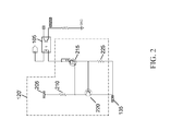
- FIG. 2 is another circuit diagram depicting an exemplary embodiment of a ground fault detection system.
- the present disclosure describes, among other things, certain embodiments of a ground fault detection system.
- the ground fault detection system can connect to a battery unit.
- a zero-voltage reference level also referred to herein as, “ground” or a “ground zero reference level”
- the system can output a signal indicating that a ground fault has been detected.
- a ground fault response system can respond to the signal by, for example, an outputting an audible or visible alarm or signaling a component to interrupt current flow to an enclosure or chassis.
- the ground fault detection system can be used in various contexts.
- the system can connect to battery units of a battery pack for an electric vehicle. If one of the battery units contacts the vehicle's chassis, the ground fault detection system can detect the ground fault and output a signal.
- the ground fault detection system can connect to a back up battery located in an electrical cabinet. The ground fault detection system can be used to sound an alarm to alert service personnel to the presence of a potential electric shock hazard.
- the ground fault detection system includes an optocoupler 105 having a light emitting diode 110 and a transistor 115 .
- One terminal of the light emitting diode 110 connects to an enclosure at ground (also referred to herein as “a node at a ground zero reference level”), such as a chassis of an electric vehicle.
- the other terminal of the light emitting diode 110 connects to a current sink 120 .
- One terminal of the transistor 115 connects to a voltage source 125 .
- the other terminal connects to a node corresponding to the output 128 of the optocoupler 105 (also referred to herein as the “output node”).
- This node connects to a resistor 130 that also connects to a ground zero reference level, which can be electrically isolated from the battery system.
- the current sink 120 connects to the negative terminal of a voltage source 135 .
- the positive terminal of the voltage source 135 connects to the negative terminal of battery unit 195 of the battery pack 190 .
- the optocoupler 105 In operation, when none of the terminals of the battery units 195 connect to the enclosure, current does not flow through the light emitting diode 110 of the optocoupler 105 .
- the light emitting diode 110 does not activate the transistor 115 , and the transistor 115 does not conduct. Because the node 128 corresponding to the optocoupler's 105 output is disconnected from the voltage source 125 , any charge at the node drains through the resistor 130 to ground, which can be electrically isolated. In this manner, the optocoupler 105 outputs a logic low signal, such as 0V, indicating that a ground fault has not been detected.
- any terminal of a battery unit 195 does connect to the enclosure, current flows through the light emitting diode 110 to the current sink 120 .
- the current activates the transistor 115 so the transistor 115 conducts.
- Current flows from the voltage source 125 , building charge at the output node 128 .
- the optocoupler 105 outputs a logic high signal indicating that a ground fault has been detected.
- the voltage sources 125 , 135 may be selected to suit the application.
- voltage source 125 can provide, e.g., 3.3V, although it should be understood that other voltages may be used.
- voltage source 135 can provide, e.g., 5.0V.
- the current sink 120 can limit the current flowing through itself and the light emitting diode 110 to a minimum level to indicate a ground fault.
- the current sink 120 may be designed to limit the current to 2 mA.
- the current sink 120 can operate over a range of voltages of the battery pack 190 , such as the voltages between the battery pack's 190 positive and negative terminals. In some embodiments, this range can be from about 5V to about 500V. In some embodiments, the current sink 120 can operate at voltages that exceed the voltage at the positive terminal of the battery pack 190 .
- FIG. 2 is another circuit diagram depicting an exemplary embodiment of a ground fault detection system.
- the embodiment includes the optocoupler 105 and voltage source 135 of FIG. 1 .
- the embodiment includes an exemplary implementation of a current sink 120 ′.
- the current sink 120 ′ includes a voltage source 205 , a first resistor 210 , a first transistor 215 , a second transistor 220 , and a second resistor 225 .
- the voltage source 205 connects to one terminal of the first resistor 210 .
- the other terminal of the first resistor 210 connects to the gate of the first transistor 215 and the emitter of the second transistor 220 .
- the drain of the first transistor 215 connects to the optocoupler 105 .
- the source of the first transistor 215 connects to the base of the second transistor 220 and one terminal of the second resistor 225 .
- the other terminal of the second resistor 225 connects to the source of the second transistor 225 and the negative terminal of the voltage source 135 .
- the transistor 215 can be any type of transistor, such as a metal-oxide-semiconductor field-effect transistor (MOSFET), an insulated gate bipolar transistor (IGBT), or an NPN transistor. In some embodiments, a 2N3904-type transistor is used for the second transistor 220 .
- MOSFET metal-oxide-semiconductor field-effect transistor
- IGBT insulated gate bipolar transistor
- NPN NPN transistor
- the present disclosure provides an efficient and intelligent ground fault detection system. Having described certain embodiments of the ground fault detection system, it will now become apparent to one of skill in the art that other embodiments incorporating the concepts of the disclosure may be used. Therefore, the invention should not be limited to certain embodiments, but should encompass the spirit and scope of the claims.
Landscapes
- Engineering & Computer Science (AREA)
- Life Sciences & Earth Sciences (AREA)
- Sustainable Development (AREA)
- Sustainable Energy (AREA)
- Power Engineering (AREA)
- Transportation (AREA)
- Mechanical Engineering (AREA)
- Physics & Mathematics (AREA)
- General Physics & Mathematics (AREA)
- Testing Of Short-Circuits, Discontinuities, Leakage, Or Incorrect Line Connections (AREA)
Abstract
Description
- In battery-operated electrical systems, isolating the battery from an enclosure (e.g., the chassis of an electric vehicle) can prevent electric shock to service personnel who may accidentally contact the enclosure while working on the battery. Current systems for detecting the connection between the enclosure and the battery (also referred to herein as connection or ground faults) rely on complex circuits when direct current is used. Some of these circuits include voltage dividers positioned across the battery. The circuits determine that a ground fault is present based on the value of a voltage measured on the voltage divider. Further, these circuits can include comparators, switched capacitors, and other components to ensure stable operation in the presence of noise. The number and arrangement of components thus make ground fault detection systems expensive to manufacture.
- A ground fault detection system can detect a connection between any terminal of any battery unit in a battery pack and a node at a potential below the zero-voltage reference level (e.g., the most negative battery terminal). The node can be an enclosure or a chassis. In particular, an optocoupler and a current sink can be connected in series to the enclosure, and a voltage source can be connected in series to the negative terminal of a battery unit. When any terminal of the battery units in the battery pack contacts the enclosure, current flows through a diode of the optocoupler and activates a transistor of the optocoupler. As the transistor conducts, the optocoupler outputs a logic high signal to indicate a ground fault has been detected.
- In one aspect, the present disclosure describes a ground fault detection system. The system includes an optocoupler, a current sink, and a first voltage source connected in series. The first voltage source connects to a negative terminal of a battery unit. Upon connection between any terminal of the battery unit and a first node at a ground zero reference level, current flows through the optocoupler and the current sink to cause the optocoupler to output a ground fault detection signal.
- The first node at a ground zero reference level can be a chassis of an electric vehicle. The ground fault detection signal can be a logic high signal. The optocoupler can output a logic low signal when the current does not flow through the optocoupler. The optocoupler can include a light emitting diode (LED) and a transistor. The current can flow through the light emitting diode to cause the transistor to conduct, and the conducting transistor can cause the optocoupler to output the ground fault detection signal.
- The light emitting diode can be connected to first and second terminals of the optocoupler and the transistor can be connected to third and fourth terminals of the optocoupler. The first terminal of the optocoupler can connect to a second node at the ground zero reference level, the second terminal of the optocoupler can connect to the current sink, the third terminal of the optocoupler can connect to a second voltage source, and the fourth terminal of the optocoupler can connect to a resistor connected in series with a third node at a zero voltage reference level. The current can flow through the light emitting diode from the first terminal of the optocoupler to the second terminal.
- The second voltage source and the node at the zero voltage reference level can be electrically isolated from the battery pack. The second voltage source can be a 3.3V source. A positive terminal of the first voltage source can connect to the negative terminal of the battery unit, and a negative terminal of the first voltage source can connect to the current sink. The first voltage source can be a 5V source. The current sink can limit the current flowing through the optocoupler and the current sink to about 2 mA. The current sink can operate at a voltage exceeding about 5V. The current sink can include a third voltage source, one or more transistors, and one or more resistors. The third voltage source, the one or more transistors, and the one or more resistors can be configured to form an equilibrium so that the current flowing through the current sink is a substantially constant current. Any of the transistors can be a metal-oxide-semiconductor field-effect transistor (MOSFET), an insulated gate bipolar transistor (IGBT), or an NPN transistor.
- In another aspect, the present disclosure describes a ground fault detection system with an optocoupler with a light emitting diode and a transistor, a current sink connected to the light emitting diode of the optocoupler, and a first voltage source with a negative terminal connected to the current sink and a positive terminal connected to a negative terminal of a battery unit. Upon connection between any terminal of the battery unit and a chassis of an electric vehicle, current flows through the light emitting diode of the optocoupler and the current sink, and the light emitting diode activates the transistor such that the optocoupler outputs a ground fault detection signal.
- In another aspect, the present disclosure describes a method of detecting a ground fault. The method includes connecting a positive terminal of a voltage source to a negative terminal of a battery unit, connecting a terminal of a battery unit to a node at a ground zero reference level, flowing a current through a light emitting diode of an optocoupler and a current source, and activating a transistor of the optocoupler such that the optocoupler outputs a ground fault detection signal. The method can also include deactivating the transistor of the optocoupler when the positive terminal of the battery unit is not connected to the node at the ground zero reference level, and connecting a terminal of the optocoupler to the ground zero reference level such that the optocoupler outputs a signal indicating that a ground fault is not detected.
- The foregoing and other objects, aspects, features, and advantages of the present invention will become more apparent and better understood by referring to the following description taken in conjunction with the accompanying drawings, in which:
-
FIG. 1 is a circuit diagram depicting an exemplary embodiment of a ground fault detection system; and -
FIG. 2 is another circuit diagram depicting an exemplary embodiment of a ground fault detection system. - The present disclosure describes, among other things, certain embodiments of a ground fault detection system. The ground fault detection system can connect to a battery unit. When the system detects that a terminal of the battery unit has connected to a zero-voltage reference level (also referred to herein as, “ground” or a “ground zero reference level”), the system can output a signal indicating that a ground fault has been detected. A ground fault response system can respond to the signal by, for example, an outputting an audible or visible alarm or signaling a component to interrupt current flow to an enclosure or chassis.
- The ground fault detection system can be used in various contexts. For example, the system can connect to battery units of a battery pack for an electric vehicle. If one of the battery units contacts the vehicle's chassis, the ground fault detection system can detect the ground fault and output a signal. In another example, the ground fault detection system can connect to a back up battery located in an electrical cabinet. The ground fault detection system can be used to sound an alarm to alert service personnel to the presence of a potential electric shock hazard.
- Referring now to
FIG. 1 , a circuit diagram depicting an exemplary embodiment of a ground fault detection system is shown and described. The ground fault detection system includes anoptocoupler 105 having alight emitting diode 110 and atransistor 115. One terminal of thelight emitting diode 110 connects to an enclosure at ground (also referred to herein as “a node at a ground zero reference level”), such as a chassis of an electric vehicle. The other terminal of thelight emitting diode 110 connects to acurrent sink 120. One terminal of thetransistor 115 connects to avoltage source 125. The other terminal connects to a node corresponding to theoutput 128 of the optocoupler 105 (also referred to herein as the “output node”). This node connects to aresistor 130 that also connects to a ground zero reference level, which can be electrically isolated from the battery system. Thecurrent sink 120 connects to the negative terminal of avoltage source 135. The positive terminal of thevoltage source 135 connects to the negative terminal of battery unit 195 of thebattery pack 190. - In operation, when none of the terminals of the battery units 195 connect to the enclosure, current does not flow through the
light emitting diode 110 of theoptocoupler 105. Thelight emitting diode 110 does not activate thetransistor 115, and thetransistor 115 does not conduct. Because thenode 128 corresponding to the optocoupler's 105 output is disconnected from thevoltage source 125, any charge at the node drains through theresistor 130 to ground, which can be electrically isolated. In this manner, theoptocoupler 105 outputs a logic low signal, such as 0V, indicating that a ground fault has not been detected. - When any terminal of a battery unit 195 does connect to the enclosure, current flows through the
light emitting diode 110 to thecurrent sink 120. The current activates thetransistor 115 so thetransistor 115 conducts. Current flows from thevoltage source 125, building charge at theoutput node 128. Thus, theoptocoupler 105 outputs a logic high signal indicating that a ground fault has been detected. - The
voltage sources voltage source 125 can provide, e.g., 3.3V, although it should be understood that other voltages may be used. In some implementations,voltage source 135 can provide, e.g., 5.0V. In some implementations, thecurrent sink 120 can limit the current flowing through itself and thelight emitting diode 110 to a minimum level to indicate a ground fault. For example, in some implementations, thecurrent sink 120 may be designed to limit the current to 2 mA. Thecurrent sink 120 can operate over a range of voltages of thebattery pack 190, such as the voltages between the battery pack's 190 positive and negative terminals. In some embodiments, this range can be from about 5V to about 500V. In some embodiments, thecurrent sink 120 can operate at voltages that exceed the voltage at the positive terminal of thebattery pack 190. -
FIG. 2 is another circuit diagram depicting an exemplary embodiment of a ground fault detection system. The embodiment includes theoptocoupler 105 andvoltage source 135 ofFIG. 1 . The embodiment includes an exemplary implementation of acurrent sink 120′. Thecurrent sink 120′ includes avoltage source 205, afirst resistor 210, afirst transistor 215, asecond transistor 220, and asecond resistor 225. Thevoltage source 205 connects to one terminal of thefirst resistor 210. The other terminal of thefirst resistor 210 connects to the gate of thefirst transistor 215 and the emitter of thesecond transistor 220. The drain of thefirst transistor 215 connects to theoptocoupler 105. The source of thefirst transistor 215 connects to the base of thesecond transistor 220 and one terminal of thesecond resistor 225. The other terminal of thesecond resistor 225 connects to the source of thesecond transistor 225 and the negative terminal of thevoltage source 135. - In operation, current flows from the
voltage source 205 through thefirst resistor 210 to activate thefirst transistor 215 such that thefirst transistor 215 conducts. When a positive terminal of a battery unit 195 connects to ground, current flows through theoptocoupler 105, thefirst transistor 215, and thesecond resistor 225. The voltage that develops across thesecond resistor 225 activates thesecond transistor 220. As the second transistor conducts 220, current is diverted from the gate oftransistor 215. Thetransistors resistors first transistor 215. - The
transistor 215 can be any type of transistor, such as a metal-oxide-semiconductor field-effect transistor (MOSFET), an insulated gate bipolar transistor (IGBT), or an NPN transistor. In some embodiments, a 2N3904-type transistor is used for thesecond transistor 220. - In view of the structure, functions and apparatus of the system described herein, the present disclosure provides an efficient and intelligent ground fault detection system. Having described certain embodiments of the ground fault detection system, it will now become apparent to one of skill in the art that other embodiments incorporating the concepts of the disclosure may be used. Therefore, the invention should not be limited to certain embodiments, but should encompass the spirit and scope of the claims.
Claims (20)
Priority Applications (1)
| Application Number | Priority Date | Filing Date | Title |
|---|---|---|---|
| US13/077,145 US9024639B2 (en) | 2011-03-31 | 2011-03-31 | Ground fault detection system |
Applications Claiming Priority (1)
| Application Number | Priority Date | Filing Date | Title |
|---|---|---|---|
| US13/077,145 US9024639B2 (en) | 2011-03-31 | 2011-03-31 | Ground fault detection system |
Publications (2)
| Publication Number | Publication Date |
|---|---|
| US20120249154A1 true US20120249154A1 (en) | 2012-10-04 |
| US9024639B2 US9024639B2 (en) | 2015-05-05 |
Family
ID=46926364
Family Applications (1)
| Application Number | Title | Priority Date | Filing Date |
|---|---|---|---|
| US13/077,145 Active 2033-03-19 US9024639B2 (en) | 2011-03-31 | 2011-03-31 | Ground fault detection system |
Country Status (1)
| Country | Link |
|---|---|
| US (1) | US9024639B2 (en) |
Cited By (10)
| Publication number | Priority date | Publication date | Assignee | Title |
|---|---|---|---|---|
| US20130154660A1 (en) * | 2011-12-19 | 2013-06-20 | Tyco Safety Products Canada Ltd. | System and method for ground fault detection and fault type evaluation |
| US20150270584A1 (en) * | 2012-08-10 | 2015-09-24 | Battelle Memorial Institute | Optical waveguide methods for detecting internal faults in operating batteries |
| US20170074944A1 (en) * | 2015-09-15 | 2017-03-16 | Lg Chem, Ltd. | Test system and method for testing a battery pack |
| WO2017125434A1 (en) * | 2016-01-20 | 2017-07-27 | Marquardt Gmbh | Insulation measurement for a battery system |
| US20180238952A1 (en) * | 2017-02-21 | 2018-08-23 | Delta Electronics (Shanghai) Co., Ltd | Grounding wire detection circuit |
| US10177421B2 (en) | 2015-02-12 | 2019-01-08 | Battelle Memorial Institute | Battery cell structure with limited cell penetrations |
| US10211489B2 (en) | 2012-08-10 | 2019-02-19 | Battelle Memorial Institute | Integral light sources and detectors for an optical sensor to detect battery faults |
| US10439255B2 (en) | 2012-08-10 | 2019-10-08 | Battelle Memorial Institute | Optical monitoring of battery health |
| CN112881915A (en) * | 2021-01-18 | 2021-06-01 | 恒大新能源汽车投资控股集团有限公司 | Fault identification method and device for lithium battery and computer readable storage medium |
| US11329589B2 (en) | 2012-03-28 | 2022-05-10 | Joy Global Underground Mining Llc | Ground fault detection methods on variable frequency drive systems |
Families Citing this family (1)
| Publication number | Priority date | Publication date | Assignee | Title |
|---|---|---|---|---|
| US10274530B2 (en) * | 2015-07-22 | 2019-04-30 | Honeywell International Inc. | System and method for dynamic ground fault detection |
Citations (23)
| Publication number | Priority date | Publication date | Assignee | Title |
|---|---|---|---|---|
| US4188574A (en) * | 1978-03-27 | 1980-02-12 | Instrumentation Specialties Company | AC Detector for DC ground faults and high capacitance in high-voltage DC power supplies |
| US4809123A (en) * | 1986-04-14 | 1989-02-28 | Isco, Inc. | Ground fault detector for high-voltage DC power supplies |
| US5064104A (en) * | 1988-10-28 | 1991-11-12 | Milancolimited, Inc. | Apparatus for vending a product |
| US5363047A (en) * | 1992-10-30 | 1994-11-08 | Southern California Edison Company | Portable ground fault detector |
| US5510658A (en) * | 1993-05-12 | 1996-04-23 | Honda Giken Kogyo Kabushiki Kaisha | Circuit breaker device for electric vehicle |
| US5682314A (en) * | 1994-11-10 | 1997-10-28 | Mitsubishi Denki Kabushiki Kaisha | Controller apparatus for vehicle |
| US6031354A (en) * | 1996-02-01 | 2000-02-29 | Aims Systems, Inc. | On-line battery management and monitoring system and method |
| US6218647B1 (en) * | 1998-01-19 | 2001-04-17 | Msx, Inc. | Method and apparatus for using direct current to detect ground faults in a shielded heater wire |
| US20020125837A1 (en) * | 2001-03-09 | 2002-09-12 | Lecip Corporation | Sign lamp lighting transformer with protective functions |
| US20030234653A1 (en) * | 2002-02-06 | 2003-12-25 | Ballard Power Systems Ag | Method and device for insulation monitoring of a DC network |
| US20040157091A1 (en) * | 2003-02-07 | 2004-08-12 | Scott Dewey | Multi-stack isolation detection system |
| US20040199343A1 (en) * | 2003-04-01 | 2004-10-07 | Cardinal Mark E. | Integrated, self-powered battery monitoring device and system |
| US20050036249A1 (en) * | 2003-08-15 | 2005-02-17 | Harvey Ronald C. | Threshold adjustment accuracy for ground fault condition determination |
| US7049825B2 (en) * | 2004-04-15 | 2006-05-23 | Bae Systems Controls, Inc. | DC ground fault detection with resistive centering |
| US20080174922A1 (en) * | 2007-01-19 | 2008-07-24 | Tellabs Bedford, Inc. | Method and apparatus for detecting ground fault current on a power line |
| US20090015434A1 (en) * | 2006-03-16 | 2009-01-15 | Adc Dsl Systems, Inc. | Enhanced ac immunity in ground fault detection |
| JP2009270999A (en) * | 2008-05-09 | 2009-11-19 | Murata Mach Ltd | Earth fault detecting circuit and earth fault detecting method |
| US20090295401A1 (en) * | 2008-05-27 | 2009-12-03 | Seiji Kamata | Leak detecting circuit |
| US20100007312A1 (en) * | 2008-07-10 | 2010-01-14 | Plamen Petkov | Isolated generator control unit (gcu) |
| US20100123465A1 (en) * | 2008-11-14 | 2010-05-20 | Richard Owens | Automotive battery circuit fault detection |
| US20110025341A1 (en) * | 2009-07-31 | 2011-02-03 | Simplexgrinnell Lp | Ground fault detection |
| US20110115564A1 (en) * | 2009-11-06 | 2011-05-19 | Tung Chiayao S | Short Circuits and Power Limit Protection Circuits |
| US20110286134A1 (en) * | 2010-05-19 | 2011-11-24 | Schneider Electric USA, Inc. | Earth leakage detection module with robust transient suppression |
-
2011
- 2011-03-31 US US13/077,145 patent/US9024639B2/en active Active
Patent Citations (24)
| Publication number | Priority date | Publication date | Assignee | Title |
|---|---|---|---|---|
| US4188574A (en) * | 1978-03-27 | 1980-02-12 | Instrumentation Specialties Company | AC Detector for DC ground faults and high capacitance in high-voltage DC power supplies |
| US4809123A (en) * | 1986-04-14 | 1989-02-28 | Isco, Inc. | Ground fault detector for high-voltage DC power supplies |
| US5064104A (en) * | 1988-10-28 | 1991-11-12 | Milancolimited, Inc. | Apparatus for vending a product |
| US5363047A (en) * | 1992-10-30 | 1994-11-08 | Southern California Edison Company | Portable ground fault detector |
| US5510658A (en) * | 1993-05-12 | 1996-04-23 | Honda Giken Kogyo Kabushiki Kaisha | Circuit breaker device for electric vehicle |
| US5682314A (en) * | 1994-11-10 | 1997-10-28 | Mitsubishi Denki Kabushiki Kaisha | Controller apparatus for vehicle |
| US6031354A (en) * | 1996-02-01 | 2000-02-29 | Aims Systems, Inc. | On-line battery management and monitoring system and method |
| US6218647B1 (en) * | 1998-01-19 | 2001-04-17 | Msx, Inc. | Method and apparatus for using direct current to detect ground faults in a shielded heater wire |
| US20020125837A1 (en) * | 2001-03-09 | 2002-09-12 | Lecip Corporation | Sign lamp lighting transformer with protective functions |
| US20030234653A1 (en) * | 2002-02-06 | 2003-12-25 | Ballard Power Systems Ag | Method and device for insulation monitoring of a DC network |
| US20040157091A1 (en) * | 2003-02-07 | 2004-08-12 | Scott Dewey | Multi-stack isolation detection system |
| US20040199343A1 (en) * | 2003-04-01 | 2004-10-07 | Cardinal Mark E. | Integrated, self-powered battery monitoring device and system |
| US20050036249A1 (en) * | 2003-08-15 | 2005-02-17 | Harvey Ronald C. | Threshold adjustment accuracy for ground fault condition determination |
| US7049825B2 (en) * | 2004-04-15 | 2006-05-23 | Bae Systems Controls, Inc. | DC ground fault detection with resistive centering |
| US20090015434A1 (en) * | 2006-03-16 | 2009-01-15 | Adc Dsl Systems, Inc. | Enhanced ac immunity in ground fault detection |
| US7821413B2 (en) * | 2006-03-16 | 2010-10-26 | Adc Dsl Systems, Inc. | Enhanced AC immunity in ground fault detection |
| US20080174922A1 (en) * | 2007-01-19 | 2008-07-24 | Tellabs Bedford, Inc. | Method and apparatus for detecting ground fault current on a power line |
| JP2009270999A (en) * | 2008-05-09 | 2009-11-19 | Murata Mach Ltd | Earth fault detecting circuit and earth fault detecting method |
| US20090295401A1 (en) * | 2008-05-27 | 2009-12-03 | Seiji Kamata | Leak detecting circuit |
| US20100007312A1 (en) * | 2008-07-10 | 2010-01-14 | Plamen Petkov | Isolated generator control unit (gcu) |
| US20100123465A1 (en) * | 2008-11-14 | 2010-05-20 | Richard Owens | Automotive battery circuit fault detection |
| US20110025341A1 (en) * | 2009-07-31 | 2011-02-03 | Simplexgrinnell Lp | Ground fault detection |
| US20110115564A1 (en) * | 2009-11-06 | 2011-05-19 | Tung Chiayao S | Short Circuits and Power Limit Protection Circuits |
| US20110286134A1 (en) * | 2010-05-19 | 2011-11-24 | Schneider Electric USA, Inc. | Earth leakage detection module with robust transient suppression |
Non-Patent Citations (2)
| Title |
|---|
| http://www1.electusdistribution.com.au/images_uploaded/optocoup.pdf * |
| https://www.fairchildsemi.com/ds/FO/FOD3180.pdf * |
Cited By (15)
| Publication number | Priority date | Publication date | Assignee | Title |
|---|---|---|---|---|
| US20130154660A1 (en) * | 2011-12-19 | 2013-06-20 | Tyco Safety Products Canada Ltd. | System and method for ground fault detection and fault type evaluation |
| US9134354B2 (en) * | 2011-12-19 | 2015-09-15 | Tyco Safety Products Canada Ltd. | System and method for ground fault detection and fault type evaluation |
| US11329589B2 (en) | 2012-03-28 | 2022-05-10 | Joy Global Underground Mining Llc | Ground fault detection methods on variable frequency drive systems |
| US10211489B2 (en) | 2012-08-10 | 2019-02-19 | Battelle Memorial Institute | Integral light sources and detectors for an optical sensor to detect battery faults |
| US9570781B2 (en) * | 2012-08-10 | 2017-02-14 | Battelle Memorial Institute | Optical waveguide methods for detecting internal faults in operating batteries |
| US10439255B2 (en) | 2012-08-10 | 2019-10-08 | Battelle Memorial Institute | Optical monitoring of battery health |
| US20150270584A1 (en) * | 2012-08-10 | 2015-09-24 | Battelle Memorial Institute | Optical waveguide methods for detecting internal faults in operating batteries |
| US10177421B2 (en) | 2015-02-12 | 2019-01-08 | Battelle Memorial Institute | Battery cell structure with limited cell penetrations |
| US20170074944A1 (en) * | 2015-09-15 | 2017-03-16 | Lg Chem, Ltd. | Test system and method for testing a battery pack |
| US10371758B2 (en) * | 2015-09-15 | 2019-08-06 | Lg Chem, Ltd. | Test system and method for testing a battery pack |
| WO2017125434A1 (en) * | 2016-01-20 | 2017-07-27 | Marquardt Gmbh | Insulation measurement for a battery system |
| US20180238952A1 (en) * | 2017-02-21 | 2018-08-23 | Delta Electronics (Shanghai) Co., Ltd | Grounding wire detection circuit |
| CN108459227A (en) * | 2017-02-21 | 2018-08-28 | 台达电子企业管理(上海)有限公司 | Ground line detection circuit |
| US10627454B2 (en) * | 2017-02-21 | 2020-04-21 | Delta Electronics (Shanghai) Co., Ltd | Grounding wire detection circuit |
| CN112881915A (en) * | 2021-01-18 | 2021-06-01 | 恒大新能源汽车投资控股集团有限公司 | Fault identification method and device for lithium battery and computer readable storage medium |
Also Published As
| Publication number | Publication date |
|---|---|
| US9024639B2 (en) | 2015-05-05 |
Similar Documents
| Publication | Publication Date | Title |
|---|---|---|
| US9024639B2 (en) | Ground fault detection system | |
| JP5139022B2 (en) | Overvoltage protection circuit and power management circuit and electronic equipment using the same | |
| US9461455B2 (en) | Protecting circuit | |
| US8472157B2 (en) | Overvoltage and overcurrent protection circuit | |
| US7791494B2 (en) | Voltage monitoring device | |
| US8493701B2 (en) | Overvoltage protection circuit | |
| US8913361B2 (en) | Overvoltage protection circuit and portable electronic device comprising same | |
| KR101842338B1 (en) | Light-emitting diode driving apparatus | |
| TWI512310B (en) | Three-phase power abnormality detecting device | |
| WO2016082787A1 (en) | Circuit failure detection device, led based light emitting apparatus and light/signal emitting device for a vehicle | |
| US9772384B2 (en) | Alternating current input voltage detecting device | |
| US20080024138A1 (en) | Identifying apparatus for ac power supply arrangement | |
| US7982626B2 (en) | Proper grounding detection and alarm circuit for electronic device | |
| CN215894733U (en) | Voltage signal detection circuit, power supply device and electric device | |
| US10921384B2 (en) | Disconnection sensing circuit and electrical connection box | |
| JP4780775B2 (en) | Power supply LED lamp protection circuit | |
| US9966834B2 (en) | Power supply protecting apparatus | |
| US9632116B2 (en) | DC reverse polarity detection | |
| US20130234676A1 (en) | Charge indicator circuit | |
| US9857400B2 (en) | Motherboard voltage testing device | |
| US20140347063A1 (en) | Fan test device | |
| US9906011B2 (en) | Electronic device and over-current protection circuit thereof | |
| US20140265630A1 (en) | Phase detection circuit | |
| US20160126785A1 (en) | Alarm system for power supply | |
| US9682650B2 (en) | Direction indicator system and direction indicator device for a vehicle |
Legal Events
| Date | Code | Title | Description |
|---|---|---|---|
| AS | Assignment |
Owner name: ELITE POWER SOLUTIONS LLC, ARIZONA Free format text: ASSIGNMENT OF ASSIGNORS INTEREST;ASSIGNORS:DAO, YUAN;SCHLANGER, WILLIAM;REEL/FRAME:035176/0320 Effective date: 20150316 |
|
| STCF | Information on status: patent grant |
Free format text: PATENTED CASE |
|
| MAFP | Maintenance fee payment |
Free format text: PAYMENT OF MAINTENANCE FEE, 4TH YR, SMALL ENTITY (ORIGINAL EVENT CODE: M2551); ENTITY STATUS OF PATENT OWNER: SMALL ENTITY Year of fee payment: 4 |
|
| AS | Assignment |
Owner name: LEGALINC CORPORATE SERVICES INC., NEVADA Free format text: ASSIGNMENT OF ASSIGNORS INTEREST;ASSIGNOR:ELITE POWER SOLUTIONS LLC;REEL/FRAME:049171/0468 Effective date: 20190513 |
|
| AS | Assignment |
Owner name: ELITE POWER HOLDINGS LLC, NEVADA Free format text: CORRECTIVE ASSIGNMENT TO CORRECT THE RECEIVING PARTY NAME PREVIOUSLY RECORDED AT REEL: 049171 FRAME: 0468. ASSIGNOR(S) HEREBY CONFIRMS THE ASSIGNMENT;ASSIGNOR:ELITE POWER SOLUTIONS LLC;REEL/FRAME:049546/0439 Effective date: 20190516 |
|
| AS | Assignment |
Owner name: ELITE POWER HOLDINGS LLC, NEVADA Free format text: CHANGE OF ADDRESS OF ASSIGNEE;ASSIGNOR:ELITE POWER HOLDINGS LLC;REEL/FRAME:054122/0646 Effective date: 20201019 |
|
| MAFP | Maintenance fee payment |
Free format text: PAYMENT OF MAINTENANCE FEE, 8TH YR, SMALL ENTITY (ORIGINAL EVENT CODE: M2552); ENTITY STATUS OF PATENT OWNER: SMALL ENTITY Year of fee payment: 8 |