US20120249128A1 - Magnetic sensor system - Google Patents
Magnetic sensor system Download PDFInfo
- Publication number
- US20120249128A1 US20120249128A1 US13/404,495 US201213404495A US2012249128A1 US 20120249128 A1 US20120249128 A1 US 20120249128A1 US 201213404495 A US201213404495 A US 201213404495A US 2012249128 A1 US2012249128 A1 US 2012249128A1
- Authority
- US
- United States
- Prior art keywords
- linear
- conducting member
- flux conducting
- field
- sensor
- Prior art date
- Legal status (The legal status is an assumption and is not a legal conclusion. Google has not performed a legal analysis and makes no representation as to the accuracy of the status listed.)
- Abandoned
Links
Images


Classifications
-
- G—PHYSICS
- G01—MEASURING; TESTING
- G01R—MEASURING ELECTRIC VARIABLES; MEASURING MAGNETIC VARIABLES
- G01R33/00—Arrangements or instruments for measuring magnetic variables
- G01R33/0011—Arrangements or instruments for measuring magnetic variables comprising means, e.g. flux concentrators, flux guides, for guiding or concentrating the magnetic flux, e.g. to the magnetic sensor
Definitions
- the present disclosure relates to magnetic sensor systems, and more particularly, to magnetic sensor systems that sense magnetic flux.
- Transmissions and other powertrain components in automotive vehicles are complex mechanisms controlled by hydraulic systems and electronic control modules.
- transmissions typically include a plurality of sensors that communicate information indicative of the operating state of the transmission to the electronic controller.
- These sensors take many forms and perform various functions.
- one or more linear displacement sensors are used to measure the relative position of the clutches in order to determine engagement state.
- linear displacement sensor in certain environments, it is possible for the linear displacement sensor to have dead-band locations where the magnetic flux is redirected or interfered with due to other nearby components. While current linear displacement sensors are useful for their intended purpose, there is room in the art for an improved linear displacement sensor system that reduces or eliminates magnetic flux interference in magnetically difficult areas of a transmission.
- a linear sensor system includes a first field sensor displaced linearly from a second field sensor.
- a member having high magnetic permeability is disposed between the first field sensor and the second field sensor.
- the member is optimized in shape and material to remove any redirection or interference of the magnetic flux in the field sensors.
- a linear sensor system has a first field sensor and a second field sensor spaced apart from the first field sensor.
- the system further includes a flux conducting member having a magnetic permeability that is greater than or equal to the magnetic permeability of steel.
- the flux conducting member is disposed between the first field sensor and the second field sensor.
- a linear sensor system in another form, which may be combined with or separate from the other forms described herein, includes a first permanent magnetic linear contactless displacement sensor having a first magnetic core surrounded by a first coil and a second permanent magnetic linear contactless displacement sensor having a second magnetic core surrounded by a second coil.
- a flux conducting member formed of either low carbon steel or mu-metal is disposed between the first and second sensors.
- the flux conducting member is axially aligned with the first magnetic core and with the second magnetic core.
- An insulative material surrounds the first and second field sensors and the flux conducting member, wherein the first and second field sensors and the flux conducting member are disposed within the insulative material.
- a torque transmitting device for a transmission.
- the torque transmitting device includes an input member, a driven shaft having a shaft magnetic permeability, a clutch assembly selectively connecting the input member to the driven shaft, and an activating member having a main body and a permanent magnet attached to the main body.
- the actuating member is configured to move in a linear direction to activate the clutch assembly to connect the input member to the driven shaft.
- the torque transmitting device further includes a sensor system.
- the sensor system has a first field sensor, a second field sensor spaced apart from the first field sensor, and a flux conducting member having a member magnetic permeability that is higher than the shaft magnetic permeability of the driven shaft.
- the flux conducting member is disposed between the first field sensor and the second field sensor.
- the sensor system is operable to sense a linear displacement of the activating member.
- a linear sensor system in another form, which may be combined with or separate from the other forms described herein, includes a first field sensor, a second field sensor spaced apart from the first field sensor, and a flux conducting member having a magnetic permeability that is higher than the magnetic permeability of surrounding structures.
- the flux conducting member is disposed between the first field sensor and the second field sensor.
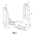
- FIG. 1 is a cross section of a portion of an exemplary dual clutch transmission showing an exemplary dual clutch actuation system
- FIG. 2 is perspective view of a sensor housing used in the dual clutch actuation system
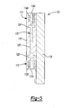
- FIG. 3 is a top view of a PLOD sensor according to the principles of the present invention.
- FIG. 4 is a cross-section of the PLOD sensor shown in FIG. 3 ;
- FIG. 5 is a cross-section the PLOD sensor of FIG. 3 having another variation of a flux conducting member, in accordance with the principles of the present invention
- FIG. 6 is a graph illustrating dead-band of an output of another sensor system.
- FIG. 7 is a graph illustrating an output curve of a sensor system with no dead-band, in accordance with the principles of the present invention.
- a torque transmitting device for a dual input transmission (not shown) is generally indicated by reference number 10 .
- the torque transmitting device 10 is for example a dual clutch disposed in a vehicle powertrain.
- the vehicle powertrain includes an engine and a transmission.
- the transmission is a dual input transmission where torque is transferred from the engine via a crankshaft 11 to two input shafts in the transmission including a first input shaft 12 and a second input shaft 14 through selective operation of the torque transmitting device 10 .
- the second input shaft 14 is a sleeve (or hollow) shaft that is concentric with and overlies the first input shaft 12 .
- the torque transmitting device 10 is disposed in a transmission housing or bell housing (not shown).
- the torque transmitting device 10 has two separate and independent friction clutches 16 and 18 .
- the clutches 16 and 18 are rotationally fixed to a flywheel 25 .
- the flywheel 25 is rotationally fixed to the crankshaft 11 and is preferably a dual mass flywheel that is configured to dampen and reduce vibration in the crankshaft 11 .
- the torque transmitting device 10 includes a central hub 30 rotationally connected with the outer hub.
- the central hub 30 is supported for rotation relative to the sleeve shaft 14 via a plurality of bearings 28 .
- the central hub 30 includes a fixed friction plate that is fixed from movement in an axial direction.
- the friction clutches 16 and 18 each include friction members 32 and 34 , respectively.
- the friction member 32 is connected to the input shaft 12 .
- the friction member 34 is connected to the sleeve shaft 14 .
- the friction members 32 , 34 are disposed on either side of the axially fixed friction plate of the central hub 30 .
- the friction clutches 16 and 18 are engaged with the friction plate of the central hub 30 through axially moveable apply members 36 and 38 , respectively.
- the apply members 36 and 38 are each selectively translatable in an axial direction to engage one of the friction members 32 and 34 in order to couple the crankshaft 11 with one of the input shafts 12 and 14 .
- the apply members 36 and 38 are selectively actuated by a lever actuation assembly 50 .
- the lever actuation assembly 50 includes a pair of annular pistons 52 and 54 disposed in a cylinder housing 55 .
- the cylinder housing 55 is rotationally fixed relative to the transmission.
- a pair of annular bearing assemblies 56 and 58 are each connected with ends of the annular pistons 52 and 54 , respectively.
- the annular pistons 52 and 54 are configured to translate within the cylinder housing 55 when actuated by hydraulic fluid.
- the annular pistons 52 and 54 and the annular bearings 56 and 58 are radially aligned such that the annular piston 52 and the annular bearing 56 are engageable with the apply member 36 to selectively engage the first clutch 16 and the annular piston 54 and annular bearing 58 are engageable with the apply member 38 to selectively engage the second clutch 18 .
- the bearing assemblies 56 and 58 are actuation bearings that torsionally decouple the rotating elements of the dual clutch 10 (i.e. the first and second members 36 and 38 ) from the non-rotating members of the actuation device 50 (i.e. the pistons 52 and 54 ).
- the torque transmitting device 10 further includes a clutch actuation sensor assembly 100 operable to sense the engagement of the clutches 16 and 18 by sensing the linear displacement of the pistons 52 and 54 .
- the sensor assembly 100 includes an inner permanent magnetic linear contactless displacement (PLOD) sensor 102 and an outer PLOD sensor 104 .
- the PLOD sensors 102 , 104 are disposed within a sensor housing 106 , best shown in FIG. 2 .
- the sensor housing 106 is coupled to the cylinder housing 55 and is configured to position the PLOD sensors 102 , 104 proximate an inner permanent magnet 108 and an outer permanent magnet 110 , respectively.
- the inner magnet 108 is coupled to the annular piston 54 and the outer magnet 110 is coupled to the annular piston 52 .
- the PLOD sensors 102 , 104 are operable to detect a magnetic field induced by the magnetic flux of the magnets 108 , 110 as they are displaced by translation of the annular pistons 52 and 54 .
- the PLOD sensor 102 includes a first field sensor 112 and a second field sensor 114 .
- the first field sensor 112 includes a magnetic core 112 A surrounded by a coil 112 B.
- the second field sensor 114 includes a magnetic core 114 A surrounded by a coil 114 B.
- Both field sensors 112 and 114 are supported in an insulative material 116 that is attached to a substrate or backing 118 .
- the insulative material 116 could be a plastic, such as printed circuit board (PCB), by way of example.
- the first field sensor 112 is spaced axially apart and away from the second field sensor 114 .
- a flux conducting member 120 is disposed between the first and second field sensors 112 , 114 within the insulative material 116 .
- the member 120 is axially aligned with the magnetic cores 112 A, 114 A.
- the member 120 has a high magnetic permeability.
- the member 120 may have various shapes and sizes and be made from various materials without departing from the scope of the present invention. In the example provided, the member 120 is a rectangular steel bar.
- the member 120 is optimized to have equal to or higher magnetic permeability than any surrounding structures, including, for example, the sleeve shaft 14 which may be made from 5120 steel.
- the member 120 prevents the magnetic flux of the magnet 108 from being redirected by surrounding structures, thereby preventing weakening of the magnetic field detected in the first and second field sensors 112 , 114 as the magnet 108 is translated by the movement of the annular piston 54 .
- the member 120 could be low carbon steel, mu-metal, or any other material having a magnetic permeability that is equal to or greater than the magnetic permeability of steel, by way of example.
- Mu-metal is a nickel-iron alloy, comprising mostly nickel, and also comprising iron, copper, and chromium or molybdenum.
- the cross section of the flux conducting member 120 has a generally rectangular shape, with a first end 122 that is located adjacent to the first field sensor 112 and a second end 124 that is located adjacent to the second field sensor 114 .
- the flux conducting member 120 could have any other number of shapes without falling beyond the spirit and scope of the present disclosure; for example, the flux conducting member 120 could have a cylindrical shape or an irregular shape.
- FIG. 5 another variation of the cross-section of the flux conducting member is illustrated and generally designated at 120 ′.
- the cross section of the flux conducting member 120 ′ has the shape of long “H”.
- the flux conducting member 120 ′ has a first 122 ′ located adjacent to the first field sensor 112 and a second end 124 ′ located adjacent to the second field sensor 114 .
- the first and second ends 122 ′, 124 ′ are wider than a thin body portion 126 ′ that connects the first and second ends 122 ′, 124 ′.
- the flux conducting member's 120 ′ H-shape cross-section resembles a rectangle that has portions cut away at its sides.
- the flux conducting member 120 , 120 ′ could have any other suitable shape, without falling beyond the spirit and scope of the present disclosure.
- the rest of the sensor 102 illustrated in FIG. 5 remains the same as the sensor 102 as described in the other figures.
- the member 120 specifically strengthens the magnetic field at the field sensor 112 , 114 locations in the same direction as the effective magnetic flux that the field sensors 112 , 114 are sensing.
- a design optimization is used to find the best size of the member 120 which completely removes any dead-band (i.e. no relationship between detected magnetic flux in the field sensors 112 , 114 and linear placement of the magnet 108 ) in the sensor output. This dead-band is illustrated in the graph of FIG. 6 .
- the member 120 also improves the linearity of the PLOD sensor's output curve (of detected magnetic flux to distance stroked) over the entire stroke of the magnet 108 , as shown in the graph of FIG. 7 . Therefore the output of the PLOD sensor 102 is much more robust and able to resist the interference of any adjacent ferrous parts, has better linearity of detected current versus displacement, and has better signal to noise ratio.
Landscapes
- Physics & Mathematics (AREA)
- Condensed Matter Physics & Semiconductors (AREA)
- General Physics & Mathematics (AREA)
- Force Measurement Appropriate To Specific Purposes (AREA)
- Measurement Of Length, Angles, Or The Like Using Electric Or Magnetic Means (AREA)
Abstract
Description
- This application claims the benefit of U.S. Provisional Application No. 61/468,465, filed on Mar. 28, 2011, which is herein incorporated by reference in its entirety.
- The present disclosure relates to magnetic sensor systems, and more particularly, to magnetic sensor systems that sense magnetic flux.
- The statements in this section merely provide background information related to the present disclosure and may or may not constitute prior art.
- Transmissions and other powertrain components in automotive vehicles are complex mechanisms controlled by hydraulic systems and electronic control modules. In order to provide proper control, it is desirable to have feedback on the operating conditions and performance of the transmission as the transmission operates. For example, transmissions typically include a plurality of sensors that communicate information indicative of the operating state of the transmission to the electronic controller. These sensors take many forms and perform various functions. For example, it is often desirable to determine the engagement condition of a torque transmitting device, such as the clutches used in a dual clutch transmission. Accordingly, one or more linear displacement sensors are used to measure the relative position of the clutches in order to determine engagement state.
- However, in certain environments, it is possible for the linear displacement sensor to have dead-band locations where the magnetic flux is redirected or interfered with due to other nearby components. While current linear displacement sensors are useful for their intended purpose, there is room in the art for an improved linear displacement sensor system that reduces or eliminates magnetic flux interference in magnetically difficult areas of a transmission.
- A linear sensor system includes a first field sensor displaced linearly from a second field sensor. A member having high magnetic permeability is disposed between the first field sensor and the second field sensor. The member is optimized in shape and material to remove any redirection or interference of the magnetic flux in the field sensors.
- In one form, a linear sensor system is provided that has a first field sensor and a second field sensor spaced apart from the first field sensor. The system further includes a flux conducting member having a magnetic permeability that is greater than or equal to the magnetic permeability of steel. The flux conducting member is disposed between the first field sensor and the second field sensor.
- In another form, which may be combined with or separate from the other forms described herein, a linear sensor system is provided that includes a first permanent magnetic linear contactless displacement sensor having a first magnetic core surrounded by a first coil and a second permanent magnetic linear contactless displacement sensor having a second magnetic core surrounded by a second coil. A flux conducting member formed of either low carbon steel or mu-metal is disposed between the first and second sensors. The flux conducting member is axially aligned with the first magnetic core and with the second magnetic core. An insulative material surrounds the first and second field sensors and the flux conducting member, wherein the first and second field sensors and the flux conducting member are disposed within the insulative material.
- In another form, which may be combined with or separate from the other forms described herein, a torque transmitting device for a transmission is provided. The torque transmitting device includes an input member, a driven shaft having a shaft magnetic permeability, a clutch assembly selectively connecting the input member to the driven shaft, and an activating member having a main body and a permanent magnet attached to the main body. The actuating member is configured to move in a linear direction to activate the clutch assembly to connect the input member to the driven shaft. The torque transmitting device further includes a sensor system. The sensor system has a first field sensor, a second field sensor spaced apart from the first field sensor, and a flux conducting member having a member magnetic permeability that is higher than the shaft magnetic permeability of the driven shaft. The flux conducting member is disposed between the first field sensor and the second field sensor. The sensor system is operable to sense a linear displacement of the activating member.
- In another form, which may be combined with or separate from the other forms described herein, a linear sensor system is provided that includes a first field sensor, a second field sensor spaced apart from the first field sensor, and a flux conducting member having a magnetic permeability that is higher than the magnetic permeability of surrounding structures. The flux conducting member is disposed between the first field sensor and the second field sensor.
- Further areas of applicability will become apparent from the description provided herein. It should be understood that the description and specific examples are intended for purposes of illustration only and are not intended to limit the scope of the present disclosure.
- The drawings described herein are for illustration purposes only and are not intended to limit the scope of the present disclosure in any way.
-
FIG. 1 is a cross section of a portion of an exemplary dual clutch transmission showing an exemplary dual clutch actuation system; -
FIG. 2 is perspective view of a sensor housing used in the dual clutch actuation system; -
FIG. 3 is a top view of a PLOD sensor according to the principles of the present invention; -
FIG. 4 is a cross-section of the PLOD sensor shown inFIG. 3 ; -
FIG. 5 is a cross-section the PLOD sensor ofFIG. 3 having another variation of a flux conducting member, in accordance with the principles of the present invention; -
FIG. 6 is a graph illustrating dead-band of an output of another sensor system; and -
FIG. 7 is a graph illustrating an output curve of a sensor system with no dead-band, in accordance with the principles of the present invention. - The following description is merely exemplary in nature and is not intended to limit the present disclosure, application, or uses.
- With reference to
FIG. 1 , a torque transmitting device for a dual input transmission (not shown) is generally indicated byreference number 10. The torque transmittingdevice 10 is for example a dual clutch disposed in a vehicle powertrain. Typically the vehicle powertrain includes an engine and a transmission. In the instant embodiment the transmission is a dual input transmission where torque is transferred from the engine via acrankshaft 11 to two input shafts in the transmission including afirst input shaft 12 and asecond input shaft 14 through selective operation of thetorque transmitting device 10. Thesecond input shaft 14 is a sleeve (or hollow) shaft that is concentric with and overlies thefirst input shaft 12. The torque transmittingdevice 10 is disposed in a transmission housing or bell housing (not shown). - The torque transmitting
device 10 has two separate andindependent friction clutches clutches flywheel 25. Theflywheel 25 is rotationally fixed to thecrankshaft 11 and is preferably a dual mass flywheel that is configured to dampen and reduce vibration in thecrankshaft 11. - The torque transmitting
device 10 includes acentral hub 30 rotationally connected with the outer hub. Thecentral hub 30 is supported for rotation relative to thesleeve shaft 14 via a plurality ofbearings 28. Thecentral hub 30 includes a fixed friction plate that is fixed from movement in an axial direction. - The
friction clutches friction members friction member 32 is connected to theinput shaft 12. Thefriction member 34 is connected to thesleeve shaft 14. Thefriction members central hub 30. - The
friction clutches central hub 30 through axially moveable applymembers members friction members crankshaft 11 with one of theinput shafts members lever actuation assembly 50. - The
lever actuation assembly 50 includes a pair ofannular pistons cylinder housing 55. Thecylinder housing 55 is rotationally fixed relative to the transmission. A pair ofannular bearing assemblies annular pistons annular pistons cylinder housing 55 when actuated by hydraulic fluid. Theannular pistons annular bearings annular piston 52 and theannular bearing 56 are engageable with the applymember 36 to selectively engage the first clutch 16 and theannular piston 54 andannular bearing 58 are engageable with the applymember 38 to selectively engage thesecond clutch 18. The bearingassemblies second members 36 and 38) from the non-rotating members of the actuation device 50 (i.e. thepistons 52 and 54). - The
torque transmitting device 10 further includes a clutchactuation sensor assembly 100 operable to sense the engagement of theclutches pistons sensor assembly 100 includes an inner permanent magnetic linear contactless displacement (PLOD)sensor 102 and anouter PLOD sensor 104. ThePLOD sensors sensor housing 106, best shown inFIG. 2 . Thesensor housing 106 is coupled to thecylinder housing 55 and is configured to position thePLOD sensors permanent magnet 108 and an outerpermanent magnet 110, respectively. Theinner magnet 108 is coupled to theannular piston 54 and theouter magnet 110 is coupled to theannular piston 52. ThePLOD sensors magnets annular pistons - Turning to
FIGS. 3 and 4 , thePLOD sensors inner PLOD sensor 102 with the understanding that the description provided herein is applicable to theouter PLOD sensor 104. ThePLOD sensor 102 includes afirst field sensor 112 and asecond field sensor 114. Thefirst field sensor 112 includes amagnetic core 112A surrounded by acoil 112B. Likewise, thesecond field sensor 114 includes amagnetic core 114A surrounded by acoil 114B. Bothfield sensors insulative material 116 that is attached to a substrate orbacking 118. Theinsulative material 116 could be a plastic, such as printed circuit board (PCB), by way of example. - The
first field sensor 112 is spaced axially apart and away from thesecond field sensor 114. Aflux conducting member 120 is disposed between the first andsecond field sensors insulative material 116. Themember 120 is axially aligned with themagnetic cores member 120 has a high magnetic permeability. Themember 120 may have various shapes and sizes and be made from various materials without departing from the scope of the present invention. In the example provided, themember 120 is a rectangular steel bar. Themember 120 is optimized to have equal to or higher magnetic permeability than any surrounding structures, including, for example, thesleeve shaft 14 which may be made from 5120 steel. Themember 120 prevents the magnetic flux of themagnet 108 from being redirected by surrounding structures, thereby preventing weakening of the magnetic field detected in the first andsecond field sensors magnet 108 is translated by the movement of theannular piston 54. In some variations, themember 120 could be low carbon steel, mu-metal, or any other material having a magnetic permeability that is equal to or greater than the magnetic permeability of steel, by way of example. Mu-metal, as known, is a nickel-iron alloy, comprising mostly nickel, and also comprising iron, copper, and chromium or molybdenum. - In this embodiment, the cross section of the
flux conducting member 120 has a generally rectangular shape, with afirst end 122 that is located adjacent to thefirst field sensor 112 and asecond end 124 that is located adjacent to thesecond field sensor 114. Theflux conducting member 120 could have any other number of shapes without falling beyond the spirit and scope of the present disclosure; for example, theflux conducting member 120 could have a cylindrical shape or an irregular shape. - For example, referring to
FIG. 5 , another variation of the cross-section of the flux conducting member is illustrated and generally designated at 120′. In this variation, the cross section of theflux conducting member 120′ has the shape of long “H”. Theflux conducting member 120′ has a first 122′ located adjacent to thefirst field sensor 112 and asecond end 124′ located adjacent to thesecond field sensor 114. The first and second ends 122′, 124′ are wider than athin body portion 126′ that connects the first and second ends 122′, 124′. The flux conducting member's 120′ H-shape cross-section resembles a rectangle that has portions cut away at its sides. In the alternative, theflux conducting member sensor 102 illustrated inFIG. 5 remains the same as thesensor 102 as described in the other figures. - The
member 120 specifically strengthens the magnetic field at thefield sensor field sensors member 120 which completely removes any dead-band (i.e. no relationship between detected magnetic flux in thefield sensors FIG. 6 . - The
member 120 also improves the linearity of the PLOD sensor's output curve (of detected magnetic flux to distance stroked) over the entire stroke of themagnet 108, as shown in the graph ofFIG. 7 . Therefore the output of thePLOD sensor 102 is much more robust and able to resist the interference of any adjacent ferrous parts, has better linearity of detected current versus displacement, and has better signal to noise ratio. - The description of the invention is merely exemplary in nature and variations that do not depart from the gist of the invention are intended to be within the scope of the invention. Such variations are not to be regarded as a departure from the spirit and scope of the invention.
Claims (20)
Priority Applications (3)
| Application Number | Priority Date | Filing Date | Title |
|---|---|---|---|
| US13/404,495 US20120249128A1 (en) | 2011-03-28 | 2012-02-24 | Magnetic sensor system |
| DE102012204606.2A DE102012204606B4 (en) | 2011-03-28 | 2012-03-22 | AGNETSENSORSYSTEM |
| CN201210085778.8A CN102707245B (en) | 2011-03-28 | 2012-03-28 | Biosensor systems |
Applications Claiming Priority (2)
| Application Number | Priority Date | Filing Date | Title |
|---|---|---|---|
| US201161468465P | 2011-03-28 | 2011-03-28 | |
| US13/404,495 US20120249128A1 (en) | 2011-03-28 | 2012-02-24 | Magnetic sensor system |
Publications (1)
| Publication Number | Publication Date |
|---|---|
| US20120249128A1 true US20120249128A1 (en) | 2012-10-04 |
Family
ID=46926356
Family Applications (1)
| Application Number | Title | Priority Date | Filing Date |
|---|---|---|---|
| US13/404,495 Abandoned US20120249128A1 (en) | 2011-03-28 | 2012-02-24 | Magnetic sensor system |
Country Status (3)
| Country | Link |
|---|---|
| US (1) | US20120249128A1 (en) |
| CN (1) | CN102707245B (en) |
| DE (1) | DE102012204606B4 (en) |
Cited By (5)
| Publication number | Priority date | Publication date | Assignee | Title |
|---|---|---|---|---|
| US9476948B2 (en) | 2014-04-22 | 2016-10-25 | Gm Global Technology Operations, Llc | Automotive magnetic shield |
| US9547049B2 (en) | 2014-04-22 | 2017-01-17 | Gm Global Technology Operations, Llc | Automotive magnetic shield |
| US10018251B2 (en) | 2015-11-09 | 2018-07-10 | GM Global Technology Operations LLC | Multi-speed dual clutch transmission |
| US20210278248A1 (en) * | 2018-11-22 | 2021-09-09 | Vitesco Technologies Germany Gmbh | Magnetic Position Sensor System and Sensor Module |
| US11815352B2 (en) | 2015-02-17 | 2023-11-14 | Schlumberger Technology Corporation | Apparatus and method for determining borehole size with a borehole imaging tool |
Families Citing this family (3)
| Publication number | Priority date | Publication date | Assignee | Title |
|---|---|---|---|---|
| CN107044819A (en) * | 2016-02-06 | 2017-08-15 | 泰科电子(上海)有限公司 | The method for sensing and system of a kind of mobile object movement position |
| US10168249B2 (en) * | 2016-05-17 | 2019-01-01 | GM Global Technology Operations LLC | Magnetic transmission park position sensor |
| CN114778882B (en) * | 2022-06-21 | 2022-09-09 | 四川新川航空仪器有限责任公司 | Variable magnetic flux rotation speed sensor |
Citations (15)
| Publication number | Priority date | Publication date | Assignee | Title |
|---|---|---|---|---|
| US4965517A (en) * | 1989-08-21 | 1990-10-23 | Siemens-Bendix Automotive Electronics L.P. | Flux concentrator for magnetic sensors |
| US6064198A (en) * | 1995-08-02 | 2000-05-16 | Durakool, Inc. | Gear tooth sensor with improved resolution and stability |
| US6137281A (en) * | 1998-05-15 | 2000-10-24 | Lockheed Martin Corporation | Magnetic back-to-back locator |
| DE19924114A1 (en) * | 1999-05-26 | 2000-11-30 | Schaefertoens Joern Heinrich | Synchronous electrical machine with permanent magnetic stimulation and transversal flux guidance, has central flux guide of H-cross-section with flux guide rails on at least one side |
| US20020036264A1 (en) * | 2000-07-27 | 2002-03-28 | Mamoru Nakasuji | Sheet beam-type inspection apparatus |
| US6626056B2 (en) * | 1999-05-11 | 2003-09-30 | Siemens Aktiengesellschaft | Electronic-hydraulic control device for transmission of vehicles, preferably of motor vehicles |
| US20050140363A1 (en) * | 2003-12-29 | 2005-06-30 | International Business Machines Corporation | Sensor for detection of the orientation of a magnetic field |
| US7170278B2 (en) * | 2003-06-11 | 2007-01-30 | Fte Automotive Gmbh | Device for sensing the axial position, in relation to the other component, of one of two components mobile relative to each other |
| US20070183900A1 (en) * | 2005-05-27 | 2007-08-09 | Schlumberger Technology Corporation | Submersible pumping system |
| US20070205673A1 (en) * | 2006-03-06 | 2007-09-06 | Sanyo Denki Co., Ltd. | Linear motor |
| WO2010088931A1 (en) * | 2009-02-05 | 2010-08-12 | Wabco Gmbh | Piston-cylinder assembly having integrated measuring device |
| US20120126796A1 (en) * | 2009-07-28 | 2012-05-24 | Hans-Peter Drespling | Position sensor and linear actuator |
| US20120169328A1 (en) * | 2010-12-29 | 2012-07-05 | General Electric Company | Current Measuring Systems and Methods of Assembling the Same |
| US8324890B2 (en) * | 2009-09-18 | 2012-12-04 | Delphi Technologies, Inc. | Clutch position sensor for vehicle transmission |
| US8645031B2 (en) * | 2006-10-26 | 2014-02-04 | Wabco Gmbh | Apparatus for sensing gearbox shifting positions |
Family Cites Families (22)
| Publication number | Priority date | Publication date | Assignee | Title |
|---|---|---|---|---|
| US3894283A (en) * | 1972-11-03 | 1975-07-08 | Schonstedt Instrument Co | Magnetic locator including sensors mounted in longitudinal grooves of a tubular support |
| DE3347052A1 (en) * | 1983-12-24 | 1985-07-04 | Robert Bosch Gmbh, 7000 Stuttgart | METHOD AND DEVICE FOR INCREASING THE MEASURING SENSITIVITY OF CONTACT-FREE WORKING SENSORS |
| DE3635207A1 (en) * | 1986-10-16 | 1988-04-28 | Daimler Benz Ag | DEVICE FOR CONTACTLESS INDIRECT ELECTRICAL MEASUREMENT OF TORQUE ON A SHAFT |
| US4896544A (en) * | 1986-12-05 | 1990-01-30 | Mag Dev Inc. | Magnetoelastic torque transducer |
| US5315244A (en) * | 1989-11-17 | 1994-05-24 | Visi-Trak Corporation | Magnetic sensor with laminated field concentrating flux bar |
| EP0742906B1 (en) * | 1994-01-31 | 1998-09-23 | Fraunhofer-Gesellschaft zur Förderung der angewandten Forschung e.V. | Use of a miniaturized planar-design coil assembly for the detection of ferromagnetic materials |
| US5955881A (en) * | 1994-10-18 | 1999-09-21 | Cts Corporation | Linkage position sensor having a magnet with two ramped sections for providing variable magnetic field |
| US5889215A (en) * | 1996-12-04 | 1999-03-30 | Philips Electronics North America Corporation | Magnetoelastic torque sensor with shielding flux guide |
| KR100500560B1 (en) * | 1997-03-28 | 2005-07-12 | 만네스만 파우데오 아게 | Method of making magnetoelastic transducer |
| JP2001280908A (en) * | 2000-03-29 | 2001-10-10 | Sony Precision Technology Inc | Position detector |
| KR100504106B1 (en) * | 2002-04-22 | 2005-07-27 | 주식회사 제어계측기술 | Thermo electric noncontact type two channel rotating positioning sensor |
| GB0219745D0 (en) * | 2002-08-23 | 2002-10-02 | Fast Technology Ag | Torque sensor adaptor |
| CN1510261A (en) * | 2002-12-22 | 2004-07-07 | 李晓晨 | Intellectual IC engine with piston and cylinder for liquid output |
| JP4451111B2 (en) * | 2003-10-20 | 2010-04-14 | 株式会社荏原製作所 | Eddy current sensor |
| GB0405617D0 (en) * | 2004-03-12 | 2004-04-21 | Bartington Instr Ltd | Fluxgate and fluxgate magnetometer |
| CN1260542C (en) * | 2004-08-18 | 2006-06-21 | 浙江大学 | Anti-high voltage electric vortex shift sensor |
| US7325662B2 (en) * | 2005-05-13 | 2008-02-05 | Gm Global Technology Operations, Inc. | Dry friction launch clutch for an automatic transmission and method |
| CN2791596Y (en) * | 2005-05-13 | 2006-06-28 | 秦有权 | Differential transformer type displacement sensor |
| CN1693837A (en) * | 2005-05-27 | 2005-11-09 | 南京航空航天大学 | Magnetic displacement sensor |
| FR2894023B1 (en) * | 2005-11-29 | 2008-02-22 | Electricfil Automotive Soc Par | MAGNETIC POSITION SENSOR FOR A MOBILE WITH A LIMITED LINEAR RACE |
| CN201016700Y (en) * | 2007-02-14 | 2008-02-06 | 黑龙江科技学院 | Magnetic reed switch displacement sensor |
| US7915885B2 (en) * | 2008-08-04 | 2011-03-29 | Infineon Technologies Ag | Sensor system and method |
-
2012
- 2012-02-24 US US13/404,495 patent/US20120249128A1/en not_active Abandoned
- 2012-03-22 DE DE102012204606.2A patent/DE102012204606B4/en active Active
- 2012-03-28 CN CN201210085778.8A patent/CN102707245B/en active Active
Patent Citations (15)
| Publication number | Priority date | Publication date | Assignee | Title |
|---|---|---|---|---|
| US4965517A (en) * | 1989-08-21 | 1990-10-23 | Siemens-Bendix Automotive Electronics L.P. | Flux concentrator for magnetic sensors |
| US6064198A (en) * | 1995-08-02 | 2000-05-16 | Durakool, Inc. | Gear tooth sensor with improved resolution and stability |
| US6137281A (en) * | 1998-05-15 | 2000-10-24 | Lockheed Martin Corporation | Magnetic back-to-back locator |
| US6626056B2 (en) * | 1999-05-11 | 2003-09-30 | Siemens Aktiengesellschaft | Electronic-hydraulic control device for transmission of vehicles, preferably of motor vehicles |
| DE19924114A1 (en) * | 1999-05-26 | 2000-11-30 | Schaefertoens Joern Heinrich | Synchronous electrical machine with permanent magnetic stimulation and transversal flux guidance, has central flux guide of H-cross-section with flux guide rails on at least one side |
| US20020036264A1 (en) * | 2000-07-27 | 2002-03-28 | Mamoru Nakasuji | Sheet beam-type inspection apparatus |
| US7170278B2 (en) * | 2003-06-11 | 2007-01-30 | Fte Automotive Gmbh | Device for sensing the axial position, in relation to the other component, of one of two components mobile relative to each other |
| US20050140363A1 (en) * | 2003-12-29 | 2005-06-30 | International Business Machines Corporation | Sensor for detection of the orientation of a magnetic field |
| US20070183900A1 (en) * | 2005-05-27 | 2007-08-09 | Schlumberger Technology Corporation | Submersible pumping system |
| US20070205673A1 (en) * | 2006-03-06 | 2007-09-06 | Sanyo Denki Co., Ltd. | Linear motor |
| US8645031B2 (en) * | 2006-10-26 | 2014-02-04 | Wabco Gmbh | Apparatus for sensing gearbox shifting positions |
| WO2010088931A1 (en) * | 2009-02-05 | 2010-08-12 | Wabco Gmbh | Piston-cylinder assembly having integrated measuring device |
| US20120126796A1 (en) * | 2009-07-28 | 2012-05-24 | Hans-Peter Drespling | Position sensor and linear actuator |
| US8324890B2 (en) * | 2009-09-18 | 2012-12-04 | Delphi Technologies, Inc. | Clutch position sensor for vehicle transmission |
| US20120169328A1 (en) * | 2010-12-29 | 2012-07-05 | General Electric Company | Current Measuring Systems and Methods of Assembling the Same |
Non-Patent Citations (2)
| Title |
|---|
| Heurich; Translation of WO2010088931 - PISTON-CYLINDER ASSEMBLY HAVING INTEGRATED MEASURING DEVICE; August 12, 2010; EPO & Google * |
| SCHAEFERTOENS, JOERN-HEINRICH; Synchronous electrical machine with permanent magnetic stimulation and transversal flux guidance, has central flux guide of H-cross-section with flux guide rails on at least one side - Translation; Pub Date November 30, 2000; Translation by EPO and Google * |
Cited By (5)
| Publication number | Priority date | Publication date | Assignee | Title |
|---|---|---|---|---|
| US9476948B2 (en) | 2014-04-22 | 2016-10-25 | Gm Global Technology Operations, Llc | Automotive magnetic shield |
| US9547049B2 (en) | 2014-04-22 | 2017-01-17 | Gm Global Technology Operations, Llc | Automotive magnetic shield |
| US11815352B2 (en) | 2015-02-17 | 2023-11-14 | Schlumberger Technology Corporation | Apparatus and method for determining borehole size with a borehole imaging tool |
| US10018251B2 (en) | 2015-11-09 | 2018-07-10 | GM Global Technology Operations LLC | Multi-speed dual clutch transmission |
| US20210278248A1 (en) * | 2018-11-22 | 2021-09-09 | Vitesco Technologies Germany Gmbh | Magnetic Position Sensor System and Sensor Module |
Also Published As
| Publication number | Publication date |
|---|---|
| DE102012204606A1 (en) | 2012-10-18 |
| DE102012204606B4 (en) | 2014-02-13 |
| CN102707245A (en) | 2012-10-03 |
| CN102707245B (en) | 2016-04-06 |
Similar Documents
| Publication | Publication Date | Title |
|---|---|---|
| US20120249128A1 (en) | Magnetic sensor system | |
| US9234552B2 (en) | Magnetic system for controlling the operating mode of an overrunning coupling assembly and overrunning coupling and magnetic control assembly having same | |
| CN113260800B (en) | Actuator units and clutches or brakes for motor vehicle drive trains | |
| US8210066B2 (en) | Electromagnetic synchronizer actuating system | |
| US9322632B2 (en) | Linear position sensor assembly having magnetic shield | |
| CN108413993B (en) | Sensor assembly | |
| CN103867592B (en) | Moment of torsion transmission for motor vehicles is arranged | |
| US11542992B2 (en) | Coupling and control assembly including a non-contact, linear inductive position sensor | |
| US10066682B2 (en) | Shaft support structure for selectable one-way clutch | |
| EP3039310A1 (en) | Magnetic system for controlling the operating mode of an overrunning coupling assembly and overrunning coupling and magnetic control assembly having same | |
| US9476948B2 (en) | Automotive magnetic shield | |
| US20210284107A1 (en) | Locking Unit | |
| US9547049B2 (en) | Automotive magnetic shield | |
| CN107667275B (en) | Apparatus for sensing the position of an actuator assembly of a locking gear set | |
| CN107257891B (en) | Actuators for operating friction clutches | |
| KR20150056476A (en) | Clutch bearing, in particular for a motor vehicle | |
| CN103939601B (en) | Anti-rotational reducer | |
| US11906005B2 (en) | Coupling and control assembly including a non-contact, linear inductive position sensor | |
| CN106662466B (en) | Sensor System and Piston-Cylinder Unit | |
| WO2019230491A1 (en) | Position sensor, and method for detecting position | |
| JP2019124230A (en) | Driving force transmission device |
Legal Events
| Date | Code | Title | Description |
|---|---|---|---|
| AS | Assignment |
Owner name: GM GLOBAL TECHNOLOGY OPERATIONS LLC, MICHIGAN Free format text: ASSIGNMENT OF ASSIGNORS INTEREST;ASSIGNORS:ZHOU, XINYU;BENSON, CHRISTOPHER G.;NDIAYE, MOUSSA;AND OTHERS;SIGNING DATES FROM 20120202 TO 20120217;REEL/FRAME:027766/0879 |
|
| AS | Assignment |
Owner name: WILMINGTON TRUST COMPANY, DELAWARE Free format text: SECURITY AGREEMENT;ASSIGNOR:GM GLOBAL TECHNOLOGY OPERATIONS LLC;REEL/FRAME:030694/0500 Effective date: 20101027 |
|
| AS | Assignment |
Owner name: GM GLOBAL TECHNOLOGY OPERATIONS LLC, MICHIGAN Free format text: RELEASE BY SECURED PARTY;ASSIGNOR:WILMINGTON TRUST COMPANY;REEL/FRAME:034287/0415 Effective date: 20141017 |
|
| STCB | Information on status: application discontinuation |
Free format text: ABANDONED -- FAILURE TO RESPOND TO AN OFFICE ACTION |