US20120249089A1 - Nickel-Cobalt Supercapacitors and Methods of Making Same - Google Patents
Nickel-Cobalt Supercapacitors and Methods of Making Same Download PDFInfo
- Publication number
- US20120249089A1 US20120249089A1 US13/384,770 US201013384770A US2012249089A1 US 20120249089 A1 US20120249089 A1 US 20120249089A1 US 201013384770 A US201013384770 A US 201013384770A US 2012249089 A1 US2012249089 A1 US 2012249089A1
- Authority
- US
- United States
- Prior art keywords
- electrode
- capacitor
- electrodes
- capacitance
- specific capacitance
- Prior art date
- Legal status (The legal status is an assumption and is not a legal conclusion. Google has not performed a legal analysis and makes no representation as to the accuracy of the status listed.)
- Granted
Links
- 238000000034 method Methods 0.000 title claims abstract description 41
- QXZUUHYBWMWJHK-UHFFFAOYSA-N [Co].[Ni] Chemical compound [Co].[Ni] QXZUUHYBWMWJHK-UHFFFAOYSA-N 0.000 title description 2
- OKTJSMMVPCPJKN-UHFFFAOYSA-N Carbon Chemical compound [C] OKTJSMMVPCPJKN-UHFFFAOYSA-N 0.000 claims abstract description 76
- 239000003990 capacitor Substances 0.000 claims abstract description 64
- 239000000203 mixture Substances 0.000 claims abstract description 25
- 229910052759 nickel Inorganic materials 0.000 claims abstract description 25
- 239000002041 carbon nanotube Substances 0.000 claims abstract description 24
- 239000011230 binding agent Substances 0.000 claims abstract description 23
- 229910021393 carbon nanotube Inorganic materials 0.000 claims abstract description 23
- 229910052723 transition metal Inorganic materials 0.000 claims abstract description 7
- 150000003624 transition metals Chemical class 0.000 claims abstract description 7
- 229910044991 metal oxide Inorganic materials 0.000 claims description 45
- 150000004706 metal oxides Chemical class 0.000 claims description 45
- 239000003792 electrolyte Substances 0.000 claims description 37
- 239000002131 composite material Substances 0.000 claims description 22
- 238000001035 drying Methods 0.000 claims description 18
- 229910052799 carbon Inorganic materials 0.000 claims description 17
- 230000008569 process Effects 0.000 claims description 10
- 239000000843 powder Substances 0.000 claims description 9
- 238000004519 manufacturing process Methods 0.000 claims description 7
- GWEVSGVZZGPLCZ-UHFFFAOYSA-N Titan oxide Chemical compound O=[Ti]=O GWEVSGVZZGPLCZ-UHFFFAOYSA-N 0.000 claims description 6
- 230000009102 absorption Effects 0.000 claims description 5
- 238000010521 absorption reaction Methods 0.000 claims description 5
- 239000007788 liquid Substances 0.000 claims description 4
- 239000002105 nanoparticle Substances 0.000 claims description 4
- 238000002835 absorbance Methods 0.000 claims description 3
- 238000002329 infrared spectrum Methods 0.000 claims description 3
- 230000037361 pathway Effects 0.000 claims description 2
- PXHVJJICTQNCMI-UHFFFAOYSA-N Nickel Chemical compound [Ni] PXHVJJICTQNCMI-UHFFFAOYSA-N 0.000 abstract description 36
- 229910003455 mixed metal oxide Inorganic materials 0.000 abstract description 14
- 229910017052 cobalt Inorganic materials 0.000 abstract description 5
- 239000010941 cobalt Substances 0.000 abstract description 5
- GUTLYIVDDKVIGB-UHFFFAOYSA-N cobalt atom Chemical compound [Co] GUTLYIVDDKVIGB-UHFFFAOYSA-N 0.000 abstract description 5
- 239000006230 acetylene black Substances 0.000 description 33
- 239000000463 material Substances 0.000 description 32
- 239000010410 layer Substances 0.000 description 27
- 238000012360 testing method Methods 0.000 description 20
- 150000002500 ions Chemical class 0.000 description 14
- 239000000243 solution Substances 0.000 description 13
- 238000005259 measurement Methods 0.000 description 12
- XLYOFNOQVPJJNP-UHFFFAOYSA-M hydroxide Chemical compound [OH-] XLYOFNOQVPJJNP-UHFFFAOYSA-M 0.000 description 8
- 239000002245 particle Substances 0.000 description 8
- 150000003839 salts Chemical class 0.000 description 8
- 238000005033 Fourier transform infrared spectroscopy Methods 0.000 description 7
- 238000000151 deposition Methods 0.000 description 7
- 230000007246 mechanism Effects 0.000 description 7
- 239000000758 substrate Substances 0.000 description 7
- 238000000411 transmission spectrum Methods 0.000 description 7
- LFQSCWFLJHTTHZ-UHFFFAOYSA-N Ethanol Chemical compound CCO LFQSCWFLJHTTHZ-UHFFFAOYSA-N 0.000 description 6
- 230000008901 benefit Effects 0.000 description 6
- 239000002134 carbon nanofiber Substances 0.000 description 6
- 239000007772 electrode material Substances 0.000 description 6
- 239000010408 film Substances 0.000 description 6
- 229910052751 metal Inorganic materials 0.000 description 6
- 239000002184 metal Substances 0.000 description 6
- 239000011255 nonaqueous electrolyte Substances 0.000 description 6
- 238000002360 preparation method Methods 0.000 description 6
- 239000002904 solvent Substances 0.000 description 6
- 230000015572 biosynthetic process Effects 0.000 description 5
- 239000006229 carbon black Substances 0.000 description 5
- 230000001351 cycling effect Effects 0.000 description 5
- 230000008021 deposition Effects 0.000 description 5
- 239000007787 solid Substances 0.000 description 5
- 238000003786 synthesis reaction Methods 0.000 description 5
- CSCPPACGZOOCGX-UHFFFAOYSA-N Acetone Chemical compound CC(C)=O CSCPPACGZOOCGX-UHFFFAOYSA-N 0.000 description 4
- KMTRUDSVKNLOMY-UHFFFAOYSA-N Ethylene carbonate Chemical compound O=C1OCCO1 KMTRUDSVKNLOMY-UHFFFAOYSA-N 0.000 description 4
- WMFOQBRAJBCJND-UHFFFAOYSA-M Lithium hydroxide Chemical compound [Li+].[OH-] WMFOQBRAJBCJND-UHFFFAOYSA-M 0.000 description 4
- 229920000557 Nafion® Polymers 0.000 description 4
- 238000001354 calcination Methods 0.000 description 4
- 150000001875 compounds Chemical class 0.000 description 4
- 239000004020 conductor Substances 0.000 description 4
- 238000004146 energy storage Methods 0.000 description 4
- 239000006260 foam Substances 0.000 description 4
- 230000007062 hydrolysis Effects 0.000 description 4
- 238000006460 hydrolysis reaction Methods 0.000 description 4
- 125000002887 hydroxy group Chemical group [H]O* 0.000 description 4
- 239000002048 multi walled nanotube Substances 0.000 description 4
- RUOJZAUFBMNUDX-UHFFFAOYSA-N propylene carbonate Chemical compound CC1COC(=O)O1 RUOJZAUFBMNUDX-UHFFFAOYSA-N 0.000 description 4
- 150000003623 transition metal compounds Chemical class 0.000 description 4
- XTHFKEDIFFGKHM-UHFFFAOYSA-N Dimethoxyethane Chemical compound COCCOC XTHFKEDIFFGKHM-UHFFFAOYSA-N 0.000 description 3
- 229910003266 NiCo Inorganic materials 0.000 description 3
- GOOHAUXETOMSMM-UHFFFAOYSA-N Propylene oxide Chemical compound CC1CO1 GOOHAUXETOMSMM-UHFFFAOYSA-N 0.000 description 3
- DKGAVHZHDRPRBM-UHFFFAOYSA-N Tert-Butanol Chemical compound CC(C)(C)O DKGAVHZHDRPRBM-UHFFFAOYSA-N 0.000 description 3
- 238000004364 calculation method Methods 0.000 description 3
- 239000003575 carbonaceous material Substances 0.000 description 3
- 238000006243 chemical reaction Methods 0.000 description 3
- 238000011161 development Methods 0.000 description 3
- 230000018109 developmental process Effects 0.000 description 3
- 238000002848 electrochemical method Methods 0.000 description 3
- 150000004679 hydroxides Chemical class 0.000 description 3
- 238000009830 intercalation Methods 0.000 description 3
- 239000011244 liquid electrolyte Substances 0.000 description 3
- 239000006262 metallic foam Substances 0.000 description 3
- VNWKTOKETHGBQD-UHFFFAOYSA-N methane Chemical compound C VNWKTOKETHGBQD-UHFFFAOYSA-N 0.000 description 3
- 230000002441 reversible effect Effects 0.000 description 3
- 238000000926 separation method Methods 0.000 description 3
- 238000001228 spectrum Methods 0.000 description 3
- 229910001220 stainless steel Inorganic materials 0.000 description 3
- 239000010935 stainless steel Substances 0.000 description 3
- 238000001291 vacuum drying Methods 0.000 description 3
- XLYOFNOQVPJJNP-UHFFFAOYSA-N water Substances O XLYOFNOQVPJJNP-UHFFFAOYSA-N 0.000 description 3
- 229910021580 Cobalt(II) chloride Inorganic materials 0.000 description 2
- OIFBSDVPJOWBCH-UHFFFAOYSA-N Diethyl carbonate Chemical compound CCOC(=O)OCC OIFBSDVPJOWBCH-UHFFFAOYSA-N 0.000 description 2
- 238000001157 Fourier transform infrared spectrum Methods 0.000 description 2
- -1 LiN(SO2CF3)2 Chemical class 0.000 description 2
- 229910017709 Ni Co Inorganic materials 0.000 description 2
- 229910003267 Ni-Co Inorganic materials 0.000 description 2
- 229910003262 Ni‐Co Inorganic materials 0.000 description 2
- 239000002033 PVDF binder Substances 0.000 description 2
- MCMNRKCIXSYSNV-UHFFFAOYSA-N Zirconium dioxide Chemical compound O=[Zr]=O MCMNRKCIXSYSNV-UHFFFAOYSA-N 0.000 description 2
- CZAYMIVAIKGLOR-UHFFFAOYSA-N [Ni].[Co]=O Chemical class [Ni].[Co]=O CZAYMIVAIKGLOR-UHFFFAOYSA-N 0.000 description 2
- KSHLPUIIJIOBOQ-UHFFFAOYSA-N [O--].[O--].[O--].[O--].[Co++].[Ni++] Chemical compound [O--].[O--].[O--].[O--].[Co++].[Ni++] KSHLPUIIJIOBOQ-UHFFFAOYSA-N 0.000 description 2
- XHCLAFWTIXFWPH-UHFFFAOYSA-N [O-2].[O-2].[O-2].[O-2].[O-2].[V+5].[V+5] Chemical compound [O-2].[O-2].[O-2].[O-2].[O-2].[V+5].[V+5] XHCLAFWTIXFWPH-UHFFFAOYSA-N 0.000 description 2
- 239000004964 aerogel Substances 0.000 description 2
- 238000013459 approach Methods 0.000 description 2
- 239000007864 aqueous solution Substances 0.000 description 2
- 125000004429 atom Chemical group 0.000 description 2
- QVGXLLKOCUKJST-UHFFFAOYSA-N atomic oxygen Chemical compound [O] QVGXLLKOCUKJST-UHFFFAOYSA-N 0.000 description 2
- 239000002238 carbon nanotube film Substances 0.000 description 2
- 229910002090 carbon oxide Inorganic materials 0.000 description 2
- 238000002484 cyclic voltammetry Methods 0.000 description 2
- 230000003247 decreasing effect Effects 0.000 description 2
- 238000007599 discharging Methods 0.000 description 2
- 230000000694 effects Effects 0.000 description 2
- 238000002474 experimental method Methods 0.000 description 2
- 238000010438 heat treatment Methods 0.000 description 2
- 238000011065 in-situ storage Methods 0.000 description 2
- 230000002687 intercalation Effects 0.000 description 2
- 229910052742 iron Inorganic materials 0.000 description 2
- 239000003273 ketjen black Substances 0.000 description 2
- 229910001416 lithium ion Inorganic materials 0.000 description 2
- 229910052748 manganese Inorganic materials 0.000 description 2
- 239000002609 medium Substances 0.000 description 2
- 229910000000 metal hydroxide Inorganic materials 0.000 description 2
- 239000003960 organic solvent Substances 0.000 description 2
- 229910052760 oxygen Inorganic materials 0.000 description 2
- 239000001301 oxygen Substances 0.000 description 2
- 229920005569 poly(vinylidene fluoride-co-hexafluoropropylene) Polymers 0.000 description 2
- 229920000128 polypyrrole Polymers 0.000 description 2
- 229920002981 polyvinylidene fluoride Polymers 0.000 description 2
- 239000011148 porous material Substances 0.000 description 2
- 238000003980 solgel method Methods 0.000 description 2
- 238000003756 stirring Methods 0.000 description 2
- 238000003860 storage Methods 0.000 description 2
- 238000001308 synthesis method Methods 0.000 description 2
- 229910001935 vanadium oxide Inorganic materials 0.000 description 2
- LZDKZFUFMNSQCJ-UHFFFAOYSA-N 1,2-diethoxyethane Chemical compound CCOCCOCC LZDKZFUFMNSQCJ-UHFFFAOYSA-N 0.000 description 1
- CURLTUGMZLYLDI-UHFFFAOYSA-N Carbon dioxide Chemical compound O=C=O CURLTUGMZLYLDI-UHFFFAOYSA-N 0.000 description 1
- BVKZGUZCCUSVTD-UHFFFAOYSA-L Carbonate Chemical compound [O-]C([O-])=O BVKZGUZCCUSVTD-UHFFFAOYSA-L 0.000 description 1
- 229910002441 CoNi Inorganic materials 0.000 description 1
- 238000004566 IR spectroscopy Methods 0.000 description 1
- RAXXELZNTBOGNW-UHFFFAOYSA-O Imidazolium Chemical compound C1=C[NH+]=CN1 RAXXELZNTBOGNW-UHFFFAOYSA-O 0.000 description 1
- 229910013406 LiN(SO2CF3)2 Inorganic materials 0.000 description 1
- 229910001290 LiPF6 Inorganic materials 0.000 description 1
- WHXSMMKQMYFTQS-UHFFFAOYSA-N Lithium Chemical compound [Li] WHXSMMKQMYFTQS-UHFFFAOYSA-N 0.000 description 1
- HBBGRARXTFLTSG-UHFFFAOYSA-N Lithium ion Chemical compound [Li+] HBBGRARXTFLTSG-UHFFFAOYSA-N 0.000 description 1
- 229910021586 Nickel(II) chloride Inorganic materials 0.000 description 1
- 239000004677 Nylon Substances 0.000 description 1
- 229910019142 PO4 Inorganic materials 0.000 description 1
- 238000002441 X-ray diffraction Methods 0.000 description 1
- 239000002253 acid Substances 0.000 description 1
- 239000011149 active material Substances 0.000 description 1
- 238000007605 air drying Methods 0.000 description 1
- 230000001476 alcoholic effect Effects 0.000 description 1
- 229910001854 alkali hydroxide Inorganic materials 0.000 description 1
- 150000008044 alkali metal hydroxides Chemical class 0.000 description 1
- 229910052782 aluminium Inorganic materials 0.000 description 1
- 238000004458 analytical method Methods 0.000 description 1
- 239000012736 aqueous medium Substances 0.000 description 1
- 239000003125 aqueous solvent Substances 0.000 description 1
- 239000002585 base Substances 0.000 description 1
- 229910052796 boron Inorganic materials 0.000 description 1
- 150000001732 carboxylic acid derivatives Chemical class 0.000 description 1
- 239000000919 ceramic Substances 0.000 description 1
- 238000012512 characterization method Methods 0.000 description 1
- WJNPTRISSCIBDB-UHFFFAOYSA-N cobalt(2+) nickel(2+) tetranitrate Chemical compound [N+](=O)([O-])[O-].[Co+2].[Ni+2].[N+](=O)([O-])[O-].[N+](=O)([O-])[O-].[N+](=O)([O-])[O-] WJNPTRISSCIBDB-UHFFFAOYSA-N 0.000 description 1
- 238000002485 combustion reaction Methods 0.000 description 1
- 238000011109 contamination Methods 0.000 description 1
- 230000001627 detrimental effect Effects 0.000 description 1
- 239000003989 dielectric material Substances 0.000 description 1
- 238000009792 diffusion process Methods 0.000 description 1
- IEJIGPNLZYLLBP-UHFFFAOYSA-N dimethyl carbonate Chemical compound COC(=O)OC IEJIGPNLZYLLBP-UHFFFAOYSA-N 0.000 description 1
- 230000005684 electric field Effects 0.000 description 1
- 238000000157 electrochemical-induced impedance spectroscopy Methods 0.000 description 1
- 238000004070 electrodeposition Methods 0.000 description 1
- 238000005516 engineering process Methods 0.000 description 1
- 239000003822 epoxy resin Substances 0.000 description 1
- 239000004744 fabric Substances 0.000 description 1
- 229920002313 fluoropolymer Polymers 0.000 description 1
- 239000011888 foil Substances 0.000 description 1
- 229910002804 graphite Inorganic materials 0.000 description 1
- 239000010439 graphite Substances 0.000 description 1
- 238000002847 impedance measurement Methods 0.000 description 1
- 238000004433 infrared transmission spectrum Methods 0.000 description 1
- 229910001867 inorganic solvent Inorganic materials 0.000 description 1
- 239000003049 inorganic solvent Substances 0.000 description 1
- 230000010354 integration Effects 0.000 description 1
- 239000002608 ionic liquid Substances 0.000 description 1
- NQXWGWZJXJUMQB-UHFFFAOYSA-K iron trichloride hexahydrate Chemical compound O.O.O.O.O.O.[Cl-].Cl[Fe+]Cl NQXWGWZJXJUMQB-UHFFFAOYSA-K 0.000 description 1
- 229910052744 lithium Inorganic materials 0.000 description 1
- 229910003002 lithium salt Inorganic materials 0.000 description 1
- 159000000002 lithium salts Chemical class 0.000 description 1
- 229910001496 lithium tetrafluoroborate Inorganic materials 0.000 description 1
- QSZMZKBZAYQGRS-UHFFFAOYSA-N lithium;bis(trifluoromethylsulfonyl)azanide Chemical compound [Li+].FC(F)(F)S(=O)(=O)[N-]S(=O)(=O)C(F)(F)F QSZMZKBZAYQGRS-UHFFFAOYSA-N 0.000 description 1
- 239000012528 membrane Substances 0.000 description 1
- 150000002736 metal compounds Chemical class 0.000 description 1
- 239000002082 metal nanoparticle Substances 0.000 description 1
- 239000012982 microporous membrane Substances 0.000 description 1
- 238000002156 mixing Methods 0.000 description 1
- 239000004570 mortar (masonry) Substances 0.000 description 1
- QMMRZOWCJAIUJA-UHFFFAOYSA-L nickel dichloride Chemical compound Cl[Ni]Cl QMMRZOWCJAIUJA-UHFFFAOYSA-L 0.000 description 1
- 150000004767 nitrides Chemical class 0.000 description 1
- 229910052757 nitrogen Inorganic materials 0.000 description 1
- 229920001778 nylon Polymers 0.000 description 1
- 230000003647 oxidation Effects 0.000 description 1
- 238000007254 oxidation reaction Methods 0.000 description 1
- 150000002924 oxiranes Chemical class 0.000 description 1
- 125000004430 oxygen atom Chemical group O* 0.000 description 1
- 235000021317 phosphate Nutrition 0.000 description 1
- 150000003013 phosphoric acid derivatives Chemical class 0.000 description 1
- 229920000647 polyepoxide Polymers 0.000 description 1
- 229920001343 polytetrafluoroethylene Polymers 0.000 description 1
- 239000004810 polytetrafluoroethylene Substances 0.000 description 1
- 238000001556 precipitation Methods 0.000 description 1
- 230000009467 reduction Effects 0.000 description 1
- 238000011160 research Methods 0.000 description 1
- 238000012827 research and development Methods 0.000 description 1
- 230000004044 response Effects 0.000 description 1
- 238000007789 sealing Methods 0.000 description 1
- 239000002356 single layer Substances 0.000 description 1
- 239000011877 solvent mixture Substances 0.000 description 1
- 230000003068 static effect Effects 0.000 description 1
- 238000006467 substitution reaction Methods 0.000 description 1
- 238000010189 synthetic method Methods 0.000 description 1
- 239000010409 thin film Substances 0.000 description 1
- 150000003568 thioethers Chemical class 0.000 description 1
- 238000006276 transfer reaction Methods 0.000 description 1
- 230000001052 transient effect Effects 0.000 description 1
- 238000011282 treatment Methods 0.000 description 1
- 229910052720 vanadium Inorganic materials 0.000 description 1
- LEONUFNNVUYDNQ-UHFFFAOYSA-N vanadium atom Chemical compound [V] LEONUFNNVUYDNQ-UHFFFAOYSA-N 0.000 description 1
- 229910052725 zinc Inorganic materials 0.000 description 1
Images


Classifications
-
- H—ELECTRICITY
- H01—ELECTRIC ELEMENTS
- H01G—CAPACITORS; CAPACITORS, RECTIFIERS, DETECTORS, SWITCHING DEVICES, LIGHT-SENSITIVE OR TEMPERATURE-SENSITIVE DEVICES OF THE ELECTROLYTIC TYPE
- H01G11/00—Hybrid capacitors, i.e. capacitors having different positive and negative electrodes; Electric double-layer [EDL] capacitors; Processes for the manufacture thereof or of parts thereof
- H01G11/22—Electrodes
- H01G11/24—Electrodes characterised by structural features of the materials making up or comprised in the electrodes, e.g. form, surface area or porosity; characterised by the structural features of powders or particles used therefor
-
- H—ELECTRICITY
- H01—ELECTRIC ELEMENTS
- H01G—CAPACITORS; CAPACITORS, RECTIFIERS, DETECTORS, SWITCHING DEVICES, LIGHT-SENSITIVE OR TEMPERATURE-SENSITIVE DEVICES OF THE ELECTROLYTIC TYPE
- H01G11/00—Hybrid capacitors, i.e. capacitors having different positive and negative electrodes; Electric double-layer [EDL] capacitors; Processes for the manufacture thereof or of parts thereof
- H01G11/22—Electrodes
- H01G11/30—Electrodes characterised by their material
- H01G11/32—Carbon-based
- H01G11/36—Nanostructures, e.g. nanofibres, nanotubes or fullerenes
-
- H—ELECTRICITY
- H01—ELECTRIC ELEMENTS
- H01G—CAPACITORS; CAPACITORS, RECTIFIERS, DETECTORS, SWITCHING DEVICES, LIGHT-SENSITIVE OR TEMPERATURE-SENSITIVE DEVICES OF THE ELECTROLYTIC TYPE
- H01G11/00—Hybrid capacitors, i.e. capacitors having different positive and negative electrodes; Electric double-layer [EDL] capacitors; Processes for the manufacture thereof or of parts thereof
- H01G11/22—Electrodes
- H01G11/30—Electrodes characterised by their material
- H01G11/32—Carbon-based
- H01G11/38—Carbon pastes or blends; Binders or additives therein
-
- H—ELECTRICITY
- H01—ELECTRIC ELEMENTS
- H01G—CAPACITORS; CAPACITORS, RECTIFIERS, DETECTORS, SWITCHING DEVICES, LIGHT-SENSITIVE OR TEMPERATURE-SENSITIVE DEVICES OF THE ELECTROLYTIC TYPE
- H01G11/00—Hybrid capacitors, i.e. capacitors having different positive and negative electrodes; Electric double-layer [EDL] capacitors; Processes for the manufacture thereof or of parts thereof
- H01G11/22—Electrodes
- H01G11/30—Electrodes characterised by their material
- H01G11/46—Metal oxides
-
- Y—GENERAL TAGGING OF NEW TECHNOLOGICAL DEVELOPMENTS; GENERAL TAGGING OF CROSS-SECTIONAL TECHNOLOGIES SPANNING OVER SEVERAL SECTIONS OF THE IPC; TECHNICAL SUBJECTS COVERED BY FORMER USPC CROSS-REFERENCE ART COLLECTIONS [XRACs] AND DIGESTS
- Y02—TECHNOLOGIES OR APPLICATIONS FOR MITIGATION OR ADAPTATION AGAINST CLIMATE CHANGE
- Y02E—REDUCTION OF GREENHOUSE GAS [GHG] EMISSIONS, RELATED TO ENERGY GENERATION, TRANSMISSION OR DISTRIBUTION
- Y02E60/00—Enabling technologies; Technologies with a potential or indirect contribution to GHG emissions mitigation
- Y02E60/13—Energy storage using capacitors
Definitions
- the requirement for capacitance is the ability to separate charge at a specified potential.
- the prototypical capacitor consists of two metal plates, with a potential difference between the plates. In the charged state, one plate will have a net positive charge, the other a net negative charge.
- the capacitance can be determined from the area of the plates and the separation between the plates. Placing a solid dielectric material between the plates increases the capacitance, as the same potential difference between the plates leads to larger net charge on each plate.
- the recent developments in synthesis of high surface area materials have also led to the development of capacitors based on a second mechanism, the so-called faradaic capacitors.
- the faradaic capacitors are composed of a solid state electrode with a liquid electrolyte. The operation principle of these capacitors is based on reversible reactions at the interface at certain potential.
- the charge transfer reaction occurs at the interface of the outer porous layer, the substrate (current collector) is a different material than the external layer.
- the ions are integrated in the structure of the high surface area material (commonly an oxide or nitride) by reacting either by substitution or by integration of the ion within the structure of the material.
- hybrid the “hybrid” capacitor.
- both the double-layer and the faradaic mechanism are used, to provide enhanced capacitance, and to take advantage of operational advantages of each mechanism.
- a liquid electrolyte is either aqueous, with a high concentration of acid, base, or salt, or non-aqueous with a salt dissolved in an organic or inorganic solvent.
- solvents and salts available for such use, offering specific advantages depending on the application being considered (e.g., low temperature vs. high temperature).
- Ionic liquids based on the imidazolium cation have recently received attention as nonaqueous electrolytes in various electrochemical devices (Koch et al., J. Electrochem. Soc. 143:155, 1996). These electrolytes have significant advantages compared to the numerous quaternary onium salts that have been previously investigated for use in carbon double-layer capacitor.
- the porous materials used in electrochemical capacitors the high viscosity typically associated with the high dielectric constant solvents used in nonaqueous electrolytes is detrimental to conductivity in porous electrodes.
- the lower ion concentrations typically obtained with nonaqueous electrolytes result in increased electrolyte volume requirements for packaged devices.
- a solid state electrode can be composed of a nanoporous transition metal compound placed on a high surface area conductive medium, such as carbon black, or carbon nanotube (CNT) films, combined with a binder to ensure physical integrity. If the ions move into the transition metal compound, the capacitance mechanism is faradaic, or possibly hybrid, while if the ions do not enter the transition metal compound the mechanism is purely double layer.
- a nanoporous transition metal compound placed on a high surface area conductive medium, such as carbon black, or carbon nanotube (CNT) films, combined with a binder to ensure physical integrity. If the ions move into the transition metal compound, the capacitance mechanism is faradaic, or possibly hybrid, while if the ions do not enter the transition metal compound the mechanism is purely double layer.
- Malaspina describes a composite supercapacitor made from metal oxide and carbon black.
- carbon black is added to a solution of the metal salt, converted to its hydroxide or oxide, a fluorocarbon polymer added, and the resulting material is converted to sheet form and dried in an oven at a temperature of between about 80° C. and 125° C.
- the resulting sheet material is laminated to a separator, cut into a desired shape, and assembled to form a supercapacitor.
- Malaspina does not provide specific examples or capacitance data; and there is no description of the effect of synthetic conditions on material properties.
- the 3-dimensional nickel foam substrate has advantages over the more typical 2-dimensional metallic foil type of current collector, including providing a very high surface area for greater capacitance, but has disadvantages due to its cost, large volume and weight.
- the invention provides a capacitor comprising: an electrode, and wherein the electrode comprises: Ni and Co in a molar ratio of greater than 0.5:1; and further possessing one or more of the following characteristics:
- the surface area of the electrode (represented by the unit “cm 2 ”) in the above-described specific capacitance is the macroscopic area of the electrode.
- the surface area is 1 cm2.
- the surface area would be the surface area of the metallic foam.
- the electrode has a mass of at least 0.5 mg, more preferably at least 0.8 mg.
- the electrode has a mass per surface area of at least 0.5 mg/cm 2 , more preferably at least 0.8 mg/cm 2 .
- the capacitor has a first specific capacitance when measured at 50 mV/s and a second specific capacitance when measured at 20 mV/s; and further wherein the ratio of the first specific capacitance to the second specific capacitance is at least 0.6; more preferably at least 0.8, and in some embodiments, in the range of 0.9 to 1.0.
- the electrodes preferably have a normalized capacitance of at least 0.5 (or at least 0.7, or in the range of 0.5 to about 0.8) at an average voltage scan rate of 100 mV/s, more preferably at an average voltage scan rate of 200 mV/s, and still more preferably at an average voltage scan rate of 300 mV/s.
- the the electrode has a mass in the range of 0.1 to 2 mg.
- the electrode comprises a specific capacitance of at least 550 F/g if measured at a voltage scan rate of 20 mV/s in 1M KOH aqueous electrolyte. Since it has been surprisingly discovered that electrodes comprising carbon nanotubes preform better than other forms of carbon, the electrode preferably comprises at least 5 weight % carbon nanotubes.
- the electrode comprises a current collector, and there is a denser layer of the composite deposited closer to the current collector, and the denser layer is more conductive than a second layer of the composite that is further from the current collector.
- the invention further provides a capacitor comprising any of the electrode materials described herein; an electrolyte; a second electrode; and a circuit that can form an electrical pathway between the first electrode and the second electrode.
- the electrolyte can be a nonaqueous liquid or an aqueous liquid.
- the first and second electrodes can be the same or can be composed of two distinct metal oxides.
- the invention also includes a solar energy system comprising the capacitor of any of claims 15 - 17 and a photovoltaic cell.
- the invention provides a method of making an electrode, comprising: forming a composition comprising Ni and Co in a molar ratio of at least 0.5:1; reacting the composition to form a gel; drying the gel to obtain a powder comprising Ni and Co in a molar ratio of 0.5:1 to 4:1; and compacting the powder to form an electrode.
- the invention provides a method of making an electrode, comprising: forming a composition comprising Ni and Co in a molar ratio of at least 0.5:1 wherein the temperature of the process never exceeds 200° C., more preferably the temperature of the process never exceeds 50° C.
- the invention provides a method of storing energy comprising: applying a potential to the capacitor described herein and removing the potential; and wherein, after the potential is removed, an electrical potential persists between the electrodes.
- the inventive capacitors are especially useful for rapidly storing or providing energy. Examples include such applications as storing braking energy from cars or trains, capturing energy from lightning strikes, accelerating vehicles or other objects, or providing rapid energy spikes for electrical or electromagnetic devices.
- the inventive capacitors are especially useful for storing energy from renewable energy sources such as solar, wind, and tidal. In these systems, charge is stored during periods of high energy production, and can be used when little or no energy is being collected.
- the capacitor may have parallel plates.
- the capacitor can be in the form, for example, where the electrodes and separators can be alternately stacked, wound into a roll, and electrolyte poured in, then sealed to form a supercapacitor energy storage device.
- the “weight %” (weight percentage composition) of a compound refers to its % by weight measured at 20° C.
- weight percentage composition refers to its % by weight measured at 20° C.
- a composite electrode made by mixing 4 mg of Ni2Co oxide and 6 mg of carbon nanotubes (at 20° C.) would be 40 weight % Ni2Co oxide and 60 weight % carbon nanotubes.
- a “capacitor” (or supercapacitor) that includes two electrodes that are typically separated by a separator.
- the electrodes may include any of the electrodes described herein.
- the capacitors of this invention may store energy via a double layer mechanism and may also incorporate energy storage through the intercalation of charge into the electrode materials.
- a separator is typically desirable for structural stability, in some highly rigid structures it is possible to omit the separator.
- the two electrodes are also connected, or connectable, to an external circuit that is the energy source during charging, and is where useful work can be done during discharge of the capacitor.
- Capacitance (see also “specific capacitance” below) is the ability of a body to hold an electrical charge. It is also a measure of the amount of electrical energy stored (or separated) for a given electric potential.
- the SI unit of capacitance is the farad (F); 1 farad is 1 coulomb per volt.
- a “Current collector” is a well-known term that refers to a conductive component of a capacitor, and is used to lead electrical power away from the electrodes.
- An “Electrical current” is a flow of electric charge (a phenomenon) or the rate of flow of electric charge (a quantity). This flowing electric charge is typically carried by moving electrons, in a conductor such as wire; in an electrolyte, it is instead carried by ions, and, in a plasma, by both.
- An “Electrical circuit” is an interconnection of electrical elements such as resistors, capacitors, voltage sources, current sources, and switches that has a closed loop, giving a return path for the current.
- Electrode is a well-known term that refers to a conductive component of a capacitor that contacts the electrolyte.
- Electrode is a composition comprising one or more ionic species and a medium through which ions can move.
- the electrolyte comprises an aqueous medium containing dissolved ions.
- the electrolyte comprises a non-aqueous liquid, preferably containing less than 100 ppm water, and containing a dissolved salt.
- Ionic species means an ion, or a compound that forms an ion as part of an electrolyte (i.e., forms an ion under conditions in the capacitor; for example, a carboxylic acid can be converted to an ion in the appropriate solvent).
- Lithium salts are well known materials for use in electrolytes and include compounds such as LiN(SO 2 CF 3 ) 2 , LiBF 4 or LiPF 6 .
- Alkali hydroxides are well known materials for use in aqueous electrolytes, and include compounds such as LiOH and KOH.
- Metal oxides comprise transition metal atoms connected by bridging oxygen atoms. Metal oxide particles may also contain other atoms such as B, N, C, Al, Zn, etc. Metal oxides will often also comprise hydroxyl groups which diminish in concentration with heating. In some preferred embodiments, metal oxides consist essentially of transition metals (or metal), oxygen, and, optionally, H in the form of hydroxides.
- Mated metal oxides are metal oxides comprising at least two different transition metals.
- the inventive materials typically comprise an amorphous phase and are believed to contain Ni and Co atoms bridged by oxygen (Ni—O—Co) may contain bridging or terminal hydroxides.
- Nanoparticles are particles in the size range of 1 to 1000 nm, preferably in the range of 1 to 100 nm.
- “Potential” or the “voltage” between two points is a short name for the electrical force that would drive an electric current between those points. Specifically, voltage is equal to energy per unit charge. In the case of static electric fields, the voltage between two points is equal to the electrical potential difference between those points.
- a “Separator” is a porous sheet placed between the positive and negative electrodes in an electrolyte. Its function is to prevent physical contact of the positive and negative electrodes while serving as an electrolyte reservoir to enable free ionic transport.
- the separator is a polymeric or ceramic microporous membrane or a nonwoven cloth.
- the microporous membranes are preferably 25 ⁇ m or less in thickness and have an average pore size of 1 ⁇ m or less (volume average).
- a “Solar energy system” is a system harnessing the energy from the sun. For our purposes it comprises a capacitor and a photovoltaic cell.
- Specific capacitance is the total capacitance divided by the mass of the electrode, and so has units of Farads per gram (F/g).
- the specific capacitance is often reported in the literature, as a measure of how effectively charge is being stored in or adjacent to the electrode.
- the total capacitance is of the most interest as a measure of the value of the material for commercial applications. All specific capacitance values reported in this document will be based on the total mass of the electrode, including the binder and the conductive component.
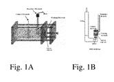
- FIGS. 1A and 1B illustrate half cell designs for measuring electrochemical properties.
- FIG. 2 shows specific capacitance as a function of CV cycle number for CNT electrodes.
- FIG. 3 illustrates the normalized capacitance at increasing voltage scan rates for two commercial capacitors and a capacitor of the invention.
- FIG. 4 is an FTIR transmission spectrum of a sample prepared according to the description in Yoon et al. dried overnight at 50° C.
- the x-axis of the spectrum is expressed in the conventional units of cm ⁇ 1 .
- FIG. 5 FTIR transmission spectrum of a sample prepared according to the description in Yoon et al. dried at 250° C. for 2 hours.
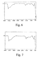
- FIG. 6 FTIR transmission spectrum of Ni2Co-MWNT as made.
- FIG. 7 FTIR transmission spectrum of Ni2Co-MWNT dried at 250° C. for 2 hours.
- FIG. 8 FTIR transmission spectra of Yoon et al. (top) and Ni2Co-MWNT (bottom), each dried for 2 hours at 250° C.
- FIG. 9 illustrates the specific capacitance of Ni2Co electrodes.
- FIG. 10 illustrates the cycling stability of Ni2Co electrodes.
- FIG. 11 illustrates the relation between specific capacitance and current density for Ni2Co electrodes.
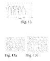
- FIG. 12 shows full-cell testing of metal oxide electrodes.
- FIG. 13 a shows full-cell testing at 4 A/g.
- FIG. 13 b shows full-cell testing at 20 A/g.
- Solid state electrodes for supercapacitors can be formed, for example, from oxides, hydroxides, sulfides, phosphates (or combinations thereof) of the transition metals cobalt and nickel in a composite material comprising a conductive material such as CNT and/or carbon black.
- the composite material typically comprises an amorphous phase and may also comprise a crystalline phase (x-ray diffraction is a technique that can be used to characterize the crystallinity of the material).
- the material should contain hydroxyls (as can be seen by IR spectroscopy).
- a preferred electrode of the present invention comprises oxides of Ni and Co having a Ni and Co in a molar ratio in the range of 0.5 to 6, more preferably a molar ratio in the range of 4 to 1, and in some embodiments, a molar ratio of 4 to 2.
- additional transition metal elements may also be present in the metal oxide; for example, Fe, Mn, or a combination of Fe and Mn.
- the transition metals in the electrode consist essentially of, or consist of, nickel and cobalt.
- the electrode materials may consist essentially of, or consist of, Ni—Co oxide particles, a conductive carbonaceous material, and a binder.
- the electrodes typically contain carbon as the conductive phase.
- Carbon materials are well known, and a variety of carbon particles may be used in the electrodes.
- the carbon material comprises carbon nanotubes (CNTs), in some embodiments at least 5 weight % CNTs as a percent of the mass of the electrode.
- the electrode comprises 40 to 90 weight % metal oxide particles (preferably nanoparticles) and 10 to 60 weight % carbon.
- the electrode comprises 65 to 90 weight % metal oxide particles (preferably nanoparticles) and 10 to 30 weight % carbon.
- the relative weights of carbon and metal oxide can be determined by removing the carbon such as by combustion.
- the electrodes may be characterized by a superior performance when substituting CNTs for carbon as the conductive component.
- binders are added in order to form the electrode in a desired shape and adhere the electrode to the current collector.
- Binders for making electrodes are known.
- Nonlimiting examples of binders include: PTFE, Nafion, Epoxy resin, Polyvinylidene fluoride (PVDF), Polyvinylidene fluoride-hexafluoropropylene (PVDF-HEP), ZrO 2 , and TiO 2 . Since binders reduce conductivity, when binders are present, it is preferred to keep them at a level of 5 mass% or less of the electrode's mass. For purposes of the present invention, mass % calculations do not include the mass of the collector.
- the composite material is directly deposited on a collector without any support material; for example, without a metal foam support.
- the collector is a flat plate.
- a supercapacitor also includes an aqueous or nonaqueous electrolyte.
- nonaqueous solvents for electrolytes include propylene carbonate (PC), ethylene carbonate (EC), dimethyl carbonate (DMC), diethyl carbonate (DEC), 1,2-dimethoxyethane (DME), 1,2-diethoxyethane (DEE), and blends of more than one non-aqueous solvent.
- electrolytes further comprise a material which readily separates into positively and negatively charged species. This material is commonly a salt.
- the salts preferably contain Li ions and counter ions such as PF 6 ⁇ , BF 4 ⁇ .
- this material may any material that readily separates into positively and negatively charged groups, such as KCl, KOH or LiOH.
- the electrolyte comprises 10-30% ethylene carbonate and 70-90% propylene carbonate. In some preferred embodiments, the carbonate solution comprises 15-25% ethylene carbonate and 75-85% propylene carbonate. In some preferred embodiments, the electrolyte comprises aqueous KOH. The electrolyte can be used in conjunction with electrodes containing a metal oxide, preferably mixed with carbon.
- the electrodes may be characterized by any of the properties described in the examples. For example, a specific capacitance (or, alternatively, total capacitance) of the same level or greater than that shown in the examples.
- the electrodes may be characterized by a higher capacitance value when composed of multiple layers of the mixed NiCo oxide/carbon/binder composite rather than a single layer of NiCo oxide/carbon/binder composite.
- the electrode may be made from two separate depositions of the same composition.
- the electrode comprises at least two layers that have different compositions.
- the compositions can differ by the relative amounts of binder, carbon, Nickel and Cobalt, Ni/Co ratio, and combinations of these.
- the electrodes may also be characterized by a higher capacitance value when composed of multiple layers of the mixed NiCo oxide/carbon/binder composite wherein a denser layer of the composite is deposited closer to the current collector, and/or wherein the first layer (nearer the collector) is more conductive than the second layer (further from the collector).
- the method of making the electrodes may be characterized by a higher capacitance value when subjected to a step of drying at room temperature.
- drying is conducted for at least 5 hours, or preferably at least 10 hours, or more preferably at least 20 hours.
- drying is conducted in air or in a humid environment.
- the electrodes are made by a process including an air drying step of 5 to 30 hours.
- the electrodes are made with only one drying step.
- drying is conducted a temperature of 80° C. or less, more preferably 50° C. or less, and still more preferably 30° C. or less.
- the method of making the electrodes may further be characterized by a higher capacitance value when subjected to a first step of vacuum drying followed by a second step of drying.
- the vacuum drying step is at least 5 minutes, more preferably at least 10 minutes, or at least 30 minutes. In some embodiments, vacuum drying is conducted for 5 minutes to an hour.
- the electrodes can be made using mixed metal oxides that are obtained by the sol-gel method to obtain a xerogel or aerogel which can then be ground into a powder and incorporated into an electrode.
- the mixed metal oxides can be made by a hydrolysis method.
- epoxides are reacted with the metal compound(s) to form a gel.
- the electrodes may be made at a temperature of below 50° C., in some embodiments the electrodes can be made at a temperature of 30° C. or less. In some preferred embodiments, the electrode is made by combining components at a temperature between ⁇ 100° C. and 30° C., and in some preferred embodiments between 0° C. and room temperature.
- the mixed metal oxides are preferably not heated above 250° C., more preferably not heated above 200° C., even more preferably not heated above 100° C., in some embodiments not heated above 50° C., and in some embodiments not heated above 30° C. In some other embodiments the mixed metal oxides are not heated above room temperature for the entire synthesis.
- the electrodes are preferably made in a process that does not include a calcination step.
- a preferred electrode of the present invention is characterized, as is shown in the examples, by a better performance at high voltage scan rates than the prior art, including higher specific capacitance values.
- the electrodes may also be characterized by a specific capacitance as a function of mass per surface area. It is well known in the literature that the specific capacitance can decrease with increasing thickness of the active layer. One method to obtain high specific capacitance is then to use a very thin layer of the active material. However, for most applications, this approach increases the amount of area needed to achieve a certain level of total capacitance beyond what is practical. Therefore, specifying the specific capacitance in terms of mass per unit area ensures the measurement is performed in a realistic environment.
- FIG. 1 shows a half-cell configuration used for measuring the capacitance of the electrodes.
- the specific capacitance is the total capacitance divided by the mass of the electrode, and so has units of F/g.
- the specific capacitance is often reported in the literature, as a measure of how effectively charge is being stored in or adjacent to the electrode.
- the total capacitance is of the most interest, as a measure of the value of the material for commercial applications.
- the particles are expected to have a high degree of hydroxide nature, as the drying occurs at a temperature below that normally needed to completely convert the hydroxide to oxide.
- oxides will be referred to generically as oxides throughout the text. In cases where the material is labeled with elements and numbers, such as Ni2Co, this indicates the oxide was formed at a nominal starting molar ratio of two Ni to one Co. Representative synthesis methods for the oxides are included below.
- NiCl2*6H2O 0.185 gram of NiCl2*6H2O, 0.093 gram of CoCl2*6H2O were dissolved in 2 gram of ethanol.
- 0.036 gram of CNT was added and the solution was ultrasonicated for 30 minutes.
- 1 gram of propylene oxide was added into the dispersed CNT solution under stirring. The solution was left sealed overnight and then dried at 50° C. in air.
- Metal oxides can be prepared by hydrolysis; for example by combining a metal-containing aqueous solution with a hydroxide solution. The addition of a hydroxide solution causes precipitation of a metal oxide.
- Electrodes for testing were fabricated using two procedures:
- the filter disc is used to ensure the electrode stays in place in the test cell.
- the filter disk has sufficient porosity that it should not alter the diffusion of charge or electrolyte.
- conductive media including acetylene black (AB), Ketjen black (KB), carbon nanotubes (CNT), multi-wall carbon nanotubes (MWNT), polypyrrole doped onto TiO 2 , and polypyrrole mixed with carbon black.
- AB acetylene black
- KB Ketjen black
- CNT carbon nanotubes
- MWNT multi-wall carbon nanotubes
- polypyrrole doped onto TiO 2 Several different conductive media were used, including acetylene black (AB), Ketjen black (KB), carbon nanotubes (CNT), multi-wall carbon nanotubes (MWNT), polypyrrole doped onto TiO 2 , and polypyrrole mixed with carbon black.
- the active area of the Ni current collectors used for aqueous measurements is approximately 1 cm 2
- the active area of the stainless steel collectors used for all non-aqueous measurements is approximately 1.12 cm 2 .
- the electrodes were composed of 95% CNT and 5% binder.
- the electrodes were tested under galvanic cycling conditions, at a current of 4 A/g. After transient effects, the specific capacitance of the electrodes was about 50 F/g.
- Electrodes were fabricated (Method A) with Ni2Co-CNT(25%) in the normal manner, then the specific capacitance was measured, and compared with two commercial double layer capacitor devices that were purchased and tested similarly. Electrochemical measurements were performed using a half-cell testing configuration in 1M KOH.
- FIG. 3 shows the normalized specific capacitance as a function of voltage scan rate. It can be clearly seen that, surprisingly, the inventive electrode composition demonstrates superior performance at high voltage scan rates.
- the inventive compositions can be characterized by the performance at high scan rates; for example, a performance as least as good as that shown in FIG. 3 .
- the electrodes preferably have a normalized capacitance of at least 0.5 (or at least 0.7, or in the range of 0.5 to about 0.8) at an average voltage scan rate of 100 mV/s, more preferably at an average voltage scan rate of 200 mV/s, and still more preferably at an average voltage scan rate of 300 mV/s.
- Electrodes were fabricated (Method A) with Ni2Co-MWNT(25%) in the normal manner, and then dried for 2 hours at 250° C. Infrared transmission spectra were collected, (scanning from 4000 cm ⁇ 1 and 500 cm ⁇ 1 ) before and after drying at 250° C. and compared with that of the prior art.
- FIGS. 4-5 show the FTIR spectra of samples prepared by a prior art method (Yoon et al.), and FIGS. 6-7 show that of the invention.
- the prior art's spectra does not possess the broad hydroxyl (—OH) stretch between 3750 cm ⁇ 1 and 3000 cm ⁇ 1 .
- the metal hydroxyl nature remains.
- the absorption in the CH stretch region in the spectrum of the prior art composition is believed to be due to contamination from an organic solvent.
- the invention can be characterized by absorbance in the IR spectrum of an OH stretch that is at least as intense as other absorptions in the region from 1000 to 4000 cm ⁇ 1 .
- FIG. 8 shows FTIR transmission spectra of both the prior art (top) and Ni2CO-MWNT compositions, each dried for 2 hours at 250° C.
- FIG. 9 shows the performance of these electrodes, both when fabricated then blended with AB, and when fabricated using oxide formed with the “in-situ” synthesis method.
- the electrodes were fabricated using 76% metal oxide, 19% additional AB, and 5% binder. These measurements were performed using a half-cell testing configuration in 1M KOH.
- Electrodes (Method A) with the Ni2Co materials of the previous example. These electrodes were tested for stability under galvanic cycling in 1M KOH at a current density of 4 A/g.
- FIG. 10 shows the specific capacitance as a function of cycling.
- the inventive compositions show excellent stability in aqueous electrolyte; preferably having less than 10% decrease in specific capacitance from cycles 2 to 10; more preferably 5% or less.
- Electrodes were fabricated (Method A) with Ni2Co-CNT(25%) in the normal manner, then the specific capacitance was measured at various current densities under galvanic cycling conditions. The testing was performed in a half-cell configuration, using 1M KOH as the electrolyte. The results are shown in FIG. 11 . Increasing the specific current from 4 A/g to 40 A/g resulted in less than a 40% decrease in specific capacitance. Thus, inventive compositions can be further characterized by their specific capacitance as a function of increasing current.
- the composites when applied to a collector and tested as described above,have a response to increasing current such that increasing current from 4 A/g to 10, 20, or more preferably 40 A/g reduces specific capacitance by less than 50%, more preferably by less than 40%, and still more preferably by less than 20%.
- the positive electrode (1.1 mg) was composed of Ni2Co1-CNT(25 wt %) composite (79.1 wt %), AB (18.6%), Nafion (2.3 wt %).
- the negative electrode (1.9 mg) was composed of FeOOH-CNT (25 wt %) composite (79.1 wt %), AB (18.6%), Nafion (2.3 wt %).
- Testing was performed in both 1M and 4M KOH, at a current density of 3 A/g, based on combined electrode mass.
- FIG. 12 shows the cell voltage as a function of time for both the 1M (dark lines) and 4M (light lines) tests. The charge/discharge times, and the corresponding capacitances are given in Table 2.
- the energy and power density can be calculated from this data, as shown in Table 3.
- a second full-cell test was performed, to determine the capacitance at different charge-discharge rates.
- the positive electrode 0.8 mg
- the negative electrode 0.9 mg
- the voltage as a function of time when tested at a current density of 4 A/g total electrode mass are shown in FIG. 13 a , while the results for testing at 20 A/g are given in FIG. 13 b .
- the energy and power density can be calculated from this data, and are given in Table 4.
- Method B We synthesized a mixed metal oxide Ni4Co, and fabricated electrodes (Method B) with this material.
- the oxide material was calcined at 450° C. to provide more reproducible specific capacitance.
- Table 5 shows the performance of these electrodes.
- the electrodes were fabricated using 75% Ni4Co, 25% AB, and 5% binder. These measurements were performed using a half-cell testing configuration in 1M KOH and at fast voltage scan rate of 20 mV/s for 5 cycles. Variation in the weight after drying is much lower using the calcined material, however the overall performance was decreased by the calcining.
- Ni4Co of two compositions, 75% Ni4Co/25% AB, and 90% Ni4Co/10% AB, both with 5% binder. Electrodes were fabricated according to Method B except modified as follows:
- a 1st layer of metal oxide paste (10 ⁇ L) was applied to the Nickel current collector, and the obtained uniform film dried in air for 4 hours, and the weight of the electrode material recorded. Then, a 2 nd layer of metal oxide paste (10 ⁇ L) was applied to the first layer, and the obtained uniform film dried in air for 6 hours, and the weight of the electrode material recorded.
- Capacitance measurements were performed using a half-cell testing configuration in 1M KOH and at fast voltage scan rate of 20 mV/s for 5 cycles. Table 6 shows the performance of these electrodes. The data indicates that multiple layers of metal oxide give higher capacitance than a single deposition layer, and capacitance is highest when the first layer is 90% Ni4Co1/10% AB. Also, the capacitance for the deposition of two layers of the same material gives higher capacitance than a single deposition of the same mass.
- Electrode B We synthesized a mixed metal oxide Ni4Co, and fabricated electrodes (Method B). The electrodes were dried in air for 1 hour before experiencing the various drying treatments prior to electrochemical characterization. Table 7 describes the various drying procedures, and shows the performance of these electrodes. The electrodes were fabricated using 75% Ni4Co, 25% AB, and 5% binder. These measurements were performed using a half-cell testing configuration in 1M KOH and at fast voltage scan rate of 20 mV/s for 5 cycles. The best capacitance is when the electrode is dried in air at room temperature overnight, and higher temperature heating reduced the performance. Only a slight difference in performance was observed with the presence of a vacuum, and electrodes dried for a short time of 1 or 2 hours were not reproducible and the capacitances may be very low. The general trend: the longer the drying time, the better the capacitance.
- the electrodes were fabricated (Method A) with the as-prepared Ni2Co-MWNT material and the Ni2Co-MWNT material that was calcined at 250° C. for 2 hours. These measurements were performed using a half-cell testing configuration in 1M KOH and at fast voltage scan rate of 20 mV/s for 5 cycles. Table 9 shows the capacitance results. The capacitance was greatly decreased by calcining the material.
Landscapes
- Engineering & Computer Science (AREA)
- Power Engineering (AREA)
- Chemical & Material Sciences (AREA)
- Materials Engineering (AREA)
- Microelectronics & Electronic Packaging (AREA)
- Crystallography & Structural Chemistry (AREA)
- Nanotechnology (AREA)
- Electric Double-Layer Capacitors Or The Like (AREA)
Abstract
Description
- This application claims the benefit of priority U.S. Provisional Patent Application Ser. No. 61/227,407, filed 21 Jul. 2009.
- Conventionally, electrical power has usually been stored in batteries. Another device for storing energy is a capacitor, and more recently the so-called supercapacitor. Very substantial efforts have been made to develop improved capacitors for storing electrical energy.
- The requirement for capacitance is the ability to separate charge at a specified potential. The prototypical capacitor consists of two metal plates, with a potential difference between the plates. In the charged state, one plate will have a net positive charge, the other a net negative charge. The capacitance can be determined from the area of the plates and the separation between the plates. Placing a solid dielectric material between the plates increases the capacitance, as the same potential difference between the plates leads to larger net charge on each plate.
- Recent developments in capacitor technology have led to replacement of the metal plates with high surface area conductive materials, such as carbon, and replacement of the solid dielectric with a liquid electrolyte. In case of carbon electrodes, the capacitance arises from the double layer mechanism, where the ions in the electrolyte move adjacent to the electrode surface. In this case, the capacitance increases due to two factors, the increase in the area of the electrode due to the porosity, and the decrease in the charge separation distance.
- The recent developments in synthesis of high surface area materials have also led to the development of capacitors based on a second mechanism, the so-called faradaic capacitors. The faradaic capacitors are composed of a solid state electrode with a liquid electrolyte. The operation principle of these capacitors is based on reversible reactions at the interface at certain potential. There are different characteristics of the second type of capacitors; the charge transfer reaction occurs at the interface of the outer porous layer, the substrate (current collector) is a different material than the external layer. The ions are integrated in the structure of the high surface area material (commonly an oxide or nitride) by reacting either by substitution or by integration of the ion within the structure of the material. To cite just one example, see Piao et al. “Intercalation of Lithium Ions into Graphite Electrodes studied by AC Impedance measurements,” J. Electrochem Soc. 146, 2794-2798 (1999). The stability will depend on the reversibility of this reaction (or process). If the reduction or oxidation process consumes more species than the reversible reaction, or if there is another species formed at the surface, the reversibility is modified.
- Recently, a third type of capacitor, the “hybrid” capacitor has also been reported. In this capacitor, both the double-layer and the faradaic mechanism are used, to provide enhanced capacitance, and to take advantage of operational advantages of each mechanism.
- A liquid electrolyte is either aqueous, with a high concentration of acid, base, or salt, or non-aqueous with a salt dissolved in an organic or inorganic solvent. There are a wide variety of solvents and salts available for such use, offering specific advantages depending on the application being considered (e.g., low temperature vs. high temperature). Ionic liquids based on the imidazolium cation have recently received attention as nonaqueous electrolytes in various electrochemical devices (Koch et al., J. Electrochem. Soc. 143:155, 1996). These electrolytes have significant advantages compared to the numerous quaternary onium salts that have been previously investigated for use in carbon double-layer capacitor.
- Electrochemical capacitors based on nonaqueous electrolytes offer greater electrochemical stability (up to 4 V) compared to aqueous systems (limited to approximately 1V), thereby providing greater energy storage (E=½CV2). However, due to the lower conductivity of nonaqueous electrolytes compared to aqueous systems, lower power capabilities are observed. In addition, with the porous materials used in electrochemical capacitors, the high viscosity typically associated with the high dielectric constant solvents used in nonaqueous electrolytes is detrimental to conductivity in porous electrodes. Furthermore, the lower ion concentrations typically obtained with nonaqueous electrolytes result in increased electrolyte volume requirements for packaged devices.
- A solid state electrode can be composed of a nanoporous transition metal compound placed on a high surface area conductive medium, such as carbon black, or carbon nanotube (CNT) films, combined with a binder to ensure physical integrity. If the ions move into the transition metal compound, the capacitance mechanism is faradaic, or possibly hybrid, while if the ions do not enter the transition metal compound the mechanism is purely double layer.
- There are numerous reports in the prior art describing methods of forming electrodes from composites of carbon and metal oxides or mixed metal oxides. For example, Leela Mohana Reddy et al. in “Asymmetric Flexible Supercapacitor Stack”, Nanoscale Research Letters, Volume 3, Number 4/April, 2008, describe the preparation of a supercapacitor with metal oxide and multiwalled carbon nanotubes (MWNTs) composites synthesized by a sol-gel method. Fan et al. in “Preparation and capacitive properties of cobalt-nickel oxides/carbon nanotube composites”, Electrochim. Acta, 52 (2007) 2959, reported the preparation of nickel-cobalt oxides/carbon nanotube (CNT) composites. Kuan-Xin et al. in “Electrodeposition of Nickel and Cobalt Mixed Oxide/Carbon Nanotube Thin Films and Their Charge Storage Properties,” J. Electrochem. Soc., 153, A1568-A1574 (2006) reported a method of electrochemically depositing a mixed metal oxide on a film of carbon nanotubes.
- In U.S. Pat. No. 5,079,674, Malaspina describes a composite supercapacitor made from metal oxide and carbon black. In his method, carbon black is added to a solution of the metal salt, converted to its hydroxide or oxide, a fluorocarbon polymer added, and the resulting material is converted to sheet form and dried in an oven at a temperature of between about 80° C. and 125° C. The resulting sheet material is laminated to a separator, cut into a desired shape, and assembled to form a supercapacitor. Malaspina does not provide specific examples or capacitance data; and there is no description of the effect of synthetic conditions on material properties.
- Yoon et al. in “CoNi Oxide/Carbon-Nanofiber Composite Electrodes for Supercapacitors”, Int. J. Electrochem. Sci., 3 (2008) 1340-1347, report the synthesis of cobalt-nickel oxide/VGCF (vapor grown carbon fiber) composites for super capacitors. In this method, a weighed quantity of VGCF was added to a cobalt-nickel nitrate solution, sonicated for 1 hour and then dropped onto a nickel foam and annealed at 250° C. for 2 hours. Yoon et al. reported that the cobalt-nickel oxide/VGCF composite electrode exhibited a peak specific capacitance value of 1271 Fg−1 at a scan rate of 5 mV·s−1, however neither the weight of the nickel foam substrate nor the weight of the VGCF was included in the specific capacitance calculations. The 3-dimensional nickel foam substrate has advantages over the more typical 2-dimensional metallic foil type of current collector, including providing a very high surface area for greater capacitance, but has disadvantages due to its cost, large volume and weight.
- Despite extensive research and development, there remains a need for improved capacitors for the storage of energy.
- In a first aspect, the invention provides a capacitor comprising: an electrode, and wherein the electrode comprises: Ni and Co in a molar ratio of greater than 0.5:1; and further possessing one or more of the following characteristics:
- (a) the electrode comprises a specific capacitance of at least 450 F/g·cm2 if measured at a voltage scan rate of 20 mV/s in 1M KOH aqueous electrolyte; or
- (b) the electrode comprises a first specific capacitance when measured at 50 mV/s and a second specific capacitance when measured at 20 mV/s; and further wherein the ratio of the first specific capacitance to the second specific capacitance is at least 0.6; or
- (c) absorbance in the IR spectrum of an OH stretch that is at least as intense as other absorptions in the region from 1000 to 4000 cm−1.
- The surface area of the electrode (represented by the unit “cm2”) in the above-described specific capacitance is the macroscopic area of the electrode. For example, for an electrode disposed on a flat 1 cm2×1 cm2 collector, the surface area is 1 cm2. For an electrode composition disposed on a metallic foam, the surface area would be the surface area of the metallic foam. Preferably, the electrode has a mass of at least 0.5 mg, more preferably at least 0.8 mg. In preferred embodiments, the electrode has a mass per surface area of at least 0.5 mg/cm2, more preferably at least 0.8 mg/cm2.
- Preferably the capacitor has a first specific capacitance when measured at 50 mV/s and a second specific capacitance when measured at 20 mV/s; and further wherein the ratio of the first specific capacitance to the second specific capacitance is at least 0.6; more preferably at least 0.8, and in some embodiments, in the range of 0.9 to 1.0. Alternatively, the electrodes preferably have a normalized capacitance of at least 0.5 (or at least 0.7, or in the range of 0.5 to about 0.8) at an average voltage scan rate of 100 mV/s, more preferably at an average voltage scan rate of 200 mV/s, and still more preferably at an average voltage scan rate of 300 mV/s.
- Preferably, the the electrode has a mass in the range of 0.1 to 2 mg. Also, preferably, the electrode comprises a specific capacitance of at least 550 F/g if measured at a voltage scan rate of 20 mV/s in 1M KOH aqueous electrolyte. Since it has been surprisingly discovered that electrodes comprising carbon nanotubes preform better than other forms of carbon, the electrode preferably comprises at least 5 weight % carbon nanotubes.
- In some preferred embodiments, the electrode comprises a current collector, and there is a denser layer of the composite deposited closer to the current collector, and the denser layer is more conductive than a second layer of the composite that is further from the current collector.
- The invention further provides a capacitor comprising any of the electrode materials described herein; an electrolyte; a second electrode; and a circuit that can form an electrical pathway between the first electrode and the second electrode. The electrolyte can be a nonaqueous liquid or an aqueous liquid. The first and second electrodes can be the same or can be composed of two distinct metal oxides.
- The invention also includes a solar energy system comprising the capacitor of any of claims 15-17 and a photovoltaic cell.
- In another aspect, the invention provides a method of making an electrode, comprising: forming a composition comprising Ni and Co in a molar ratio of at least 0.5:1; reacting the composition to form a gel; drying the gel to obtain a powder comprising Ni and Co in a molar ratio of 0.5:1 to 4:1; and compacting the powder to form an electrode.
- In a further aspect, the invention provides a method of making an electrode, comprising: forming a composition comprising Ni and Co in a molar ratio of at least 0.5:1 wherein the temperature of the process never exceeds 200° C., more preferably the temperature of the process never exceeds 50° C.
- In another aspect, the invention provides a method of storing energy comprising: applying a potential to the capacitor described herein and removing the potential; and wherein, after the potential is removed, an electrical potential persists between the electrodes.
- The inventive capacitors are especially useful for rapidly storing or providing energy. Examples include such applications as storing braking energy from cars or trains, capturing energy from lightning strikes, accelerating vehicles or other objects, or providing rapid energy spikes for electrical or electromagnetic devices. The inventive capacitors are especially useful for storing energy from renewable energy sources such as solar, wind, and tidal. In these systems, charge is stored during periods of high energy production, and can be used when little or no energy is being collected. The capacitor may have parallel plates. Alternatively, the capacitor can be in the form, for example, where the electrodes and separators can be alternately stacked, wound into a roll, and electrolyte poured in, then sealed to form a supercapacitor energy storage device.
- The “weight %” (weight percentage composition) of a compound, refers to its % by weight measured at 20° C. For example, a composite electrode made by mixing 4 mg of Ni2Co oxide and 6 mg of carbon nanotubes (at 20° C.) would be 40 weight % Ni2Co oxide and 60 weight % carbon nanotubes.
- For purposes of the present invention, a “capacitor” (or supercapacitor) that includes two electrodes that are typically separated by a separator. Note that the electrodes may include any of the electrodes described herein. The capacitors of this invention may store energy via a double layer mechanism and may also incorporate energy storage through the intercalation of charge into the electrode materials. Note further that, although a separator is typically desirable for structural stability, in some highly rigid structures it is possible to omit the separator. The two electrodes are also connected, or connectable, to an external circuit that is the energy source during charging, and is where useful work can be done during discharge of the capacitor.
- “Capacitance” (see also “specific capacitance” below) is the ability of a body to hold an electrical charge. It is also a measure of the amount of electrical energy stored (or separated) for a given electric potential. A common form of energy storage device is a parallel-plate capacitor, as described above. In a parallel plate capacitor, capacitance is directly proportional to the surface area of the conductor plates and inversely proportional to the separation distance between the plates. If the charges on the plates are +Q and −Q, and V gives the voltage between the plates, then the capacitance (C) is given by: C=Q/V
- The SI unit of capacitance is the farad (F); 1 farad is 1 coulomb per volt.
- A “Current collector” is a well-known term that refers to a conductive component of a capacitor, and is used to lead electrical power away from the electrodes.
- An “Electrical current” is a flow of electric charge (a phenomenon) or the rate of flow of electric charge (a quantity). This flowing electric charge is typically carried by moving electrons, in a conductor such as wire; in an electrolyte, it is instead carried by ions, and, in a plasma, by both.
- An “Electrical circuit” is an interconnection of electrical elements such as resistors, capacitors, voltage sources, current sources, and switches that has a closed loop, giving a return path for the current.
- An “Electrode” is a well-known term that refers to a conductive component of a capacitor that contacts the electrolyte.
- “Electrolyte” is a composition comprising one or more ionic species and a medium through which ions can move. In some preferred embodiments, the electrolyte comprises an aqueous medium containing dissolved ions. In other preferred embodiments, the electrolyte comprises a non-aqueous liquid, preferably containing less than 100 ppm water, and containing a dissolved salt.
- “Intercalating” refers to the reversible inclusion of lithium into an electrode.
- “Ionic species” means an ion, or a compound that forms an ion as part of an electrolyte (i.e., forms an ion under conditions in the capacitor; for example, a carboxylic acid can be converted to an ion in the appropriate solvent).
- “Lithium salts” are well known materials for use in electrolytes and include compounds such as LiN(SO2CF3)2, LiBF4 or LiPF6. Alkali hydroxides are well known materials for use in aqueous electrolytes, and include compounds such as LiOH and KOH.
- “Metal oxides” comprise transition metal atoms connected by bridging oxygen atoms. Metal oxide particles may also contain other atoms such as B, N, C, Al, Zn, etc. Metal oxides will often also comprise hydroxyl groups which diminish in concentration with heating. In some preferred embodiments, metal oxides consist essentially of transition metals (or metal), oxygen, and, optionally, H in the form of hydroxides.
- “Mixed metal oxides” are metal oxides comprising at least two different transition metals. The inventive materials typically comprise an amorphous phase and are believed to contain Ni and Co atoms bridged by oxygen (Ni—O—Co) may contain bridging or terminal hydroxides.
- “Nanoparticles” are particles in the size range of 1 to 1000 nm, preferably in the range of 1 to 100 nm.
- “Potential” or the “voltage” between two points is a short name for the electrical force that would drive an electric current between those points. Specifically, voltage is equal to energy per unit charge. In the case of static electric fields, the voltage between two points is equal to the electrical potential difference between those points.
- A “Separator” is a porous sheet placed between the positive and negative electrodes in an electrolyte. Its function is to prevent physical contact of the positive and negative electrodes while serving as an electrolyte reservoir to enable free ionic transport. Typically, the separator is a polymeric or ceramic microporous membrane or a nonwoven cloth. The microporous membranes are preferably 25 μm or less in thickness and have an average pore size of 1 μm or less (volume average).
- A “Solar energy system” is a system harnessing the energy from the sun. For our purposes it comprises a capacitor and a photovoltaic cell.
- “Specific capacitance” is the total capacitance divided by the mass of the electrode, and so has units of Farads per gram (F/g). The specific capacitance is often reported in the literature, as a measure of how effectively charge is being stored in or adjacent to the electrode. The total capacitance is of the most interest as a measure of the value of the material for commercial applications. All specific capacitance values reported in this document will be based on the total mass of the electrode, including the binder and the conductive component.
-
FIGS. 1A and 1B illustrate half cell designs for measuring electrochemical properties. -
FIG. 2 shows specific capacitance as a function of CV cycle number for CNT electrodes. -
FIG. 3 illustrates the normalized capacitance at increasing voltage scan rates for two commercial capacitors and a capacitor of the invention. -
FIG. 4 is an FTIR transmission spectrum of a sample prepared according to the description in Yoon et al. dried overnight at 50° C. The x-axis of the spectrum is expressed in the conventional units of cm−1. -
FIG. 5 FTIR transmission spectrum of a sample prepared according to the description in Yoon et al. dried at 250° C. for 2 hours. -
FIG. 6 FTIR transmission spectrum of Ni2Co-MWNT as made. -
FIG. 7 FTIR transmission spectrum of Ni2Co-MWNT dried at 250° C. for 2 hours. -
FIG. 8 FTIR transmission spectra of Yoon et al. (top) and Ni2Co-MWNT (bottom), each dried for 2 hours at 250° C. -
FIG. 9 illustrates the specific capacitance of Ni2Co electrodes. -
FIG. 10 illustrates the cycling stability of Ni2Co electrodes. -
FIG. 11 illustrates the relation between specific capacitance and current density for Ni2Co electrodes. -
FIG. 12 shows full-cell testing of metal oxide electrodes. -
FIG. 13 a shows full-cell testing at 4 A/g. -
FIG. 13 b shows full-cell testing at 20 A/g. - Solid state electrodes for supercapacitors can be formed, for example, from oxides, hydroxides, sulfides, phosphates (or combinations thereof) of the transition metals cobalt and nickel in a composite material comprising a conductive material such as CNT and/or carbon black. The composite material typically comprises an amorphous phase and may also comprise a crystalline phase (x-ray diffraction is a technique that can be used to characterize the crystallinity of the material). For superior properties, the material should contain hydroxyls (as can be seen by IR spectroscopy).
- A preferred electrode of the present invention comprises oxides of Ni and Co having a Ni and Co in a molar ratio in the range of 0.5 to 6, more preferably a molar ratio in the range of 4 to 1, and in some embodiments, a molar ratio of 4 to 2. In some embodiments, additional transition metal elements may also be present in the metal oxide; for example, Fe, Mn, or a combination of Fe and Mn. In other embodiments, the transition metals in the electrode consist essentially of, or consist of, nickel and cobalt. In some embodiments, the electrode materials may consist essentially of, or consist of, Ni—Co oxide particles, a conductive carbonaceous material, and a binder.
- In addition to the Ni—Co oxide in particle form, the electrodes typically contain carbon as the conductive phase. Carbon materials are well known, and a variety of carbon particles may be used in the electrodes. In some preferred embodiments, the carbon material comprises carbon nanotubes (CNTs), in some embodiments at least 5 weight % CNTs as a percent of the mass of the electrode. In some preferred embodiments, the electrode comprises 40 to 90 weight % metal oxide particles (preferably nanoparticles) and 10 to 60 weight % carbon. In some embodiments, the electrode comprises 65 to 90 weight % metal oxide particles (preferably nanoparticles) and 10 to 30 weight % carbon. For analyzing a material of unknown synthetic origin, the relative weights of carbon and metal oxide can be determined by removing the carbon such as by combustion. The electrodes may be characterized by a superior performance when substituting CNTs for carbon as the conductive component.
- Typically, one or more binders are added in order to form the electrode in a desired shape and adhere the electrode to the current collector. Binders for making electrodes are known. Nonlimiting examples of binders include: PTFE, Nafion, Epoxy resin, Polyvinylidene fluoride (PVDF), Polyvinylidene fluoride-hexafluoropropylene (PVDF-HEP), ZrO2, and TiO2. Since binders reduce conductivity, when binders are present, it is preferred to keep them at a level of 5 mass% or less of the electrode's mass. For purposes of the present invention, mass % calculations do not include the mass of the collector. In some preferred embodiments, the composite material is directly deposited on a collector without any support material; for example, without a metal foam support. In some preferred embodiments, the collector is a flat plate.
- A supercapacitor also includes an aqueous or nonaqueous electrolyte. Examples of nonaqueous solvents for electrolytes include propylene carbonate (PC), ethylene carbonate (EC), dimethyl carbonate (DMC), diethyl carbonate (DEC), 1,2-dimethoxyethane (DME), 1,2-diethoxyethane (DEE), and blends of more than one non-aqueous solvent. As is known in the art, electrolytes further comprise a material which readily separates into positively and negatively charged species. This material is commonly a salt. In the present invention, the salts preferably contain Li ions and counter ions such as PF6 −, BF4 −. For aqueous electrolytes, this material may any material that readily separates into positively and negatively charged groups, such as KCl, KOH or LiOH.
- In some preferred embodiments, the electrolyte comprises 10-30% ethylene carbonate and 70-90% propylene carbonate. In some preferred embodiments, the carbonate solution comprises 15-25% ethylene carbonate and 75-85% propylene carbonate. In some preferred embodiments, the electrolyte comprises aqueous KOH. The electrolyte can be used in conjunction with electrodes containing a metal oxide, preferably mixed with carbon.
- The electrodes may be characterized by any of the properties described in the examples. For example, a specific capacitance (or, alternatively, total capacitance) of the same level or greater than that shown in the examples.
- The electrodes may be characterized by a higher capacitance value when composed of multiple layers of the mixed NiCo oxide/carbon/binder composite rather than a single layer of NiCo oxide/carbon/binder composite. In some embodiments, the electrode may be made from two separate depositions of the same composition. In some other preferred embodiments, the electrode comprises at least two layers that have different compositions. The compositions can differ by the relative amounts of binder, carbon, Nickel and Cobalt, Ni/Co ratio, and combinations of these. The electrodes may also be characterized by a higher capacitance value when composed of multiple layers of the mixed NiCo oxide/carbon/binder composite wherein a denser layer of the composite is deposited closer to the current collector, and/or wherein the first layer (nearer the collector) is more conductive than the second layer (further from the collector).
- In some embodiments, the method of making the electrodes may be characterized by a higher capacitance value when subjected to a step of drying at room temperature. Preferably, drying is conducted for at least 5 hours, or preferably at least 10 hours, or more preferably at least 20 hours. In some preferred embodiments, drying is conducted in air or in a humid environment. In some embodiments, the electrodes are made by a process including an air drying step of 5 to 30 hours. Preferably, the electrodes are made with only one drying step. Preferably, drying is conducted a temperature of 80° C. or less, more preferably 50° C. or less, and still more preferably 30° C. or less. The method of making the electrodes may further be characterized by a higher capacitance value when subjected to a first step of vacuum drying followed by a second step of drying. Preferably, the vacuum drying step is at least 5 minutes, more preferably at least 10 minutes, or at least 30 minutes. In some embodiments, vacuum drying is conducted for 5 minutes to an hour.
- The electrodes can be made using mixed metal oxides that are obtained by the sol-gel method to obtain a xerogel or aerogel which can then be ground into a powder and incorporated into an electrode. The mixed metal oxides can be made by a hydrolysis method. Alternatively, in some embodiments, epoxides are reacted with the metal compound(s) to form a gel.
- The electrodes may be made at a temperature of below 50° C., in some embodiments the electrodes can be made at a temperature of 30° C. or less. In some preferred embodiments, the electrode is made by combining components at a temperature between −100° C. and 30° C., and in some preferred embodiments between 0° C. and room temperature.
- For the entire synthesis including all drying steps, the mixed metal oxides are preferably not heated above 250° C., more preferably not heated above 200° C., even more preferably not heated above 100° C., in some embodiments not heated above 50° C., and in some embodiments not heated above 30° C. In some other embodiments the mixed metal oxides are not heated above room temperature for the entire synthesis. Thus, the electrodes are preferably made in a process that does not include a calcination step.
- A preferred electrode of the present invention, is characterized, as is shown in the examples, by a better performance at high voltage scan rates than the prior art, including higher specific capacitance values.
- The electrodes may also be characterized by a specific capacitance as a function of mass per surface area. It is well known in the literature that the specific capacitance can decrease with increasing thickness of the active layer. One method to obtain high specific capacitance is then to use a very thin layer of the active material. However, for most applications, this approach increases the amount of area needed to achieve a certain level of total capacitance beyond what is practical. Therefore, specifying the specific capacitance in terms of mass per unit area ensures the measurement is performed in a realistic environment.
- The fabricated electrodes were characterized to determine their capacitance, voltage window, open circuit potential, and other parameters.
FIG. 1 shows a half-cell configuration used for measuring the capacitance of the electrodes. - The general sequence of experiments used to characterize the electrodes includes the following steps:
- Open circuit potential with time (1 h)
- Electrochemical Impedance Spectroscopy (10 mV amplitude) 10 KHz to 0.01 Hz
- Cyclic voltammetry (aqueous solutions 0.7V vs. SCE to −0.7 vs. SCE)
- Analysis of the results (currents, voltage and capacitance)
The values of specific capacitance reported here are measured using cyclic voltammetry. Although some electrodes have been characterized for 100 voltage cycles or more, the reported capacitance is routinely determined from the second voltage cycle. In the present invention, specific capacitance can be determined for the second voltage cycle; in some embodiments, after 10 voltage cycles or 100 voltage cycles. - Two types of capacitance values will be reported here, the total capacitance and the specific capacitance. The specific capacitance is the total capacitance divided by the mass of the electrode, and so has units of F/g. The specific capacitance is often reported in the literature, as a measure of how effectively charge is being stored in or adjacent to the electrode. The total capacitance is of the most interest, as a measure of the value of the material for commercial applications.
- Care must be exercised when comparing the data of this invention to data reported in the open literature. The common practice in the literature is to report the specific capacitance of metal oxide electrodes by dividing the measured capacitance by the mass of the metal oxide only. The largest capacitance values that are reported typically occur when the oxide is approximately 10% of the total electrode mass. For example, in 2006 J. Electrochem. Soc. pp. A1451, the authors present data for the capacitance of vanadium oxide deposited onto CNT films, when measured at a scan rate of 1 mV/sec, as shown in Table 1.
-
TABLE 1 Specific capacitance of V2O5 on CNT films taken from the literature. Capacitance using Vanadium Capacitance using % mass of V2O5 mass total electrode mass 8.9 wt % 1230 F/g 109.5 F/g 33.9 wt % 650 F/g 220.4 F/g 51.3 wt % 310 F/g 159 F/g - From Table 1, we see that the reported best value of 1230 F/g for the vanadium oxide capacitance is actually from the electrode with the lowest total capacitance. In many cases, the conductive component of the electrode will contribute double layer capacitance, which should also be accounted for. In cases where the transition metal compound is only 10% of the electrode mass, the double layer capacitance can be of the same order of magnitude as the faradaic component.
- To avoid these complications, all specific capacitance values reported in this document will be based on the total mass of the electrode, including the binder and the conductive component, but not including the mass of the collector (however, it would include a support material such as a foam, if present).
- Two approaches to synthesize metal nanoparticles are a hydrolysis process, or a xerogel process. In preferred cases, the particles are expected to have a high degree of hydroxide nature, as the drying occurs at a temperature below that normally needed to completely convert the hydroxide to oxide. These materials will be referred to generically as oxides throughout the text. In cases where the material is labeled with elements and numbers, such as Ni2Co, this indicates the oxide was formed at a nominal starting molar ratio of two Ni to one Co. Representative synthesis methods for the oxides are included below.
- Preparation of “in-situ” Ni2Co-CNT(15%) Mixed Oxide Xerogel
- 0.185 gram of NiCl2*6H2O, 0.093 gram of CoCl2*6H2O were dissolved in 2 gram of ethanol. To this solution, 0.036 gram of CNT was added and the solution was ultrasonicated for 30 minutes. 1 gram of propylene oxide was added into the dispersed CNT solution under stirring. The solution was left sealed overnight and then dried at 50° C. in air.
- 2.20 g FeCl3.6H2O, 1.85 g NiCl2.6H2O, and 0.59 g water were dissolved in 20 g ethanol. 10 g propylene oxide (PPO) was added quickly into the alcoholic solution under stirring with a gel forming in less than 16 minutes. The formed gel was aged with sealing for several days at room temperature. The solvent (ethanol and water) in the gel was exchanged with acetone at least three times (one day one time). The acetone exchanged gel was finally dried by supercritical CO2. Nickel-cobalt mixed oxide/hydroxide could be prepared in a similar fashion, starting with 1.85 g NiCl2.6H2O and CoCl2*6H2O 0.93 g.
- Metal oxides can be prepared by hydrolysis; for example by combining a metal-containing aqueous solution with a hydroxide solution. The addition of a hydroxide solution causes precipitation of a metal oxide.
- Electrodes for testing were fabricated using two procedures:
-
-
- The metal oxide was ground by hand to a fine powder.
- The conductive component (if used) was added to the oxide powder and ground again.
- Approximately 20 mg of the powder was added to a mortar, and then the appropriate amount of binder was added from a 5% in solvent mixture.
- Approximately 150 mg of 1-methyl-2-pyrroidinone (NMP) was added.
- The mixture was again ground to form a paste. The paste was then applied to the current collector substrate (stainless steel or Nickel).
- The metal oxide on stainless steel electrode was then heated for 1 hour at 100° C. until all solvents evaporated.
- A Nylon filter disc was then placed over the dried metal oxide electrode. The electrode/filter disc assembly was then placed in the electrochemical apparatus for measurement.
- The filter disc is used to ensure the electrode stays in place in the test cell. The filter disk has sufficient porosity that it should not alter the diffusion of charge or electrolyte.
-
-
- The metal oxide was ground by hand to a fine powder and calcined at 450° C.
- 70 mg Ni4Co1, 25 mg AB, and 109 μl 5 wt % Nafion were dispersed in 2 gram of tert-butyl alcohol.
- The mixture was ultrasonicated for 30 minutes and then stirred for overnight.
- The stirred paste was ultrasonicated for 30 minutes before depositing on Nickel current collector electrodes.
- For the deposition, 22 μL paste solution was taken out and dropped onto a Ni substrate.
- The obtained uniform film was dried in air for 2 hours and the weight of electrode material was recorded.
- The air-dried sample was then dried in a vacuum oven (˜20 psig at 100° F.) overnight.
- The electrode/filter disc assembly was then placed in the electrochemical apparatus for measurement.
- Several different conductive media were used, including acetylene black (AB), Ketjen black (KB), carbon nanotubes (CNT), multi-wall carbon nanotubes (MWNT), polypyrrole doped onto TiO2, and polypyrrole mixed with carbon black. The active area of the Ni current collectors used for aqueous measurements is approximately 1 cm2, while the active area of the stainless steel collectors used for all non-aqueous measurements is approximately 1.12 cm2.
- We show the specific capacitance for an electrode composed of carbon nanotubes and binder in
FIG. 2 . The electrodes were composed of 95% CNT and 5% binder. The electrodes were tested under galvanic cycling conditions, at a current of 4 A/g. After transient effects, the specific capacitance of the electrodes was about 50 F/g. - Electrodes were fabricated (Method A) with Ni2Co-CNT(25%) in the normal manner, then the specific capacitance was measured, and compared with two commercial double layer capacitor devices that were purchased and tested similarly. Electrochemical measurements were performed using a half-cell testing configuration in 1M KOH.
FIG. 3 shows the normalized specific capacitance as a function of voltage scan rate. It can be clearly seen that, surprisingly, the inventive electrode composition demonstrates superior performance at high voltage scan rates. The inventive compositions can be characterized by the performance at high scan rates; for example, a performance as least as good as that shown inFIG. 3 . The electrodes preferably have a normalized capacitance of at least 0.5 (or at least 0.7, or in the range of 0.5 to about 0.8) at an average voltage scan rate of 100 mV/s, more preferably at an average voltage scan rate of 200 mV/s, and still more preferably at an average voltage scan rate of 300 mV/s. - Electrodes were fabricated (Method A) with Ni2Co-MWNT(25%) in the normal manner, and then dried for 2 hours at 250° C. Infrared transmission spectra were collected, (scanning from 4000 cm−1 and 500 cm−1) before and after drying at 250° C. and compared with that of the prior art.
FIGS. 4-5 show the FTIR spectra of samples prepared by a prior art method (Yoon et al.), andFIGS. 6-7 show that of the invention. Comparing the FTIR spectra of the prior art and that of the invention, it can be seen that unlike the invention, the prior art's spectra does not possess the broad hydroxyl (—OH) stretch between 3750 cm−1 and 3000 cm−1. Thus indicating that the prior art has formed a pure metal oxide whereas in the inventive composition, the metal hydroxyl nature remains. The absorption in the CH stretch region in the spectrum of the prior art composition is believed to be due to contamination from an organic solvent. Thus, in preferred embodiments, the invention can be characterized by absorbance in the IR spectrum of an OH stretch that is at least as intense as other absorptions in the region from 1000 to 4000 cm−1. -
FIG. 8 shows FTIR transmission spectra of both the prior art (top) and Ni2CO-MWNT compositions, each dried for 2 hours at 250° C. - We synthesized a mixed metal oxide Ni2Co, and fabricated electrodes (Method A) with this material.
FIG. 9 shows the performance of these electrodes, both when fabricated then blended with AB, and when fabricated using oxide formed with the “in-situ” synthesis method. The electrodes were fabricated using 76% metal oxide, 19% additional AB, and 5% binder. These measurements were performed using a half-cell testing configuration in 1M KOH. - We fabricated electrodes (Method A) with the Ni2Co materials of the previous example. These electrodes were tested for stability under galvanic cycling in 1M KOH at a current density of 4 A/g.
FIG. 10 shows the specific capacitance as a function of cycling. Thus, the inventive compositions show excellent stability in aqueous electrolyte; preferably having less than 10% decrease in specific capacitance fromcycles 2 to 10; more preferably 5% or less. - Electrodes were fabricated (Method A) with Ni2Co-CNT(25%) in the normal manner, then the specific capacitance was measured at various current densities under galvanic cycling conditions. The testing was performed in a half-cell configuration, using 1M KOH as the electrolyte. The results are shown in
FIG. 11 . Increasing the specific current from 4 A/g to 40 A/g resulted in less than a 40% decrease in specific capacitance. Thus, inventive compositions can be further characterized by their specific capacitance as a function of increasing current. In preferred embodiments, the composites (when applied to a collector and tested as described above)have a response to increasing current such that increasing current from 4 A/g to 10, 20, or more preferably 40 A/g reduces specific capacitance by less than 50%, more preferably by less than 40%, and still more preferably by less than 20%. - Full-cell testing was performed, where metal oxide electrodes were used as both the anode and cathode. The positive electrode (1.1 mg) was composed of Ni2Co1-CNT(25 wt %) composite (79.1 wt %), AB (18.6%), Nafion (2.3 wt %). The negative electrode (1.9 mg) was composed of FeOOH-CNT (25 wt %) composite (79.1 wt %), AB (18.6%), Nafion (2.3 wt %). Testing was performed in both 1M and 4M KOH, at a current density of 3 A/g, based on combined electrode mass.
FIG. 12 shows the cell voltage as a function of time for both the 1M (dark lines) and 4M (light lines) tests. The charge/discharge times, and the corresponding capacitances are given in Table 2. -
TABLE 2 Performance of the full-cell capacitor KOH Cycle Charging Discharging Charging Discharging (M) (number) time (s) time (s) (F/g) (F/g) 1 2 87 80 56 54 4 2 108 109 72 72 - The energy and power density can be calculated from this data, as shown in Table 3.
-
TABLE 3 Performance of the full-cell capacitor Electrolyte Charge (2nd cycle) Discharge (2nd cycle) P (W/kg) 1M KOH 1.3*103 0.94*103 E(Wh/kg) 1M KOH 31 21 P (W/kg) 4M KOH 1.3*103 0.92*103 E(Wh/kg) 4M KOH 38 27 - A second full-cell test was performed, to determine the capacitance at different charge-discharge rates. The positive electrode (0.8 mg) was fabricated from Ni2Co1-CNT (25 wt %) and the negative electrode (0.9 mg) was fabricated from FeOOH-CNT (50 wt %). The voltage as a function of time when tested at a current density of 4 A/g total electrode mass are shown in
FIG. 13 a, while the results for testing at 20 A/g are given inFIG. 13 b. The energy and power density can be calculated from this data, and are given in Table 4. -
TABLE 4 Performance of the full-cell capacitor Specific current Charge (2nd cycle) Discharge (2nd cycle) P (W/kg) 4 A/g 5.13*103 3.33*103 E(Wh/kg) 4 A/g 42.6 26.4 P (W/kg) 20 A/g 27.5*103 15.8*103 E(Wh/kg) 20 A/g 36.6 18.0 - We synthesized a mixed metal oxide Ni4Co, and fabricated electrodes (Method B) with this material. In Method B, the oxide material was calcined at 450° C. to provide more reproducible specific capacitance. Table 5 shows the performance of these electrodes. The electrodes were fabricated using 75% Ni4Co, 25% AB, and 5% binder. These measurements were performed using a half-cell testing configuration in 1M KOH and at fast voltage scan rate of 20 mV/s for 5 cycles. Variation in the weight after drying is much lower using the calcined material, however the overall performance was decreased by the calcining.
-
TABLE 5 Electrode weight Sample number (mg) Scan (cycle) Capacitance (F/g) 52819-4-10 0.87 5th 252 52819-4-12 0.86 5th 283 52819-4-14 0.86 5th 224 52819-4-16 0.84 5th 323 52819-4-18 0.79 5th 324 52819-4-20 0.88 5th 301 Average 284 Standard deviation 36 or 13% 52819-5-1 0.83 5th 313 52819-5-2 0.83 5th 327 52819-5-3 0.78 5th 263 52819-5-4 0.72 5th 315 Average 304 Standard deviation: 24 or (8%) - We synthesized mixed metal oxides Ni4Co of two compositions, 75% Ni4Co/25% AB, and 90% Ni4Co/10% AB, both with 5% binder. Electrodes were fabricated according to Method B except modified as follows:
- A 1st layer of metal oxide paste (10 μL) was applied to the Nickel current collector, and the obtained uniform film dried in air for 4 hours, and the weight of the electrode material recorded. Then, a 2nd layer of metal oxide paste (10 μL) was applied to the first layer, and the obtained uniform film dried in air for 6 hours, and the weight of the electrode material recorded.
- The constructed electrode was then completed as for Method B. Capacitance measurements were performed using a half-cell testing configuration in 1M KOH and at fast voltage scan rate of 20 mV/s for 5 cycles. Table 6 shows the performance of these electrodes. The data indicates that multiple layers of metal oxide give higher capacitance than a single deposition layer, and capacitance is highest when the first layer is 90% Ni4Co1/10% AB. Also, the capacitance for the deposition of two layers of the same material gives higher capacitance than a single deposition of the same mass.
-
TABLE 6 Net electrode Net electrode Sample weight (mg) weight (mg) Total net Capacitance number 1st layer at 4 hours 2nd layer at 10 hours weight (mg)* (F/g) 52819-10-1 75% Ni4Co1 0.49 75% Ni4Co1 0.45 0.94 460 25% AB 25% AB 52819-10-2 75% Ni4Co1 0.43 75% Ni4Co1 0.43 0.86 480 25% AB 25% AB Average 470 52819-10-4 75% Ni4Co1 0.43 75% Ni4Co1 0.08 0.51 500 25% AB 25% AB 52819-10-5 7575% Ni4Co1 0.44 75% Ni4Co1 0.05 0.49 462 25% AB 25% AB Average 481 52819-10-7 75% Ni4Co1 0.49 90% Ni4Co1 0.46 0.95 483 25% AB 10% AB 52819-10-8 75% Ni4Co1 0.50 90% Ni4Co1 0.46 0.96 494 25% AB 10% AB Average 488 52819-10-10 90% Ni4Co1 0.45 75% Ni4Co1 0.54 0.99 577 10% AB 25% AB 52819-10-11 90% Ni4Co1 0.38 75% Ni4Co1 0.49 0.87 625 10% AB 25% AB Average 601 52819-10-13 90% Ni4Co1 0.38 90% Ni4Co1 0.47 0.85 612 10% AB 10% AB 52819-10-14 90% Ni4Co1 0.32 90% Ni4Co1 0.47 0.79 695 10% AB 10% AB Average 654 *Used for capacitance calculation - We synthesized a mixed metal oxide Ni4Co, and fabricated electrodes (Method B). The electrodes were dried in air for 1 hour before experiencing the various drying treatments prior to electrochemical characterization. Table 7 describes the various drying procedures, and shows the performance of these electrodes. The electrodes were fabricated using 75% Ni4Co, 25% AB, and 5% binder. These measurements were performed using a half-cell testing configuration in 1M KOH and at fast voltage scan rate of 20 mV/s for 5 cycles. The best capacitance is when the electrode is dried in air at room temperature overnight, and higher temperature heating reduced the performance. Only a slight difference in performance was observed with the presence of a vacuum, and electrodes dried for a short time of 1 or 2 hours were not reproducible and the capacitances may be very low. The general trend: the longer the drying time, the better the capacitance.
-
TABLE 7 Sample Net electrode weight Capacitance number at 1 hour (mg)* Drying conditions (F/g)* 52819-25-3 1.11 Vacuum dried for 497 several minutes and then air dried overnight 52819-25-4 1.18 Vacuum dried for 501 several minutes and then air dried overnight Average 499 52819-25-5 1.10 Vacuum dried 258 overnight, 40° C. 52819-25-6 1.13 Vacuum dried 241 overnight, 40° C. Average 250 52819-25-7 1.03 Vacuum dried 262 overnight, 75° C. 52819-25-8 1.12 Vacuum dried 263 overnight, 75° C. Average 262 52819-25-9 1.05 Overnight, 60° C., in 264 air 52819-25-10 0.99 Overnight, 60 C., in 297 air Average 280 52819-27-1 1.01 1 hour, in air 205 52819-27-2 1.18 1 hour, in air 39 Average 122 52819-27-3 1.18 2 hours, in air 223 52819-27-4 1.14 2 hours, in air 249 52819-26-4 1.06 2 hours, in air 285 52819-26-5 1.14 2 hours, in air 103 Average 215 52819-26-6 1.17 5 hours, in air 306 52819-26-7 1.19 5 hours, in air 312 Average 309 52819-26-2 1.09 Overnight, in air 443 52819-26-9 1.10 Overnight, in air 460 52819-25-2 1.08 Overnight, in air 519 Average 474 - We synthesized a mixed metal oxide Ni4Co, and fabricated electrodes according to Method B except the amount of Nickel deposited was varied. In this experiment, 10, 22, 33, 44, or 66 μL of paste solution was applied onto a Ni substrate. The obtained uniform film was dried in air for 1 hour before being stored in a close desiccator for 1 hour with controlled humidity (22%). The electrodes were fabricated using 75% Ni4Co, 25% AB, and 5% binder. These measurements were performed using a half-cell testing configuration in 1M KOH and at fast voltage scan rate of 20 mV/s for 5 cycles. Table 8 shows the performance of these electrodes. The data shows that increasing the electrode mass lowers the specific capacitance.
-
TABLE 8 Net electrode Sample weight at 1 hour number Paste solution (μl) (mg) in air* Capacitance (F/g)* 52819-28-1 10 0.40 468 52819-28-2 10 0.43 420 Average 444 52819-28-3 22 0.93 387 52819-28-4 22 0.92 385 52819-28-5 22 0.87 360 52819-28-6 22 0.88 400 52819-28-8 22 0.85 398 Average 386 52819-28-9 33 1.25 379 52819-28-10 33 1.24 370 Average 374 52819-28-11 44 1.74 308 52819-28-12 44 1.58 314 Average 311 52819-28-11 66 2.33 238 52819-28-12 66 2.46 246 Average 242 - The electrodes were fabricated (Method A) with the as-prepared Ni2Co-MWNT material and the Ni2Co-MWNT material that was calcined at 250° C. for 2 hours. These measurements were performed using a half-cell testing configuration in 1M KOH and at fast voltage scan rate of 20 mV/s for 5 cycles. Table 9 shows the capacitance results. The capacitance was greatly decreased by calcining the material.
-
TABLE 9 Sample Electrode Weight Capacitance BCO - As-Made 1 0.76 mg Electrode slid off substrate BCO - As-Made 2 0.96 mg 146.1 F/g BCO - As-Made 3 1.00 mg 174.1 F/g BCO - Heat-treated 1 0.89 mg 52.7 F/g BCO - Heat-treated 2 0.88 mg 37.9 F/g BCO - Heat-treated 3 0.89 mg 66.3 F/g
Claims (24)
Priority Applications (1)
| Application Number | Priority Date | Filing Date | Title |
|---|---|---|---|
| US13/384,770 US9318272B2 (en) | 2009-07-21 | 2010-07-21 | Nickel—cobalt supercapacitors and methods of making same |
Applications Claiming Priority (3)
| Application Number | Priority Date | Filing Date | Title |
|---|---|---|---|
| US22740709P | 2009-07-21 | 2009-07-21 | |
| PCT/US2010/042821 WO2011011561A1 (en) | 2009-07-21 | 2010-07-21 | Nickel-cobalt supercapacitors and methods of making same |
| US13/384,770 US9318272B2 (en) | 2009-07-21 | 2010-07-21 | Nickel—cobalt supercapacitors and methods of making same |
Publications (2)
| Publication Number | Publication Date |
|---|---|
| US20120249089A1 true US20120249089A1 (en) | 2012-10-04 |
| US9318272B2 US9318272B2 (en) | 2016-04-19 |
Family
ID=42799755
Family Applications (1)
| Application Number | Title | Priority Date | Filing Date |
|---|---|---|---|
| US13/384,770 Active 2033-07-16 US9318272B2 (en) | 2009-07-21 | 2010-07-21 | Nickel—cobalt supercapacitors and methods of making same |
Country Status (8)
| Country | Link |
|---|---|
| US (1) | US9318272B2 (en) |
| EP (1) | EP2457242B1 (en) |
| JP (1) | JP2013500588A (en) |
| KR (1) | KR20120037490A (en) |
| CN (1) | CN102656650A (en) |
| AU (1) | AU2010276171A1 (en) |
| CA (1) | CA2768657A1 (en) |
| WO (1) | WO2011011561A1 (en) |
Cited By (5)
| Publication number | Priority date | Publication date | Assignee | Title |
|---|---|---|---|---|
| US20120087061A1 (en) * | 2010-10-12 | 2012-04-12 | Fraunhofer-Gesellschaft Zur Forderung Der Angewandten Forschung E.V. | Transition Metal Carbide or Nitride or Boride Based Supercapacitors with Metal Foam Electrode Substrate |
| US20150279575A1 (en) * | 2012-10-17 | 2015-10-01 | Ramot At Tel Aviv University Ltd | Super hybrid capacitor |
| US9384905B2 (en) | 2010-10-12 | 2016-07-05 | The Regents Of The University Of Michigan, University Of Michigan Office Of Technology Transfer | High performance transition metal carbide and nitride and boride based asymmetric supercapacitors |
| RU2624466C1 (en) * | 2016-09-06 | 2017-07-04 | Федеральное государственное бюджетное образовательное учреждение высшего образования "Санкт-Петербургский государственный университет" (СПбГУ) | Method of synthesis of layer of electroactive substance for electrodes of supercondensors on basis of nanocomposites from metal-oxygenic compounds of cobalt and nickel |
| CN113593922A (en) * | 2021-07-27 | 2021-11-02 | 陕西君普新航科技有限公司 | Super capacitor electrode powder material and preparation method thereof |
Families Citing this family (3)
| Publication number | Priority date | Publication date | Assignee | Title |
|---|---|---|---|---|
| CN106531457B (en) * | 2016-08-23 | 2018-10-23 | 宁波中车新能源科技有限公司 | A kind of ultracapacitor NiCo2O4/ carbon nano-tube combination electrode materials |
| US10493432B2 (en) | 2017-02-16 | 2019-12-03 | Carnegie Mellon University | Photocatalyst / carbon nanotube aerogel composites |
| CN113683126B (en) * | 2021-08-12 | 2022-09-13 | 武汉理工大学 | Palladium-doped nickel-cobalt spinel and preparation method thereof |
Citations (1)
| Publication number | Priority date | Publication date | Assignee | Title |
|---|---|---|---|---|
| JP2005167167A (en) * | 2003-12-02 | 2005-06-23 | Astro Research Corp | Solar cell power source |
Family Cites Families (6)
| Publication number | Priority date | Publication date | Assignee | Title |
|---|---|---|---|---|
| US5079674A (en) | 1990-12-24 | 1992-01-07 | Motorola, Inc. | Supercapacitor electrode and method of fabrication thereof |
| JP4342123B2 (en) * | 2001-06-06 | 2009-10-14 | アドバンスト・キャパシタ・テクノロジーズ株式会社 | Method for removing residual active hydrogen oxide |
| CN100361241C (en) * | 2004-07-16 | 2008-01-09 | 黑龙江大学 | Electrode material of Ni(OH)2/Co(OH)2 electrochemical capacitor |
| JP5143469B2 (en) * | 2006-06-16 | 2013-02-13 | 地方独立行政法人 大阪市立工業研究所 | Method for producing iron-containing carbon material |
| WO2008112650A2 (en) * | 2007-03-15 | 2008-09-18 | Yazaki Corporation | Capacitor electrodes comprising carbon nanotubes filled with one or more non- carbon materials |
| JP2009070781A (en) * | 2007-09-18 | 2009-04-02 | Fuji Heavy Ind Ltd | Power storage device |
-
2010
- 2010-07-21 CA CA2768657A patent/CA2768657A1/en not_active Abandoned
- 2010-07-21 US US13/384,770 patent/US9318272B2/en active Active
- 2010-07-21 WO PCT/US2010/042821 patent/WO2011011561A1/en not_active Ceased
- 2010-07-21 KR KR1020127004223A patent/KR20120037490A/en not_active Withdrawn
- 2010-07-21 CN CN2010800396047A patent/CN102656650A/en active Pending
- 2010-07-21 EP EP10738090.9A patent/EP2457242B1/en not_active Not-in-force
- 2010-07-21 JP JP2012521768A patent/JP2013500588A/en active Pending
- 2010-07-21 AU AU2010276171A patent/AU2010276171A1/en not_active Abandoned
Patent Citations (1)
| Publication number | Priority date | Publication date | Assignee | Title |
|---|---|---|---|---|
| JP2005167167A (en) * | 2003-12-02 | 2005-06-23 | Astro Research Corp | Solar cell power source |
Cited By (8)
| Publication number | Priority date | Publication date | Assignee | Title |
|---|---|---|---|---|
| US20120087061A1 (en) * | 2010-10-12 | 2012-04-12 | Fraunhofer-Gesellschaft Zur Forderung Der Angewandten Forschung E.V. | Transition Metal Carbide or Nitride or Boride Based Supercapacitors with Metal Foam Electrode Substrate |
| US8780527B2 (en) * | 2010-10-12 | 2014-07-15 | The Regents Of The University Of Michigan | Transition metal carbide or nitride or boride based supercapacitors with metal foam electrode substrate |
| US9384905B2 (en) | 2010-10-12 | 2016-07-05 | The Regents Of The University Of Michigan, University Of Michigan Office Of Technology Transfer | High performance transition metal carbide and nitride and boride based asymmetric supercapacitors |
| US10157712B2 (en) | 2010-10-12 | 2018-12-18 | The Regents Of The University Of Michigan | High performance transition metal carbide and nitride and boride based asymmetric supercapacitors |
| US20150279575A1 (en) * | 2012-10-17 | 2015-10-01 | Ramot At Tel Aviv University Ltd | Super hybrid capacitor |
| US9892865B2 (en) * | 2012-10-17 | 2018-02-13 | Ramot At Tel Aviv University Ltd. | Super hybrid capacitor |
| RU2624466C1 (en) * | 2016-09-06 | 2017-07-04 | Федеральное государственное бюджетное образовательное учреждение высшего образования "Санкт-Петербургский государственный университет" (СПбГУ) | Method of synthesis of layer of electroactive substance for electrodes of supercondensors on basis of nanocomposites from metal-oxygenic compounds of cobalt and nickel |
| CN113593922A (en) * | 2021-07-27 | 2021-11-02 | 陕西君普新航科技有限公司 | Super capacitor electrode powder material and preparation method thereof |
Also Published As
| Publication number | Publication date |
|---|---|
| CN102656650A (en) | 2012-09-05 |
| CA2768657A1 (en) | 2011-01-27 |
| AU2010276171A1 (en) | 2012-02-09 |
| EP2457242A1 (en) | 2012-05-30 |
| WO2011011561A1 (en) | 2011-01-27 |
| JP2013500588A (en) | 2013-01-07 |
| KR20120037490A (en) | 2012-04-19 |
| US9318272B2 (en) | 2016-04-19 |
| EP2457242B1 (en) | 2014-04-16 |
Similar Documents
| Publication | Publication Date | Title |
|---|---|---|
| Wang et al. | Graphdiyne nanowalls as anode for lithium—ion batteries and capacitors exhibit superior cyclic stability | |
| US9318272B2 (en) | Nickel—cobalt supercapacitors and methods of making same | |
| US8142930B2 (en) | Negative electrode active material for charging device | |
| CN105765680B (en) | Lithium Ion Capacitors | |
| CN106006599B (en) | A kind of P of high S contents, S, the synthetic method of the meso-porous carbon material of N codopes and its application | |
| Guo et al. | Multifunctional nanocomposites for energy and environmental applications | |
| TW201701524A (en) | Negative electrode and active material for nonaqueous electrolyte secondary battery, nonaqueous electrolyte secondary battery, and method for manufacturing negative electrode material for nonaqueous electrolyte secondary battery | |
| Xie et al. | Graphene enhanced anchoring of nanosized Co3O4 particles on carbon fiber cloth as free-standing anode for lithium-ion batteries with superior cycling stability | |
| CN103081191A (en) | Anode active material for lithium secondary battery | |
| KR20130041226A (en) | Graphite active anode material for a lithium secondary battery | |
| CN109860958B (en) | Lithium-carbon dioxide battery and preparation method thereof | |
| Wang et al. | Towards unlocking high-performance of supercapacitors: From layered transition-metal hydroxide electrode to redox electrolyte | |
| US9007742B2 (en) | Supercapacitor materials and devices | |
| CN113571841B (en) | A kind of lithium-sulfur battery composite diaphragm and preparation method thereof | |
| Abdelsalam et al. | Nickel phosphate/carbon fibre nanocomposite for high-performance pseudocapacitors | |
| Wang et al. | Development of monodispersed MnCO3/graphene nanosheet composite as anode for lithium-ion battery by hydrothermal synthesis | |
| US10984961B2 (en) | Hybrid capacitor and manufacturing method thereof | |
| JP6862090B2 (en) | Negative electrode active material, mixed negative electrode active material material, negative electrode for non-aqueous electrolyte secondary battery, lithium ion secondary battery, negative electrode active material manufacturing method, and lithium ion secondary battery manufacturing method | |
| Sun et al. | Effectively enhance high voltage stability of LiNi1/3Co1/3Mn1/3O2 cathode material with excellent energy density via La2O3 surface modified | |
| Dai et al. | Facile hydrothermal synthesis and their electrochemical performance of NiCo2O4 nanosheets | |
| WO2015163093A1 (en) | Positive electrode for lithium ion capacitor, and lithium ion capacitor | |
| CN117410456A (en) | Silicon-based negative electrode material containing sub-nanometer micropores, its preparation method and application | |
| CN113921294A (en) | Asymmetric supercapacitor and preparation method thereof | |
| Cao et al. | Pseudocapacitive Materials | |
| JP2007294539A (en) | Lithium ion hybrid capacitor |
Legal Events
| Date | Code | Title | Description |
|---|---|---|---|
| AS | Assignment |
Owner name: BATTELLE MEMORIAL INSTITUTE, OHIO Free format text: ASSIGNMENT OF ASSIGNORS INTEREST;ASSIGNORS:RISSER, STEVEN M;MCGINNISS, VINCENT D;SPAHR, KEVIN B;AND OTHERS;SIGNING DATES FROM 20120503 TO 20120505;REEL/FRAME:028245/0001 |
|
| FEPP | Fee payment procedure |
Free format text: PAYOR NUMBER ASSIGNED (ORIGINAL EVENT CODE: ASPN); ENTITY STATUS OF PATENT OWNER: SMALL ENTITY |
|
| STCF | Information on status: patent grant |
Free format text: PATENTED CASE |
|
| MAFP | Maintenance fee payment |
Free format text: PAYMENT OF MAINTENANCE FEE, 4TH YR, SMALL ENTITY (ORIGINAL EVENT CODE: M2551); ENTITY STATUS OF PATENT OWNER: SMALL ENTITY Year of fee payment: 4 |
|
| MAFP | Maintenance fee payment |
Free format text: PAYMENT OF MAINTENANCE FEE, 8TH YR, SMALL ENTITY (ORIGINAL EVENT CODE: M2552); ENTITY STATUS OF PATENT OWNER: SMALL ENTITY Year of fee payment: 8 |