US20120228877A1 - Systems and methods of energy harvesting with positive displacement motor - Google Patents
Systems and methods of energy harvesting with positive displacement motor Download PDFInfo
- Publication number
- US20120228877A1 US20120228877A1 US13/242,798 US201113242798A US2012228877A1 US 20120228877 A1 US20120228877 A1 US 20120228877A1 US 201113242798 A US201113242798 A US 201113242798A US 2012228877 A1 US2012228877 A1 US 2012228877A1
- Authority
- US
- United States
- Prior art keywords
- housing
- shaft
- magnetostrictive material
- energy
- positive displacement
- Prior art date
- Legal status (The legal status is an assumption and is not a legal conclusion. Google has not performed a legal analysis and makes no representation as to the accuracy of the status listed.)
- Granted
Links
- 238000003306 harvesting Methods 0.000 title claims abstract description 22
- 238000006073 displacement reaction Methods 0.000 title claims description 31
- 238000000034 method Methods 0.000 title claims description 15
- 239000000463 material Substances 0.000 claims abstract description 64
- 239000004020 conductor Substances 0.000 claims abstract description 7
- 239000013536 elastomeric material Substances 0.000 claims description 5
- 230000008901 benefit Effects 0.000 description 6
- 238000004804 winding Methods 0.000 description 5
- 239000013078 crystal Substances 0.000 description 4
- 238000009826 distribution Methods 0.000 description 4
- 238000005553 drilling Methods 0.000 description 4
- 239000012530 fluid Substances 0.000 description 4
- 230000008859 change Effects 0.000 description 3
- 238000013461 design Methods 0.000 description 3
- 238000011161 development Methods 0.000 description 3
- 229920001971 elastomer Polymers 0.000 description 3
- 239000000806 elastomer Substances 0.000 description 3
- 230000006870 function Effects 0.000 description 3
- XEEYBQQBJWHFJM-UHFFFAOYSA-N Iron Chemical compound [Fe] XEEYBQQBJWHFJM-UHFFFAOYSA-N 0.000 description 2
- 229910001329 Terfenol-D Inorganic materials 0.000 description 2
- 230000015572 biosynthetic process Effects 0.000 description 2
- 238000010586 diagram Methods 0.000 description 2
- 230000004044 response Effects 0.000 description 2
- 230000035945 sensitivity Effects 0.000 description 2
- 238000012546 transfer Methods 0.000 description 2
- 239000004215 Carbon black (E152) Substances 0.000 description 1
- 241001517546 Etrema Species 0.000 description 1
- 229910000640 Fe alloy Inorganic materials 0.000 description 1
- 230000004075 alteration Effects 0.000 description 1
- 230000000712 assembly Effects 0.000 description 1
- 238000000429 assembly Methods 0.000 description 1
- 238000006243 chemical reaction Methods 0.000 description 1
- 230000006835 compression Effects 0.000 description 1
- 238000007906 compression Methods 0.000 description 1
- 238000010276 construction Methods 0.000 description 1
- 238000013016 damping Methods 0.000 description 1
- 230000001419 dependent effect Effects 0.000 description 1
- -1 e.g. Substances 0.000 description 1
- 230000000694 effects Effects 0.000 description 1
- 238000005421 electrostatic potential Methods 0.000 description 1
- 238000005516 engineering process Methods 0.000 description 1
- 230000007613 environmental effect Effects 0.000 description 1
- 230000004907 flux Effects 0.000 description 1
- 229930195733 hydrocarbon Natural products 0.000 description 1
- 150000002430 hydrocarbons Chemical class 0.000 description 1
- 238000002347 injection Methods 0.000 description 1
- 239000007924 injection Substances 0.000 description 1
- 229910052742 iron Inorganic materials 0.000 description 1
- 230000005381 magnetic domain Effects 0.000 description 1
- 238000004519 manufacturing process Methods 0.000 description 1
- 238000013178 mathematical model Methods 0.000 description 1
- 238000005259 measurement Methods 0.000 description 1
- 238000013017 mechanical damping Methods 0.000 description 1
- 230000007246 mechanism Effects 0.000 description 1
- 230000004048 modification Effects 0.000 description 1
- 238000012986 modification Methods 0.000 description 1
- 238000010248 power generation Methods 0.000 description 1
- 230000008569 process Effects 0.000 description 1
- 238000005086 pumping Methods 0.000 description 1
- 230000001105 regulatory effect Effects 0.000 description 1
- 238000003860 storage Methods 0.000 description 1
- 238000004381 surface treatment Methods 0.000 description 1
- 230000007704 transition Effects 0.000 description 1
- 230000001960 triggered effect Effects 0.000 description 1
- 210000003954 umbilical cord Anatomy 0.000 description 1
- XLYOFNOQVPJJNP-UHFFFAOYSA-N water Substances O XLYOFNOQVPJJNP-UHFFFAOYSA-N 0.000 description 1
Images


Classifications
-
- H—ELECTRICITY
- H02—GENERATION; CONVERSION OR DISTRIBUTION OF ELECTRIC POWER
- H02N—ELECTRIC MACHINES NOT OTHERWISE PROVIDED FOR
- H02N2/00—Electric machines in general using piezoelectric effect, electrostriction or magnetostriction
- H02N2/18—Electric machines in general using piezoelectric effect, electrostriction or magnetostriction producing electrical output from mechanical input, e.g. generators
-
- E—FIXED CONSTRUCTIONS
- E21—EARTH OR ROCK DRILLING; MINING
- E21B—EARTH OR ROCK DRILLING; OBTAINING OIL, GAS, WATER, SOLUBLE OR MELTABLE MATERIALS OR A SLURRY OF MINERALS FROM WELLS
- E21B41/00—Equipment or details not covered by groups E21B15/00 - E21B40/00
- E21B41/0085—Adaptations of electric power generating means for use in boreholes
-
- F—MECHANICAL ENGINEERING; LIGHTING; HEATING; WEAPONS; BLASTING
- F03—MACHINES OR ENGINES FOR LIQUIDS; WIND, SPRING, OR WEIGHT MOTORS; PRODUCING MECHANICAL POWER OR A REACTIVE PROPULSIVE THRUST, NOT OTHERWISE PROVIDED FOR
- F03B—MACHINES OR ENGINES FOR LIQUIDS
- F03B13/00—Adaptations of machines or engines for special use; Combinations of machines or engines with driving or driven apparatus; Power stations or aggregates
- F03B13/02—Adaptations for drilling wells
-
- F—MECHANICAL ENGINEERING; LIGHTING; HEATING; WEAPONS; BLASTING
- F04—POSITIVE - DISPLACEMENT MACHINES FOR LIQUIDS; PUMPS FOR LIQUIDS OR ELASTIC FLUIDS
- F04C—ROTARY-PISTON, OR OSCILLATING-PISTON, POSITIVE-DISPLACEMENT MACHINES FOR LIQUIDS; ROTARY-PISTON, OR OSCILLATING-PISTON, POSITIVE-DISPLACEMENT PUMPS
- F04C2/00—Rotary-piston machines or pumps
- F04C2/08—Rotary-piston machines or pumps of intermeshing-engagement type, i.e. with engagement of co-operating members similar to that of toothed gearing
- F04C2/10—Rotary-piston machines or pumps of intermeshing-engagement type, i.e. with engagement of co-operating members similar to that of toothed gearing of internal-axis type with the outer member having more teeth or tooth-equivalents, e.g. rollers, than the inner member
- F04C2/107—Rotary-piston machines or pumps of intermeshing-engagement type, i.e. with engagement of co-operating members similar to that of toothed gearing of internal-axis type with the outer member having more teeth or tooth-equivalents, e.g. rollers, than the inner member with helical teeth
- F04C2/1071—Rotary-piston machines or pumps of intermeshing-engagement type, i.e. with engagement of co-operating members similar to that of toothed gearing of internal-axis type with the outer member having more teeth or tooth-equivalents, e.g. rollers, than the inner member with helical teeth the inner and outer member having a different number of threads and one of the two being made of elastic materials, e.g. Moineau type
- F04C2/1073—Rotary-piston machines or pumps of intermeshing-engagement type, i.e. with engagement of co-operating members similar to that of toothed gearing of internal-axis type with the outer member having more teeth or tooth-equivalents, e.g. rollers, than the inner member with helical teeth the inner and outer member having a different number of threads and one of the two being made of elastic materials, e.g. Moineau type where one member is stationary while the other member rotates and orbits
- F04C2/1075—Construction of the stationary member
Definitions
- the present disclosure relates generally to wellbore operations and, more particularly, to systems and methods of harvesting energy in a wellbore with a positive displacement motor.
- FIG. 1A depicts a partial cross-sectional view of an exemplary positive displacement motor, in accordance with certain embodiments of the present disclosure.
- FIG. 1B depicts a partial side view of the positive displacement motor an exemplary positive displacement motor, in accordance with certain embodiments of the present disclosure.
- FIG. 2 depicts the electrical and mechanical components in the power section of an exemplary positive displacement motor used in an exemplary coupled electromechanical system, in accordance with certain embodiments of the present disclosure.
- FIG. 3A depicts a partial cross-sectional view of one non-limiting example of the magnetostrictive material embedded in the elastomeric housing of an example positive displacement motor, in accordance with certain embodiments of the present disclosure.
- FIG. 3B depicts a partial cross-sectional view of another non-limiting example of the magnetostrictive material embedded in the elastomeric housing of an example positive displacement motor, in accordance with certain embodiments of the present disclosure
- FIG. 4 depicts an example schematic circuit between the mechanical and electrical components of an exemplary coupled electromechanical system, in accordance with certain embodiments of the present disclosure.
- FIG. 5 depicts components of force acting on the housing of an example three-lobe motor, in accordance with certain embodiments of the present disclosure.
- FIGS. 6A , 6 B and 6 C depict how strain is induced in the magnetostrictive material embedded in the housing of an example lobe motor, in accordance with certain embodiments of the present disclosure.
- FIG. 7 depicts an example magnetostrictive voltage output diagram, in accordance with certain embodiments of the present disclosure.
- the present disclosure relates generally to wellbore operations and, more particularly, to systems and methods of harvesting energy in a wellbore with a positive displacement motor.
- Embodiments of the present disclosure may be applicable to horizontal, vertical, deviated, or otherwise nonlinear wellbores in any type of subterranean formation. Embodiments may be applicable to injection wells as well as production wells, including hydrocarbon wells. Devices and methods in accordance with certain embodiments may be used in one or more of wireline, measurement-while-drilling (MWD) and logging-while-drilling (LWD) operations.
- MWD measurement-while-drilling
- LWD logging-while-drilling
- This disclosure generally relates to converting energy to a valuable form of useful power that is otherwise wasted with the use of an existing and extensively used downhole tool called a positive displacement motor.
- Development of hydraulic downhole motors has a long history.
- the Archimedean screw pump of ancient times consisted of a spiral shaft which, when turned by hand, lifted water from a lake. Rene Moineau, a French engineer was the first to invent and obtain several modified patents for a rotary type pump between 1930 and 1948 and further developed the Archimedean screw pump principle.
- the basic parts of a Moineau-type motor involves a stator (housing) and a shaft enclosed in a casing.
- the shaft has a wave-shaped vertical cross-section, and each wave corresponds to a lobe.
- the housing which may be contained in a casing, accommodates the wave-shaped rotor having a cross-section that is also wave-shaped, but the number of lobes is one more than in the shaft.
- Moineau's pump principle is applied in reverse to rotate the shaft by pumping fluid. This results in a positive displacement motor, commonly known as a PDM.
- FIG. 1A depicts a partial cross-sectional view of an exemplary positive displacement motor 100 , in accordance with certain embodiments of the present disclosure.
- FIG. 1B depicts a partial side view of the positive displacement motor 100 .
- the positive displacement motor 100 may include a housing 105 .
- the housing 105 may include a suitable elastomeric material.
- An outer casing 110 of any suitable material may surround all or a portion of the housing 105 .
- the housing 105 may form a cavity 115 having lobes 115 A and 115 B.
- a shaft 120 may be disposed within the cavity 115 and may be a single-lobed shaft.
- a pitch of the shaft 120 is denoted as p s
- a pitch of the housing 105 is denoted as p h
- the displacement motor 100 may be an example of a 1:2 lobe configuration providing an eccentric rotation of the shaft 120 in operation.
- the eccentric rotation of the shaft 120 may be a source of vibration.
- conventional motors having such eccentricity, the life of the motor may be reduced due to undesirable resonant vibration.
- the embodiments not only serve as a source of power generation, but also act as a vibration damping mechanism by way of suppressing the resonant mechanical response.
- magnetostrictive technology may be capable of generating electrical power by using the mechanical energy generated from a downhole motor, e.g., during the process of drilling a borehole.
- Magnetostrictive materials have the ability to convert kinetic energy into magnetic energy that may be used to generate electrical power.
- Magnetostrictive materials have the property that, when strain is induced in the material, the change in linear dimensions produces a corresponding change in magnetic field about the material. In other words, mechanical loads can deform the material and thereby rotate magnetic domains. The change of the magnetic flux can be used to generate electrical power.
- a suitable material for the magnetostrictive material may be Terfenol-D, available from Etrema Products, Inc.
- Various materials e.g., iron and iron alloys such as Terfenol, may provide suitable magnetostrictive and giant magnetostrictive responses. These materials normally respond to a force applied to their mechanical connection by creating a magnetic field which can be detected, for example, by a surrounding conductor coil.
- the exemplary positive displacement motor 100 may be based, at least in part, on the theory of energy-reclamation from the conversion of strain energy induced by the rotation of the shaft to useful electrical energy using magnetostrictive material.
- the focus may be on the eccentric motion of the shaft 120 inside the elastomeric housing 105 .
- the eccentric motion of the shaft 120 may compress the elastomeric housing 105 .
- the magnetostrictive material embedded in the elastomer may use the strain energy to generate an electrical charge distribution producing a magnetic field which may be converted to electrical energy.
- the housing 105 may comprise any other suitable material that would allow transfer of the forces of the rotating shaft to strain the magnetostrictive material embedded in the housing 105 .
- FIG. 2 depicts the electrical and mechanical components in the power section of an exemplary positive displacement motor 100 used in an exemplary coupled electromechanical system, in accordance with certain embodiments of the present disclosure.
- the magnetostrictive material 125 embedded in the housing 105 is depicted with exemplary non-limiting form, extent, location, and orientation, the magnetostrictive material 125 may take any suitable form, extent, location, and orientation.
- One or more portions of the magnetostrictive material 125 may be disposed alongside the shaft 120 in any suitable form, extent, location, and orientation to capture the compression transferred from the shaft 120 to the housing 105 . In this way, rotation of the shaft 120 may be converted into mechanical stress and further converted into electrical charge through the use of the magnetostrictive material 125 embedded inside the housing 105 .
- the pressure applied to the polarized crystals may produce a mechanical deformation, which in turn generates an electrical charge distribution producing a magnetic field inside and/or about the magnetostrictive material, which in turn may result in an electrical charge captured by one or more proximate conductors 130 .
- the one or more proximate conductors 130 may be coupled to any suitable electrical/electronic components. Then, the electrical charge may be rectified and regulated to provide a reliable power supply.
- the magnetostrictive material may be a transition element between the mechanical and electrical domains.
- Magnetostrictive materials 125 may also damp the mechanical vibrations caused by the motor rotation.
- the vibrational mechanical energy may be converted and dissipated into electrical energy through magnetostrictive material 125 .
- electrical charge distribution may occur inside the magnetostrictive material 125 , producing a magnetic field which in turn causes flow of electric current.
- Passive shunt networks may be the easiest and cost effective way of suppressing the vibrations.
- FIG. 3A depicts a partial cross-sectional view of one non-limiting example of the magnetostrictive material 125 embedded in the elastomeric housing 105 of an example positive displacement motor 100 , in accordance with certain embodiments of the present disclosure.
- the magnetostrictive material 125 may have a rectangular form and may be disposed alongside opposing sides of the cavity 115 .
- FIG. 3B depicts a partial cross-sectional view of another non-limiting example of the magnetostrictive material 125 embedded in the elastomeric housing 105 of an example positive displacement motor 100 .
- the magnetostrictive material 125 may have a form that surrounds a portion of the shaft 120 . Again, even though certain non-limiting examples are depicted, it should be understood that the magnetostrictive material 125 may implemented with any suitable form and orientation.
- FIG. 4 depicts an example schematic circuit 400 between the mechanical and electrical components of an exemplary coupled electromechanical system, in accordance with certain embodiments of the present disclosure.
- the force F and voltage V across the magnetostrictive material may be the generalized effort variables, whereas the speed N and current I may be the generalized flow variables.
- the transfer of energy from the magnetostrictive material to a storage element (not shown) such as a battery may be facilitated in any suitable manner.
- contact forces may be needed to estimate the amount of force applied to the magnetostrictive material.
- the rubbing of the shaft with the housing element may result in the loss of useful power due to friction leakage losses.
- the main causes are the contact forces and the frictional forces.
- the contacts between the shaft and housing elements may be along the seal lines.
- the housing surface may be rubbed over by the shaft surface continuously.
- the number of seal lines also increases. This further adds to the increase in the intensity of the rub.
- the shaft and housing element may cause compressive contact stresses when the shaft rolls.
- Contact stresses are functions of shaft, housing geometry, material properties of housing element, shaft, surface treatment and the forces acting.
- Several mathematical models have been proposed by researchers to calculate the contact stresses. Because of the sliding velocity, the elastohydrodynamic effects present in the housing element alters the stress distribution. Another factor which alters the stress at the contact points is dynamic loading. The force F n , acting on the contact point needs to be evaluated.
- FIG. 5 depicts components of force acting on the housing 515 of an example three-lobe positive displacement motor 500 , in accordance with certain embodiments of the present disclosure.
- the positive displacement motor 500 may correspond to the positive displacement motor 100 is many respects except those differences to a three-lobe configuration vis-à-vis a two-lobe configuration.
- the rotor mass eccentricity may cause a radial force, F r , on the shaft 520 .
- the fluid pressure may cause a pressure thrust, F p , on the shaft 520 which may further contribute to the force at the contact points.
- the shaft 520 may then transmit this rotating centrifugal force to the contact points of the housing 515 and shaft 520 . Relatively small amounts of mass eccentricity in the shaft may cause unacceptable or even dangerous levels of contact forces at critical speed.
- the radial force acting is given by:
- ⁇ ms mass density of the shaft
- N rotational speed per minute, rpm.
- this radial force may be carried by the contacts throughout when the shaft rotates.
- the force due to the fluid pressure is given by:
- the pressure force for a multilobe motor is:
- n number of shaft lobes of the motor (winding number).
- CFI Contact force intensity
- ds the incremental distance along the seal line.
- the rubbing intensity for a multilobe motor of (n+1) seal lines is given by:
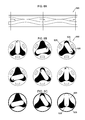
- FIGS. 6A , 6 B and 6 C depict how strain is induced in the magnetostrictive material embedded in the housing of an example lobe motor 500 , in accordance with certain embodiments of the present disclosure. Due to the contact forces, the magnetostrictive material may undergo strain as shown for an exemplary 2:3 lobe motor.
- FIG. 6A depicts a partial side cross-sectional view of an exemplary positive displacement motor 500 .
- FIGS. 6B and 6C depict partial cross-sectional views of the exemplary positive displacement motor 500 with non-limiting examples of the magnetostrictive material 525 embedded in the elastomer in the housing 505 and showing the shaft 520 at varying positions during its rotation cycle.
- FIG. 6A depicts a partial side cross-sectional view of an exemplary positive displacement motor 500 .
- FIGS. 6B and 6C depict partial cross-sectional views of the exemplary positive displacement motor 500 with non-limiting examples of the magnetostrictive material 525 embedded in the elastomer in the housing 505 and
- the magnetostrictive material 525 is embedded at positions corresponding to portions of the housing 505 between the two of the plurality of lobes.
- the magnetostrictive material 525 is embedded to encircle a portion of the shaft 520 .
- the number of magnetostrictive material units embedded in the motor may be a function of the number of lobes in the power section of the motor.
- the number of magnetostrictive crystals that can be placed is given by:
- N peizo n ⁇ N c (7)
- N peizo number of magnetostrictive crystals
- N c number of stages in the motor.
- FIG. 7 depicts an example magnetostrictive voltage output diagram 700 , in accordance with certain embodiments of the present disclosure.
- the charge sensitivity or the magnetostrictive constant d defined as the charge generated per unit force applied is given by:
- the voltage sensitivity is defined as the field produced per unit stress applied and is given by the following equation:
- multiple assemblies may be placed in parallel in the stator which can generate enough power to drive downhole tools continuously.
- the differential pressure across the motor may be dependent on the weight on bit (WOB). The relationship between the pressure drop across the motor in terms of the WOB given below may be used to further calculate the contact force across the seal line.
- K b formation hardness, teeth, bearing, mud coefficient
- certain embodiments of the present disclosure allow for harvesting mechanical energy downhole and generating electrical power therefrom.
- the figures may depict embodiments of the present disclosure in a particular orientation, it should be understood by those skilled in the art that embodiments of the present disclosure are well suited for use in a variety of orientations. Accordingly, it should be understood by those skilled in the art that the use of directional terms such as above, below, upper, lower, upward, downward and the like are used in relation to the illustrative embodiments as they are depicted in the figures, the upward direction being toward the top of the corresponding figure and the downward direction being toward the bottom of the corresponding figure.
Landscapes
- Engineering & Computer Science (AREA)
- Mechanical Engineering (AREA)
- General Engineering & Computer Science (AREA)
- Life Sciences & Earth Sciences (AREA)
- Combustion & Propulsion (AREA)
- Chemical & Material Sciences (AREA)
- Geology (AREA)
- Mining & Mineral Resources (AREA)
- Physics & Mathematics (AREA)
- Environmental & Geological Engineering (AREA)
- Fluid Mechanics (AREA)
- General Life Sciences & Earth Sciences (AREA)
- Geochemistry & Mineralogy (AREA)
- Connection Of Motors, Electrical Generators, Mechanical Devices, And The Like (AREA)
Abstract
Description
- This application claims the benefit of U.S. Provisional Application No. 61/451,351, which was filed Mar. 10, 2011 and is hereby incorporated by reference in its entirety.
- The present disclosure relates generally to wellbore operations and, more particularly, to systems and methods of harvesting energy in a wellbore with a positive displacement motor.
- The recent increase in deepwater and ultra-deep wells has triggered a need for reliable downhole tools which can stay downhole for long hours. It is well known that downhole tools are run with measurement, while drilling tools and other instrumented bottomhole assembly steer the system in the proper direction. All these tools need power which is either stored in batteries or conveyed to the tool through umbilical cords. Supply of a suitable amount of power to these tools is necessary to ensure the tools work effectively and stay downhole for long hours along with other tools. As is well known, batteries have the capability of storing only a finite amount of power therein and have environmental limits, such as temperature, on their use. Frequent battery power pack replacement or failure of the tools during the operation incrementally increases the operating cost despite deriving potential benefits from using these tools. What is needed for such a system in order to manage power is a tool to generate power downhole. The required tool or system should be able to produce power by reclaiming the energy lost downhole instead of using the hydraulic energy conveyed downhole.
- Some specific exemplary embodiments of the disclosure may be understood by referring, in part, to the following description and the accompanying drawings.
-
FIG. 1A depicts a partial cross-sectional view of an exemplary positive displacement motor, in accordance with certain embodiments of the present disclosure. -
FIG. 1B depicts a partial side view of the positive displacement motor an exemplary positive displacement motor, in accordance with certain embodiments of the present disclosure. -
FIG. 2 depicts the electrical and mechanical components in the power section of an exemplary positive displacement motor used in an exemplary coupled electromechanical system, in accordance with certain embodiments of the present disclosure. -
FIG. 3A depicts a partial cross-sectional view of one non-limiting example of the magnetostrictive material embedded in the elastomeric housing of an example positive displacement motor, in accordance with certain embodiments of the present disclosure. -
FIG. 3B depicts a partial cross-sectional view of another non-limiting example of the magnetostrictive material embedded in the elastomeric housing of an example positive displacement motor, in accordance with certain embodiments of the present disclosure -
FIG. 4 depicts an example schematic circuit between the mechanical and electrical components of an exemplary coupled electromechanical system, in accordance with certain embodiments of the present disclosure. -
FIG. 5 depicts components of force acting on the housing of an example three-lobe motor, in accordance with certain embodiments of the present disclosure. -
FIGS. 6A , 6B and 6C depict how strain is induced in the magnetostrictive material embedded in the housing of an example lobe motor, in accordance with certain embodiments of the present disclosure. -
FIG. 7 depicts an example magnetostrictive voltage output diagram, in accordance with certain embodiments of the present disclosure. - While embodiments of this disclosure have been depicted and described and are defined by reference to exemplary embodiments of the disclosure, such references do not imply a limitation on the disclosure, and no such limitation is to be inferred. The subject matter disclosed is capable of considerable modification, alteration, and equivalents in form and function, as will occur to those skilled in the pertinent art and having the benefit of this disclosure. The depicted and described embodiments of this disclosure are examples only, and not exhaustive of the scope of the disclosure.
- The present disclosure relates generally to wellbore operations and, more particularly, to systems and methods of harvesting energy in a wellbore with a positive displacement motor.
- Illustrative embodiments of the present disclosure are described in detail herein. In the interest of clarity, not all features of an actual implementation may be described in this specification. It will of course be appreciated that in the development of any such actual embodiment, numerous implementation specific decisions must be made to achieve the specific implementation goals, which will vary from one implementation to another. Moreover, it will be appreciated that such a development effort might be complex and time consuming, but would nevertheless be a routine undertaking for those of ordinary skill in the art having the benefit of the present disclosure.
- To facilitate a better understanding of the present disclosure, the following examples of certain embodiments are given. In no way should the following examples be read to limit, or define, the scope of the disclosure. Embodiments of the present disclosure may be applicable to horizontal, vertical, deviated, or otherwise nonlinear wellbores in any type of subterranean formation. Embodiments may be applicable to injection wells as well as production wells, including hydrocarbon wells. Devices and methods in accordance with certain embodiments may be used in one or more of wireline, measurement-while-drilling (MWD) and logging-while-drilling (LWD) operations.
- This disclosure generally relates to converting energy to a valuable form of useful power that is otherwise wasted with the use of an existing and extensively used downhole tool called a positive displacement motor. Development of hydraulic downhole motors has a long history. The Archimedean screw pump of ancient times consisted of a spiral shaft which, when turned by hand, lifted water from a lake. Rene Moineau, a French engineer was the first to invent and obtain several modified patents for a rotary type pump between 1930 and 1948 and further developed the Archimedean screw pump principle. The basic parts of a Moineau-type motor involves a stator (housing) and a shaft enclosed in a casing. The shaft has a wave-shaped vertical cross-section, and each wave corresponds to a lobe. The housing, which may be contained in a casing, accommodates the wave-shaped rotor having a cross-section that is also wave-shaped, but the number of lobes is one more than in the shaft. Moineau's pump principle is applied in reverse to rotate the shaft by pumping fluid. This results in a positive displacement motor, commonly known as a PDM.
- There are different designs for positive displacement motors, but the basic operating principle is common to all. The various designs of the PDMs are identified by the ratio of the number of lobes on the shaft to the number of lobes on the housing. Motors with the lobe patterns, such as 1:2, 3:4, 5:6, and 9:10, are now being used. The ratio is known as kinematic ratio, i, of the motor.
-
FIG. 1A depicts a partial cross-sectional view of an exemplarypositive displacement motor 100, in accordance with certain embodiments of the present disclosure.FIG. 1B depicts a partial side view of thepositive displacement motor 100. As depicted, thepositive displacement motor 100 may include ahousing 105. Thehousing 105 may include a suitable elastomeric material. Anouter casing 110 of any suitable material may surround all or a portion of thehousing 105. Thehousing 105 may form acavity 115 havinglobes shaft 120 may be disposed within thecavity 115 and may be a single-lobed shaft. As depicted, a pitch of theshaft 120 is denoted as ps, and a pitch of thehousing 105 is denoted as ph. Accordingly, thedisplacement motor 100 may be an example of a 1:2 lobe configuration providing an eccentric rotation of theshaft 120 in operation. - The eccentric rotation of the
shaft 120 may be a source of vibration. With conventional motors having such eccentricity, the life of the motor may be reduced due to undesirable resonant vibration. With certain embodiments according to the present disclosure, the embodiments not only serve as a source of power generation, but also act as a vibration damping mechanism by way of suppressing the resonant mechanical response. - In certain embodiments according to the present disclosure, magnetostrictive technology may be capable of generating electrical power by using the mechanical energy generated from a downhole motor, e.g., during the process of drilling a borehole. Magnetostrictive materials have the ability to convert kinetic energy into magnetic energy that may be used to generate electrical power. Magnetostrictive materials have the property that, when strain is induced in the material, the change in linear dimensions produces a corresponding change in magnetic field about the material. In other words, mechanical loads can deform the material and thereby rotate magnetic domains. The change of the magnetic flux can be used to generate electrical power. A suitable material for the magnetostrictive material may be Terfenol-D, available from Etrema Products, Inc. Various materials, e.g., iron and iron alloys such as Terfenol, may provide suitable magnetostrictive and giant magnetostrictive responses. These materials normally respond to a force applied to their mechanical connection by creating a magnetic field which can be detected, for example, by a surrounding conductor coil.
- The exemplary
positive displacement motor 100 may be based, at least in part, on the theory of energy-reclamation from the conversion of strain energy induced by the rotation of the shaft to useful electrical energy using magnetostrictive material. The focus may be on the eccentric motion of theshaft 120 inside theelastomeric housing 105. The eccentric motion of theshaft 120 may compress theelastomeric housing 105. The magnetostrictive material embedded in the elastomer may use the strain energy to generate an electrical charge distribution producing a magnetic field which may be converted to electrical energy. In alternative embodiments, instead of or in combination with elastomeric material, thehousing 105 may comprise any other suitable material that would allow transfer of the forces of the rotating shaft to strain the magnetostrictive material embedded in thehousing 105. -
FIG. 2 depicts the electrical and mechanical components in the power section of an exemplarypositive displacement motor 100 used in an exemplary coupled electromechanical system, in accordance with certain embodiments of the present disclosure. Though themagnetostrictive material 125 embedded in thehousing 105 is depicted with exemplary non-limiting form, extent, location, and orientation, themagnetostrictive material 125 may take any suitable form, extent, location, and orientation. One or more portions of themagnetostrictive material 125 may be disposed alongside theshaft 120 in any suitable form, extent, location, and orientation to capture the compression transferred from theshaft 120 to thehousing 105. In this way, rotation of theshaft 120 may be converted into mechanical stress and further converted into electrical charge through the use of themagnetostrictive material 125 embedded inside thehousing 105. The pressure applied to the polarized crystals may produce a mechanical deformation, which in turn generates an electrical charge distribution producing a magnetic field inside and/or about the magnetostrictive material, which in turn may result in an electrical charge captured by one or moreproximate conductors 130. The one or moreproximate conductors 130 may be coupled to any suitable electrical/electronic components. Then, the electrical charge may be rectified and regulated to provide a reliable power supply. In such a manner, the magnetostrictive material may be a transition element between the mechanical and electrical domains. When mud or other fluid passes through themotor 100, theshaft 120 starts rotating. The rotary motion strains the elastomeric housing material. Due to the nature of the magnetostrictive material, the crystals may shift and realign, developing an electrostatic potential between the opposing faces of the element. -
Magnetostrictive materials 125 may also damp the mechanical vibrations caused by the motor rotation. The vibrational mechanical energy may be converted and dissipated into electrical energy throughmagnetostrictive material 125. When the elastomer, and thereby the magnetostrictive material, is compressed due to the rotation of theshaft 120, electrical charge distribution may occur inside themagnetostrictive material 125, producing a magnetic field which in turn causes flow of electric current. Passive shunt networks may be the easiest and cost effective way of suppressing the vibrations. -
FIG. 3A depicts a partial cross-sectional view of one non-limiting example of themagnetostrictive material 125 embedded in theelastomeric housing 105 of an examplepositive displacement motor 100, in accordance with certain embodiments of the present disclosure. As depicted, themagnetostrictive material 125 may have a rectangular form and may be disposed alongside opposing sides of thecavity 115.FIG. 3B depicts a partial cross-sectional view of another non-limiting example of themagnetostrictive material 125 embedded in theelastomeric housing 105 of an examplepositive displacement motor 100. As depicted, themagnetostrictive material 125 may have a form that surrounds a portion of theshaft 120. Again, even though certain non-limiting examples are depicted, it should be understood that themagnetostrictive material 125 may implemented with any suitable form and orientation. -
FIG. 4 depicts an exampleschematic circuit 400 between the mechanical and electrical components of an exemplary coupled electromechanical system, in accordance with certain embodiments of the present disclosure. In the illustrated embodiment, the force F and voltage V across the magnetostrictive material may be the generalized effort variables, whereas the speed N and current I may be the generalized flow variables. In the mechanical domain, Rm may be the mechanical damping; Cm may be the compliance of the housing. In the electrical domain, Cp may be the capacitance; Rc may be dielectric loss. The transfer of energy from the magnetostrictive material to a storage element (not shown) such as a battery may be facilitated in any suitable manner. - With respect to the geometrical description and kinematical understanding of the power section of certain embodiments, contact forces may be needed to estimate the amount of force applied to the magnetostrictive material. The rubbing of the shaft with the housing element may result in the loss of useful power due to friction leakage losses. The main causes are the contact forces and the frictional forces. When the shaft is not rotating, the contacts between the shaft and housing elements may be along the seal lines. Thus, the housing surface may be rubbed over by the shaft surface continuously. As the winding ratio of the motor increases, the number of seal lines also increases. This further adds to the increase in the intensity of the rub.
- The shaft and housing element may cause compressive contact stresses when the shaft rolls. Contact stresses are functions of shaft, housing geometry, material properties of housing element, shaft, surface treatment and the forces acting. Several mathematical models have been proposed by researchers to calculate the contact stresses. Because of the sliding velocity, the elastohydrodynamic effects present in the housing element alters the stress distribution. Another factor which alters the stress at the contact points is dynamic loading. The force Fn, acting on the contact point needs to be evaluated.
-
FIG. 5 depicts components of force acting on thehousing 515 of an example three-lobepositive displacement motor 500, in accordance with certain embodiments of the present disclosure. Thepositive displacement motor 500 may correspond to thepositive displacement motor 100 is many respects except those differences to a three-lobe configuration vis-à-vis a two-lobe configuration. The rotor mass eccentricity may cause a radial force, Fr, on theshaft 520. Also, the fluid pressure may cause a pressure thrust, Fp, on theshaft 520 which may further contribute to the force at the contact points. Theshaft 520 may then transmit this rotating centrifugal force to the contact points of thehousing 515 andshaft 520. Relatively small amounts of mass eccentricity in the shaft may cause unacceptable or even dangerous levels of contact forces at critical speed. - In certain exemplary embodiments, the radial force acting is given by:
-
F r=4π2 A s L(s)eρ ms N 2 (1) - where
- e=eccentricity,
- As =area of the cross section of the shaft,
- ρms=mass density of the shaft, and
- N=rotational speed per minute, rpm.
- In certain exemplary embodiments, this radial force may be carried by the contacts throughout when the shaft rotates. The force due to the fluid pressure is given by:
-
F p =Δp×A r (2) - where
- Δp=pressure difference between the cavities,
- Ar=surface area in which pressure is acting=2πrsL(S), and
- L(S)=length of the seal line.
- In certain exemplary embodiments, the pressure force for a multilobe motor is:
-
F P =Δp(2πr s)iL(S) (3) - The resultant force acting at the contact point is given by:
-
- where
- l=winding or configuration
-
- and
- n=number of shaft lobes of the motor (winding number).
- In order to quantify the degree of contact force between the shaft and housing, a term called “contact force intensity” is defined. Contact force intensity, CFI, is defined as the product of force at the contact point of shaft and housing element and the linear extent of the seal line, which is being rubbed. This is expressed mathematically:
-
- where
- r=radius of the element, and
- ds=the incremental distance along the seal line.
- In certain exemplary embodiments, the rubbing intensity for a multilobe motor of (n+1) seal lines is given by:
-
-
FIGS. 6A , 6B and 6C depict how strain is induced in the magnetostrictive material embedded in the housing of anexample lobe motor 500, in accordance with certain embodiments of the present disclosure. Due to the contact forces, the magnetostrictive material may undergo strain as shown for an exemplary 2:3 lobe motor.FIG. 6A depicts a partial side cross-sectional view of an exemplarypositive displacement motor 500.FIGS. 6B and 6C depict partial cross-sectional views of the exemplarypositive displacement motor 500 with non-limiting examples of themagnetostrictive material 525 embedded in the elastomer in thehousing 505 and showing theshaft 520 at varying positions during its rotation cycle. InFIG. 6B , themagnetostrictive material 525 is embedded at positions corresponding to portions of thehousing 505 between the two of the plurality of lobes. InFIG. 6C , themagnetostrictive material 525 is embedded to encircle a portion of theshaft 520. - In certain exemplary embodiments, the number of magnetostrictive material units embedded in the motor may be a function of the number of lobes in the power section of the motor.
- In general, the number of magnetostrictive crystals that can be placed is given by:
-
N peizo =n×N c (7) - where
- Npeizo=number of magnetostrictive crystals, and
- Nc=number of stages in the motor.
- In certain exemplary embodiments, an applied force may produce a voltage V=Qf/C, where Qf is the charge resulting from the force and C is the capacitance of the device.
FIG. 7 depicts an example magnetostrictive voltage output diagram 700, in accordance with certain embodiments of the present disclosure. In certain exemplary embodiments, the charge sensitivity or the magnetostrictive constant d defined as the charge generated per unit force applied is given by: -
- where
- Q=charge developed.
- In certain exemplary embodiments, the voltage sensitivity is defined as the field produced per unit stress applied and is given by the following equation:
-
- where
- t=thickness of the transducer,
- l=length,
- w=width,
- ∈=dielectric constant,
- C=capacitance formed in the transducer, and
- Q=charge developed.
- In certain exemplary embodiments, multiple assemblies may be placed in parallel in the stator which can generate enough power to drive downhole tools continuously. In certain exemplary embodiments, the differential pressure across the motor may be dependent on the weight on bit (WOB). The relationship between the pressure drop across the motor in terms of the WOB given below may be used to further calculate the contact force across the seal line.
-
- db=diameter of the bit, in,
- Dh=diameter of the housing, in.,
- ph=pitch of the housing, in.,
- i=winding ratio/configuration,
- Kb=formation hardness, teeth, bearing, mud coefficient,
- Ki=winding ratio coefficient,
- Krc=pressure drop coefficient
- Kx=constant, (5252)
- Ky=constant, (0.01)
- Q=flow rate, cu.in.,
- η=overall efficiency.
- Accordingly, certain embodiments of the present disclosure allow for harvesting mechanical energy downhole and generating electrical power therefrom. And even though the figures may depict embodiments of the present disclosure in a particular orientation, it should be understood by those skilled in the art that embodiments of the present disclosure are well suited for use in a variety of orientations. Accordingly, it should be understood by those skilled in the art that the use of directional terms such as above, below, upper, lower, upward, downward and the like are used in relation to the illustrative embodiments as they are depicted in the figures, the upward direction being toward the top of the corresponding figure and the downward direction being toward the bottom of the corresponding figure.
- Therefore, the present disclosure is well adapted to attain the ends and advantages mentioned as well as those that are inherent therein. The particular embodiments disclosed above are illustrative only, as the present disclosure may be modified and practiced in different but equivalent manners apparent to those skilled in the art having the benefit of the teachings herein. Furthermore, no limitations are intended to the details of construction or design herein shown, other than as described in the claims below. It is therefore evident that the particular illustrative embodiments disclosed above may be altered or modified and all such variations are considered within the scope and spirit of the present disclosure. Also, the terms in the claims have their plain, ordinary meaning unless otherwise explicitly and clearly defined by the patentee. The indefinite articles “a” or “an,” as used in the claims, are defined herein to mean one or more than one of the element that the indefinite article introduces.
Claims (20)
Priority Applications (1)
| Application Number | Priority Date | Filing Date | Title |
|---|---|---|---|
| US13/242,798 US8836179B2 (en) | 2011-03-10 | 2011-09-23 | Systems and methods of energy harvesting with positive displacement motor |
Applications Claiming Priority (2)
| Application Number | Priority Date | Filing Date | Title |
|---|---|---|---|
| US201161451351P | 2011-03-10 | 2011-03-10 | |
| US13/242,798 US8836179B2 (en) | 2011-03-10 | 2011-09-23 | Systems and methods of energy harvesting with positive displacement motor |
Publications (2)
| Publication Number | Publication Date |
|---|---|
| US20120228877A1 true US20120228877A1 (en) | 2012-09-13 |
| US8836179B2 US8836179B2 (en) | 2014-09-16 |
Family
ID=46794847
Family Applications (1)
| Application Number | Title | Priority Date | Filing Date |
|---|---|---|---|
| US13/242,798 Active 2033-02-26 US8836179B2 (en) | 2011-03-10 | 2011-09-23 | Systems and methods of energy harvesting with positive displacement motor |
Country Status (1)
| Country | Link |
|---|---|
| US (1) | US8836179B2 (en) |
Cited By (5)
| Publication number | Priority date | Publication date | Assignee | Title |
|---|---|---|---|---|
| US20130099500A1 (en) * | 2011-10-20 | 2013-04-25 | Scientific Drilling International, Inc. | Downhole Apparatus for Electrical Power Generation From Shaft Flexure |
| US20140009007A1 (en) * | 2012-07-05 | 2014-01-09 | Oscilla Power Inc. | Axial loading for magnetostrictive power generation |
| US20140167422A1 (en) * | 2012-12-18 | 2014-06-19 | Oscilla Power Inc. | Downhole energy harvesting method and device |
| US20220403811A1 (en) * | 2019-08-19 | 2022-12-22 | Alliance For Sustainable Energy, Llc | Flexible wave energy converter |
| US11646114B2 (en) | 2016-08-26 | 2023-05-09 | Sap Se | Method and system for processing of electronic medical invoices |
Citations (9)
| Publication number | Priority date | Publication date | Assignee | Title |
|---|---|---|---|---|
| US2328496A (en) * | 1939-03-22 | 1943-08-31 | Rocard Yves | Magnetostrictive microphone |
| US3294994A (en) * | 1963-05-10 | 1966-12-27 | Bendix Corp | Nutation motor or generator |
| US3350583A (en) * | 1963-11-13 | 1967-10-31 | Edward L Schiavone | Electric power supply |
| US4864548A (en) * | 1986-06-13 | 1989-09-05 | Image Acoustics, Inc. | Flextensional transducer |
| US5747915A (en) * | 1996-08-19 | 1998-05-05 | Sandia Corporation | Bent shaft motor |
| JP2002013989A (en) * | 2000-06-28 | 2002-01-18 | Toyota Industries Corp | Torque sensor and its manufacturing method |
| US20100127582A1 (en) * | 2009-07-22 | 2010-05-27 | Hifunda, Llc | Method and device for energy generation |
| US20120228875A1 (en) * | 2011-03-10 | 2012-09-13 | Hardin Jr John R | Systems and methods of harvesting energy in a wellbore |
| US20130099500A1 (en) * | 2011-10-20 | 2013-04-25 | Scientific Drilling International, Inc. | Downhole Apparatus for Electrical Power Generation From Shaft Flexure |
Family Cites Families (3)
| Publication number | Priority date | Publication date | Assignee | Title |
|---|---|---|---|---|
| US7816797B2 (en) | 2009-01-07 | 2010-10-19 | Oscilla Power Inc. | Method and device for harvesting energy from ocean waves |
| US7816833B2 (en) | 2009-11-20 | 2010-10-19 | Oscilla Power Inc. | Method and device for energy generation |
| US8097990B2 (en) | 2010-02-18 | 2012-01-17 | Oscilla Power Inc. | Electrical generator that utilizes rotational to linear motion conversion |
-
2011
- 2011-09-23 US US13/242,798 patent/US8836179B2/en active Active
Patent Citations (9)
| Publication number | Priority date | Publication date | Assignee | Title |
|---|---|---|---|---|
| US2328496A (en) * | 1939-03-22 | 1943-08-31 | Rocard Yves | Magnetostrictive microphone |
| US3294994A (en) * | 1963-05-10 | 1966-12-27 | Bendix Corp | Nutation motor or generator |
| US3350583A (en) * | 1963-11-13 | 1967-10-31 | Edward L Schiavone | Electric power supply |
| US4864548A (en) * | 1986-06-13 | 1989-09-05 | Image Acoustics, Inc. | Flextensional transducer |
| US5747915A (en) * | 1996-08-19 | 1998-05-05 | Sandia Corporation | Bent shaft motor |
| JP2002013989A (en) * | 2000-06-28 | 2002-01-18 | Toyota Industries Corp | Torque sensor and its manufacturing method |
| US20100127582A1 (en) * | 2009-07-22 | 2010-05-27 | Hifunda, Llc | Method and device for energy generation |
| US20120228875A1 (en) * | 2011-03-10 | 2012-09-13 | Hardin Jr John R | Systems and methods of harvesting energy in a wellbore |
| US20130099500A1 (en) * | 2011-10-20 | 2013-04-25 | Scientific Drilling International, Inc. | Downhole Apparatus for Electrical Power Generation From Shaft Flexure |
Cited By (9)
| Publication number | Priority date | Publication date | Assignee | Title |
|---|---|---|---|---|
| US20130099500A1 (en) * | 2011-10-20 | 2013-04-25 | Scientific Drilling International, Inc. | Downhole Apparatus for Electrical Power Generation From Shaft Flexure |
| US9093875B2 (en) * | 2011-10-20 | 2015-07-28 | Scientific Drilling International, Inc. | Downhole apparatus for electrical power generation from shaft flexure |
| US20140009007A1 (en) * | 2012-07-05 | 2014-01-09 | Oscilla Power Inc. | Axial loading for magnetostrictive power generation |
| US9634233B2 (en) * | 2012-07-05 | 2017-04-25 | Oscilla Power, Inc. | Axial loading for magnetostrictive power generation |
| US20140167422A1 (en) * | 2012-12-18 | 2014-06-19 | Oscilla Power Inc. | Downhole energy harvesting method and device |
| US9634234B2 (en) * | 2012-12-18 | 2017-04-25 | Oscilla Power, Inc. | Downhole energy harvesting method and device |
| US11646114B2 (en) | 2016-08-26 | 2023-05-09 | Sap Se | Method and system for processing of electronic medical invoices |
| US20220403811A1 (en) * | 2019-08-19 | 2022-12-22 | Alliance For Sustainable Energy, Llc | Flexible wave energy converter |
| US11815060B2 (en) * | 2019-08-19 | 2023-11-14 | Alliance For Sustainable Energy, Llc | Flexible wave energy converter |
Also Published As
| Publication number | Publication date |
|---|---|
| US8836179B2 (en) | 2014-09-16 |
Similar Documents
| Publication | Publication Date | Title |
|---|---|---|
| US10250103B2 (en) | Electricity generation within a downhole drilling motor | |
| US8836179B2 (en) | Systems and methods of energy harvesting with positive displacement motor | |
| US9948213B2 (en) | Magnetostrictive power supply for bottom hole assembly with rotation-resistant housing | |
| US6717283B2 (en) | Annulus pressure operated electric power generator | |
| US10014802B2 (en) | Systems and methods of harvesting energy in a wellbore | |
| US8899351B2 (en) | Apparatus and method for adjusting power units of downhole motors | |
| GB2375778A (en) | Utilization of energy from flowing fluids | |
| US8981586B2 (en) | Systems and methods to harvest fluid energy in a wellbore using preloaded magnetostrictive elements | |
| CN105683481A (en) | Rotor bearing for progressing cavity downhole drilling motor | |
| US10431998B2 (en) | Sub for a pipe assembly and system and method for use of same | |
| US10017996B2 (en) | Magnetostrictive motor for a borehole assembly | |
| Robello Samuel et al. | Optimal design of progressing cavity pumps (PCP) | |
| Zhongxian et al. | Downhole permanent magnet synchronous motor PMSM drive PCP-wide range of speed, output and high efficiency | |
| Samuel | Analysis of energy harvesting positive displacement motor | |
| Andersson et al. | A Flexible Chain Proposal for Winch-Based Point Absorbers | |
| Lea et al. | New and expected developments in artificial lift | |
| Tao et al. | Downhole Power Generation: Status, Problems, and Prospects | |
| US20240084674A1 (en) | Devices, systems, and methods for downhole power generation | |
| Hazenberg et al. | Latest technology equidistant power section increases overall performance of a workover motor | |
| Nguyen | Progressing Cavity Pump | |
| CN119496268A (en) | Near-bit multi-source power supply device | |
| WO2019245673A1 (en) | Drilling component coupler for reinforcement |
Legal Events
| Date | Code | Title | Description |
|---|---|---|---|
| AS | Assignment |
Owner name: HALLIBURTON ENERGY SERVICES, INC., TEXAS Free format text: ASSIGNMENT OF ASSIGNORS INTEREST;ASSIGNOR:SAMUEL, ROBELLO;REEL/FRAME:026960/0149 Effective date: 20110922 |
|
| STCF | Information on status: patent grant |
Free format text: PATENTED CASE |
|
| MAFP | Maintenance fee payment |
Free format text: PAYMENT OF MAINTENANCE FEE, 4TH YEAR, LARGE ENTITY (ORIGINAL EVENT CODE: M1551) Year of fee payment: 4 |
|
| MAFP | Maintenance fee payment |
Free format text: PAYMENT OF MAINTENANCE FEE, 8TH YEAR, LARGE ENTITY (ORIGINAL EVENT CODE: M1552); ENTITY STATUS OF PATENT OWNER: LARGE ENTITY Year of fee payment: 8 |