US20120186355A1 - Air pump pressure gauge - Google Patents
Air pump pressure gauge Download PDFInfo
- Publication number
- US20120186355A1 US20120186355A1 US13/011,689 US201113011689A US2012186355A1 US 20120186355 A1 US20120186355 A1 US 20120186355A1 US 201113011689 A US201113011689 A US 201113011689A US 2012186355 A1 US2012186355 A1 US 2012186355A1
- Authority
- US
- United States
- Prior art keywords
- casing
- inner tube
- air
- movable member
- air pump
- Prior art date
- Legal status (The legal status is an assumption and is not a legal conclusion. Google has not performed a legal analysis and makes no representation as to the accuracy of the status listed.)
- Granted
Links
- 230000004308 accommodation Effects 0.000 claims abstract description 25
- 238000004891 communication Methods 0.000 claims abstract description 11
- 238000005086 pumping Methods 0.000 claims description 11
- 238000009825 accumulation Methods 0.000 description 5
- 230000008878 coupling Effects 0.000 description 3
- 238000010168 coupling process Methods 0.000 description 3
- 238000005859 coupling reaction Methods 0.000 description 3
- 238000009434 installation Methods 0.000 description 3
- 230000002452 interceptive effect Effects 0.000 description 3
- 238000006073 displacement reaction Methods 0.000 description 2
- 230000000694 effects Effects 0.000 description 2
- 238000005259 measurement Methods 0.000 description 2
- 238000007789 sealing Methods 0.000 description 2
- NIXOWILDQLNWCW-UHFFFAOYSA-N acrylic acid group Chemical group C(C=C)(=O)O NIXOWILDQLNWCW-UHFFFAOYSA-N 0.000 description 1
- 238000009530 blood pressure measurement Methods 0.000 description 1
- 239000011521 glass Substances 0.000 description 1
- 238000012986 modification Methods 0.000 description 1
- 230000004048 modification Effects 0.000 description 1
- 230000035945 sensitivity Effects 0.000 description 1
Images


Classifications
-
- F—MECHANICAL ENGINEERING; LIGHTING; HEATING; WEAPONS; BLASTING
- F04—POSITIVE - DISPLACEMENT MACHINES FOR LIQUIDS; PUMPS FOR LIQUIDS OR ELASTIC FLUIDS
- F04B—POSITIVE-DISPLACEMENT MACHINES FOR LIQUIDS; PUMPS
- F04B33/00—Pumps actuated by muscle power, e.g. for inflating
- F04B33/005—Pumps actuated by muscle power, e.g. for inflating specially adapted for inflating tyres of non-motorised vehicles, e.g. cycles, tricycles
Definitions
- the present invention relates to a pressure measurement apparatus and more specifically, to an air pump pressure gauge.
- U.S. Pat. No. 3,981,625 discloses an air pump in which a transparent handle and a piston are configured to form a pressure gauge.
- U.S. Pat. No. 5,779,457 discloses a view window type pressure gauge.
- US6196807B1 also discloses a view window type pressure gauge.
- US2002/0174723A1 discloses an electronic pressure gauge.
- the analog pressure gauge is attached to the outside of the housing of the air pump that may interfere with the user's operation in pumping the air pump.
- a small tubular passage protrudes over the outside wall of the air pump casing for accommodating the pressure gauge. Due to the limitation of the outer diameter of the air pump, the view window is small, not facilitating viewing of the readings.
- the present invention has been accomplished under the circumstances in view. It is the main object of the present invention to provide an air pump pressure gauge, which is kept inside the body of the air pump to indicate the pressure value clearly without interfering with the pumping operation, allowing the user to view and read the readings conveniently.
- an air pump pressure gauge used in an air pump, comprises a casing shaped like a tube; an inner tube coaxially and fixedly mounted ins aid casing and defining with the casing an annular accommodation space, the inner tube having one end thereof connected to an air nozzle assembly of the air pump and an opposite end thereof kept in air communication with an air-pumping passage of the air pump; a movable member being an annular member sleeved onto the inner tube within the casing and movable back and forth in the annular accommodation space; a spring member installed in the annular accommodation space and stopped between one end of the annular accommodation space and the movable member to provide a return force to the movable member toward an opposite end wall of the annular accommodation space; at least one seal member mounted on the movable member to define a first airtight structure between the outer surface of the inner tube and the at least one seal member and a second airtight structure between the inside wall of the casing and the at least one seal member; an
- the pressure gauge As the pressure gauge is kept inside the casing, it does not interfere with the pumping operation.
- the pressure indicating structure is large enough to facilitate reading. Further, the pressure indicating structure is large enough to clearly indicate the pressure value, facilitate reading.
- FIG. 1 is a sectional view of an air pump in accordance with a first embodiment of the present invention, illustrating the initial status.
- FIG. 2 is an exploded view of the air pump in accordance with the first embodiment of the present invention.
- FIG. 3 is similar to FIG. 1 , illustrating a pumping status.
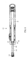
- FIG. 4 is a top view of the pressure gauge shown in FIG. 3 , illustrating a pressure measuring status.
- FIG. 5 is a top view of the pressure gauge shown in FIG. 1 , illustrating the still (start) status.
- FIG. 6 is a sectional view of is an air pump in accordance with a second embodiment of the present invention.
- FIG. 7 is an exploded view of the air pump in accordance with the second embodiment of the present invention.
- FIG. 8 is a sectional view of is an air pump in accordance with a third embodiment of the present invention.
- FIG. 9 is a top view of FIG. 8 .
- FIG. 10 is an exploded view of the air pump in accordance with the third embodiment of the present invention.
- a handheld air pump 10 in accordance with a first embodiment of the invention comprising:
- a pump head 12 holding therein an air nozzle assembly 14 which is a known design and therefore no further description in this regard is necessary, having a coupling portion 18 located on one side thereof;
- a casing 16 shaped like a tube and fixedly connected to the pump head 12 , having a connection end portion 20 located on its one end and mounted with an O-ring 24 and then fastened to the coupling portion 18 of the pump head 12 with two pins 22 and defining therein an axial through hole 26 in communication with an air hole 28 in the coupling portion 18 of the pump head 12 ;
- an inner tube 30 having one end 32 thereof coaxially fastened to the inside of the connection end portion 20 of the casing 16 , two protrusions 52 raised from the periphery thereof at two opposite sides and an opposite end thereof extending out of the casing 16 to work as an axle (air-pumping passage) of the handheld air pump 10 such that the axial hole 36 of the inner tube 30 is in communication with the air hole 28 via the axial through hole 26 and an annular accommodation space 38 is defined within the casing 16 around the inner tube 30 ;
- an end cap 40 being an annular member sleeved onto the inner tube 30 within the casing 16 to seal one end of the annular accommodation space 38 ;
- a movable member 42 being an annular member sleeved onto the inner tube 30 within the casing 16 to divide the annular accommodation space 38 into a first accumulation chamber 381 and a second accumulation chamber 382 , having at least one, for example, two longitudinal sliding slots 44 spaced from each other at 180°, a rack 46 extending along one side of one longitudinal sliding slot 44 , two notches 50 respectively located on the inside wall 48 of the movable member 42 at one end of each of the two longitudinal sliding slots 44 for the passing of the protrusions 52 of the inner tube 30 so that the matching arrangement of the protrusions 52 and the longitudinal sliding slots 44 provide a function to prohibit rotation of the movable member 42 (it is to be understood that one single longitudinal sliding slot 44 with one single protrusion 52 can achieve the same effect, however this design has a directional installation limitation; the design of two longitudinal sliding slot with two protrusions has no direction limitation in installation);
- a spring member 54 installed in the second accumulation chamber 382 and stopped with its one end against the end cap 40 and its other end stopped against the movable member 42 to provide a return force after movement of the movable member 42 toward the end 32 of the inner tube 30 ;
- a first seal member 56 being an O-ring mounted on the other end 58 of the movable member 42 such that a first airtight structure 60 is formed between the outer surface 30 and the first seal member 56 ;
- a second seal member 62 shaped like a horn and fastened to the other end 58 of the movable member 42 such that a second airtight structure 64 is formed between the second seal member 62 and the inside wall of the casing 16 ;
- a locating member 66 located on the other end 58 of the movable member 42 to hold down the first seal member 56 on the movable member 42 ;
- an air hole 68 located on the inner tube 30 and abutted to the inside wall of the connection end portion 20 of the casing 16 between the first airtight structure 60 and the inside wall of the connection end portion 20 for communication between the inner tube 30 and the first accumulation chamber 381 ;
- a rotating axle 70 radially inserted through a through hole 72 on the casing 16 and the annular accommodation space 38 in the casing 16 and the longitudinal sliding slots 44 of the movable member 42 , having its inner end pivotally connected to the protrusions 52 of the inner tube 30 and its outer end extending out of the casing 16 and a gear 74 fixedly mounted on the middle between its inner and outer ends and meshed with the rack 46 of the movable member 42 such that moving the movable member 42 along the axis of the inner tube 30 causes rotation of the rotating axle 70 forwardly or backwardly;
- a pointer 76 fixedly connected to the outer end of the rotating axle 70 and suspending outside the casing 16 ;
- a graduation scale 78 mounted on the outside wall of the casing 16 below the pointer 76 ;
- a transparent cover 80 fastened to the casing 16 and covered over the graduation scale 78 and the pointer 76 .
- the inner tube 30 has a piston 84 affixed to its other end 34 .
- the piston 84 has a center through hole 86 in communication with the axial hole 36 of the inner tube 30 and a one-way valve 88 mounted in the center through hole 86 for allowing air to pass through the center through hole 86 into the axial hole 36 of the inner tube 30 and prohibiting air from flowing in the reversed direction.
- An outer tube 90 is sleeved onto the piston 84 , having an end piece 92 mounted on its one end and facing the casing 16 and an one-way valve 94 mounted on its other end to let outside air enter the outer tube 90 through the one-way valve 94 and to prohibit inside air from flowing out of the outer tube 90 through the one-way valve 94 .
- the piston 84 is also a one-way valve.
- the piston 84 divides the inside space of the outer tube 90 into a first air chamber 96 and a second air chamber 98 , simply allowing air to pass from the first air chamber 96 into the second air chamber 98 .
- the volume of the second air chamber 98 expands for letting in outside air.
- air in the second air chamber 98 is compressed and forced to flow into the inside of the inner tube 30 .
- the pump head 12 when the pump head 12 is attached to the air valve (see the imaginary line) of the object to be inflated (for example, a tire) and the outer tube 90 is reciprocated, the compressed air in the inner tube 30 will flow through the air hole 68 located on the inner tube 30 and abutted to the inside wall of the connection end portion 20 of the casing 16 between the first airtight structure 60 and the inside wall of the connection end portion 20 for communication between the inner tube 30 and the first accumulation chamber 381 to push the movable member 42 toward the end cap 40 to compress the spring member 54 , storing a return spring force.
- the inside pressure of the inflated object rises, the amount of displacement of the movable member 42 is relatively increased. Displacement of the movable member 42 causes the rack 46 to drive the rotating axle 70 to rotate, and therefore the pointer 76 is biased relative to the graduation scale 78 to indicate the pressure value of the inflated object (see FIG. 4 ).
- the one-way valve 88 is mounted in the piston 84 so that no any interference exists between the pump head 12 and the pressure gauge, and the pressure gauge can directly measures the pressure value of the inflated object.
- this one-way valve 88 is normally installed in a through hole 28 in the pump head 12 .
- the protrusions 52 and notches 50 and the longitudinal sliding slots 44 constitute a sliding groove and rail structure to prohibit rotation of the movable member 42 .
- Simply the matching arrangement of the rotating axle 70 and the longitudinal sliding slots 44 can achieve the same effect to prohibit rotation of the movable member 42 .
- FIGS. 6 and 7 illustrate the structure of a second embodiment of the present invention, in which like reference signs denote like component parts.
- the air pump 100 and another air pump pressure gauge eliminates the pump head 12 of the aforesaid first embodiment.
- a flexible tube 102 is set in the inner tube 30 , having an end plug 104 fastened to its inner end.
- the end plug 104 has a center through hole 106 in communication with the axial hole 108 of the flexible tube 102 , and is peripherally mounted with an O-ring 110 that is tightly kept in contact with the inside wall of the inner tube 30 to seal the gap.
- the outer end of the flexible tube 102 is mounted with a valve connector 112 for connection to the air valve of the object to be inflated.
- FIGS. 8-10 illustrate the structure of a third embodiment of the present invention.
- the air pump 200 and still another air pump pressure gauge eliminates is substantially similar to the aforesaid first embodiment with the exception that this third embodiment eliminates the aforesaid rotating axle 70 and pointer 76 and the aforesaid longitudinal sliding slots 44 are eliminated from the movable member 202 .
- an elongated graduation scale 204 is located on the periphery of the movable member 202 .
- the casing 206 has a peephole 208 corresponding to the graduation scale 204 .
- a transparent member 210 (acrylic or glass member) is mounted in the peephole 208 , forming a view window 212 through which one can read the readings of the graduation scale 204 .
- a seal member 214 is attached to the front end of the movable member 202 .
- the seal member 214 has an inner lip 216 that forms with the inner tube 218 a first sealing structure 220 , and an outer lip 222 that forms with the inside wall of the casing 206 a second sealing structure 224 .
- This seal member 214 is a known structure. It can also be used in the aforesaid first or second embodiment.
- the main advantage of the present invention is that the pressure gauge is kept inside the casing without interfering with the pumping operation; the annular movable member receives the pressure of the inflated object, and its sensitivity is directly proportional to its pressure-receiving surface area; the pressure indicating structure is large enough to facilitate reading.
Landscapes
- Engineering & Computer Science (AREA)
- Mechanical Engineering (AREA)
- General Engineering & Computer Science (AREA)
- Measuring Fluid Pressure (AREA)
- Compressors, Vaccum Pumps And Other Relevant Systems (AREA)
Abstract
Description
- 1. Field of the Invention
- The present invention relates to a pressure measurement apparatus and more specifically, to an air pump pressure gauge.
- 2. Description of the Related Art
- Many prior art designs of air pump with pressure gauge are known. Exemplars are seen.
- U.S. Pat. No. 3,981,625 discloses an air pump in which a transparent handle and a piston are configured to form a pressure gauge.
- U.S. Pat. No. 5,779,457 discloses a view window type pressure gauge.
- U.S. Pat. No. 6,132,189 discloses an attached pressure gauge.
- US6196807B1 also discloses a view window type pressure gauge.
- US2002/0174723A1 discloses an electronic pressure gauge.
- US2004/0001761A1 discloses an attached analog pressure gauge.
- US2008/0056922A1 discloses an analog pressure gauge.
- U.S. Pat. No. 4,136,560 discloses a pressure gauge.
- In a conventional air pump with an analog pressure gauge, the analog pressure gauge is attached to the outside of the housing of the air pump that may interfere with the user's operation in pumping the air pump.
- In a conventional air pump with a view window type pressure gauge, a small tubular passage protrudes over the outside wall of the air pump casing for accommodating the pressure gauge. Due to the limitation of the outer diameter of the air pump, the view window is small, not facilitating viewing of the readings.
- In U.S. Pat. No. 4,136,560, the pressure gauge is directly connected to, for example, the air valve of the vehicle tire. Due to this installation limitation, the structural size is limited. In consequence, the pressure indication is not apparent.
- The pressure value indication of U.S. Pat. No. 3,981,625 is large enough for easy reading without interfering with the pumping operation, however, it does not allow measurement of the pressure during pumping. When measuring the air pressure, the user must release the handle and wait for a certain period of time and then view the graduations on the handle. This design is inconvenient to use.
- The present invention has been accomplished under the circumstances in view. It is the main object of the present invention to provide an air pump pressure gauge, which is kept inside the body of the air pump to indicate the pressure value clearly without interfering with the pumping operation, allowing the user to view and read the readings conveniently.
- To achieve this and other objects of the present invention, an air pump pressure gauge, used in an air pump, comprises a casing shaped like a tube; an inner tube coaxially and fixedly mounted ins aid casing and defining with the casing an annular accommodation space, the inner tube having one end thereof connected to an air nozzle assembly of the air pump and an opposite end thereof kept in air communication with an air-pumping passage of the air pump; a movable member being an annular member sleeved onto the inner tube within the casing and movable back and forth in the annular accommodation space; a spring member installed in the annular accommodation space and stopped between one end of the annular accommodation space and the movable member to provide a return force to the movable member toward an opposite end wall of the annular accommodation space; at least one seal member mounted on the movable member to define a first airtight structure between the outer surface of the inner tube and the at least one seal member and a second airtight structure between the inside wall of the casing and the at least one seal member; an air hole located on the inner tube between the first airtight structure and the opposite end wall of the annular accommodation space for allowing air to pass from the inner tube into the annular accommodation space to move the movable member; a longitudinal sliding slot located on the movable member; a rack located on the movable member and extending along one side of the longitudinal sliding slot; a rotating axle radially extending through the casing and the annular accommodation space, the rotating axle having an inner end thereof pivotally connected to the inner tube and an outer end thereof extending out of the casing and a middle part thereof fixedly mounted with a gear being meshed with the rack of the movable member so that moving the movable member along the axis of the inner tube causes rotation of the rotating axle forwardly/backwardly; a pointer fixedly connected to the outer end of the rotating axle and suspending outside the casing; a graduation scale mounted on the outside of the casing below the pointer; and a transparent cover fastened to the casing and covered over the graduation scale and the pointer.
- As the pressure gauge is kept inside the casing, it does not interfere with the pumping operation. The pressure indicating structure is large enough to facilitate reading. Further, the pressure indicating structure is large enough to clearly indicate the pressure value, facilitate reading.
-
FIG. 1 is a sectional view of an air pump in accordance with a first embodiment of the present invention, illustrating the initial status. -
FIG. 2 is an exploded view of the air pump in accordance with the first embodiment of the present invention. -
FIG. 3 is similar toFIG. 1 , illustrating a pumping status. -
FIG. 4 is a top view of the pressure gauge shown inFIG. 3 , illustrating a pressure measuring status. -
FIG. 5 is a top view of the pressure gauge shown inFIG. 1 , illustrating the still (start) status. -
FIG. 6 is a sectional view of is an air pump in accordance with a second embodiment of the present invention. -
FIG. 7 is an exploded view of the air pump in accordance with the second embodiment of the present invention. -
FIG. 8 is a sectional view of is an air pump in accordance with a third embodiment of the present invention. -
FIG. 9 is a top view ofFIG. 8 . -
FIG. 10 is an exploded view of the air pump in accordance with the third embodiment of the present invention. - Three examples of the invention will be described hereinafter for understanding of the spirit and scope of the invention.
- Referring to
FIGS. 1 and 2 , ahandheld air pump 10 in accordance with a first embodiment of the invention is shown comprising: - a
pump head 12 holding therein anair nozzle assembly 14, which is a known design and therefore no further description in this regard is necessary, having acoupling portion 18 located on one side thereof; - a
casing 16 shaped like a tube and fixedly connected to thepump head 12, having aconnection end portion 20 located on its one end and mounted with an O-ring 24 and then fastened to thecoupling portion 18 of thepump head 12 with twopins 22 and defining therein an axial throughhole 26 in communication with anair hole 28 in thecoupling portion 18 of thepump head 12; - an
inner tube 30 having oneend 32 thereof coaxially fastened to the inside of theconnection end portion 20 of thecasing 16, twoprotrusions 52 raised from the periphery thereof at two opposite sides and an opposite end thereof extending out of thecasing 16 to work as an axle (air-pumping passage) of thehandheld air pump 10 such that theaxial hole 36 of theinner tube 30 is in communication with theair hole 28 via the axial throughhole 26 and anannular accommodation space 38 is defined within thecasing 16 around theinner tube 30; - an
end cap 40 being an annular member sleeved onto theinner tube 30 within thecasing 16 to seal one end of theannular accommodation space 38; - a
movable member 42 being an annular member sleeved onto theinner tube 30 within thecasing 16 to divide theannular accommodation space 38 into afirst accumulation chamber 381 and asecond accumulation chamber 382, having at least one, for example, two longitudinalsliding slots 44 spaced from each other at 180°, arack 46 extending along one side of one longitudinalsliding slot 44, twonotches 50 respectively located on theinside wall 48 of themovable member 42 at one end of each of the two longitudinalsliding slots 44 for the passing of theprotrusions 52 of theinner tube 30 so that the matching arrangement of theprotrusions 52 and thelongitudinal sliding slots 44 provide a function to prohibit rotation of the movable member 42 (it is to be understood that one single longitudinalsliding slot 44 with onesingle protrusion 52 can achieve the same effect, however this design has a directional installation limitation; the design of two longitudinal sliding slot with two protrusions has no direction limitation in installation); - a
spring member 54 installed in thesecond accumulation chamber 382 and stopped with its one end against theend cap 40 and its other end stopped against themovable member 42 to provide a return force after movement of themovable member 42 toward theend 32 of theinner tube 30; - a
first seal member 56 being an O-ring mounted on theother end 58 of themovable member 42 such that afirst airtight structure 60 is formed between theouter surface 30 and thefirst seal member 56; - a
second seal member 62 shaped like a horn and fastened to theother end 58 of themovable member 42 such that asecond airtight structure 64 is formed between thesecond seal member 62 and the inside wall of thecasing 16; - a locating
member 66 located on theother end 58 of themovable member 42 to hold down thefirst seal member 56 on themovable member 42; - an
air hole 68 located on theinner tube 30 and abutted to the inside wall of theconnection end portion 20 of thecasing 16 between thefirst airtight structure 60 and the inside wall of theconnection end portion 20 for communication between theinner tube 30 and thefirst accumulation chamber 381; - a rotating
axle 70 radially inserted through a throughhole 72 on thecasing 16 and theannular accommodation space 38 in thecasing 16 and the longitudinalsliding slots 44 of themovable member 42, having its inner end pivotally connected to theprotrusions 52 of theinner tube 30 and its outer end extending out of thecasing 16 and agear 74 fixedly mounted on the middle between its inner and outer ends and meshed with therack 46 of themovable member 42 such that moving themovable member 42 along the axis of theinner tube 30 causes rotation of the rotatingaxle 70 forwardly or backwardly; - a
pointer 76 fixedly connected to the outer end of the rotatingaxle 70 and suspending outside thecasing 16; - a
graduation scale 78 mounted on the outside wall of thecasing 16 below thepointer 76; and - a
transparent cover 80 fastened to thecasing 16 and covered over thegraduation scale 78 and thepointer 76. - The above description explains the structure of an air pump pressure gauge of the
air pump 10. The other structure of theair pump 10 is briefly described hereinafter. - The
inner tube 30 has apiston 84 affixed to itsother end 34. Thepiston 84 has a center throughhole 86 in communication with theaxial hole 36 of theinner tube 30 and a one-way valve 88 mounted in the center throughhole 86 for allowing air to pass through the center throughhole 86 into theaxial hole 36 of theinner tube 30 and prohibiting air from flowing in the reversed direction. Anouter tube 90 is sleeved onto thepiston 84, having anend piece 92 mounted on its one end and facing thecasing 16 and an one-way valve 94 mounted on its other end to let outside air enter theouter tube 90 through the one-way valve 94 and to prohibit inside air from flowing out of theouter tube 90 through the one-way valve 94. According to this embodiment, thepiston 84 is also a one-way valve. Thepiston 84 divides the inside space of theouter tube 90 into afirst air chamber 96 and asecond air chamber 98, simply allowing air to pass from thefirst air chamber 96 into thesecond air chamber 98. When theouter tube 90 is pulled outwards, the volume of thesecond air chamber 98 expands for letting in outside air. When theouter tube 90 is pushed inwards, air in thesecond air chamber 98 is compressed and forced to flow into the inside of theinner tube 30. - As shown in
FIG. 3 , when thepump head 12 is attached to the air valve (see the imaginary line) of the object to be inflated (for example, a tire) and theouter tube 90 is reciprocated, the compressed air in theinner tube 30 will flow through theair hole 68 located on theinner tube 30 and abutted to the inside wall of theconnection end portion 20 of thecasing 16 between the firstairtight structure 60 and the inside wall of theconnection end portion 20 for communication between theinner tube 30 and thefirst accumulation chamber 381 to push themovable member 42 toward theend cap 40 to compress thespring member 54, storing a return spring force. When the inside pressure of the inflated object rises, the amount of displacement of themovable member 42 is relatively increased. Displacement of themovable member 42 causes therack 46 to drive the rotatingaxle 70 to rotate, and therefore thepointer 76 is biased relative to thegraduation scale 78 to indicate the pressure value of the inflated object (seeFIG. 4 ). - After inflation or measurement, remove the
pump head 12 from the air valve of the inflated object to discharge the compressed air out of theinner tube 30, allowing thespring member 54 to return themovable member 42 to its former (start) position (seeFIG. 1 ), and at the same time, therack 46 of themovable member 42 reverses the rotatingaxle 70 to bias thepointer 76 to its former (start) position, i.e., the zero-reading position (seeFIG. 5 ). - According to this embodiment, the one-
way valve 88 is mounted in thepiston 84 so that no any interference exists between thepump head 12 and the pressure gauge, and the pressure gauge can directly measures the pressure value of the inflated object. In a conventional air pump without pressure gauge, this one-way valve 88 is normally installed in a throughhole 28 in thepump head 12. - In this embodiment, the
protrusions 52 andnotches 50 and the longitudinal slidingslots 44 constitute a sliding groove and rail structure to prohibit rotation of themovable member 42. Simply the matching arrangement of therotating axle 70 and the longitudinal slidingslots 44 can achieve the same effect to prohibit rotation of themovable member 42. -
FIGS. 6 and 7 illustrate the structure of a second embodiment of the present invention, in which like reference signs denote like component parts. According to this second embodiment, theair pump 100 and another air pump pressure gauge eliminates thepump head 12 of the aforesaid first embodiment. As illustrated, aflexible tube 102 is set in theinner tube 30, having anend plug 104 fastened to its inner end. Theend plug 104 has a center throughhole 106 in communication with theaxial hole 108 of theflexible tube 102, and is peripherally mounted with an O-ring 110 that is tightly kept in contact with the inside wall of theinner tube 30 to seal the gap. The outer end of theflexible tube 102 is mounted with avalve connector 112 for connection to the air valve of the object to be inflated. When using theair pump 100, pull theflexible tube 102 out of theinner tube 30. When not in use, push theflexible tube 102 back to the inside of theinner tube 30. -
FIGS. 8-10 illustrate the structure of a third embodiment of the present invention. According to this third embodiment, theair pump 200 and still another air pump pressure gauge eliminates is substantially similar to the aforesaid first embodiment with the exception that this third embodiment eliminates the aforesaidrotating axle 70 andpointer 76 and the aforesaid longitudinal slidingslots 44 are eliminated from themovable member 202. According to this third embodiment, anelongated graduation scale 204 is located on the periphery of themovable member 202. Thecasing 206 has apeephole 208 corresponding to thegraduation scale 204. A transparent member 210 (acrylic or glass member) is mounted in thepeephole 208, forming aview window 212 through which one can read the readings of thegraduation scale 204. Further, aseal member 214 is attached to the front end of themovable member 202. Theseal member 214 has aninner lip 216 that forms with the inner tube 218 afirst sealing structure 220, and anouter lip 222 that forms with the inside wall of the casing 206 asecond sealing structure 224. Thisseal member 214 is a known structure. It can also be used in the aforesaid first or second embodiment. - The main advantage of the present invention is that the pressure gauge is kept inside the casing without interfering with the pumping operation; the annular movable member receives the pressure of the inflated object, and its sensitivity is directly proportional to its pressure-receiving surface area; the pressure indicating structure is large enough to facilitate reading.
- Although particular embodiments of the invention have been described in detail for purposes of illustration, various modifications and enhancements may be made without departing from the spirit and scope of the invention. Accordingly, the invention is not to be limited except as by the appended claims.
Claims (6)
Priority Applications (1)
| Application Number | Priority Date | Filing Date | Title |
|---|---|---|---|
| US13/011,689 US8336386B2 (en) | 2011-01-21 | 2011-01-21 | Air pump pressure gauge |
Applications Claiming Priority (1)
| Application Number | Priority Date | Filing Date | Title |
|---|---|---|---|
| US13/011,689 US8336386B2 (en) | 2011-01-21 | 2011-01-21 | Air pump pressure gauge |
Publications (2)
| Publication Number | Publication Date |
|---|---|
| US20120186355A1 true US20120186355A1 (en) | 2012-07-26 |
| US8336386B2 US8336386B2 (en) | 2012-12-25 |
Family
ID=46543128
Family Applications (1)
| Application Number | Title | Priority Date | Filing Date |
|---|---|---|---|
| US13/011,689 Active 2031-07-30 US8336386B2 (en) | 2011-01-21 | 2011-01-21 | Air pump pressure gauge |
Country Status (1)
| Country | Link |
|---|---|
| US (1) | US8336386B2 (en) |
Cited By (6)
| Publication number | Priority date | Publication date | Assignee | Title |
|---|---|---|---|---|
| CN104564589A (en) * | 2013-10-22 | 2015-04-29 | 吴树木 | Floor inflator allowing pressure data to be wirelessly transmitted to mobile electronic device |
| US20150167656A1 (en) * | 2013-12-17 | 2015-06-18 | Beto Engineering & Marketing Co., Ltd. | Air pump having pivotal pressure gauge |
| US20150377230A1 (en) * | 2014-06-27 | 2015-12-31 | Wen-San Chou | Air compressor |
| US20210239227A1 (en) * | 2020-01-31 | 2021-08-05 | Beto Engineering and Marketing Co., Ltd. | Air inflation device having rotatable pressure gauge |
| US20210239228A1 (en) * | 2020-01-31 | 2021-08-05 | Beto Engineering and Marketing Co., Ltd. | Air inflation device having rotatable pressure gauge |
| CN118617717A (en) * | 2024-08-14 | 2024-09-10 | 浙江云中包装有限公司 | A blister forming mold and blister forming method for packaging box |
Families Citing this family (5)
| Publication number | Priority date | Publication date | Assignee | Title |
|---|---|---|---|---|
| TW201437485A (en) * | 2013-03-20 | 2014-10-01 | Beto Engineering & Marketing | Air pump with dual indication of high and low pressures |
| TWI555911B (en) * | 2013-10-18 | 2016-11-01 | Shu-Mu Wu | A portable pump capable of wirelessly transmitting barometric data to a mobile electronic device Which is a combination with a mobile electronic device |
| TWI592574B (en) * | 2015-08-28 | 2017-07-21 | Flexible and flexible inflator nose | |
| US10174748B2 (en) * | 2016-03-07 | 2019-01-08 | Beto Engineering & Marketing Co., Ltd. | Air pump having concealed pressure gauge |
| US12292126B2 (en) * | 2023-06-07 | 2025-05-06 | Scott Wu | Inflator valve connector |
Citations (15)
| Publication number | Priority date | Publication date | Assignee | Title |
|---|---|---|---|---|
| US3677089A (en) * | 1970-03-18 | 1972-07-18 | Martin Ind Inc | Pressure gauge |
| US4246798A (en) * | 1979-12-03 | 1981-01-27 | J. E. Myles, Inc. | Pressure indicator |
| US4246797A (en) * | 1979-12-03 | 1981-01-27 | J. E. Myles, Inc. | Pressure Indicator |
| US4333491A (en) * | 1979-05-18 | 1982-06-08 | Knubley John S | Air dispensing apparatus |
| US4464929A (en) * | 1981-09-21 | 1984-08-14 | William M. Willis, Sr. | Tire cap pressure gauge |
| US4686855A (en) * | 1984-08-28 | 1987-08-18 | Noel Smith | Inflation pressure indicator for vehicle tires |
| US4986128A (en) * | 1989-12-22 | 1991-01-22 | The Devilbiss Company | In-line pressure gauge |
| US4998438A (en) * | 1990-05-22 | 1991-03-12 | Martin Jerry L | Digital air pressure gauge and inflation device |
| US5819779A (en) * | 1995-10-20 | 1998-10-13 | Fuji Univance Corporation | Tire valve cap for measuring air pressure |
| US6164139A (en) * | 1999-11-09 | 2000-12-26 | Krimmer; Patrick P. | Pressure test gauge assembly |
| US6279599B1 (en) * | 1999-12-21 | 2001-08-28 | Chih-Ming Chen | Air hose assembly for a portable tire pump and having the dual functions of air inflation and pressure release |
| US6878204B1 (en) * | 2001-11-14 | 2005-04-12 | Ams Research Corporation | Methods and apparatus for applying a thermal conductive medium |
| US6978670B2 (en) * | 2004-04-05 | 2005-12-27 | William Cousineau | Tire valve-gauge combination |
| US7197919B2 (en) * | 2004-05-11 | 2007-04-03 | Min Wu | User adjustable calibration feature for a tire pressure gauge |
| US7458270B2 (en) * | 2006-06-02 | 2008-12-02 | Glenn Kiefer | Inflation and pressure gauge apparatus |
Family Cites Families (8)
| Publication number | Priority date | Publication date | Assignee | Title |
|---|---|---|---|---|
| US3981625A (en) | 1974-02-22 | 1976-09-21 | Dahltron Corporation | Pump with gauge means |
| US4136560A (en) | 1976-12-27 | 1979-01-30 | Gellos Alexander T | Pressure gauge |
| US5779457A (en) | 1996-03-29 | 1998-07-14 | Chuang; Louis | Hand pump for pumping air of lower pressure and high pressure |
| US6196807B1 (en) | 1998-07-30 | 2001-03-06 | Scott Wu | Pressure gauge of a bicycle tire pump with accurate indication |
| US6132189A (en) | 2000-03-24 | 2000-10-17 | A-Pro Cycles, Inc. | Combined bicycle tire and air suspension pump with removable pressure gauge |
| US20020174723A1 (en) | 2001-05-23 | 2002-11-28 | Louis Chuang | Detachable pressure gauge for a hand pump |
| US6805537B2 (en) | 2002-07-01 | 2004-10-19 | Scott Wu | Pump with detachable pressure gauge |
| US7661934B2 (en) | 2006-08-30 | 2010-02-16 | Ying-Che Huang | Universal air pump |
-
2011
- 2011-01-21 US US13/011,689 patent/US8336386B2/en active Active
Patent Citations (15)
| Publication number | Priority date | Publication date | Assignee | Title |
|---|---|---|---|---|
| US3677089A (en) * | 1970-03-18 | 1972-07-18 | Martin Ind Inc | Pressure gauge |
| US4333491A (en) * | 1979-05-18 | 1982-06-08 | Knubley John S | Air dispensing apparatus |
| US4246798A (en) * | 1979-12-03 | 1981-01-27 | J. E. Myles, Inc. | Pressure indicator |
| US4246797A (en) * | 1979-12-03 | 1981-01-27 | J. E. Myles, Inc. | Pressure Indicator |
| US4464929A (en) * | 1981-09-21 | 1984-08-14 | William M. Willis, Sr. | Tire cap pressure gauge |
| US4686855A (en) * | 1984-08-28 | 1987-08-18 | Noel Smith | Inflation pressure indicator for vehicle tires |
| US4986128A (en) * | 1989-12-22 | 1991-01-22 | The Devilbiss Company | In-line pressure gauge |
| US4998438A (en) * | 1990-05-22 | 1991-03-12 | Martin Jerry L | Digital air pressure gauge and inflation device |
| US5819779A (en) * | 1995-10-20 | 1998-10-13 | Fuji Univance Corporation | Tire valve cap for measuring air pressure |
| US6164139A (en) * | 1999-11-09 | 2000-12-26 | Krimmer; Patrick P. | Pressure test gauge assembly |
| US6279599B1 (en) * | 1999-12-21 | 2001-08-28 | Chih-Ming Chen | Air hose assembly for a portable tire pump and having the dual functions of air inflation and pressure release |
| US6878204B1 (en) * | 2001-11-14 | 2005-04-12 | Ams Research Corporation | Methods and apparatus for applying a thermal conductive medium |
| US6978670B2 (en) * | 2004-04-05 | 2005-12-27 | William Cousineau | Tire valve-gauge combination |
| US7197919B2 (en) * | 2004-05-11 | 2007-04-03 | Min Wu | User adjustable calibration feature for a tire pressure gauge |
| US7458270B2 (en) * | 2006-06-02 | 2008-12-02 | Glenn Kiefer | Inflation and pressure gauge apparatus |
Cited By (9)
| Publication number | Priority date | Publication date | Assignee | Title |
|---|---|---|---|---|
| CN104564589A (en) * | 2013-10-22 | 2015-04-29 | 吴树木 | Floor inflator allowing pressure data to be wirelessly transmitted to mobile electronic device |
| US20150167656A1 (en) * | 2013-12-17 | 2015-06-18 | Beto Engineering & Marketing Co., Ltd. | Air pump having pivotal pressure gauge |
| US20150377230A1 (en) * | 2014-06-27 | 2015-12-31 | Wen-San Chou | Air compressor |
| US10077770B2 (en) * | 2014-06-27 | 2018-09-18 | Wen-San Chou | Air compressor |
| US20210239227A1 (en) * | 2020-01-31 | 2021-08-05 | Beto Engineering and Marketing Co., Ltd. | Air inflation device having rotatable pressure gauge |
| US20210239228A1 (en) * | 2020-01-31 | 2021-08-05 | Beto Engineering and Marketing Co., Ltd. | Air inflation device having rotatable pressure gauge |
| US11512685B2 (en) * | 2020-01-31 | 2022-11-29 | Beto Engineering and Marketing Co., Ltd. | Air inflation device having rotatable pressure gauge |
| US11885423B2 (en) * | 2020-01-31 | 2024-01-30 | Beto Engineering and Marketing Co., Ltd. | Air inflation device having rotatable pressure gauge |
| CN118617717A (en) * | 2024-08-14 | 2024-09-10 | 浙江云中包装有限公司 | A blister forming mold and blister forming method for packaging box |
Also Published As
| Publication number | Publication date |
|---|---|
| US8336386B2 (en) | 2012-12-25 |
Similar Documents
| Publication | Publication Date | Title |
|---|---|---|
| US8336386B2 (en) | Air pump pressure gauge | |
| KR101533692B1 (en) | Pressure gauge | |
| US6196807B1 (en) | Pressure gauge of a bicycle tire pump with accurate indication | |
| US9964103B2 (en) | Air compressor | |
| EP2995921B1 (en) | Pen-type pressure indicator for air compressor | |
| EP2998583B1 (en) | Pressure indicator for air compressor | |
| CN102539061B (en) | Pressure gauge of inflator | |
| US9945367B2 (en) | Dual-gauge air pump | |
| US4966035A (en) | Tire pressure gauge | |
| TW201221767A (en) | Air pump pressure gauge | |
| US11162483B2 (en) | Mortise-tenon jointed air pump | |
| US8935962B2 (en) | Differential pressure gauge having a rotating positional element | |
| EP3279474A1 (en) | Compressor unit | |
| GB2220747A (en) | Tyre pressure gauge | |
| US20240167899A1 (en) | Pressure gauge for an inflatable article | |
| CN211975312U (en) | Inflating device | |
| TWI652406B (en) | Portable air pump | |
| US1276899A (en) | Pressure-gage. | |
| US1594763A (en) | Pressure gauge | |
| JP2016055521A (en) | Tire puncture repair kit | |
| TW201915458A (en) | Inflatable joint easy to interpret air pressure value comprising a body and a gas pressure measuring device |
Legal Events
| Date | Code | Title | Description |
|---|---|---|---|
| AS | Assignment |
Owner name: BETO ENGINEERING AND MARKEITNG CO., LTD., TAIWAN Free format text: ASSIGNMENT OF ASSIGNORS INTEREST;ASSIGNOR:WANG, LOPIN;REEL/FRAME:025685/0186 Effective date: 20101130 |
|
| STCF | Information on status: patent grant |
Free format text: PATENTED CASE |
|
| FPAY | Fee payment |
Year of fee payment: 4 |
|
| MAFP | Maintenance fee payment |
Free format text: PAYMENT OF MAINTENANCE FEE, 8TH YR, SMALL ENTITY (ORIGINAL EVENT CODE: M2552); ENTITY STATUS OF PATENT OWNER: SMALL ENTITY Year of fee payment: 8 |
|
| MAFP | Maintenance fee payment |
Free format text: PAYMENT OF MAINTENANCE FEE, 12TH YR, SMALL ENTITY (ORIGINAL EVENT CODE: M2553); ENTITY STATUS OF PATENT OWNER: SMALL ENTITY Year of fee payment: 12 |