US20120184887A1 - Orthotic device and method - Google Patents
Orthotic device and method Download PDFInfo
- Publication number
- US20120184887A1 US20120184887A1 US13/238,653 US201113238653A US2012184887A1 US 20120184887 A1 US20120184887 A1 US 20120184887A1 US 201113238653 A US201113238653 A US 201113238653A US 2012184887 A1 US2012184887 A1 US 2012184887A1
- Authority
- US
- United States
- Prior art keywords
- orthosis
- brace
- wearer
- orthotic device
- rigid
- Prior art date
- Legal status (The legal status is an assumption and is not a legal conclusion. Google has not performed a legal analysis and makes no representation as to the accuracy of the status listed.)
- Granted
Links
- 238000000034 method Methods 0.000 title claims description 34
- 210000002683 foot Anatomy 0.000 claims description 50
- 239000000463 material Substances 0.000 claims description 36
- 210000000707 wrist Anatomy 0.000 claims description 33
- 238000010168 coupling process Methods 0.000 claims description 27
- 238000005859 coupling reaction Methods 0.000 claims description 27
- 230000008878 coupling Effects 0.000 claims description 25
- 239000004744 fabric Substances 0.000 claims description 24
- 238000011282 treatment Methods 0.000 claims description 21
- 210000003423 ankle Anatomy 0.000 claims description 17
- 239000012858 resilient material Substances 0.000 claims description 16
- 210000004197 pelvis Anatomy 0.000 claims description 15
- 210000002414 leg Anatomy 0.000 claims description 13
- 239000002131 composite material Substances 0.000 claims description 4
- 210000003127 knee Anatomy 0.000 claims description 3
- 229910001092 metal group alloy Inorganic materials 0.000 claims description 2
- 239000013536 elastomeric material Substances 0.000 description 23
- -1 polyethylene Polymers 0.000 description 21
- 239000004698 Polyethylene Substances 0.000 description 19
- 229920000573 polyethylene Polymers 0.000 description 19
- 229920002334 Spandex Polymers 0.000 description 17
- 230000002159 abnormal effect Effects 0.000 description 11
- 210000000115 thoracic cavity Anatomy 0.000 description 11
- 239000004952 Polyamide Substances 0.000 description 10
- 229920002647 polyamide Polymers 0.000 description 10
- 239000004759 spandex Substances 0.000 description 10
- 230000000694 effects Effects 0.000 description 9
- 210000000245 forearm Anatomy 0.000 description 9
- 239000000203 mixture Substances 0.000 description 8
- 210000003205 muscle Anatomy 0.000 description 8
- 210000001699 lower leg Anatomy 0.000 description 7
- 206010039722 scoliosis Diseases 0.000 description 7
- 210000000623 ulna Anatomy 0.000 description 7
- 229920000742 Cotton Polymers 0.000 description 6
- 210000003414 extremity Anatomy 0.000 description 6
- 230000009023 proprioceptive sensation Effects 0.000 description 6
- 206010008129 cerebral palsy Diseases 0.000 description 5
- 210000001624 hip Anatomy 0.000 description 5
- 230000036544 posture Effects 0.000 description 5
- 206010023509 Kyphosis Diseases 0.000 description 4
- 230000007935 neutral effect Effects 0.000 description 4
- 230000009286 beneficial effect Effects 0.000 description 3
- 230000008901 benefit Effects 0.000 description 3
- 230000006835 compression Effects 0.000 description 3
- 238000007906 compression Methods 0.000 description 3
- 238000012937 correction Methods 0.000 description 3
- 230000000926 neurological effect Effects 0.000 description 3
- 210000003371 toe Anatomy 0.000 description 3
- 206010019468 Hemiplegia Diseases 0.000 description 2
- 208000008238 Muscle Spasticity Diseases 0.000 description 2
- 239000004677 Nylon Substances 0.000 description 2
- 239000004743 Polypropylene Substances 0.000 description 2
- 206010067130 Spastic diplegia Diseases 0.000 description 2
- 244000309466 calf Species 0.000 description 2
- 230000006870 function Effects 0.000 description 2
- 208000014674 injury Diseases 0.000 description 2
- 210000000629 knee joint Anatomy 0.000 description 2
- 238000005259 measurement Methods 0.000 description 2
- ZMNSRFNUONFLSP-UHFFFAOYSA-N mephenoxalone Chemical compound COC1=CC=CC=C1OCC1OC(=O)NC1 ZMNSRFNUONFLSP-UHFFFAOYSA-N 0.000 description 2
- 229960001030 mephenoxalone Drugs 0.000 description 2
- 201000006417 multiple sclerosis Diseases 0.000 description 2
- 230000009251 neurologic dysfunction Effects 0.000 description 2
- 208000015015 neurological dysfunction Diseases 0.000 description 2
- 229920001778 nylon Polymers 0.000 description 2
- 229920000642 polymer Polymers 0.000 description 2
- 229920001155 polypropylene Polymers 0.000 description 2
- 238000011084 recovery Methods 0.000 description 2
- 208000018198 spasticity Diseases 0.000 description 2
- 238000011269 treatment regimen Methods 0.000 description 2
- 206010010356 Congenital anomaly Diseases 0.000 description 1
- 206010013033 Diplegia Diseases 0.000 description 1
- 206010019196 Head injury Diseases 0.000 description 1
- 208000007623 Lordosis Diseases 0.000 description 1
- 208000018737 Parkinson disease Diseases 0.000 description 1
- 229920002396 Polyurea Polymers 0.000 description 1
- 206010037714 Quadriplegia Diseases 0.000 description 1
- 208000006011 Stroke Diseases 0.000 description 1
- 208000003443 Unconsciousness Diseases 0.000 description 1
- 208000027418 Wounds and injury Diseases 0.000 description 1
- 230000005856 abnormality Effects 0.000 description 1
- 230000009471 action Effects 0.000 description 1
- 230000002411 adverse Effects 0.000 description 1
- 239000000956 alloy Substances 0.000 description 1
- 230000004075 alteration Effects 0.000 description 1
- 210000000133 brain stem Anatomy 0.000 description 1
- 210000003169 central nervous system Anatomy 0.000 description 1
- 230000002490 cerebral effect Effects 0.000 description 1
- 230000007012 clinical effect Effects 0.000 description 1
- 229920001577 copolymer Polymers 0.000 description 1
- 230000006378 damage Effects 0.000 description 1
- 230000001419 dependent effect Effects 0.000 description 1
- 230000001627 detrimental effect Effects 0.000 description 1
- 238000011161 development Methods 0.000 description 1
- 208000037265 diseases, disorders, signs and symptoms Diseases 0.000 description 1
- 208000035475 disorder Diseases 0.000 description 1
- 230000004064 dysfunction Effects 0.000 description 1
- 239000013013 elastic material Substances 0.000 description 1
- 239000000835 fiber Substances 0.000 description 1
- 239000003365 glass fiber Substances 0.000 description 1
- 210000004013 groin Anatomy 0.000 description 1
- 210000001981 hip bone Anatomy 0.000 description 1
- 230000000977 initiatory effect Effects 0.000 description 1
- 230000007774 longterm Effects 0.000 description 1
- 230000003387 muscular Effects 0.000 description 1
- 230000002981 neuropathic effect Effects 0.000 description 1
- 238000012148 non-surgical treatment Methods 0.000 description 1
- 230000008092 positive effect Effects 0.000 description 1
- 238000004393 prognosis Methods 0.000 description 1
- 230000002035 prolonged effect Effects 0.000 description 1
- 230000002787 reinforcement Effects 0.000 description 1
- 238000011160 research Methods 0.000 description 1
- 229920005989 resin Polymers 0.000 description 1
- 239000011347 resin Substances 0.000 description 1
- 230000003068 static effect Effects 0.000 description 1
- 210000004243 sweat Anatomy 0.000 description 1
- 230000001225 therapeutic effect Effects 0.000 description 1
- 229920001169 thermoplastic Polymers 0.000 description 1
- 239000004416 thermosoftening plastic Substances 0.000 description 1
- 238000012546 transfer Methods 0.000 description 1
- 230000008733 trauma Effects 0.000 description 1
- 230000002792 vascular Effects 0.000 description 1
- XLYOFNOQVPJJNP-UHFFFAOYSA-N water Substances O XLYOFNOQVPJJNP-UHFFFAOYSA-N 0.000 description 1
Images


Classifications
-
- A—HUMAN NECESSITIES
- A61—MEDICAL OR VETERINARY SCIENCE; HYGIENE
- A61F—FILTERS IMPLANTABLE INTO BLOOD VESSELS; PROSTHESES; DEVICES PROVIDING PATENCY TO, OR PREVENTING COLLAPSING OF, TUBULAR STRUCTURES OF THE BODY, e.g. STENTS; ORTHOPAEDIC, NURSING OR CONTRACEPTIVE DEVICES; FOMENTATION; TREATMENT OR PROTECTION OF EYES OR EARS; BANDAGES, DRESSINGS OR ABSORBENT PADS; FIRST-AID KITS
- A61F5/00—Orthopaedic methods or devices for non-surgical treatment of bones or joints; Nursing devices ; Anti-rape devices
- A61F5/01—Orthopaedic devices, e.g. long-term immobilising or pressure directing devices for treating broken or deformed bones such as splints, casts or braces
- A61F5/0102—Orthopaedic devices, e.g. long-term immobilising or pressure directing devices for treating broken or deformed bones such as splints, casts or braces specially adapted for correcting deformities of the limbs or for supporting them; Ortheses, e.g. with articulations
- A61F5/0104—Orthopaedic devices, e.g. long-term immobilising or pressure directing devices for treating broken or deformed bones such as splints, casts or braces specially adapted for correcting deformities of the limbs or for supporting them; Ortheses, e.g. with articulations without articulation
- A61F5/0111—Orthopaedic devices, e.g. long-term immobilising or pressure directing devices for treating broken or deformed bones such as splints, casts or braces specially adapted for correcting deformities of the limbs or for supporting them; Ortheses, e.g. with articulations without articulation for the feet or ankles
-
- A—HUMAN NECESSITIES
- A61—MEDICAL OR VETERINARY SCIENCE; HYGIENE
- A61F—FILTERS IMPLANTABLE INTO BLOOD VESSELS; PROSTHESES; DEVICES PROVIDING PATENCY TO, OR PREVENTING COLLAPSING OF, TUBULAR STRUCTURES OF THE BODY, e.g. STENTS; ORTHOPAEDIC, NURSING OR CONTRACEPTIVE DEVICES; FOMENTATION; TREATMENT OR PROTECTION OF EYES OR EARS; BANDAGES, DRESSINGS OR ABSORBENT PADS; FIRST-AID KITS
- A61F5/00—Orthopaedic methods or devices for non-surgical treatment of bones or joints; Nursing devices ; Anti-rape devices
- A61F5/01—Orthopaedic devices, e.g. long-term immobilising or pressure directing devices for treating broken or deformed bones such as splints, casts or braces
- A61F5/0102—Orthopaedic devices, e.g. long-term immobilising or pressure directing devices for treating broken or deformed bones such as splints, casts or braces specially adapted for correcting deformities of the limbs or for supporting them; Ortheses, e.g. with articulations
- A61F5/0104—Orthopaedic devices, e.g. long-term immobilising or pressure directing devices for treating broken or deformed bones such as splints, casts or braces specially adapted for correcting deformities of the limbs or for supporting them; Ortheses, e.g. with articulations without articulation
- A61F5/0118—Orthopaedic devices, e.g. long-term immobilising or pressure directing devices for treating broken or deformed bones such as splints, casts or braces specially adapted for correcting deformities of the limbs or for supporting them; Ortheses, e.g. with articulations without articulation for the arms, hands or fingers
-
- A—HUMAN NECESSITIES
- A61—MEDICAL OR VETERINARY SCIENCE; HYGIENE
- A61F—FILTERS IMPLANTABLE INTO BLOOD VESSELS; PROSTHESES; DEVICES PROVIDING PATENCY TO, OR PREVENTING COLLAPSING OF, TUBULAR STRUCTURES OF THE BODY, e.g. STENTS; ORTHOPAEDIC, NURSING OR CONTRACEPTIVE DEVICES; FOMENTATION; TREATMENT OR PROTECTION OF EYES OR EARS; BANDAGES, DRESSINGS OR ABSORBENT PADS; FIRST-AID KITS
- A61F5/00—Orthopaedic methods or devices for non-surgical treatment of bones or joints; Nursing devices ; Anti-rape devices
- A61F5/01—Orthopaedic devices, e.g. long-term immobilising or pressure directing devices for treating broken or deformed bones such as splints, casts or braces
- A61F5/02—Orthopaedic corsets
- A61F5/028—Braces for providing support to the lower back, e.g. lumbo sacral supports
-
- A—HUMAN NECESSITIES
- A61—MEDICAL OR VETERINARY SCIENCE; HYGIENE
- A61F—FILTERS IMPLANTABLE INTO BLOOD VESSELS; PROSTHESES; DEVICES PROVIDING PATENCY TO, OR PREVENTING COLLAPSING OF, TUBULAR STRUCTURES OF THE BODY, e.g. STENTS; ORTHOPAEDIC, NURSING OR CONTRACEPTIVE DEVICES; FOMENTATION; TREATMENT OR PROTECTION OF EYES OR EARS; BANDAGES, DRESSINGS OR ABSORBENT PADS; FIRST-AID KITS
- A61F5/00—Orthopaedic methods or devices for non-surgical treatment of bones or joints; Nursing devices ; Anti-rape devices
- A61F5/01—Orthopaedic devices, e.g. long-term immobilising or pressure directing devices for treating broken or deformed bones such as splints, casts or braces
- A61F5/03—Corsets or bandages for abdomen, teat or breast support, with or without pads
Definitions
- the invention relates to an orthotic device, in particular an orthotic device for the relief or correction of an orthopaedic or neurological condition.
- the invention also relates to a method for treating such conditions.
- orthopaedic conditions may be congenital conditions, or may be caused as a result of injury or misuse.
- cerebral palsy sufferers often exhibit spastic diplegia of varying degrees of severity, which adversely influences the sufferer's ability to walk normally.
- Treatment and management regimens for spasticity often include the use of orthoses such as splints or braces for discouraging and/or preventing poor postures and undesirable movement of body parts that may cause pain or develop into to greater disability and deformity.
- orthoses may be employed to enable a sufferer to sit in a normal position, or to hold a sufferer's limbs in advantageous positions to improve functionality of those limbs and prevent deformities.
- Scoliosis a lateral curvature, often coupled with vertebral rotation, of the spine, is an example of an orthopaedic condition that may be treated by an orthotic device.
- a typical non-surgical treatment of scoliosis involves the use of a rigid thoracic brace to hold the spine in a preferential position, thereby enabling a wearer to experience improved posture and limb functionality.
- treatment involves the wearing of a brace for up to 23 hours in a day. Studies have shown that such treatment may have a positive effect when the brace is worn for the prescribed periods of time. However, compliance with the prescribed treatment regimen may often be poor due to the inconvenience of wearing a rigid brace for long periods of time.
- a rigid orthotic device such as a thoracic brace used for treatment of scoliosis, or a rigid ankle-foot orthotic device used to ameliorate the effects of spastic diplegia, only has an effect on the patient whilst the device is being worn. When the device is removed the restricted body part reverts to its undesirable condition.
- the invention provides an orthotic device, an elastomeric fabric orthosis, and methods of using an orthotic device as defined in the appended independent claims to which reference should now be made. Preferred and/or advantageous features of the invention are set out in various dependent sub-claims.
- a first aspect of the invention may provide an orthotic device comprising a first portion and second portion.
- the first portion comprises a resilient material for conforming to a portion of a wearer's body and is configured to apply a force in one or more predetermined directions to assist or restrict movement of at least one part of the wearer's body.
- the force is a force for correcting or alleviating an orthopaedic or neurologic condition, particularly preferably a force having sufficient magnitude and acting in a predetermined direction such that it is capable of correcting or alleviating an orthopaedic or neurologic condition.
- the second portion comprises a rigid, or semi-rigid, material for restricting movement of at least one part of the wearer's body in one or more predetermined directions.
- the second portion is removably couplable to the first portion such that it can be removed from the first portion, or coupled to the first portion, while the first portion of the orthotic device is being worn by the wearer or patient.
- the first portion may act to restrict movement in the same direction as the second portion. Alternatively, or in addition, the first portion may act to restrict movement in a different direction to the second portion.
- the device is an orthotic device for assisting or restricting movement in at least at least one part of a wearer's body, which may alternatively be described as assisting or restricting movement in at least one joint in a wearer's body.
- the same device may act to both assist and restrict.
- the device may be a device for assisting and restricting movement in a wearer's ankle.
- the first portion may apply a force that promotes, for example, dorsiflexion of the wearer's foot and the second portion may be configured to restrict or prevent plantarflexion of the wearer's foot.
- Rigid orthotic devices have been worn in conjunction with garments to improve the comfort of the wearer, or with liners designed to improve comfort and allow sweat to be conveyed away from the wearer's skin. Such liners or garments did not apply a force in one or more predetermined directions to assist or restrict movement of a portion of the wearer's body.
- the first portion comprises a base elastomeric material or underlying elastomeric material that may conform to the wearer's body.
- the underlying elastomeric material is preferably multidirectionably stretchable, i.e. the underlying material is capable of conforming to the desired portion of the wearer's body but does not generate overall forces, or give rise to lines of tension or compression, in any specific direction.
- the underlying elastomeric material of the first portion is preferably formed from any such suitable elastomeric material, for example materials comprising a polyurethane-polyurea copolymer such as Dorlastan®, Spandex®, or Lycra®.
- a particularly suitable material may be a polyamide-cotton-Dorlastan® material, for example a material comprising 51% polyamide, 17% cotton and 32% Dorlastan®.
- the first portion further comprises a resilient means for applying a force acting in one or more predetermined directions to assist and/or restrict movement of at least one part of the wearer's body.
- the resilient means comprises one or more strips or panels of resilient material or elastic material that are attached to the base/underlying elastomeric material of the first portion to provide a tension force or compression force to a portion of the wearer's body.
- the resilient means may be one or more elongated strips or panels of a resilient material such as a nylon/cotton material or a nylon/Lycra® material, for example a material comprising 81% polyamide and 19% Lycra®.
- Additional resilient strips or panels may be attached to the first portion so that they overlay existing resilient strips or panels.
- attaching resilient means, strips or panels to the first portion of the device includes the attachment of resilient means, strips or panels to a base/underlying elastomeric material, and also to the attachment of a resilient means, strips or panels to a first portion that has existing resilient means, strips or panels attached.
- the resilient means may provide a constant force to a portion of the wearer's body that urges that portion of the wearer's body in a specific direction.
- the resilient means may provide a force that resists movement of the wearer's body when the wearer moves that portion of their body in a specific direction.
- panels or strips of resilient material may be attached to the first portion in a non-tensioned condition, i.e. the panels or strips do not have a force applied to them as they are attached to the underlying material and do not exert a force on the underlying material.
- each panel or strip may, when the first portion of the device is worn, apply a resistive force acting in a specific direction when a portion of a wearer's body is moved in a direction that causes the panel or strip to stretch.
- the force generated by an individual strip or panel is preferably applied to the wearer's body in the direction of a longitudinal axis of the strip or panel.
- More than one strip or panel may be used in conjunction such that the sum of the forces applied by the strips or panels results in a net force that is applied to the wearer's body in a direction that is not coincident with a longitudinal axis of any one panel or strip.
- panels or strips of resilient material may be attached to the first portion such that they become stretched when the first portion is worn by a wearer.
- the resilient panels or strips may, once the first portion has been donned by a wearer, provide a continuous force urging a portion of the wearer's body in a predetermined direction.
- one or more strips or panels of resilient material may be attached to the first portion in a pre-tensioned condition, i.e. the panels or strips are stretched and then attached to the underlying material while stretched.
- the panels or strips are able to exert a force on a wearer's body that continually urges the wearer's body in the direction of the applied force.
- the force generated by a pre-tensioned strip or panel will resist movement of a wearer's body in a direction that causes the strip or panel to stretch further.
- a first portion of an orthotic device as described herein may advantageously comprise both tensioned and non-tensioned panels or strips to generate forces that assist or restrict movement of the wearer's body in a predetermined direction.
- the force applied by the resilient means is preferably a force that has an orthotic effect on the wearer or a clinical effect on the wearer.
- the force is preferably a force capable of assisting or restricting movement of a portion of a wearer's body in order to correct or alleviate an orthopaedic or neurologic condition.
- the magnitude of the force and the direction the force is applied in is sufficient to straighten or assist the movement of a portion of a wearer's body such that an orthopaedic or neurologic condition is corrected or alleviated.
- the magnitude or strength of this force may depend on the disability or abnormality the orthotic device is designed to correct, and the portion of the body that the orthotic device is intended to treat. For example, in an orthotic device for encouraging supination of an infant's wrist the force provided by the first portion of the device to achieve this aim may be slight. Alternatively, in an orthotic device for treating scoliosis in an adult patient the force required to straighten the spine may be high.
- the magnitude of force and the predetermined direction, or directions, in which the force is applied are preferably determined by a medical professional, preferably on a case-by-case basis.
- the first portion may itself be a fully functional dynamic elastomeric fabric orthosis or dynamic movement orthosis for providing a functional orthotic effect on a wearer's body.
- the first portion may, when worn, provide an orthotic effect that preferentially restricts or assists movement in a portion of the wearer's body in order to treat or manage a disability, deformity or weakness.
- the first portion may be an elastomeric orthosis for conforming to a wearer's ankle or lower leg or knee or for conforming to the pelvis or torso of a wearer or the shoulder or elbow or wrist and/or one or more fingers or a wearer.
- the first portion may be a custom designed or bespoke orthosis and may be prepared according to measurements taken by a medical professional.
- the first portion of the orthotic device may exert a slight compressive force to the portion of the wearer's body and this force may advantageously increase the wearer's proprioception of that portion of their body.
- Proprioception may make an important contribution to a patient's unconscious awareness of a portion of their own body.
- an improved sense of proprioception may improve the stability of a wearer.
- the first portion of the orthotic device may be described as adhering to or gripping the skin of the wearer. This may assist in the transfer of any forces from the resilient strips to a patients joint.
- the first portion of the orthotic device includes resilient strips of material that act to provide a rotational force on a limb, this force may be more efficiently transferred if the first portion effectively adheres to the skin of the wearer.
- the orthotic device comprises means for coupling the first portion with the second portion.
- the means for coupling may be incorporated in the first portion or the means for coupling may be incorporated in the second portion. It may be advantageous for the means for coupling to be incorporated in both the first and second portions.
- Suitable means for coupling may include a fastener or a strap combined with a fastener.
- the means for coupling may comprise a strap for holding the second portion relative to the first portion and a fastener for securing the strap, for example a hook and loop fastener, a popper, a button, a zip, a magnetic fastener, or a buckle.
- the orthotic device comprises a means for locating the second portion in a predetermined position with respect to the first portion.
- the first portion may conform to a portion of the wearer's body and then the second portion may be located with respect to this first portion and, thus, located with a respect to a portion of the wearer's body.
- Preferable means for locating the second portion may comprise a pocket or a slit defined in the first portion, in which at least part of the second portion is insertable into the pocket or slit in order to locate the second portion with respect to the first portion.
- the means for coupling the first portion to the second portion may include the means for locating the second portion relative to the first portion.
- a means for coupling the second portion to the first portion may incorporate a pocket or slit defined within the first portion.
- the means for coupling may additionally comprise other elements such as loops or straps to secure the second portion relative to the first portion.
- the second portion comprises an orthotic support or brace.
- a brace may be formed from any suitable rigid or semi-rigid material, for example a polymeric material such as polyethylene or polypropylene.
- Polymeric materials suitable for forming an orthotic brace may include various copolymers of polyethylene and/or polypropylene, modified polyethylenes, and modified polyethylene copolymers.
- Suitable polymeric materials may also include various thermoplastics, for example polymers that may be deformed into a new shape on application of a certain temperature, for example after immersing in hot water.
- Suitable polymeric materials may also include resin based cast polymers.
- suitable materials for the forming of a brace may include composite structures such a glass-fibre composite or a carbon-fibre composite or lightweight metallic alloy materials. Other materials may be used to form an orthotic support or brace and such materials will be apparent to the skilled person.
- the second portion of the orthotic device is shaped to conform to the portion of the wearer's body.
- the orthotic device is an orthotic device for assisting and/or restricting movement of a wearers foot (i.e. an ankle-foot orthosis or AFO)
- the second portion may be a rigid or semi-rigid brace that conforms to a portion of the wearers lower leg and heel and prevents movement of the foot in a predetermined direction, for example the second portion may prevent a wearer from pointing his or her toes.
- the second portion may be a custom designed or bespoke support or brace and may be prepared according to measurements taken by a medical professional.
- the second portion may be formed from more than one rigid or semi-rigid component.
- Hinged and articulated rigid braces are known in the art.
- a preferred embodiment of an orthotic device may be an ankle-foot orthosis, in which the first portion is an orthotic sock configured to assist or restrict movement of the wearer's foot in one or more predetermined directions and the second portion is a rigid brace for restricting movement of the wearer's foot in one more predetermined directions.
- the sock may have an upper portion for encircling a lower portion of the wearer's leg and a slit or a pocket may be defined in this upper portion for receiving part of the brace in order to locate the brace relative to the sock.
- the first portion may incorporate one or more resilient panels to apply forces in different predetermined directions to the wearer's foot.
- the sock may comprise one or more anterior panels of resilient material extending along a shin portion and an upper foot portion of the sock in order to assist the dorsiflexion of the wearer's foot and simultaneously resist plantarflexion and pronation.
- the brace may rigidly prevent plantarflexion of the wearer's foot.
- a preferred embodiment of an orthotic device may be a pelvic orthosis in which the first portion is a pair of orthotic shorts configured to apply a force in a predetermined direction to compress one or more of the pelvic joints, i.e. to restrict movement of parts of the pelvis, and the second portion is a brace for restricting movement of one or more of the pelvic joints.
- the shorts define one or more pockets or slits for receiving part of the brace to locate the brace in position relative to the shorts and thereby relative to the pelvis.
- a preferred embodiment of an orthotic device may be a spinal orthosis or a thoracic lumbar orthosis in which the first portion is a resilient suit configured to apply a directional force to the wearer's spinal column and the second portion is a brace for restricting movement of the wearer's spinal column.
- the suit defines one or more pockets or slits for receiving part of the brace in order to locate the brace relative to the suit.
- a preferred embodiment of an orthotic device may be a wrist-hand orthosis in which the first portion is a glove configured to assist or restrict movement of the wearer's hand in one or more predetermined directions and the second portion is a brace for restricting movement of the wearer's hand.
- the first portion may incorporate one or more resilient panels designed to encourage movements such as supination, pronation, wrist extension and/or radial/ulna deviation.
- the glove defines one or more slits or pockets for receiving part of the brace to locate the brace relative to the glove.
- the first portion of the orthotic device is a functional resilient or elastomeric orthosis configured to apply a functional orthotic force in one or more predetermined directions to a portion of the wearer's body and that the second portion is a functional rigid or semi-rigid orthosis for resisting movement of at least one portion of the wearer's body.
- a wearer may be able to wear the first and second portions of the orthotic device in combination in order to restrict movement of a predetermined part of their body in order to improve, for example, posture or limb function, or in order to relieve pain associated with an orthopaedic disorder.
- the first portion may advantageously locate the second portion in an optimum position for the functioning of the second portion.
- the first portion may also, advantageously, increase proprioception of the portion of the wearer's body by applying a compressive force to that portion of the wearer's body.
- Rigid braces are efficient at restricting extension or flexion of a joint. However, they are less efficient at restriction rotational movement of a joint as it is difficult to couple the rigid brace to a patient's limb in a manner that restricts rotation without discomfort.
- An orthotic device as described herein may be advantageous for use with patients requiring a restriction in rotational movement of a joint.
- the first portion may grip or adhere to the skin of a wearer or patient.
- the first portion When coupled to a second portion that comprises a rigid brace configured to restrict movement of a joint beyond a particular rotational angle, the first portion may grip the skin sufficiently for the rigid bracing to be effective without excessive patient discomfort.
- the first portion may comprise resilient strips or panels that act to assist or restrict rotational movement in order to provide the desired rotational correction to the particular joint.
- an orthotic device designed for a patient's wrist may be designed to restrict supination of the patient's forearm.
- This restriction may be achieved simply by the position at which the rigid second portion couples to the dynamic first portion (i.e. the rigid portion is shaped to restrict rotation, and the position at which the second portion couples to the first portion holds the wrist in the desired position relative to the second portion), it may be achieved by the use of resilient panels on the first portion that restrict supination of the forearm, or there may be a combination of both of these aspects.
- the use of a device that couples both dynamic and rigid elements may provide a distinct advantage over a dynamic or rigid device alone.
- the second, rigid, portion of the device is primarily designed to prevent flexion or extension of a joint beyond a predetermined angle, and the first, dynamic, portion of the device acts to assist or restrict movement of the same joint in other directions than that restricted by the second portion.
- the first portion may also assist or restrict flexion or extension of the joint.
- the second portion may be designed to rigidly hold the wrist at a predetermined extension, say 10 degrees.
- the second portion may incorporate resilient strips that also encourage extention of the wrist, and in addition, the second portion may include resilient strips that encourage the pronation or supination of the patient's forearm and/or resilient strips that encourage the radial deviation or ulna deviation of the wrist.
- the second portion may be decoupled from or removed from the first portion.
- removal of the second portion (which preferably functions as an orthotic brace) does not result in the loss of functional orthotic support of the wearer's body.
- the wearer may remove the second portion in order to provide some comfort and respite from wearing a rigid brace, or in order to perform specific therapeutic exercises.
- the first portion still acts on the wearer's body.
- dynamic elastomeric orthoses may provide a number of beneficial effects not provided by rigid orthoses.
- dynamic elastomeric orthoses may allow a wearer or patient to develop specific muscle control or build up muscle tone in order to counteract orthotic complaints or problems.
- the use of dynamic elastomeric orthoses in the treatment of scoliosis has indicated that patients may develop the ability to hold their bodies in preferred postures after a period of treatment, even when their dynamic orthosis has been removed. In patients treated by rigid orthoses no such ability is developed due to inactivity of the underlying muscles initiated by the immobile restriction of the spinal brace.
- a resilient orthotic device that applies force in one or more predetermined directions may facilitate the development of preferential muscle structures in the body, for example by allowing the wearer to perform suitable exercises while wearing the orthosis.
- a dynamic orthoses may influence the wearer by exerting a continuous force or forces to the body portion on which the dynamic orthotic is being worn.
- the first portion of the orthotic device provides a beneficial orthotic effect when worn in combination with the second portion of the device.
- the second portion may rigidly prevent movement of a portion of the wearer's body and, simultaneously, the first portion may provide a continuous force or pressure that positively influences the long term recovery of the wearer.
- an orthotic device may advantageously allow the second (rigid or semi-rigid) portion of the device to be decoupled such that the patient can perform exercises whilst wearing only the first (resilient) portion of the device.
- a second aspect the invention may provide an elastomeric fabric orthosis configured to apply a force in one or more predetermined directions to assist or restrict movement in at least one part of a wearer's body, or in at least one joint of a wearer's body, in which the fabric orthosis comprises means for locating a rigid or semi-rigid orthosis in position with respect to the dynamic elastomeric fabric orthosis.
- the means for locating the rigid or semi-rigid orthosis comprises one or more slits or pockets for receiving at least a portion of the rigid or semi-rigid orthosis.
- the elastomeric orthoses further comprises coupling means for removably coupling the rigid or semi-rigid orthosis with the elastomeric orthosis.
- Such coupling means may comprise a fastener, or loops or straps in combination with a fastener.
- a suitable fastener may be selected from the group comprising a hook and loop fastener, a popper, a zip, a button, a magnetic fastener, and a buckle.
- an elastomeric fabric orthosis according to the second aspect of the invention may be a functional elastomeric fabric orthosis that comprises a means for locating a functional rigid or semi-rigid orthosis.
- An elastomeric fabric orthosis according to the second aspect of the invention may form the first portion of an orthotic device according to the first aspect of the invention.
- a third aspect of the invention may provide a rigid or semi-rigid orthosis adapted to be removably coupled to an elastomeric fabric orthosis.
- the rigid or semi-rigid orthosis may comprise means for removably coupling the rigid or semi-rigid orthosis to an elastomeric fabric orthosis.
- the rigid or semi-rigid orthosis may comprise means, such as lugs, for engaging with an elastomeric fabric orthosis in order to locate the rigid or semi-rigid orthosis with respect to the fabric orthosis.
- a rigid or semi-rigid orthosis according to the third aspect of the invention may be used a second portion of an orthotic device according to the first aspect of the invention.
- a fourth aspect the invention may provide a method of using an orthotic device comprising a first portion and a second portion.
- the first portion comprises a resilient material for conforming to a portion of the wearer's body and the second portion comprises a rigid or semi-rigid material.
- a method according to the fourth aspect comprises the steps of donning the first portion of the orthotic device and then coupling the second portion of the orthotic device to the first portion of the orthotic device.
- the method may be a convenient method of providing a patient with a rigid orthotic support.
- the method comprises a step of inserting at least a part of the second portion of the orthotic device into a slit or pocket defined in the first portion or the orthotic device to locate the second portion relative to the first portion.
- the resilient first portion conforms to a portion of the wearer's body and, thus, may provide a convenient means for locating the second portion of the orthotic device in an appropriate position to have a beneficial effect on the wearer
- the method may comprise the step of releasably fastening a strap to couple the second portion to the first portion.
- the method may comprise a step in which the second portion is uncoupled from the first portion and removed from the orthotic device after a period of time has passed.
- This period of time may be a clinically prescribed period of time in which the first portion and the second portion of the orthotic device are worn together in combination.
- the period of time may, alternatively, be a period of time in which the first portion and the second portion are worn in combination and after which the wearer wishes to remove the rigid second portion.
- the first portion of the orthotic device can be worn separately from the second portion of the orthotic device for a period of time.
- This period of time may also be a clinically prescribed period of time.
- the method may further comprise the step of re-coupling the second portion to the first portion.
- a fifth aspect of the invention may provide a method of supporting, aligning, or assisting the movement of a movable part of a wearer's or patient's body.
- the method according to the fifth aspect may comprise the steps of dressing the patient (wearer) in a resilient orthosis configured to apply a force in one or more predetermined directions to assist or restrict movement of the movable part of the patient's body, and coupling a brace formed from a rigid or semi-rigid material for restricting movement of the movable part of the patients body to the resilient orthosis.
- the resilient orthosis and the brace are worn by the patient, in combination, for a period of time.
- the method may further comprise the step of decoupling the brace from the resilient orthosis such that the resilient orthosis is worn by the patient separately from the brace for a period of time.
- the method may provide the further step of re-coupling the brace to the resilient orthosis such that the resilient orthosis and the brace are worn in combination for a further period of time.
- the resilient orthosis and the brace may form, in combination, an orthotic device as described above.
- the periods of time in which the resilient orthosis and the brace are worn in combination and the periods of time in which the resilient orthosis is worn separately from the base may be periods of time that are prescribed by a clinician to treat or manage a particular condition.
- the method may be of use in many orthopaedic and/or neurological conditions, for example for treating neurological dysfunctions caused as a result of cerebral palsy, strokes, head injuries, multiple sclerosis, and other neurological conditions.
- the treatment of hemiplegia, diplegia, or other forms of spasticity may be treated by the use of a combination of a resilient pelvic orthosis with a rigid pelvic brace or by the combination of resilient orthotic socks with a rigid ankle brace.
- the treatment of hemiplegia, quadriplegia, cerebral vascular accidents, trauma, multiple sclerosis, and Parkinson's disease may involve the use of a resilient orthotic glove in combination with a rigid wrist brace.
- the treatment of low thoracic muscular tone, hyper-kyphosis of the thoracic spine, aspects of cerebral palsy, and neuropathic scoliosis may be treated by the use of a resilient thoracic orthosis in combination with a rigid thoracic brace.
- the method of treatment of a specific condition may include instructions that the brace is to be worn in combination with the resilient orthosis for a predetermined proportion of the total time that the resilient orthosis is worn.
- the resilient orthosis is worn in combination with the brace for a proportion of 90% of the total time that the resilient orthosis is worn (or other proportions, for example or 80% or 70% of the time).
- the predetermined portion of time may be altered as part of a course of treatment.
- the method may comprise a treatment regimen in which the resilient orthosis and the brace are worn together in combination for a high proportion of the time at the start of the treatment and this proportion of the time is progressively reduced as the treatment progresses.
- the method of treatment may, thus, proceed to a point in which the brace is worn in combination with the resilient orthosis for only a low proportion of the total time that the resilient orthosis is worn, for example less than 10% of the time.
- the method may ultimately dispense with the use of the brace if the patient progresses sufficiently for the resilient orthosis to be worn without the brace.
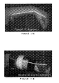
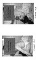
- FIG. 1 is an illustration showing the left foot of a hemiplegic patient
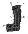
- FIG. 2 is an illustration showing the left foot of the patient illustrated in FIG. 1 wearing an ankle-foot orthotic device according to a first embodiment of the invention
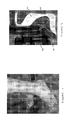
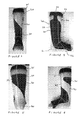
- FIG. 3 shows a front view of the orthotic device according to the first embodiment of the invention
- FIG. 4 shows an outside view of the orthotic device according to the first embodiment of the invention
- FIG. 5 shows a rear view of the orthotic device according to the first embodiment of the invention
- FIG. 6 shows an inside view of the orthotic device according to the first embodiment of the invention
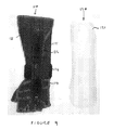
- FIG. 7 illustrates an inside view of a first portion of the orthotic device according the first embodiment of the invention
- FIG. 8 shows an inside view of a second portion of the orthotic device according to the first embodiment of the invention
- FIG. 9 illustrates a first portion and a second portion of a wrist-hand orthotic device according to a second embodiment of the invention
- FIG. 10 illustrates a side view of the orthotic device according to the second embodiment of the invention, showing the first portion and the second portion in an as-coupled state
- FIG. 11 illustrates a plan view of the orthotic device according to the second embodiment of the invention
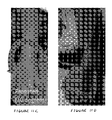
- FIGS. 11A and 11B illustrate the use of the device according to the second embodiment of the invention in correcting abnormal flexion of a patient's wrist
- FIGS. 11C and 11D illustrate the use of the device according to the second embodiment of the invention in correcting abnormal pronation of a patient's forearm
- FIGS. 11E and 11F illustrate the use of the device according to the second embodiment of the invention in correcting abnormal ulna deviation in a patient's wrist;
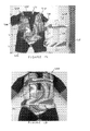
- FIG. 12 illustrates a first portion and a second portion of a thoracic orthotic device according to a third embodiment of the invention
- FIG. 13 illustrates a frontal view of the orthotic device according to the third embodiment of the invention, showing the first portion and the second portion in an as-coupled state
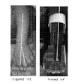
- FIGS. 13A and 13B illustrate the use of the device according to the third embodiment of the invention in correcting an abnormal lumber kyphosis
- FIG. 14 illustrates a frontal view of a pelvic orthotic device according to a fourth embodiment of the invention.
- FIG. 15 illustrates a rear view of the orthotic device according to the fourth embodiment of the invention.
- FIG. 1 illustrates the feet of a hemiplegic patient who is unable to hold their left foot 10 at an angle of 90 degrees relative to their left leg.
- the patient's right foot 11 is capable of being held at 90 degrees relative to their right leg.
- the inability to hold a foot at 90 degrees may result from a neurological dysfunction which prevents the brain and central nervous system from initiating the foot lifting action (dorsiflexion). Such dysfunction may lead to the patient's toes of their left foot dragging on the ground when they attempt to walk.
- FIG. 2 illustrates the left foot of the same patient wearing an orthotic device 20 according to a first embodiment of the invention comprising two separate couplable portions.
- the first portion 30 is a dynamic elastomeric orthosis designed to conform to a portion of the patient's foot, ankle and lower leg.
- the first portion may be described as a sock.
- the second portion 40 is a rigid polyethylene ankle brace configured to conform to a portion of the patients foot, ankle and lower leg.
- the elastomeric orthosis first portion 30 and the rigid orthosis second portion 40 are coupled together to form the orthotic device 20 .
- FIG. 2 shows that the orthotic device holds the patients left foot 10 at an angle of 90 degrees relative to their left leg.
- the orthotic device maintains the patient's ankle at a neutral position in which the foot is held at an angle of 90 degrees relative to the leg.
- the orthosis or orthotic device 20 of the first embodiment of the invention (as illustrated in FIG. 2 ) is illustrated in more detail in FIGS. 3 to 8 .
- the polyethylene ankle brace 40 has a heel portion 41 for conforming to the patient's heel, a foot portion 42 for cradling the sole of the patient's foot, and a leg portion 43 for conforming to at least a portion of the patient's lower leg.
- An upper portion 44 of the polyethylene brace 40 is configured to substantially encircle a patients leg above the calve muscle or just below the knee joint.
- the upper portion 44 of the polyethylene brace 40 does not entirely encircle the patient's leg but incorporates an opening or gap 50 to enable a patient's leg to be inserted into the brace.
- the elastomeric orthosis, or sock, 30 is formed from a lightweight breathable elastomeric fabric. Suitable fabrics are readily available, for example fabrics available under the trade names Spandex® or Lycra® may be suitable.
- panels of an underlying elastomeric material having a composition of 51% polyamide, 17% cotton and 32% Dorlastan®, are stitched together at seams such as a rear seam 39 in order to define the shape of the sock.
- the underlying material conforms to the foot, ankle, and lower leg of a wearer, but does not exert any directional forces on the ankle or foot.
- the sock 30 further comprises a number of elongated resilient dorsiflex-assist panels 31 , 32 , 33 sewn into the body of the sock over the top of the underlying elastomeric material 34 .
- the dorsiflex assist panels have a composition of 81% polyamide and 19% Lycra®, which is an elastomeric material that offers greater resistance to deformation than the underlying elastomeric material.
- a pocket 35 is defined at an upper portion of the sock. This pocket is configured to allow the upper portion 44 of the polyethylene brace 40 to be inserted within.
- the sock 30 further comprises a hook and loop fastener 36 positioned to mate with an opposing hook and loop fastener attached to the polyethylene brace (not shown).
- the polyethylene brace 40 is, thus, removably coupled to and located relative to the sock 30 by means of the upper portion 44 of the brace 40 being inserted into the pocket 35 , wherein a hook and loop fastener 36 prevents the brace 40 from sliding relative to the sock 30 .
- the upper portion 44 of the brace 40 may comprise a strap for bridging the gap 50 .
- a strap may be tightened to further secure the brace to the sock.
- Such a strap may include hook and loop fasteners (for example Velcro fasteners) or may comprise other means such as poppers or buckles.
- the strap itself may be an elastomeric strap.
- the sock 30 includes dorsiflex-assist panels 31 , 32 , 33 , which may provide a dynamic pull on the foot when the patient flexes his foot. For example, when the patient points his toes, the dorsiflex panels at the shin 31 and foot 33 are stretched. As the panel is stretched, a force is exerted pulling the foot of the patient upwardly towards the shin, pivoting around the heel. Thus the panels assist the dorsiflexion of the foot and resist plantarflexion of the foot.
- the force that is required to be exerted by the panels in order to assist dorsiflexion and resist plantarflexion will vary from patient to patient and will depend on factors such as the physical size of the patient and the level of their disability.
- the magnitude of the force may be varied as required in for any specific patient by means such as increasing the number of resilient panels that are aligned to resist dorsiflexion, changing the material that the panels are made form to a material that has a greater resilience, or increasing the thickness of the resilient panels such that they provide greater resilience.
- the sock 30 conforms to the patient's foot, ankle and lower leg and is held in position by an elastic upper seam or hem that grips the patient at the top of the calve muscle and below the knee joint.
- the polyethylene brace 40 is applied.
- the user squeezes his ankle through the gap 50 defined in the upper portion 44 of the brace 40 and slides his foot down such that the foot and heel are cradled by the foot portion 42 and heel portion 41 of the brace 40 .
- the upper portion 44 of the brace slides into the pocket 35 of the sock 30 and the hook and loop fastener 36 secures the coupling.
- the brace 40 prevents the wearer's foot from undergoing any plantarflexion beyond an angle of 90 degrees between the shin and foot.
- the sock portion 30 of the orthotic device is exerting a dorsiflexional force on the patient's foot that is continually acting and, thus, the orthotic device 20 acts simultaneously as both a static orthotic device in which the foot is prevented from plantarflexion by the brace 40 and a dynamic orthotic device in which the orthotic sock 30 is continuously exerting a dorsiflexional pull on the patient's foot.
- the orthotic sock 30 exerts a general all-round compressional force to the wearer's foot, ankle and lower leg. This compression may increase proprioception of the foot, ankle and lower leg and thus assist the wearer in learning muscle control of this portion of the body.
- Clinical usage of the orthotic device 20 may specify that the sock portion 30 of the device is worn for a predetermined number of hours per day, for example the sock portion 30 of the device may be required to be worn during a patient's normal active hours of the day.
- the polyethylene brace portion 40 of the orthotic device 20 may be coupled to, or decoupled from, the sock portion 30 as required by the patient.
- the rigid brace portion 40 may be coupled to, or decoupled from, the sock portion 30 as directed by a medical professional such as a doctor.
- the patient's foot When the rigid brace 40 is decoupled from the sock portion 30 the patient's foot is not rigidly braced and may undergo a certain degree of plantarflexion. By performing exercises or normal activities while the rigid portion is decoupled from the sock portion 30 , the patient has the opportunity to build up muscle strength and control in an attempt to improve his clinical condition.
- the brace portion may be re-coupled to the sock portion to effect a rigid bracing of the foot and ankle.
- FIGS. 9 , 10 and 11 illustrate an orthotic device according to a second embodiment of the invention. These figures show a wrist-hand orthosis or orthotic device 100 comprising two separate couplable portions.
- the first portion 110 is a dynamic elastomeric orthosis designed to conform to a portion of the patient's hand and wrist, which may be termed a glove.
- the second portion 120 is a rigid polyethylene wrist brace configured to conform to a portion of the patients wrist.
- the elastomeric orthosis portion 110 and the rigid orthosis portion 120 are coupled together to form the orthotic device 100 .
- the elastomeric orthosis 110 is in the form of a glove constructed from a lightweight elastomeric material 111 .
- the glove 110 comprises a zip opening 112 to facilitate donning the glove.
- Panels of resilient material 113 , 114 , 115 are sewn onto the underlying elastomeric material 111 to apply forces to a wearer's hand and wrist, for example to encourage supination and wrist extension.
- the underlying material is an elastomeric material having a composition of 51% polyamide, 17% cotton and 32% Dorlastan®, and the resilient panels are an elastomeric material having a composition of 81% polyamide and 19% Lycra®.
- the glove portion 110 further defines a pocket 117 for accepting a portion of the brace portion 120 of the device 100 .
- the glove portion 110 of the orthotic device 100 further comprises a strap 116 having a hook and loop fastener (a suitable example of which is commercially available as Velcro®).
- the rigid brace 120 is a custom made polyethylene brace for conforming to the wearer's wrist and lower arm and for supporting the wearer's hand.
- a patient unzips the zipper 112 on the glove portion 110 and guides his hand through an opening in the top of the glove.
- the patient's fingers are then guided through the correct finger openings and the top portion of the glove is pushed along the patient's arm until the glove is correctly positioned.
- the zipper 112 is then closed.
- the brace portion 120 is moved into position along the lower arm.
- a top end 121 of the brace 120 is inserted into the pocket 117 .
- the strap 116 is wrapped around both glove 110 and brace 120 to secure the two portions together. If further securing is required, a further strap 130 may be fastened around both portions.
- FIGS. 11A to 11F illustrate the use of the orthotic device as described above in the treatment of a patient who has a condition resulting in abnormal wrist flexion, pronation and ulna deviation.
- the patient's wrist is abnormally flexed at an angle of 45 degrees.
- the glove 110 includes panels of resilient material that resist the flexion of the wrist and, thereby, reduce the angle at which the wrist is flexed when the glove is worn.
- the rigid brace 120 is coupled to the glove 110 , as illustrated in FIG. 11B , the patient's wrist is prevented from flexing and is held in a neutral position having 10 degrees of extension. If the rigid brace 120 is de-coupled from the device the wrist may flex once more, but the flexion is resisted by the resilient panels on the glove.
- the patient's forearm is pronated by an angle of 10 degrees.
- the resilient panel 115 on the glove 110 applies a twisting force to the forearm to resist this pronation and urge the patient's forearm towards a more neutral position, as illustrated in FIG. 11D .
- the patient's wrist has an abnormal ulna deviation of 10 degrees.
- the resilient panel 114 on the glove 110 applies a force that resists this ulna deviation and urges that patient's wrist towards a more neutral position as illustrated in FIG. 11F .
- the resistive force developed by the resilient panels in any device may be determined according to the individual patient's needs. For example, a young patient may not require a glove portion that develops high resistance to correct abnormal wrist posture, whereas an adult patient may require a glove that develops a higher force.
- the thickness of panels, number of panels, and or material used to form the panels are among the parameters that may be altered in order to achieve a desired resistive force.
- FIGS. 12 and 13 illustrate an orthotic device according to a third embodiment of the invention. These figures show a thoracic lumbar orthosis or orthotic device 200 comprising two separate couplable portions.
- the first portion 210 is a dynamic elastomeric orthosis designed to conform to the torso of a patient.
- the second portion 220 is a rigid polyethylene thoracic brace configured to support the patient's spinal column.
- the elastomeric orthosis portion 210 and the rigid orthosis portion 220 are coupled together to form the orthotic device 200 .
- the elastomeric orthosis 210 is in the form of a body-suit constructed from a lightweight elastomeric material 211 .
- the suit 210 has leg holes 270 , 271 and arm holes 280 , 281 and a zippered neck opening having front 230 and rear 231 zippers to facilitate donning of the suit.
- Panels of resilient material 213 , 214 are sewn onto the underlying elastomeric material 211 to apply forces to the wearer's pelvis and spinal column, for example to apply compressive forces to the pelvis and to correct lateral curvature of the spinal column.
- the underlying material is an elastomeric material having a composition of 51% polyamide, 17% cotton and 32% Dorlastan®, and the resilient panels are an elastomeric material having a composition of 81% polyamide and 19% Lycra®.
- the suit 210 defines two pockets 217 , 218 for accepting a portion of the brace portion 220 of the device 200 .
- the thoracic brace 220 is a custom made polyethylene brace for conforming to the wearer's torso and for supporting the wearer's spinal column.
- the brace is formed as an anterior-opening shell, sufficiently flexible that a front portion can be opened to allow the brace to fit around the torso of a patient.
- the brace fastens at the patient's front.
- the brace 220 further comprises a plurality of loops 222 , which are affixed to the brace, and corresponding straps 223 for tightening the brace and for securing the brace in position coupled to the suit.
- a patient unzips the front and rear zippers 230 , 231 on the suit 210 and guides his legs through the leg-holes 270 , 271 .
- the patient slides the suit up his body until the patient's front hip bone is centred into pelvis reinforcement included in the suit. Then the patient guides his arms through the arm-holes 280 , 281 and the front and rear zippers 230 , 231 are closed.
- the patient is placed on their side.
- the shell of the brace is flexed to open it and then placed in position on the patient so that a waist roll 228 defined by the brace conforms to the waist roll of the patient.
- Left and right sides 225 , 226 to the brace shell are then inserted into the pockets 217 , 218 of the suit to locate the brace and the straps 223 are fastened to both tighten the brace and to couple the brace 220 to the suit 210 .
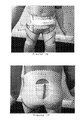
- FIGS. 13A and 13 B illustrate the use of an orthotic device according to a fourth embodiment of the invention.
- the patient illustrated in FIG. 13A has an abnormal curvature of the lower back, or lumbar kyphosis, having an angle of 45 degrees.
- the application of an orthotic device consisting of the suit 210 and brace 220 described above results in a 65 degree alteration in the angle of the lower spine, from a 45 degree lumbar kyphosis to a 20 degree lumber lordosis ( FIG. 13B ).
- FIGS. 14 and 15 illustrate an orthotic device according to a fourth embodiment of the invention.
- the first portion 310 is a dynamic elastomeric orthosis designed to conform to the pelvis of a patient.
- the second portion 320 is a rigid polyethylene pelvic brace configured to support the patient's pelvis and lumbar spinal column.
- the elastomeric orthosis portion 310 and the rigid orthosis portion 320 are coupled together to form the orthotic device 300 .
- the elastomeric orthosis 310 is in the form of orthotic shorts constructed from a lightweight elastomeric material 311 .
- the shorts 310 have leg holes 370 , 371 and a waist opening 380 for encircling a wearer's waist.
- Panels of resilient material 313 , 314 are sewn onto the underlying elastomeric material 311 to apply forces to the wearer's pelvis and groin, for example to apply compressive forces to the pelvis.
- the underlying material is an elastomeric material having a composition of 51% polyamide, 17% cotton and 32% Dorlastan®, and the resilient panels are an elastomeric material having a composition of 81% polyamide and 19% Lycra®.
- the shorts 310 define two pockets 317 , 318 for accepting a portion of the brace portion 320 of the device 300 .
- the pelvic brace 320 is a custom made polyethylene brace for conforming to the wearer's pelvis and for supporting the wearer's lower spinal column.
- the brace is formed as an anterior-opening shell, sufficiently flexible that a front portion can be opened to allow the brace to fit around the pelvis of a patient.
- the brace fastens at the patient's front.
- the brace 320 further comprises a fastening loop 322 , which is affixed to the brace, and a corresponding strap 323 for tightening the brace and for securing the brace in position coupled to the shorts.
- the shorts are donned and then the brace is positioned around the patient's waist. Left and right sides of the brace shell are then inserted into the pockets 317 , 318 of the shorts to locate the brace, and the straps 323 are fastened to both tighten the brace and to couple the brace 320 to the shorts 310 .
Landscapes
- Health & Medical Sciences (AREA)
- Vascular Medicine (AREA)
- Orthopedic Medicine & Surgery (AREA)
- Engineering & Computer Science (AREA)
- Biomedical Technology (AREA)
- Heart & Thoracic Surgery (AREA)
- Nursing (AREA)
- Life Sciences & Earth Sciences (AREA)
- Animal Behavior & Ethology (AREA)
- General Health & Medical Sciences (AREA)
- Public Health (AREA)
- Veterinary Medicine (AREA)
- Orthopedics, Nursing, And Contraception (AREA)
- Footwear And Its Accessory, Manufacturing Method And Apparatuses (AREA)
Abstract
Description
- This application claims the priority benefits of Great Britain Application No. 1015871.5, filed Sep. 21, 2010, and U.S. Provisional Patent Application Ser. No. 61/389,733, filed Oct. 5, 2010, which are hereby incorporated herein by reference.
- The invention relates to an orthotic device, in particular an orthotic device for the relief or correction of an orthopaedic or neurological condition. The invention also relates to a method for treating such conditions.
- Various conditions exist that may inhibit an individual from moving one or more of their body parts in a normal way. Such orthopaedic conditions may be congenital conditions, or may be caused as a result of injury or misuse. For example, cerebral palsy sufferers often exhibit spastic diplegia of varying degrees of severity, which adversely influences the sufferer's ability to walk normally. Treatment and management regimens for spasticity often include the use of orthoses such as splints or braces for discouraging and/or preventing poor postures and undesirable movement of body parts that may cause pain or develop into to greater disability and deformity. For example, orthoses may be employed to enable a sufferer to sit in a normal position, or to hold a sufferer's limbs in advantageous positions to improve functionality of those limbs and prevent deformities.
- Scoliosis, a lateral curvature, often coupled with vertebral rotation, of the spine, is an example of an orthopaedic condition that may be treated by an orthotic device. A typical non-surgical treatment of scoliosis involves the use of a rigid thoracic brace to hold the spine in a preferential position, thereby enabling a wearer to experience improved posture and limb functionality. Typically, treatment involves the wearing of a brace for up to 23 hours in a day. Studies have shown that such treatment may have a positive effect when the brace is worn for the prescribed periods of time. However, compliance with the prescribed treatment regimen may often be poor due to the inconvenience of wearing a rigid brace for long periods of time. Studies have shown that in some cases a brace was only worn 20% of the prescribed time, resulting in the treatment having little effect on prognosis of the scoliosis (Howton et al. 1987 orthopaedic transactions 11: 125-126).
- A rigid orthotic device such as a thoracic brace used for treatment of scoliosis, or a rigid ankle-foot orthotic device used to ameliorate the effects of spastic diplegia, only has an effect on the patient whilst the device is being worn. When the device is removed the restricted body part reverts to its undesirable condition.
- It is an aim of the invention to provide an improved orthotic device and methods of treatment.
- The invention provides an orthotic device, an elastomeric fabric orthosis, and methods of using an orthotic device as defined in the appended independent claims to which reference should now be made. Preferred and/or advantageous features of the invention are set out in various dependent sub-claims.
- Thus, a first aspect of the invention may provide an orthotic device comprising a first portion and second portion. The first portion comprises a resilient material for conforming to a portion of a wearer's body and is configured to apply a force in one or more predetermined directions to assist or restrict movement of at least one part of the wearer's body. Preferably, the force is a force for correcting or alleviating an orthopaedic or neurologic condition, particularly preferably a force having sufficient magnitude and acting in a predetermined direction such that it is capable of correcting or alleviating an orthopaedic or neurologic condition. The second portion comprises a rigid, or semi-rigid, material for restricting movement of at least one part of the wearer's body in one or more predetermined directions. The second portion is removably couplable to the first portion such that it can be removed from the first portion, or coupled to the first portion, while the first portion of the orthotic device is being worn by the wearer or patient. The first portion may act to restrict movement in the same direction as the second portion. Alternatively, or in addition, the first portion may act to restrict movement in a different direction to the second portion.
- The device is an orthotic device for assisting or restricting movement in at least at least one part of a wearer's body, which may alternatively be described as assisting or restricting movement in at least one joint in a wearer's body. The same device may act to both assist and restrict. For example, in one embodiment the device may be a device for assisting and restricting movement in a wearer's ankle. The first portion may apply a force that promotes, for example, dorsiflexion of the wearer's foot and the second portion may be configured to restrict or prevent plantarflexion of the wearer's foot.
- Rigid orthotic devices have been worn in conjunction with garments to improve the comfort of the wearer, or with liners designed to improve comfort and allow sweat to be conveyed away from the wearer's skin. Such liners or garments did not apply a force in one or more predetermined directions to assist or restrict movement of a portion of the wearer's body.
- Preferably the first portion comprises a base elastomeric material or underlying elastomeric material that may conform to the wearer's body. The underlying elastomeric material is preferably multidirectionably stretchable, i.e. the underlying material is capable of conforming to the desired portion of the wearer's body but does not generate overall forces, or give rise to lines of tension or compression, in any specific direction. The underlying elastomeric material of the first portion is preferably formed from any such suitable elastomeric material, for example materials comprising a polyurethane-polyurea copolymer such as Dorlastan®, Spandex®, or Lycra®. A particularly suitable material may be a polyamide-cotton-Dorlastan® material, for example a material comprising 51% polyamide, 17% cotton and 32% Dorlastan®.
- Preferably the first portion further comprises a resilient means for applying a force acting in one or more predetermined directions to assist and/or restrict movement of at least one part of the wearer's body. Particularly preferably, the resilient means comprises one or more strips or panels of resilient material or elastic material that are attached to the base/underlying elastomeric material of the first portion to provide a tension force or compression force to a portion of the wearer's body. For example, the resilient means may be one or more elongated strips or panels of a resilient material such as a nylon/cotton material or a nylon/Lycra® material, for example a material comprising 81% polyamide and 19% Lycra®.
- Additional resilient strips or panels may be attached to the first portion so that they overlay existing resilient strips or panels. Thus, reference in this document to attaching resilient means, strips or panels to the first portion of the device includes the attachment of resilient means, strips or panels to a base/underlying elastomeric material, and also to the attachment of a resilient means, strips or panels to a first portion that has existing resilient means, strips or panels attached.
- The resilient means, for example one or more resilient strips or panels, may provide a constant force to a portion of the wearer's body that urges that portion of the wearer's body in a specific direction. The resilient means may provide a force that resists movement of the wearer's body when the wearer moves that portion of their body in a specific direction.
- In preferred embodiments, panels or strips of resilient material may be attached to the first portion in a non-tensioned condition, i.e. the panels or strips do not have a force applied to them as they are attached to the underlying material and do not exert a force on the underlying material. In this configuration each panel or strip may, when the first portion of the device is worn, apply a resistive force acting in a specific direction when a portion of a wearer's body is moved in a direction that causes the panel or strip to stretch. The force generated by an individual strip or panel is preferably applied to the wearer's body in the direction of a longitudinal axis of the strip or panel. More than one strip or panel may be used in conjunction such that the sum of the forces applied by the strips or panels results in a net force that is applied to the wearer's body in a direction that is not coincident with a longitudinal axis of any one panel or strip.
- Advantageously, panels or strips of resilient material may be attached to the first portion such that they become stretched when the first portion is worn by a wearer. Thus, the resilient panels or strips may, once the first portion has been donned by a wearer, provide a continuous force urging a portion of the wearer's body in a predetermined direction.
- In some embodiments, one or more strips or panels of resilient material may be attached to the first portion in a pre-tensioned condition, i.e. the panels or strips are stretched and then attached to the underlying material while stretched. In this configuration the panels or strips are able to exert a force on a wearer's body that continually urges the wearer's body in the direction of the applied force. The force generated by a pre-tensioned strip or panel will resist movement of a wearer's body in a direction that causes the strip or panel to stretch further.
- A first portion of an orthotic device as described herein may advantageously comprise both tensioned and non-tensioned panels or strips to generate forces that assist or restrict movement of the wearer's body in a predetermined direction.
- The force applied by the resilient means, for example a force applied by a resilient strip or panel, is preferably a force that has an orthotic effect on the wearer or a clinical effect on the wearer. For example, the force is preferably a force capable of assisting or restricting movement of a portion of a wearer's body in order to correct or alleviate an orthopaedic or neurologic condition. Thus, it is preferable that the magnitude of the force and the direction the force is applied in is sufficient to straighten or assist the movement of a portion of a wearer's body such that an orthopaedic or neurologic condition is corrected or alleviated. The magnitude or strength of this force may depend on the disability or abnormality the orthotic device is designed to correct, and the portion of the body that the orthotic device is intended to treat. For example, in an orthotic device for encouraging supination of an infant's wrist the force provided by the first portion of the device to achieve this aim may be slight. Alternatively, in an orthotic device for treating scoliosis in an adult patient the force required to straighten the spine may be high. The magnitude of force and the predetermined direction, or directions, in which the force is applied are preferably determined by a medical professional, preferably on a case-by-case basis.
- The first portion may itself be a fully functional dynamic elastomeric fabric orthosis or dynamic movement orthosis for providing a functional orthotic effect on a wearer's body. For example, the first portion may, when worn, provide an orthotic effect that preferentially restricts or assists movement in a portion of the wearer's body in order to treat or manage a disability, deformity or weakness. Thus, the first portion may be an elastomeric orthosis for conforming to a wearer's ankle or lower leg or knee or for conforming to the pelvis or torso of a wearer or the shoulder or elbow or wrist and/or one or more fingers or a wearer.
- In preferred embodiments the first portion may be a custom designed or bespoke orthosis and may be prepared according to measurements taken by a medical professional.
- By conforming to a portion of the wearer's body the first portion of the orthotic device may exert a slight compressive force to the portion of the wearer's body and this force may advantageously increase the wearer's proprioception of that portion of their body. Proprioception may make an important contribution to a patient's unconscious awareness of a portion of their own body. When wearing certain embodiments of the invention, such as an elastomeric orthotic device for conforming to the pelvic region of a wearer, an improved sense of proprioception may improve the stability of a wearer.
- Furthermore, by conforming to a portion of the wearer's body the first portion of the orthotic device may be described as adhering to or gripping the skin of the wearer. This may assist in the transfer of any forces from the resilient strips to a patients joint. For example, if the first portion of the orthotic device includes resilient strips of material that act to provide a rotational force on a limb, this force may be more efficiently transferred if the first portion effectively adheres to the skin of the wearer.
- Preferably the orthotic device comprises means for coupling the first portion with the second portion. The means for coupling may be incorporated in the first portion or the means for coupling may be incorporated in the second portion. It may be advantageous for the means for coupling to be incorporated in both the first and second portions.
- Suitable means for coupling may include a fastener or a strap combined with a fastener. Thus the means for coupling may comprise a strap for holding the second portion relative to the first portion and a fastener for securing the strap, for example a hook and loop fastener, a popper, a button, a zip, a magnetic fastener, or a buckle.
- It is preferable that the second portion is carefully positioned at a predetermined orientation with respect to the wearer's body. It may, thus, be advantageous that the orthotic device comprises a means for locating the second portion in a predetermined position with respect to the first portion. Thus, the first portion may conform to a portion of the wearer's body and then the second portion may be located with respect to this first portion and, thus, located with a respect to a portion of the wearer's body. Preferable means for locating the second portion may comprise a pocket or a slit defined in the first portion, in which at least part of the second portion is insertable into the pocket or slit in order to locate the second portion with respect to the first portion.
- The means for coupling the first portion to the second portion may include the means for locating the second portion relative to the first portion. Thus, a means for coupling the second portion to the first portion may incorporate a pocket or slit defined within the first portion. The means for coupling may additionally comprise other elements such as loops or straps to secure the second portion relative to the first portion.
- Preferably the second portion comprises an orthotic support or brace. Such a brace may be formed from any suitable rigid or semi-rigid material, for example a polymeric material such as polyethylene or polypropylene. Polymeric materials suitable for forming an orthotic brace may include various copolymers of polyethylene and/or polypropylene, modified polyethylenes, and modified polyethylene copolymers. Suitable polymeric materials may also include various thermoplastics, for example polymers that may be deformed into a new shape on application of a certain temperature, for example after immersing in hot water. Suitable polymeric materials may also include resin based cast polymers.
- Other suitable materials for the forming of a brace may include composite structures such a glass-fibre composite or a carbon-fibre composite or lightweight metallic alloy materials. Other materials may be used to form an orthotic support or brace and such materials will be apparent to the skilled person.
- Preferably the second portion of the orthotic device is shaped to conform to the portion of the wearer's body. For example if the orthotic device is an orthotic device for assisting and/or restricting movement of a wearers foot (i.e. an ankle-foot orthosis or AFO) then the second portion may be a rigid or semi-rigid brace that conforms to a portion of the wearers lower leg and heel and prevents movement of the foot in a predetermined direction, for example the second portion may prevent a wearer from pointing his or her toes.
- In preferred embodiments the second portion may be a custom designed or bespoke support or brace and may be prepared according to measurements taken by a medical professional.
- The second portion may be formed from more than one rigid or semi-rigid component. For example, it may be advantageous for the second portion to be articulated or hinged so that the portion is capable of flexing in one direction but not flexing in another direction. Hinged and articulated rigid braces are known in the art.
- A preferred embodiment of an orthotic device according to the invention may be an ankle-foot orthosis, in which the first portion is an orthotic sock configured to assist or restrict movement of the wearer's foot in one or more predetermined directions and the second portion is a rigid brace for restricting movement of the wearer's foot in one more predetermined directions. The sock may have an upper portion for encircling a lower portion of the wearer's leg and a slit or a pocket may be defined in this upper portion for receiving part of the brace in order to locate the brace relative to the sock.
- The first portion may incorporate one or more resilient panels to apply forces in different predetermined directions to the wearer's foot. For example the sock may comprise one or more anterior panels of resilient material extending along a shin portion and an upper foot portion of the sock in order to assist the dorsiflexion of the wearer's foot and simultaneously resist plantarflexion and pronation. The brace may rigidly prevent plantarflexion of the wearer's foot.
- A preferred embodiment of an orthotic device according to the invention may be a pelvic orthosis in which the first portion is a pair of orthotic shorts configured to apply a force in a predetermined direction to compress one or more of the pelvic joints, i.e. to restrict movement of parts of the pelvis, and the second portion is a brace for restricting movement of one or more of the pelvic joints.
- Preferably the shorts define one or more pockets or slits for receiving part of the brace to locate the brace in position relative to the shorts and thereby relative to the pelvis.
- A preferred embodiment of an orthotic device according to the invention may be a spinal orthosis or a thoracic lumbar orthosis in which the first portion is a resilient suit configured to apply a directional force to the wearer's spinal column and the second portion is a brace for restricting movement of the wearer's spinal column. Preferably the suit defines one or more pockets or slits for receiving part of the brace in order to locate the brace relative to the suit.
- A preferred embodiment of an orthotic device according to the invention may be a wrist-hand orthosis in which the first portion is a glove configured to assist or restrict movement of the wearer's hand in one or more predetermined directions and the second portion is a brace for restricting movement of the wearer's hand. For example, the first portion may incorporate one or more resilient panels designed to encourage movements such as supination, pronation, wrist extension and/or radial/ulna deviation. Preferably the glove defines one or more slits or pockets for receiving part of the brace to locate the brace relative to the glove.
- Thus, it is preferred that the first portion of the orthotic device is a functional resilient or elastomeric orthosis configured to apply a functional orthotic force in one or more predetermined directions to a portion of the wearer's body and that the second portion is a functional rigid or semi-rigid orthosis for resisting movement of at least one portion of the wearer's body. A wearer may be able to wear the first and second portions of the orthotic device in combination in order to restrict movement of a predetermined part of their body in order to improve, for example, posture or limb function, or in order to relieve pain associated with an orthopaedic disorder. When used in this configuration the first portion may advantageously locate the second portion in an optimum position for the functioning of the second portion. The first portion may also, advantageously, increase proprioception of the portion of the wearer's body by applying a compressive force to that portion of the wearer's body.
- Rigid braces are efficient at restricting extension or flexion of a joint. However, they are less efficient at restriction rotational movement of a joint as it is difficult to couple the rigid brace to a patient's limb in a manner that restricts rotation without discomfort. An orthotic device as described herein may be advantageous for use with patients requiring a restriction in rotational movement of a joint. As described above, the first portion may grip or adhere to the skin of a wearer or patient. When coupled to a second portion that comprises a rigid brace configured to restrict movement of a joint beyond a particular rotational angle, the first portion may grip the skin sufficiently for the rigid bracing to be effective without excessive patient discomfort. Furthermore, the first portion may comprise resilient strips or panels that act to assist or restrict rotational movement in order to provide the desired rotational correction to the particular joint.
- As a specific example, an orthotic device designed for a patient's wrist may be designed to restrict supination of the patient's forearm. This restriction may be achieved simply by the position at which the rigid second portion couples to the dynamic first portion (i.e. the rigid portion is shaped to restrict rotation, and the position at which the second portion couples to the first portion holds the wrist in the desired position relative to the second portion), it may be achieved by the use of resilient panels on the first portion that restrict supination of the forearm, or there may be a combination of both of these aspects. For such situations, the use of a device that couples both dynamic and rigid elements may provide a distinct advantage over a dynamic or rigid device alone.
- It may be particularly advantageous that the second, rigid, portion of the device is primarily designed to prevent flexion or extension of a joint beyond a predetermined angle, and the first, dynamic, portion of the device acts to assist or restrict movement of the same joint in other directions than that restricted by the second portion. For clarity, the first portion may also assist or restrict flexion or extension of the joint. Thus, using an orthotic device designed for a wrist as an example, the second portion may be designed to rigidly hold the wrist at a predetermined extension, say 10 degrees. The second portion may incorporate resilient strips that also encourage extention of the wrist, and in addition, the second portion may include resilient strips that encourage the pronation or supination of the patient's forearm and/or resilient strips that encourage the radial deviation or ulna deviation of the wrist.
- Advantageously, the second portion may be decoupled from or removed from the first portion. Unlike prior art orthotic devices, removal of the second portion (which preferably functions as an orthotic brace) does not result in the loss of functional orthotic support of the wearer's body. The wearer may remove the second portion in order to provide some comfort and respite from wearing a rigid brace, or in order to perform specific therapeutic exercises. When the second portion is removed the first portion still acts on the wearer's body. Thus, non-compliance with a prescribed regimen of wearing the rigid portion of the device may not be as detrimental to the treatment as in the prior art example of non-compliance.
- Recent research into dynamic elastomeric orthoses has indicated that such orthoses may provide a number of beneficial effects not provided by rigid orthoses. In addition to the benefit that may be provided by increased proprioception of a portion of the wearer's body, dynamic elastomeric orthoses may allow a wearer or patient to develop specific muscle control or build up muscle tone in order to counteract orthotic complaints or problems. For example, the use of dynamic elastomeric orthoses in the treatment of scoliosis has indicated that patients may develop the ability to hold their bodies in preferred postures after a period of treatment, even when their dynamic orthosis has been removed. In patients treated by rigid orthoses no such ability is developed due to inactivity of the underlying muscles initiated by the immobile restriction of the spinal brace.
- The use of a resilient orthotic device that applies force in one or more predetermined directions may facilitate the development of preferential muscle structures in the body, for example by allowing the wearer to perform suitable exercises while wearing the orthosis.
- Furthermore, a dynamic orthoses may influence the wearer by exerting a continuous force or forces to the body portion on which the dynamic orthotic is being worn. Thus, it may be that the first portion of the orthotic device provides a beneficial orthotic effect when worn in combination with the second portion of the device. The second portion, for example, may rigidly prevent movement of a portion of the wearer's body and, simultaneously, the first portion may provide a continuous force or pressure that positively influences the long term recovery of the wearer.
- For wearers who are prescribed various exercise regimes to assist management of their condition, or to assist recovery from their condition, an orthotic device according to the invention may advantageously allow the second (rigid or semi-rigid) portion of the device to be decoupled such that the patient can perform exercises whilst wearing only the first (resilient) portion of the device.
- A second aspect the invention may provide an elastomeric fabric orthosis configured to apply a force in one or more predetermined directions to assist or restrict movement in at least one part of a wearer's body, or in at least one joint of a wearer's body, in which the fabric orthosis comprises means for locating a rigid or semi-rigid orthosis in position with respect to the dynamic elastomeric fabric orthosis.
- Preferably the means for locating the rigid or semi-rigid orthosis comprises one or more slits or pockets for receiving at least a portion of the rigid or semi-rigid orthosis.
- Preferably the elastomeric orthoses further comprises coupling means for removably coupling the rigid or semi-rigid orthosis with the elastomeric orthosis. Such coupling means may comprise a fastener, or loops or straps in combination with a fastener. A suitable fastener may be selected from the group comprising a hook and loop fastener, a popper, a zip, a button, a magnetic fastener, and a buckle. Thus, an elastomeric fabric orthosis according to the second aspect of the invention may be a functional elastomeric fabric orthosis that comprises a means for locating a functional rigid or semi-rigid orthosis.
- An elastomeric fabric orthosis according to the second aspect of the invention may form the first portion of an orthotic device according to the first aspect of the invention.
- A third aspect of the invention may provide a rigid or semi-rigid orthosis adapted to be removably coupled to an elastomeric fabric orthosis. The rigid or semi-rigid orthosis may comprise means for removably coupling the rigid or semi-rigid orthosis to an elastomeric fabric orthosis. The rigid or semi-rigid orthosis may comprise means, such as lugs, for engaging with an elastomeric fabric orthosis in order to locate the rigid or semi-rigid orthosis with respect to the fabric orthosis.
- A rigid or semi-rigid orthosis according to the third aspect of the invention may be used a second portion of an orthotic device according to the first aspect of the invention.
- A fourth aspect the invention may provide a method of using an orthotic device comprising a first portion and a second portion. The first portion comprises a resilient material for conforming to a portion of the wearer's body and the second portion comprises a rigid or semi-rigid material. A method according to the fourth aspect comprises the steps of donning the first portion of the orthotic device and then coupling the second portion of the orthotic device to the first portion of the orthotic device.
- The method may be a convenient method of providing a patient with a rigid orthotic support.
- Preferably the method comprises a step of inserting at least a part of the second portion of the orthotic device into a slit or pocket defined in the first portion or the orthotic device to locate the second portion relative to the first portion. The resilient first portion conforms to a portion of the wearer's body and, thus, may provide a convenient means for locating the second portion of the orthotic device in an appropriate position to have a beneficial effect on the wearer
- Particularly preferably, the method may comprise the step of releasably fastening a strap to couple the second portion to the first portion.
- It may be advantageous that the second portion is removably couplable to the first portion. Thus the method may comprise a step in which the second portion is uncoupled from the first portion and removed from the orthotic device after a period of time has passed. This period of time may be a clinically prescribed period of time in which the first portion and the second portion of the orthotic device are worn together in combination. The period of time may, alternatively, be a period of time in which the first portion and the second portion are worn in combination and after which the wearer wishes to remove the rigid second portion.
- It may, thus, be advantageous that the first portion of the orthotic device can be worn separately from the second portion of the orthotic device for a period of time. This period of time may also be a clinically prescribed period of time.
- The method may further comprise the step of re-coupling the second portion to the first portion.
- A fifth aspect of the invention may provide a method of supporting, aligning, or assisting the movement of a movable part of a wearer's or patient's body. The method according to the fifth aspect may comprise the steps of dressing the patient (wearer) in a resilient orthosis configured to apply a force in one or more predetermined directions to assist or restrict movement of the movable part of the patient's body, and coupling a brace formed from a rigid or semi-rigid material for restricting movement of the movable part of the patients body to the resilient orthosis. The resilient orthosis and the brace are worn by the patient, in combination, for a period of time.
- The method may further comprise the step of decoupling the brace from the resilient orthosis such that the resilient orthosis is worn by the patient separately from the brace for a period of time.
- The method may provide the further step of re-coupling the brace to the resilient orthosis such that the resilient orthosis and the brace are worn in combination for a further period of time. The resilient orthosis and the brace may form, in combination, an orthotic device as described above.
- The periods of time in which the resilient orthosis and the brace are worn in combination and the periods of time in which the resilient orthosis is worn separately from the base may be periods of time that are prescribed by a clinician to treat or manage a particular condition.
- The method may be of use in many orthopaedic and/or neurological conditions, for example for treating neurological dysfunctions caused as a result of cerebral palsy, strokes, head injuries, multiple sclerosis, and other neurological conditions. As an example, the treatment of hemiplegia, diplegia, or other forms of spasticity may be treated by the use of a combination of a resilient pelvic orthosis with a rigid pelvic brace or by the combination of resilient orthotic socks with a rigid ankle brace. The treatment of hemiplegia, quadriplegia, cerebral vascular accidents, trauma, multiple sclerosis, and Parkinson's disease may involve the use of a resilient orthotic glove in combination with a rigid wrist brace. The treatment of low thoracic muscular tone, hyper-kyphosis of the thoracic spine, aspects of cerebral palsy, and neuropathic scoliosis may be treated by the use of a resilient thoracic orthosis in combination with a rigid thoracic brace.
- The method of treatment of a specific condition may include instructions that the brace is to be worn in combination with the resilient orthosis for a predetermined proportion of the total time that the resilient orthosis is worn. Thus, it may be specified that the resilient orthosis is worn in combination with the brace for a proportion of 90% of the total time that the resilient orthosis is worn (or other proportions, for example or 80% or 70% of the time).
- Advantageously, the predetermined portion of time may be altered as part of a course of treatment. Thus, the method may comprise a treatment regimen in which the resilient orthosis and the brace are worn together in combination for a high proportion of the time at the start of the treatment and this proportion of the time is progressively reduced as the treatment progresses.
- The method of treatment may, thus, proceed to a point in which the brace is worn in combination with the resilient orthosis for only a low proportion of the total time that the resilient orthosis is worn, for example less than 10% of the time. The method may ultimately dispense with the use of the brace if the patient progresses sufficiently for the resilient orthosis to be worn without the brace.
-
FIG. 1 is an illustration showing the left foot of a hemiplegic patient; -
FIG. 2 is an illustration showing the left foot of the patient illustrated inFIG. 1 wearing an ankle-foot orthotic device according to a first embodiment of the invention; -
FIG. 3 shows a front view of the orthotic device according to the first embodiment of the invention; -
FIG. 4 shows an outside view of the orthotic device according to the first embodiment of the invention; -
FIG. 5 shows a rear view of the orthotic device according to the first embodiment of the invention; -
FIG. 6 shows an inside view of the orthotic device according to the first embodiment of the invention; -
FIG. 7 illustrates an inside view of a first portion of the orthotic device according the first embodiment of the invention, -
FIG. 8 shows an inside view of a second portion of the orthotic device according to the first embodiment of the invention, -
FIG. 9 illustrates a first portion and a second portion of a wrist-hand orthotic device according to a second embodiment of the invention, -
FIG. 10 illustrates a side view of the orthotic device according to the second embodiment of the invention, showing the first portion and the second portion in an as-coupled state, -
FIG. 11 illustrates a plan view of the orthotic device according to the second embodiment of the invention, -
FIGS. 11A and 11B illustrate the use of the device according to the second embodiment of the invention in correcting abnormal flexion of a patient's wrist; -
FIGS. 11C and 11D illustrate the use of the device according to the second embodiment of the invention in correcting abnormal pronation of a patient's forearm; -
FIGS. 11E and 11F illustrate the use of the device according to the second embodiment of the invention in correcting abnormal ulna deviation in a patient's wrist; -
FIG. 12 illustrates a first portion and a second portion of a thoracic orthotic device according to a third embodiment of the invention, -
FIG. 13 illustrates a frontal view of the orthotic device according to the third embodiment of the invention, showing the first portion and the second portion in an as-coupled state, -
FIGS. 13A and 13B illustrate the use of the device according to the third embodiment of the invention in correcting an abnormal lumber kyphosis; -
FIG. 14 illustrates a frontal view of a pelvic orthotic device according to a fourth embodiment of the invention, and -
FIG. 15 illustrates a rear view of the orthotic device according to the fourth embodiment of the invention. -
FIG. 1 illustrates the feet of a hemiplegic patient who is unable to hold theirleft foot 10 at an angle of 90 degrees relative to their left leg. By comparison, it can be seen that the patient's right foot 11 is capable of being held at 90 degrees relative to their right leg. The inability to hold a foot at 90 degrees may result from a neurological dysfunction which prevents the brain and central nervous system from initiating the foot lifting action (dorsiflexion). Such dysfunction may lead to the patient's toes of their left foot dragging on the ground when they attempt to walk. -
FIG. 2 illustrates the left foot of the same patient wearing anorthotic device 20 according to a first embodiment of the invention comprising two separate couplable portions. Thefirst portion 30 is a dynamic elastomeric orthosis designed to conform to a portion of the patient's foot, ankle and lower leg. The first portion may be described as a sock. Thesecond portion 40 is a rigid polyethylene ankle brace configured to conform to a portion of the patients foot, ankle and lower leg. The elastomeric orthosisfirst portion 30 and the rigid orthosissecond portion 40 are coupled together to form theorthotic device 20. -
FIG. 2 shows that the orthotic device holds the patients leftfoot 10 at an angle of 90 degrees relative to their left leg. In other words, the orthotic device maintains the patient's ankle at a neutral position in which the foot is held at an angle of 90 degrees relative to the leg. - The orthosis or
orthotic device 20 of the first embodiment of the invention (as illustrated inFIG. 2 ) is illustrated in more detail inFIGS. 3 to 8 . - The
polyethylene ankle brace 40 has a heel portion 41 for conforming to the patient's heel, afoot portion 42 for cradling the sole of the patient's foot, and aleg portion 43 for conforming to at least a portion of the patient's lower leg. An upper portion 44 of thepolyethylene brace 40 is configured to substantially encircle a patients leg above the calve muscle or just below the knee joint. - The upper portion 44 of the
polyethylene brace 40 does not entirely encircle the patient's leg but incorporates an opening orgap 50 to enable a patient's leg to be inserted into the brace. - The elastomeric orthosis, or sock, 30 is formed from a lightweight breathable elastomeric fabric. Suitable fabrics are readily available, for example fabrics available under the trade names Spandex® or Lycra® may be suitable. In the first embodiment panels of an underlying elastomeric material, having a composition of 51% polyamide, 17% cotton and 32% Dorlastan®, are stitched together at seams such as a rear seam 39 in order to define the shape of the sock. The underlying material conforms to the foot, ankle, and lower leg of a wearer, but does not exert any directional forces on the ankle or foot. The
sock 30 further comprises a number of elongated resilient dorsiflex-assistpanels elastomeric material 34. The dorsiflex assist panels have a composition of 81% polyamide and 19% Lycra®, which is an elastomeric material that offers greater resistance to deformation than the underlying elastomeric material. - A
pocket 35 is defined at an upper portion of the sock. This pocket is configured to allow the upper portion 44 of thepolyethylene brace 40 to be inserted within. Thesock 30 further comprises a hook andloop fastener 36 positioned to mate with an opposing hook and loop fastener attached to the polyethylene brace (not shown). Thepolyethylene brace 40 is, thus, removably coupled to and located relative to thesock 30 by means of the upper portion 44 of thebrace 40 being inserted into thepocket 35, wherein a hook andloop fastener 36 prevents thebrace 40 from sliding relative to thesock 30. - The upper portion 44 of the
brace 40 may comprise a strap for bridging thegap 50. Such a strap may be tightened to further secure the brace to the sock. Such a strap may include hook and loop fasteners (for example Velcro fasteners) or may comprise other means such as poppers or buckles. The strap itself may be an elastomeric strap. - In use, a patient first dons the
orthotic sock 30 portion of theorthotic device 20. Thesock 30 includes dorsiflex-assistpanels shin 31 andfoot 33 are stretched. As the panel is stretched, a force is exerted pulling the foot of the patient upwardly towards the shin, pivoting around the heel. Thus the panels assist the dorsiflexion of the foot and resist plantarflexion of the foot. - It is noted that the force that is required to be exerted by the panels in order to assist dorsiflexion and resist plantarflexion will vary from patient to patient and will depend on factors such as the physical size of the patient and the level of their disability. The magnitude of the force may be varied as required in for any specific patient by means such as increasing the number of resilient panels that are aligned to resist dorsiflexion, changing the material that the panels are made form to a material that has a greater resilience, or increasing the thickness of the resilient panels such that they provide greater resilience.
- The
sock 30 conforms to the patient's foot, ankle and lower leg and is held in position by an elastic upper seam or hem that grips the patient at the top of the calve muscle and below the knee joint. - After the
sock portion 30 has been correctly donned, thepolyethylene brace 40 is applied. The user squeezes his ankle through thegap 50 defined in the upper portion 44 of thebrace 40 and slides his foot down such that the foot and heel are cradled by thefoot portion 42 and heel portion 41 of thebrace 40. The upper portion 44 of the brace slides into thepocket 35 of thesock 30 and the hook andloop fastener 36 secures the coupling. - The
brace 40 prevents the wearer's foot from undergoing any plantarflexion beyond an angle of 90 degrees between the shin and foot. In addition, thesock portion 30 of the orthotic device is exerting a dorsiflexional force on the patient's foot that is continually acting and, thus, theorthotic device 20 acts simultaneously as both a static orthotic device in which the foot is prevented from plantarflexion by thebrace 40 and a dynamic orthotic device in which theorthotic sock 30 is continuously exerting a dorsiflexional pull on the patient's foot. - In addition to the dorsiflexion force, the
orthotic sock 30 exerts a general all-round compressional force to the wearer's foot, ankle and lower leg. This compression may increase proprioception of the foot, ankle and lower leg and thus assist the wearer in learning muscle control of this portion of the body. - Clinical usage of the
orthotic device 20 may specify that thesock portion 30 of the device is worn for a predetermined number of hours per day, for example thesock portion 30 of the device may be required to be worn during a patient's normal active hours of the day. Thepolyethylene brace portion 40 of theorthotic device 20 may be coupled to, or decoupled from, thesock portion 30 as required by the patient. Alternatively, therigid brace portion 40 may be coupled to, or decoupled from, thesock portion 30 as directed by a medical professional such as a doctor. - When the
rigid brace 40 is decoupled from thesock portion 30 the patient's foot is not rigidly braced and may undergo a certain degree of plantarflexion. By performing exercises or normal activities while the rigid portion is decoupled from thesock portion 30, the patient has the opportunity to build up muscle strength and control in an attempt to improve his clinical condition. - As a patient's foot tires, for example after exercise or after a prolonged period of time with the sock portion being worn individually without the brace, the brace portion may be re-coupled to the sock portion to effect a rigid bracing of the foot and ankle.
- It may be advantageous for a patient to increase, over a period of weeks or months, the proportion of each day that they spend wearing the
orthotic device 20 with therigid brace portion 40 decoupled from theorthotic sock portion 30. -
FIGS. 9 , 10 and 11 illustrate an orthotic device according to a second embodiment of the invention. These figures show a wrist-hand orthosis ororthotic device 100 comprising two separate couplable portions. Thefirst portion 110 is a dynamic elastomeric orthosis designed to conform to a portion of the patient's hand and wrist, which may be termed a glove. Thesecond portion 120 is a rigid polyethylene wrist brace configured to conform to a portion of the patients wrist. Theelastomeric orthosis portion 110 and therigid orthosis portion 120 are coupled together to form theorthotic device 100. - The
elastomeric orthosis 110 is in the form of a glove constructed from a lightweight elastomeric material 111. Theglove 110 comprises azip opening 112 to facilitate donning the glove. Panels of resilient material 113,114, 115 are sewn onto the underlying elastomeric material 111 to apply forces to a wearer's hand and wrist, for example to encourage supination and wrist extension. The underlying material is an elastomeric material having a composition of 51% polyamide, 17% cotton and 32% Dorlastan®, and the resilient panels are an elastomeric material having a composition of 81% polyamide and 19% Lycra®. - The
glove portion 110 further defines apocket 117 for accepting a portion of thebrace portion 120 of thedevice 100. - The
glove portion 110 of theorthotic device 100 further comprises astrap 116 having a hook and loop fastener (a suitable example of which is commercially available as Velcro®). - The
rigid brace 120 is a custom made polyethylene brace for conforming to the wearer's wrist and lower arm and for supporting the wearer's hand. - In use, a patient unzips the
zipper 112 on theglove portion 110 and guides his hand through an opening in the top of the glove. The patient's fingers are then guided through the correct finger openings and the top portion of the glove is pushed along the patient's arm until the glove is correctly positioned. Thezipper 112 is then closed. - The patient's wrist is then held at the desired position and the
brace portion 120 is moved into position along the lower arm. Atop end 121 of thebrace 120 is inserted into thepocket 117. With thebrace 120 in the correct position, thestrap 116 is wrapped around bothglove 110 and brace 120 to secure the two portions together. If further securing is required, afurther strap 130 may be fastened around both portions. -
FIGS. 11A to 11F illustrate the use of the orthotic device as described above in the treatment of a patient who has a condition resulting in abnormal wrist flexion, pronation and ulna deviation. - As illustrated in
FIG. 11A , the patient's wrist is abnormally flexed at an angle of 45 degrees. Theglove 110 includes panels of resilient material that resist the flexion of the wrist and, thereby, reduce the angle at which the wrist is flexed when the glove is worn. When therigid brace 120 is coupled to theglove 110, as illustrated inFIG. 11B , the patient's wrist is prevented from flexing and is held in a neutral position having 10 degrees of extension. If therigid brace 120 is de-coupled from the device the wrist may flex once more, but the flexion is resisted by the resilient panels on the glove. - As illustrated in
FIG. 11C , the patient's forearm is pronated by an angle of 10 degrees. The resilient panel 115 on theglove 110 applies a twisting force to the forearm to resist this pronation and urge the patient's forearm towards a more neutral position, as illustrated inFIG. 11D . - As illustrated in
FIG. 11E , the patient's wrist has an abnormal ulna deviation of 10 degrees. The resilient panel 114 on theglove 110 applies a force that resists this ulna deviation and urges that patient's wrist towards a more neutral position as illustrated inFIG. 11F . - The resistive force developed by the resilient panels in any device may be determined according to the individual patient's needs. For example, a young patient may not require a glove portion that develops high resistance to correct abnormal wrist posture, whereas an adult patient may require a glove that develops a higher force. The thickness of panels, number of panels, and or material used to form the panels are among the parameters that may be altered in order to achieve a desired resistive force.
- Although this specific embodiment illustrates the use of a device to treat a patient presenting abnormal flexion and ulna deviation of the wrist along with abnormal pronation of the forearm, it is clear that the invention may be utilized for the correction of other issues. For example, if the patient suffered from an abnormal extension of the wrist, resilient panels would be positions to counter this extention. Likewise, the patient may suffer from radial deviation of the wrist and/or forearm supination. Resilient panels may be positioned on the glove at suitable orientations to counteract these conditions.
-
FIGS. 12 and 13 illustrate an orthotic device according to a third embodiment of the invention. These figures show a thoracic lumbar orthosis ororthotic device 200 comprising two separate couplable portions. Thefirst portion 210 is a dynamic elastomeric orthosis designed to conform to the torso of a patient. The second portion 220 is a rigid polyethylene thoracic brace configured to support the patient's spinal column. Theelastomeric orthosis portion 210 and the rigid orthosis portion 220 are coupled together to form theorthotic device 200. - The
elastomeric orthosis 210 is in the form of a body-suit constructed from a lightweight elastomeric material 211. Thesuit 210 has leg holes 270, 271 andarm holes 280, 281 and a zippered neckopening having front 230 and rear 231 zippers to facilitate donning of the suit. Panels of resilient material 213, 214 are sewn onto the underlying elastomeric material 211 to apply forces to the wearer's pelvis and spinal column, for example to apply compressive forces to the pelvis and to correct lateral curvature of the spinal column. The underlying material is an elastomeric material having a composition of 51% polyamide, 17% cotton and 32% Dorlastan®, and the resilient panels are an elastomeric material having a composition of 81% polyamide and 19% Lycra®. - The
suit 210 defines twopockets 217, 218 for accepting a portion of the brace portion 220 of thedevice 200. - The thoracic brace 220 is a custom made polyethylene brace for conforming to the wearer's torso and for supporting the wearer's spinal column. The brace is formed as an anterior-opening shell, sufficiently flexible that a front portion can be opened to allow the brace to fit around the torso of a patient. The brace fastens at the patient's front.
- The brace 220 further comprises a plurality of loops 222, which are affixed to the brace, and corresponding
straps 223 for tightening the brace and for securing the brace in position coupled to the suit. - In use, a patient unzips the front and
rear zippers suit 210 and guides his legs through the leg-holes holes 280, 281 and the front andrear zippers - To couple the
suit portion 210 and the brace portion 220, the patient is placed on their side. The shell of the brace is flexed to open it and then placed in position on the patient so that a waist roll 228 defined by the brace conforms to the waist roll of the patient. Left andright sides pockets 217, 218 of the suit to locate the brace and thestraps 223 are fastened to both tighten the brace and to couple the brace 220 to thesuit 210. -
FIGS. 13A and 13 B illustrate the use of an orthotic device according to a fourth embodiment of the invention. The patient illustrated inFIG. 13A has an abnormal curvature of the lower back, or lumbar kyphosis, having an angle of 45 degrees. The application of an orthotic device consisting of thesuit 210 and brace 220 described above results in a 65 degree alteration in the angle of the lower spine, from a 45 degree lumbar kyphosis to a 20 degree lumber lordosis (FIG. 13B ). -
FIGS. 14 and 15 illustrate an orthotic device according to a fourth embodiment of the invention. These figures show a pelvic orthosis or orthotic device 300 comprising two separate couplable portions. Thefirst portion 310 is a dynamic elastomeric orthosis designed to conform to the pelvis of a patient. Thesecond portion 320 is a rigid polyethylene pelvic brace configured to support the patient's pelvis and lumbar spinal column. Theelastomeric orthosis portion 310 and therigid orthosis portion 320 are coupled together to form the orthotic device 300. - The
elastomeric orthosis 310 is in the form of orthotic shorts constructed from a lightweight elastomeric material 311. Theshorts 310 have leg holes 370, 371 and a waist opening 380 for encircling a wearer's waist. Panels of resilient material 313, 314 are sewn onto the underlying elastomeric material 311 to apply forces to the wearer's pelvis and groin, for example to apply compressive forces to the pelvis. The underlying material is an elastomeric material having a composition of 51% polyamide, 17% cotton and 32% Dorlastan®, and the resilient panels are an elastomeric material having a composition of 81% polyamide and 19% Lycra®. - The
shorts 310 define twopockets 317, 318 for accepting a portion of thebrace portion 320 of the device 300. - The
pelvic brace 320 is a custom made polyethylene brace for conforming to the wearer's pelvis and for supporting the wearer's lower spinal column. The brace is formed as an anterior-opening shell, sufficiently flexible that a front portion can be opened to allow the brace to fit around the pelvis of a patient. The brace fastens at the patient's front. - The
brace 320 further comprises a fastening loop 322, which is affixed to the brace, and acorresponding strap 323 for tightening the brace and for securing the brace in position coupled to the shorts. - In use, the shorts are donned and then the brace is positioned around the patient's waist. Left and right sides of the brace shell are then inserted into the
pockets 317, 318 of the shorts to locate the brace, and thestraps 323 are fastened to both tighten the brace and to couple thebrace 320 to theshorts 310.
Claims (41)
Priority Applications (1)
| Application Number | Priority Date | Filing Date | Title |
|---|---|---|---|
| US13/238,653 US9452074B2 (en) | 2010-09-21 | 2011-09-21 | Orthotic device and method |
Applications Claiming Priority (4)
| Application Number | Priority Date | Filing Date | Title |
|---|---|---|---|
| GB1015871.5 | 2010-09-21 | ||
| GBGB1015871.5A GB201015871D0 (en) | 2010-09-21 | 2010-09-21 | Orthotic device and method |
| US38973310P | 2010-10-05 | 2010-10-05 | |
| US13/238,653 US9452074B2 (en) | 2010-09-21 | 2011-09-21 | Orthotic device and method |
Publications (2)
| Publication Number | Publication Date |
|---|---|
| US20120184887A1 true US20120184887A1 (en) | 2012-07-19 |
| US9452074B2 US9452074B2 (en) | 2016-09-27 |
Family
ID=43065628
Family Applications (1)
| Application Number | Title | Priority Date | Filing Date |
|---|---|---|---|
| US13/238,653 Active 2032-06-26 US9452074B2 (en) | 2010-09-21 | 2011-09-21 | Orthotic device and method |
Country Status (11)
| Country | Link |
|---|---|
| US (1) | US9452074B2 (en) |
| EP (1) | EP2618790B1 (en) |
| JP (1) | JP2013537827A (en) |
| CN (1) | CN103269661A (en) |
| AU (1) | AU2011306708A1 (en) |
| BR (1) | BR112013006463A2 (en) |
| CA (1) | CA2811705A1 (en) |
| ES (1) | ES2536964T3 (en) |
| GB (2) | GB201015871D0 (en) |
| WO (1) | WO2012038700A2 (en) |
| ZA (1) | ZA201302861B (en) |
Cited By (12)
| Publication number | Priority date | Publication date | Assignee | Title |
|---|---|---|---|---|
| US20110107502A1 (en) * | 2009-11-12 | 2011-05-12 | Todd Dalhausser | Training and recovery clothing and related methods |
| WO2015066110A1 (en) * | 2013-10-29 | 2015-05-07 | Wellinks Inc. | Feedback system for brace-based equipment |
| US9345609B2 (en) | 2013-01-11 | 2016-05-24 | Elwha Llc | Position sensing active torso support |
| US9439797B2 (en) | 2013-04-08 | 2016-09-13 | Elwha Llc | Apparatus, system, and method for controlling movement of an orthopedic joint prosthesis in a mammalian subject |
| US9782285B1 (en) * | 2013-09-27 | 2017-10-10 | Weber Orthopedic, Inc. | Elbow-forearm anti-rotation orthosis |
| US9872526B2 (en) | 2012-12-13 | 2018-01-23 | Marc Safran | Brace for preventing symptoms of femoral acetabular impingement |
| US10137024B2 (en) | 2013-04-08 | 2018-11-27 | Elwha Llc | Apparatus, system, and method for controlling movement of an orthopedic joint prosthesis in a mammalian subject |
| US10314733B2 (en) | 2012-12-20 | 2019-06-11 | Elwha Llc | Sensor-based control of active wearable system |
| US20200030131A1 (en) * | 2018-07-27 | 2020-01-30 | Leg Defender, Llc | Non-water-activated cast |
| US10561514B2 (en) | 2015-12-10 | 2020-02-18 | Ossur Iceland Ehf | Orthotic system |
| US11311055B2 (en) * | 2017-06-27 | 2022-04-26 | Peúgas Carlos Maia, Lda | Sock for preventing ankle injury |
| CN115212024A (en) * | 2022-07-15 | 2022-10-21 | 李动国 | Manufacturing method and using method of 3D dynamic spinal soft brace |
Families Citing this family (9)
| Publication number | Priority date | Publication date | Assignee | Title |
|---|---|---|---|---|
| GB2488824B (en) | 2011-03-10 | 2017-12-06 | Dm Orthotics Ltd | Orthotic device and method of making an orthotic device |
| GB201306884D0 (en) * | 2013-04-16 | 2013-05-29 | Dm Orthotics Ltd | Orthotic foot support |
| AU2015206364B2 (en) | 2014-01-17 | 2019-01-17 | Green Sun Holdings, Llc | Orthosis for deformity correction |
| US20170340505A1 (en) * | 2016-05-31 | 2017-11-30 | Rewalk Robotics Ltd. | Apparatus and systems for synchronizing a user to an exoskeleton |
| CN107714252A (en) * | 2017-11-28 | 2018-02-23 | 深圳市福尔泰医疗科技有限公司 | Lower limb inward turning KAFO |
| US11980562B2 (en) | 2017-12-14 | 2024-05-14 | Green Sun Medical, LLC | Reconfigurable orthosis for deformity correction |
| FR3075596B1 (en) * | 2017-12-21 | 2024-01-05 | Millet Innovation | JOINT REST ORTHOSE |
| CN108477711A (en) * | 2018-04-25 | 2018-09-04 | 王从相 | One kind is trembled auxiliary treatment gloves |
| CN109009604B (en) * | 2018-08-21 | 2021-05-11 | 香港理工大学 | Orthopedic pad for improving adolescent idiopathic scoliosis |
Citations (6)
| Publication number | Priority date | Publication date | Assignee | Title |
|---|---|---|---|---|
| US3717143A (en) * | 1971-04-07 | 1973-02-20 | Curty Inc | Lumbo-sacral support |
| US4593788A (en) * | 1984-02-21 | 1986-06-10 | Larry Miller | Rescue apparatus |
| US4628913A (en) * | 1984-01-13 | 1986-12-16 | United States Manufacturing Co. | Cervical thoracic orthosis |
| US5256135A (en) * | 1992-01-23 | 1993-10-26 | Medisol U.S.A., Inc. | Thoracic-lumbar-sacral corrective orthosis ("TLSO") corrective back supporting brace and chair side support buttress |
| US6066108A (en) * | 1998-06-08 | 2000-05-23 | Lundberg; Leslie C. | Method and apparatus for treating and preventing sacroiliac joint injuries |
| US6364851B1 (en) * | 1999-03-11 | 2002-04-02 | Harry Nafpliotis | Biomechanical suit |
Family Cites Families (9)
| Publication number | Priority date | Publication date | Assignee | Title |
|---|---|---|---|---|
| US5038760A (en) | 1990-03-01 | 1991-08-13 | Osborn Margaret R | Surgical orthopedic back support garment |
| FR2697998B1 (en) * | 1992-11-17 | 1995-01-13 | Articles Chaussants Ste Puyola | Ankle brace. |
| US5474523A (en) | 1993-05-28 | 1995-12-12 | Boston Brace International, Inc. | Body brace |
| US5733249A (en) | 1996-03-26 | 1998-03-31 | Katzin, Deceased; Leonard | Deformable orthosis |
| US5984886A (en) | 1996-05-24 | 1999-11-16 | Boston Brace International Inc. | Support belt |
| USD417125S (en) * | 1998-09-11 | 1999-11-30 | Dart Industries Inc. | Dual item retainer for modular serving stand |
| US6319217B1 (en) * | 1999-03-10 | 2001-11-20 | Bsn Medical, Inc. | Custom-fitting lumbosacral support pad |
| ES2319669T3 (en) * | 2005-05-03 | 2009-05-11 | Gian Luigi Frangi | ORTHOPEDIC SUPPORT TO IMMOBILIZE THE THUMB. |
| CA2704257A1 (en) | 2007-11-01 | 2009-05-07 | Marcus Andrew Rawlings | A lumbar traction device |
-
2010
- 2010-09-21 GB GBGB1015871.5A patent/GB201015871D0/en not_active Ceased
-
2011
- 2011-09-21 BR BR112013006463A patent/BR112013006463A2/en not_active IP Right Cessation
- 2011-09-21 GB GB201306960A patent/GB2498150B/en not_active Expired - Fee Related
- 2011-09-21 EP EP20110764242 patent/EP2618790B1/en active Active
- 2011-09-21 CN CN2011800545578A patent/CN103269661A/en active Pending
- 2011-09-21 WO PCT/GB2011/001379 patent/WO2012038700A2/en not_active Ceased
- 2011-09-21 ES ES11764242.1T patent/ES2536964T3/en active Active
- 2011-09-21 CA CA2811705A patent/CA2811705A1/en not_active Abandoned
- 2011-09-21 US US13/238,653 patent/US9452074B2/en active Active
- 2011-09-21 JP JP2013529701A patent/JP2013537827A/en not_active Withdrawn
- 2011-09-21 AU AU2011306708A patent/AU2011306708A1/en not_active Abandoned
-
2013
- 2013-04-19 ZA ZA2013/02861A patent/ZA201302861B/en unknown
Patent Citations (6)
| Publication number | Priority date | Publication date | Assignee | Title |
|---|---|---|---|---|
| US3717143A (en) * | 1971-04-07 | 1973-02-20 | Curty Inc | Lumbo-sacral support |
| US4628913A (en) * | 1984-01-13 | 1986-12-16 | United States Manufacturing Co. | Cervical thoracic orthosis |
| US4593788A (en) * | 1984-02-21 | 1986-06-10 | Larry Miller | Rescue apparatus |
| US5256135A (en) * | 1992-01-23 | 1993-10-26 | Medisol U.S.A., Inc. | Thoracic-lumbar-sacral corrective orthosis ("TLSO") corrective back supporting brace and chair side support buttress |
| US6066108A (en) * | 1998-06-08 | 2000-05-23 | Lundberg; Leslie C. | Method and apparatus for treating and preventing sacroiliac joint injuries |
| US6364851B1 (en) * | 1999-03-11 | 2002-04-02 | Harry Nafpliotis | Biomechanical suit |
Cited By (16)
| Publication number | Priority date | Publication date | Assignee | Title |
|---|---|---|---|---|
| US20110107502A1 (en) * | 2009-11-12 | 2011-05-12 | Todd Dalhausser | Training and recovery clothing and related methods |
| US9872526B2 (en) | 2012-12-13 | 2018-01-23 | Marc Safran | Brace for preventing symptoms of femoral acetabular impingement |
| US10314733B2 (en) | 2012-12-20 | 2019-06-11 | Elwha Llc | Sensor-based control of active wearable system |
| US9345609B2 (en) | 2013-01-11 | 2016-05-24 | Elwha Llc | Position sensing active torso support |
| US10137024B2 (en) | 2013-04-08 | 2018-11-27 | Elwha Llc | Apparatus, system, and method for controlling movement of an orthopedic joint prosthesis in a mammalian subject |
| US10420666B2 (en) | 2013-04-08 | 2019-09-24 | Elwha Llc | Apparatus, system, and method for controlling movement of an orthopedic joint prosthesis in a mammalian subject |
| US9439797B2 (en) | 2013-04-08 | 2016-09-13 | Elwha Llc | Apparatus, system, and method for controlling movement of an orthopedic joint prosthesis in a mammalian subject |
| US9782285B1 (en) * | 2013-09-27 | 2017-10-10 | Weber Orthopedic, Inc. | Elbow-forearm anti-rotation orthosis |
| US10034791B2 (en) | 2013-10-29 | 2018-07-31 | Wellinks, Inc. | Feedback system for brace-based equipment |
| WO2015066110A1 (en) * | 2013-10-29 | 2015-05-07 | Wellinks Inc. | Feedback system for brace-based equipment |
| US10561514B2 (en) | 2015-12-10 | 2020-02-18 | Ossur Iceland Ehf | Orthotic system |
| US11717431B2 (en) | 2015-12-10 | 2023-08-08 | Ossur Iceland Ehf | Orthotic system |
| US11779484B2 (en) | 2015-12-10 | 2023-10-10 | Ossur Iceland Ehf | Orthotic system |
| US11311055B2 (en) * | 2017-06-27 | 2022-04-26 | Peúgas Carlos Maia, Lda | Sock for preventing ankle injury |
| US20200030131A1 (en) * | 2018-07-27 | 2020-01-30 | Leg Defender, Llc | Non-water-activated cast |
| CN115212024A (en) * | 2022-07-15 | 2022-10-21 | 李动国 | Manufacturing method and using method of 3D dynamic spinal soft brace |
Also Published As
| Publication number | Publication date |
|---|---|
| CA2811705A1 (en) | 2012-03-29 |
| ZA201302861B (en) | 2014-06-25 |
| WO2012038700A2 (en) | 2012-03-29 |
| GB201015871D0 (en) | 2010-10-27 |
| JP2013537827A (en) | 2013-10-07 |
| EP2618790A2 (en) | 2013-07-31 |
| ES2536964T3 (en) | 2015-06-01 |
| AU2011306708A1 (en) | 2013-05-23 |
| EP2618790B1 (en) | 2015-04-22 |
| GB2498150B (en) | 2015-04-29 |
| GB201306960D0 (en) | 2013-05-29 |
| CN103269661A (en) | 2013-08-28 |
| US9452074B2 (en) | 2016-09-27 |
| GB2498150A (en) | 2013-07-03 |
| BR112013006463A2 (en) | 2016-07-26 |
| WO2012038700A3 (en) | 2012-07-26 |
Similar Documents
| Publication | Publication Date | Title |
|---|---|---|
| US9452074B2 (en) | Orthotic device and method | |
| US12433778B2 (en) | Orthopedic device for treating complications of the hip | |
| US9393144B2 (en) | Orthopedic device for treating complications of the hip | |
| US9554935B2 (en) | Orthopedic device for treating complications of the hip | |
| US9468554B2 (en) | Orthopedic device for treating complications of the hip | |
| US6945945B2 (en) | Flaccid upper extremity positioning apparatus | |
| EP0618788B1 (en) | Dynamic postural stability splint | |
| CZ200379A3 (en) | Device for users having permanent after-effects due to damage of central nervous system and/or body locomotive apparatus | |
| US20150148727A1 (en) | Low-profile, postural corrective garment for therapeutic relief of low back pain and mechanical lumbar disorders | |
| EP3328327B1 (en) | Orthopedic device for treating complications of the hip | |
| US20200093628A1 (en) | Ankle support and method for securing the same | |
| US20170105864A1 (en) | Triple flexion device | |
| CN110226998B (en) | Orthopedic shoulder support | |
| CN223208665U (en) | Rehabilitation training device | |
| US20250161137A1 (en) | Wearable postural and mobility assisting device |
Legal Events
| Date | Code | Title | Description |
|---|---|---|---|
| AS | Assignment |
Owner name: DM ORTHOTICS LIMITED, UNITED KINGDOM Free format text: ASSIGNMENT OF ASSIGNORS INTEREST;ASSIGNORS:WYNNE, JAMES HEBBERN;SCOTT, ANNA;SMILEY, NATE REED;SIGNING DATES FROM 20131118 TO 20131126;REEL/FRAME:031769/0262 |
|
| AS | Assignment |
Owner name: DM ORTHOTICS LIMITED, UNITED KINGDOM Free format text: CORRECTIVE ASSIGNMENT TO CORRECT THE TO CORRECT THE ASSIGNEE'S NAME PREVIOUSLY RECORDED ON REEL 031769 FRAME 0262. ASSIGNOR(S) HEREBY CONFIRMS THE ASSIGNMENT;ASSIGNORS:WYNNE, JAMES HEFFERN;SCOTT, ANNA;SMILEY, NATE RAND;SIGNING DATES FROM 20131118 TO 20131126;REEL/FRAME:032148/0187 |
|
| STCF | Information on status: patent grant |
Free format text: PATENTED CASE |
|
| MAFP | Maintenance fee payment |
Free format text: PAYMENT OF MAINTENANCE FEE, 4TH YR, SMALL ENTITY (ORIGINAL EVENT CODE: M2551); ENTITY STATUS OF PATENT OWNER: SMALL ENTITY Year of fee payment: 4 |
|
| MAFP | Maintenance fee payment |
Free format text: PAYMENT OF MAINTENANCE FEE, 8TH YR, SMALL ENTITY (ORIGINAL EVENT CODE: M2552); ENTITY STATUS OF PATENT OWNER: SMALL ENTITY Year of fee payment: 8 |