US20120184869A1 - Electroencephalogram signal processing method - Google Patents
Electroencephalogram signal processing method Download PDFInfo
- Publication number
- US20120184869A1 US20120184869A1 US13/285,736 US201113285736A US2012184869A1 US 20120184869 A1 US20120184869 A1 US 20120184869A1 US 201113285736 A US201113285736 A US 201113285736A US 2012184869 A1 US2012184869 A1 US 2012184869A1
- Authority
- US
- United States
- Prior art keywords
- signal
- eeg
- analysis
- frequency band
- processing method
- Prior art date
- Legal status (The legal status is an assumption and is not a legal conclusion. Google has not performed a legal analysis and makes no representation as to the accuracy of the status listed.)
- Granted
Links
Images


Classifications
-
- A—HUMAN NECESSITIES
- A61—MEDICAL OR VETERINARY SCIENCE; HYGIENE
- A61B—DIAGNOSIS; SURGERY; IDENTIFICATION
- A61B5/00—Measuring for diagnostic purposes; Identification of persons
- A61B5/72—Signal processing specially adapted for physiological signals or for diagnostic purposes
- A61B5/7203—Signal processing specially adapted for physiological signals or for diagnostic purposes for noise prevention, reduction or removal
- A61B5/7207—Signal processing specially adapted for physiological signals or for diagnostic purposes for noise prevention, reduction or removal of noise induced by motion artifacts
-
- A—HUMAN NECESSITIES
- A61—MEDICAL OR VETERINARY SCIENCE; HYGIENE
- A61B—DIAGNOSIS; SURGERY; IDENTIFICATION
- A61B5/00—Measuring for diagnostic purposes; Identification of persons
- A61B5/24—Detecting, measuring or recording bioelectric or biomagnetic signals of the body or parts thereof
- A61B5/316—Modalities, i.e. specific diagnostic methods
- A61B5/369—Electroencephalography [EEG]
- A61B5/372—Analysis of electroencephalograms
- A61B5/374—Detecting the frequency distribution of signals, e.g. detecting delta, theta, alpha, beta or gamma waves
-
- A—HUMAN NECESSITIES
- A61—MEDICAL OR VETERINARY SCIENCE; HYGIENE
- A61B—DIAGNOSIS; SURGERY; IDENTIFICATION
- A61B5/00—Measuring for diagnostic purposes; Identification of persons
- A61B5/72—Signal processing specially adapted for physiological signals or for diagnostic purposes
- A61B5/7271—Specific aspects of physiological measurement analysis
- A61B5/7278—Artificial waveform generation or derivation, e.g. synthesizing signals from measured signals
Definitions
- the present invention generally relates to an electroencephalogram signal processing method and, more particularly, to an EEG signal processing method that preserves predetermined frequency band signals before removing interfering signals thereof.
- Electroencephalogram (EEG) data is a curved diagram formed by weak biological signals of a human brain, and is used to diagnose cerebrovascular diseases or epilepsy.
- EEG signals tend to be distorted under interferences caused by artifact sources.
- EEG signals are seriously interfered by eye movement, blink, muscle movement, electrocardiogram (EKG), power line noises, etc, leading to contamination of the EEG signals.
- EKG electrocardiogram
- it is required to remove the interfering signals from the EEG signals before the EEG signals can be applied to medical diagnosis or brain status detection.
- the removing step performs an independent component analysis operation between the difference signal and a separating matrix to obtain an analysis signal via an analysis unit, generates a separating pseudo inverse and an independent analysis signal according to the separating matrix and the analysis signal respectively via a correction unit, and performs a matrix operation between the separating pseudo inverse and the independent analysis signal to obtain a corrected signal.
- the synthesizing step adds the corrected signal and the predetermined frequency band signal together to obtain an output signal via an addition unit.
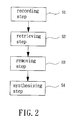
- FIG. 2 shows a flowchart of the EEG signal processing method of the preferred embodiment of the invention.
- FIG. 5 b shows EEG signal components after processing of an ICA operation.
- FIG. 5 c shows EEG signal components corrected by the EEG signal processing method of the invention.
- FIG. 6 a shows frequency response curves of an electrode Fp 1 .
- FIG. 6 c shows frequency response curves of an electrode Fp 2 .
- Couple means that two data processing units transfer data to each other via a data transfer interface for data transfer therebetween.
- the data processing units may be implemented by modular software, modular hardware or the combination thereof, as can be appreciated by one having ordinary skill in the art.
- separating matrix represents a matrix formed by independent signals separated from a received signal, as can be appreciated by one having ordinary skill in the art.
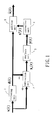
- the system includes a filtering unit 1 , a subtraction unit 2 , an analysis unit 3 , a correction unit 4 and an addition unit 5 .
- the filtering unit 1 filters an input signal x(k) detected by a plurality of electrodes (not shown) to obtain a predetermined frequency band signal d(k).
- the subtraction unit 2 is coupled to the filtering unit 1 and performs a subtraction operation between the input signal x(k) and the predetermined frequency band signal d (k) to obtain a difference signal x d (k).
- the analysis unit 3 is coupled to the subtraction unit 2 and performs an independent component analysis (ICA) on the predetermined frequency band signal d(k) to obtain an analysis signal y(k).
- the correction unit 4 is coupled to the analysis unit 3 and corrects the analysis signal y(k) in order to remove interfering signals from the EEG signal components. Thus, a corrected signal x′(k) is generated by the correction unit 4 .
- the addition unit 5 is coupled to the correction unit 4 and the filtering unit 1 and performs an addition operation between the corrected signal x′(k) and the predetermined frequency band signal d(k), thereby generating an output signal ⁇ circumflex over (x) ⁇ (k).
- the filtering unit 1 , the subtraction unit 2 , the analysis unit 3 , the correction unit 4 and the addition unit 5 can be implemented by the modular software, the modular hardware or the combination thereof, as can be appreciated by one having ordinary skill in the art.
- the filtering unit 1 , the subtraction unit 2 , the analysis unit 3 , the correction unit 4 and the addition unit 5 are implemented in term of the modular software by a device installed with a processing program and having numerical computation function and storage function (such as a computer or a digital signal processor (DSP)), but is not limited thereto.
- the flowchart includes a recording step S 1 , a retrieving step S 2 , a removing step S 3 and a synthesizing step S 4 .
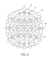
- the recording step S 1 obtains EEG signal components of a testee via a plurality of electrodes, with the EEG signal components serving as the input signal x(k). In this embodiment, there are m electrodes. Referring to FIG. 3 also, the electrodes are shown to cover all over a scalp Q of the testee. In this case, the recording step S 1 obtains the EEG signal components from the scalp Q of the testee via the plurality of electrodes E.
- the EEG signal components are obtained from a frontal site Qa, a temporal site Qb and a rear site Qc of the scalp Q of the testee via the electrodes Fp 1 , Fpz, Fp 2 , F 7 , F 3 , Fz, F 4 , F 8 (for the frontal site Qa), C 3 , Cz, C 4 , T 3 , T 4 (for the temporal site Qb), T 5 , T 6 , P 3 , Pz, P 4 , O 1 , Oz and O 2 (for the rear site Qc).
- the obtained EEG signal components are preferably magnified, sampled and quantified to form the input signal x(k), which is expressed by the formula below:
- k is discrete time
- m is the quantity of the electrodes
- [x 1 (k), . . . , x m (k)] are EEG signal components obtained by the in electrodes
- [x 1 (k), . . . , x m (k)] T is a transpose matrix of the signal matrix [x 1 (k), . . . , x m (k)].
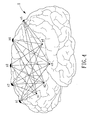
- FIG. 4 shows origins of EEG signal components. Since original EEG signal components s 1 , s 2 , s 3 and s 4 retrieved from the human brain H are easily contaminated by eye movement, blink, muscle movement, EKG or power line noises (not shown), the EEG signal components x 1 , x 2 , x 3 , x 4 and x 5 retrieved by the electrodes may be represented in terms of a signal gain A and an interference factor v(k) after magnification, as shown in formula (2) and (3) below:
- A is a matrix of signal gain
- s(k) is a matrix of original EEG signal components.
- n is 4
- s 1 , s 2 , s 3 and s 4 are original EEG signal components retrieved from various parts of the human brain H
- v(k) is a unknown vector representing errors or noises.
- the retrieving step S 2 filters the input signal x(k) to obtain the predetermined frequency band signal d(k) via the filtering unit 1 .
- the subtraction unit 2 subtracts the predetermined frequency band signal d(k) from the input signal x(k) to obtain the difference signal x d (k) for the following removing step S 3 .
- the filtering unit 1 is implemented as a conventional band pass filter (BPF) by the processing program, but is not limited thereto.
- the retrieving step S 2 filters the input signal x(k) to obtain the predetermined frequency band signal d(k) from the input signal x(k) via the filtering unit 1 for further storage.
- a Fourier transform is performed on the input signal x(k) to convert the input signal x(k) into frequency domain.
- Predetermined frequency band signals are retrieved from the input signal x(k) under frequency domain and then converted into time domain signal as the predetermined frequency band signal d(k).
- a waveforms of human brain are used as the predetermined frequency band signal d(k) for illustration purpose without taking it as a limited sense.
- the subtraction unit 2 subtracts the predetermined frequency band signal d(k) from the input signal x(k) to obtain the difference signal x d (k). The calculation of the subtraction unit 2 is expressed below:
- the removing step S 3 performs an ICA operation between the difference signal x d (k) and a separating matrix W to obtain the analysis signal y(k). Then, the correction unit 4 generates a separating pseudo inverse (W) + and an independent analysis signal y′(k) according to the separating matrix W and the analysis signal y(k) respectively, and performs a matrix operation between the separating pseudo inverse (W) + and the independent analysis signal y′(k) to obtain the corrected signal x′(k) for the following synthesizing step S 4 . Specifically, the removing step S 3 performs the blind source separation of the ICA algorithm based on the difference signal x d (k) and the separating matrix w via the analysis unit 3 . Namely, the removing step S 3 performs an ICA operation to obtain the analysis signal y(k), as can be appreciated by one having ordinary skill in this art.
- the analysis signal y(k) can be obtained according to the following formula:
- the correction unit 4 performs a Moore-Penrose pseudoinverse operation on the separating matrix W to obtain the separating pseudo inverse (W) + , and generates the independent analysis signal y′(k) based on independent waveforms of the analysis signal y(k).
- the rows of the independent analysis signal y′(k) representing interfering signals are set to zero, and a matrix operation is performed between the separating pseudo inverse (W) + and the independent analysis signal y′(k) to obtain the corrected signal x′(k).
- the corrected signal x′(k) can be obtained according to the following formula:
- the synthesizing step S 4 adds the corrected signal x′(k) and the predetermined frequency band signal d(k) together to obtain the output signal ⁇ circumflex over (x) ⁇ (k) via the addition unit 5 .
- the output signal ⁇ circumflex over (x) ⁇ (k) can be obtained according to the following formula:
- the output signal ⁇ circumflex over (x) ⁇ (k) can completely preserve the predetermined frequency band signal d(k) (while the conventional EEG signal processing method cannot do so) because the predetermined frequency band signal d(k) was obtained prior to the ICA algorithm operation and is added back to the corrected signal x′(k). Therefore, the invention can overcome the drawback of the convention EEG signal processing method where useful information contained in EEG signal components is lost after removal of interfering signals.
- FIG. 3 a top view of a human head covered with the electrodes is shown.
- Various artifact sources that cause interfering signals are separately described below.
- FIG. 5 a shows EEG signal components contaminated by an ocular artifact source.
- FIG. 5 b shows EEG signal components after being processed by the ICA operation (namely, the resulted EEG signal components of conventional ICA-based EEG signal processing methods).
- FIG. 5 c shows EEG signal components corrected by the EEG signal processing method of the invention.
- the EEG signal components contaminated by the ocular artifact source (as shown in FIG. 5 a ) are separated as an ICA component 1 shown in FIG. 5 b .
- After correction of the proposed EEG signal processing method it can be known from the EEG signal components (shown in FIG. 5 c ) detected by the electrodes E (numbered as Fp 1 , Fpz and Fp 2 ) that the ⁇ waveforms near 10 Hz are masked by the ocular artifact source.
- FIGS. 5 a , 5 b and 5 c it can be known from the EEG signal components (shown in FIG. 5 a ) detected by the electrodes E (numbered as T 5 and T 6 ) that the interfering signals caused by the muscle movement exist between 0 th to 2 nd second and is separated as ICA components 15 and 16 shown in FIG. 5 b . If the interfering signals are removed from certain rows of the independent analysis signal y′(k) in the removing step S 3 , it can be known from the FIGS. 5 a and 5 c that the signals of underlying EEG activities are obscured by the interfering signals of the rows caused by muscle movement.
- FIGS. 5 a , 5 b and 5 c it can be known from the FIG. 5 a that the interfering signals caused by the EKG appear in the EEG signal components detected by the electrode E (numbered as P 3 ).
- the EEG signal components contaminated by the EKG artifact source are separated as an ICA component 2 . If the interfering signals caused by EKG are removed from certain rows of the independent analysis signal y′(k) in the removing step S 3 , the EEG signal components detected by the electrode E (numbered as P 3 ) as shown in FIG. 5 c may depict signals of underlying EEG activities after correction.
- the power line noise artifact source may be categorized into two categories.
- the first category of the power line noise artifact source the contaminated EEG signal components (as shown in FIG. 5 a ) detected by the electrodes E (numbered as F 3 and P 4 ) are separated as ICA components 18 and 19 shown in FIG. 5 b .
- the second category of the power line noise artifact source the contaminated EEG signal components (as shown in FIG. 5 a ) detected by the electrode E (numbered as Pz) are separated as an ICA component 14 shown in FIG. 5 b.
- the level of relaxation of the testee can be determined based on whether the brain generates ⁇ waveforms or not.
- an example is made to illustrate that the EEG signal processing method of the invention is capable of processing ⁇ waveforms.
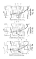
- FIGS. 6 a , 6 b and 6 c show frequency response diagrams of the electrodes Fp 1 , Fpz and Fp 2 , respectively.
- L 1 represents a curve of power spectral density (PSD) of contaminated EEG signal components
- L 2 represents a PSD curve of EEG signal components produced by conventional ICA-based EEG signal processing method
- L 3 represents a PSD curve of EEG signal components produced by the proposed EEG signal processing method. It can be known from the FIGS.
- the EEG signal processing method of the invention can efficiently preserve the a waveforms after removal of the interfering signals caused by artifact sources, as opposed to the conventional EEG signal processing method that causes the loss of a waveforms after removal of interfering signals.
- the EEG signal processing method of the invention is characterized as follows. First, the invention records EEG signal components of a testee as the input signal x(k) via the recording step S 1 . Second, the retrieving step S 2 filters the input signal x(k) to obtain the predetermined frequency band signal d(k), and subtracts the predetermined frequency band signal d(k) from the input signal x(k) to obtain the difference signal x d (k).
- the removing step S 3 performs an ICA operation between the predetermined frequency band signal d(k) and the separating matrix W to obtain the analysis signal y(k), generates the separating pseudo inverse (W) + and the independent analysis signal y′(k) based on the separating matrix W and the analysis signal y(k) respectively, and performs a matrix operation between the separating pseudo inverse (W) + and the independent analysis signal y′(k) to obtain the corrected signal x′(k).
- the synthesizing step S 4 adds the corrected signal x′(k) and the predetermined frequency band signal d(k) together to obtain the output signal ⁇ circumflex over (x) ⁇ (k).
- the output signal ⁇ circumflex over (x) ⁇ (k) can be obtained by adding corrected signal x′(k) and the predetermined frequency band signal d(k) together.
- the output signal ⁇ circumflex over (x) ⁇ (k) of the EEG signal processing method of the invention still contains the predetermined frequency band signal d(k), achieving preservation of useful frequency band signals required for certain brainwave analyses after removal of interfering signals.
- the invention achieves advantage of preserving required frequency band signals for various applications such as clinical diagnosis, distracted brainwave measurement, etc.
Landscapes
- Health & Medical Sciences (AREA)
- Life Sciences & Earth Sciences (AREA)
- Engineering & Computer Science (AREA)
- Medical Informatics (AREA)
- Surgery (AREA)
- Biophysics (AREA)
- Pathology (AREA)
- Signal Processing (AREA)
- Biomedical Technology (AREA)
- Heart & Thoracic Surgery (AREA)
- Psychiatry (AREA)
- Molecular Biology (AREA)
- Physics & Mathematics (AREA)
- Animal Behavior & Ethology (AREA)
- General Health & Medical Sciences (AREA)
- Public Health (AREA)
- Veterinary Medicine (AREA)
- Artificial Intelligence (AREA)
- Computer Vision & Pattern Recognition (AREA)
- Physiology (AREA)
- Psychology (AREA)
- Measurement And Recording Of Electrical Phenomena And Electrical Characteristics Of The Living Body (AREA)
Abstract
Description
- 1. Field of the Invention
- The present invention generally relates to an electroencephalogram signal processing method and, more particularly, to an EEG signal processing method that preserves predetermined frequency band signals before removing interfering signals thereof.
- 2. Description of the Related Art
- Electroencephalogram (EEG) data is a curved diagram formed by weak biological signals of a human brain, and is used to diagnose cerebrovascular diseases or epilepsy. However, EEG signals tend to be distorted under interferences caused by artifact sources. As an example, EEG signals are seriously interfered by eye movement, blink, muscle movement, electrocardiogram (EKG), power line noises, etc, leading to contamination of the EEG signals. In light of this, it is required to remove the interfering signals from the EEG signals before the EEG signals can be applied to medical diagnosis or brain status detection.
- Conventionally, contaminated EEG signals are visually checked to find out interfering signals contained therein, and the interfering signals are removed from the EEG signals to complete the EEG signal processing method. Alternatively, U.S. Pat. No. 5,513,649 entitled “ADAPTIVE INTERFERENCE CANCELER FOR EEG MOVEMENT AND EYE ARTIFACTS” discloses a sensor that can detect and remove the interfering signals, which are caused by artifact sources, from EEG signals. The EEG signals without interfering signals are output as an output signal. Finally, a feedback operation is performed on the output signal to obtain needed EEG signals. However, when the EEG signals are in a small amount or seriously interfered by muscle movement or power line noises, removing the interfering signals from the contaminated EEG signals may lead to a loss of some useful information, making the processed EEG signals not useful for clinical diagnosis.
- To solve the problem, other EEG signal processing methods were proposed to remove interfering signals from EEG signals based on Independent Component Analysis (ICA) algorithm. The ICA-based EEG signal processing methods can be seen in an IEEE paper entitled “Waveform-preserving blind estimation of multiple independent sources” or in a Taiwan patent with publication No. 201102047. In the Taiwan patent, independent components are retrieved from EEG data for blind signal separation (BSS). Namely, the independent components are retrieved for an ICA operation. Specifically, different interfering signals contained in the contaminated EEG data are separated as different ICA components. After the ICA components of the interfering signals are removed, other ICA components may construct a corrected EEG data, thereby removing the interfering signals from the EEG signals. However, since the signal sources in human brain are dependent from each other, the
- ICA components associated with interfering signals usually contain some frequency band signals required for certain EEG analysis, such as a waveforms (alpha rhythm) generated when human brain relaxes. As a result, the EEG data is not useful for clinical diagnosis.
- In light of the above problems, it is desired to provide an EEG signal processing method capable of preserving the frequency band signals required for EEG analyses after removal of the interfering signals.
- It is therefore the primary objective of this invention to provide an EEG signal processing method that preserves required predetermined frequency band signals before removing interfering signals thereof.
- The invention discloses an electroencephalogram signal processing method comprising a recording step, a retrieving step, a removing step and a synthesizing step. The recording step retrieves EEG signal components of a testee via a plurality of electrodes, wherein the EEG signal components serve as an input signal. The retrieving step filters the input signal to obtain a predetermined frequency band signal via a filtering unit, and subtracts the predetermined frequency band signal from the input signal to obtain a difference signal via a subtraction unit. The removing step performs an independent component analysis operation between the difference signal and a separating matrix to obtain an analysis signal via an analysis unit, generates a separating pseudo inverse and an independent analysis signal according to the separating matrix and the analysis signal respectively via a correction unit, and performs a matrix operation between the separating pseudo inverse and the independent analysis signal to obtain a corrected signal. The synthesizing step adds the corrected signal and the predetermined frequency band signal together to obtain an output signal via an addition unit.
- The present invention will become more fully understood from the detailed description given hereinafter and the accompanying drawings which are given by way of illustration only, and thus are not limitative of the present invention, and wherein:
-
FIG. 1 shows a system performing an EEG signal processing method according to a preferred embodiment of the invention. -
FIG. 2 shows a flowchart of the EEG signal processing method of the preferred embodiment of the invention. -
FIG. 3 is a top view of a human head covered with a plurality of electrodes. -
FIG. 4 shows original EEG signal components at various parts of a human brain. -
FIG. 5 a shows EEG signal components contaminated by artifact sources. -
FIG. 5 b shows EEG signal components after processing of an ICA operation. -
FIG. 5 c shows EEG signal components corrected by the EEG signal processing method of the invention. -
FIG. 6 a shows frequency response curves of an electrode Fp1. -
FIG. 6 b shows frequency response curves of an electrode Fpz. -
FIG. 6 c shows frequency response curves of an electrode Fp2. - In the various figures of the drawings, the same numerals designate the same or similar parts. Furthermore, when the term “first”, “second”, “third”, “fourth”, “inner”, “outer” “top”, “bottom” and similar terms are used hereinafter, it should be understood that these terms refer only to the structure shown in the drawings as it would appear to a person viewing the drawings, and are utilized only to facilitate describing the invention.
- The term “couple” referred hereinafter means that two data processing units transfer data to each other via a data transfer interface for data transfer therebetween. The data processing units may be implemented by modular software, modular hardware or the combination thereof, as can be appreciated by one having ordinary skill in the art.
- The term “separating matrix” referred hereinafter represents a matrix formed by independent signals separated from a received signal, as can be appreciated by one having ordinary skill in the art.
- Referring to
FIG. 1 , a system performing an EEG signal processing method is shown according to a preferred embodiment of the invention. The system includes afiltering unit 1, asubtraction unit 2, ananalysis unit 3, acorrection unit 4 and anaddition unit 5. Thefiltering unit 1 filters an input signal x(k) detected by a plurality of electrodes (not shown) to obtain a predetermined frequency band signal d(k). Thesubtraction unit 2 is coupled to thefiltering unit 1 and performs a subtraction operation between the input signal x(k) and the predetermined frequency band signal d (k) to obtain a difference signal xd(k). Theanalysis unit 3 is coupled to thesubtraction unit 2 and performs an independent component analysis (ICA) on the predetermined frequency band signal d(k) to obtain an analysis signal y(k). Thecorrection unit 4 is coupled to theanalysis unit 3 and corrects the analysis signal y(k) in order to remove interfering signals from the EEG signal components. Thus, a corrected signal x′(k) is generated by thecorrection unit 4. Theaddition unit 5 is coupled to thecorrection unit 4 and thefiltering unit 1 and performs an addition operation between the corrected signal x′(k) and the predetermined frequency band signal d(k), thereby generating an output signal {circumflex over (x)}(k). Thefiltering unit 1, thesubtraction unit 2, theanalysis unit 3, thecorrection unit 4 and theaddition unit 5 can be implemented by the modular software, the modular hardware or the combination thereof, as can be appreciated by one having ordinary skill in the art. In this embodiment, thefiltering unit 1, thesubtraction unit 2, theanalysis unit 3, thecorrection unit 4 and theaddition unit 5 are implemented in term of the modular software by a device installed with a processing program and having numerical computation function and storage function (such as a computer or a digital signal processor (DSP)), but is not limited thereto. - Referring to
FIGS. 1 and 2 , a flowchart of the EEG signal processing method is shown. The flowchart includes a recording step S1, a retrieving step S2, a removing step S3 and a synthesizing step S4. The recording step S1 obtains EEG signal components of a testee via a plurality of electrodes, with the EEG signal components serving as the input signal x(k). In this embodiment, there are m electrodes. Referring toFIG. 3 also, the electrodes are shown to cover all over a scalp Q of the testee. In this case, the recording step S1 obtains the EEG signal components from the scalp Q of the testee via the plurality of electrodes E. Specifically, the EEG signal components are obtained from a frontal site Qa, a temporal site Qb and a rear site Qc of the scalp Q of the testee via the electrodes Fp1, Fpz, Fp2, F7, F3, Fz, F4, F8 (for the frontal site Qa), C3, Cz, C4, T3, T4 (for the temporal site Qb), T5, T6, P3, Pz, P4, O1, Oz and O2 (for the rear site Qc). The obtained EEG signal components are preferably magnified, sampled and quantified to form the input signal x(k), which is expressed by the formula below: -
x(k)=[x 1(k), . . . x m(k)]T (1), - wherein k is discrete time, m is the quantity of the electrodes, [x1(k), . . . , xm(k)] are EEG signal components obtained by the in electrodes, and [x1(k), . . . , xm(k)]T is a transpose matrix of the signal matrix [x1(k), . . . , xm(k)].
-
FIG. 4 shows origins of EEG signal components. Since original EEG signal components s1, s2, s3 and s4 retrieved from the human brain H are easily contaminated by eye movement, blink, muscle movement, EKG or power line noises (not shown), the EEG signal components x1, x2, x3, x4 and x5 retrieved by the electrodes may be represented in terms of a signal gain A and an interference factor v(k) after magnification, as shown in formula (2) and (3) below: -
x(k)=As(k)+v(k) (2), -
s(k)=[s 1(k), . . . , S n(k)]T (3), - wherein A is a matrix of signal gain, and s(k) is a matrix of original EEG signal components. In this embodiment, n is 4, s1, s2, s3 and s4 are original EEG signal components retrieved from various parts of the human brain H, and v(k) is a unknown vector representing errors or noises.
- The retrieving step S2 filters the input signal x(k) to obtain the predetermined frequency band signal d(k) via the
filtering unit 1. Next, thesubtraction unit 2 subtracts the predetermined frequency band signal d(k) from the input signal x(k) to obtain the difference signal xd(k) for the following removing step S3. In the embodiment, thefiltering unit 1 is implemented as a conventional band pass filter (BPF) by the processing program, but is not limited thereto. Specifically, the retrieving step S2 filters the input signal x(k) to obtain the predetermined frequency band signal d(k) from the input signal x(k) via thefiltering unit 1 for further storage. For example, a Fourier transform is performed on the input signal x(k) to convert the input signal x(k) into frequency domain. Predetermined frequency band signals are retrieved from the input signal x(k) under frequency domain and then converted into time domain signal as the predetermined frequency band signal d(k). In this embodiment, a waveforms of human brain are used as the predetermined frequency band signal d(k) for illustration purpose without taking it as a limited sense. In the following, thesubtraction unit 2 subtracts the predetermined frequency band signal d(k) from the input signal x(k) to obtain the difference signal xd(k). The calculation of thesubtraction unit 2 is expressed below: -
x d(k)=x(k)−d(k) (4), - wherein k is discrete time.
- The removing step S3 performs an ICA operation between the difference signal xd(k) and a separating matrix W to obtain the analysis signal y(k). Then, the
correction unit 4 generates a separating pseudo inverse (W)+ and an independent analysis signal y′(k) according to the separating matrix W and the analysis signal y(k) respectively, and performs a matrix operation between the separating pseudo inverse (W)+ and the independent analysis signal y′(k) to obtain the corrected signal x′(k) for the following synthesizing step S4. Specifically, the removing step S3 performs the blind source separation of the ICA algorithm based on the difference signal xd(k) and the separating matrix w via theanalysis unit 3. Namely, the removing step S3 performs an ICA operation to obtain the analysis signal y(k), as can be appreciated by one having ordinary skill in this art. The analysis signal y(k) can be obtained according to the following formula: -
y(k)=Wx d(k) (5), - wherein k is discrete time. Next, the
correction unit 4 performs a Moore-Penrose pseudoinverse operation on the separating matrix W to obtain the separating pseudo inverse (W)+, and generates the independent analysis signal y′(k) based on independent waveforms of the analysis signal y(k). The rows of the independent analysis signal y′(k) representing interfering signals are set to zero, and a matrix operation is performed between the separating pseudo inverse (W)+ and the independent analysis signal y′(k) to obtain the corrected signal x′(k). The corrected signal x′(k) can be obtained according to the following formula: -
x′(k)=(W)+ y′(k) (6), - wherein k is discrete time.
- The synthesizing step S4 adds the corrected signal x′(k) and the predetermined frequency band signal d(k) together to obtain the output signal {circumflex over (x)}(k) via the
addition unit 5. The output signal {circumflex over (x)}(k) can be obtained according to the following formula: -
{circumflex over (x)}(k)=x′(k)+d(k) (7). - In the above formula (7), although the corrected signal x′(k) losses some useful information when the ICA algorithm operation is performed on the corrected signal x′(k) to remove interfering signals, the output signal {circumflex over (x)}(k) can completely preserve the predetermined frequency band signal d(k) (while the conventional EEG signal processing method cannot do so) because the predetermined frequency band signal d(k) was obtained prior to the ICA algorithm operation and is added back to the corrected signal x′(k). Therefore, the invention can overcome the drawback of the convention EEG signal processing method where useful information contained in EEG signal components is lost after removal of interfering signals.
- The improvement of the proposed EEG signal processing method applied to remove the interfering signals caused by ocular movement, muscle movement, EKG or line noises is described later in the specification. As shown in
FIG. 3 , a top view of a human head covered with the electrodes is shown. Various artifact sources that cause interfering signals are separately described below. - (A) Ocular artifact source:
-
FIG. 5 a shows EEG signal components contaminated by an ocular artifact source.FIG. 5 b shows EEG signal components after being processed by the ICA operation (namely, the resulted EEG signal components of conventional ICA-based EEG signal processing methods).FIG. 5 c shows EEG signal components corrected by the EEG signal processing method of the invention. The EEG signal components contaminated by the ocular artifact source (as shown inFIG. 5 a) are separated as anICA component 1 shown inFIG. 5 b. After correction of the proposed EEG signal processing method, it can be known from the EEG signal components (shown inFIG. 5 c) detected by the electrodes E (numbered as Fp1, Fpz and Fp2) that the α waveforms near 10 Hz are masked by the ocular artifact source. - (B) Muscle artifact source:
- Please refer to
FIGS. 5 a, 5 b and 5 c again, it can be known from the EEG signal components (shown inFIG. 5 a) detected by the electrodes E (numbered as T5 and T6) that the interfering signals caused by the muscle movement exist between 0th to 2nd second and is separated asICA components FIG. 5 b. If the interfering signals are removed from certain rows of the independent analysis signal y′(k) in the removing step S3, it can be known from theFIGS. 5 a and 5 c that the signals of underlying EEG activities are obscured by the interfering signals of the rows caused by muscle movement. - (C) EKG artifact source:
- Please refer to
FIGS. 5 a, 5 b and 5 c again, it can be known from theFIG. 5 a that the interfering signals caused by the EKG appear in the EEG signal components detected by the electrode E (numbered as P3). The EEG signal components contaminated by the EKG artifact source (as shown inFIG. 5 a) are separated as anICA component 2. If the interfering signals caused by EKG are removed from certain rows of the independent analysis signal y′(k) in the removing step S3, the EEG signal components detected by the electrode E (numbered as P3) as shown inFIG. 5 c may depict signals of underlying EEG activities after correction. - (D) Power line noise artifact source:
- Please refer to
FIGS. 5 a, 5 b and 5 c again, it can be known from theFIG. 5 a that the power line noise artifact source may be categorized into two categories. In the first category of the power line noise artifact source, the contaminated EEG signal components (as shown inFIG. 5 a) detected by the electrodes E (numbered as F3 and P4) are separated asICA components 18 and 19 shown inFIG. 5 b. In the second category of the power line noise artifact source, the contaminated EEG signal components (as shown inFIG. 5 a) detected by the electrode E (numbered as Pz) are separated as anICA component 14 shown inFIG. 5 b. - Moreover, because human brain generates a waveforms when human body is in relaxation, the level of relaxation of the testee can be determined based on whether the brain generates α waveforms or not. In the following, an example is made to illustrate that the EEG signal processing method of the invention is capable of processing α waveforms.
-
FIGS. 6 a, 6 b and 6 c show frequency response diagrams of the electrodes Fp1, Fpz and Fp2, respectively. In theFIGS. 6 a, 6 b and 6 c, L1 represents a curve of power spectral density (PSD) of contaminated EEG signal components, L2 represents a PSD curve of EEG signal components produced by conventional ICA-based EEG signal processing method, and L3 represents a PSD curve of EEG signal components produced by the proposed EEG signal processing method. It can be known from theFIGS. 6 a, 6 b and 6 c that the EEG signal components corrected by the EEG signal processing method of the invention do not contain interfering signals caused by the ocular artifact source while preserving useful α waveforms (8 Hz to 13 Hz). In other words, the EEG signal processing method of the invention can efficiently preserve the a waveforms after removal of the interfering signals caused by artifact sources, as opposed to the conventional EEG signal processing method that causes the loss of a waveforms after removal of interfering signals. - Based on the above technical features, the EEG signal processing method of the invention is characterized as follows. First, the invention records EEG signal components of a testee as the input signal x(k) via the recording step S1. Second, the retrieving step S2 filters the input signal x(k) to obtain the predetermined frequency band signal d(k), and subtracts the predetermined frequency band signal d(k) from the input signal x(k) to obtain the difference signal xd(k). Third, the removing step S3 performs an ICA operation between the predetermined frequency band signal d(k) and the separating matrix W to obtain the analysis signal y(k), generates the separating pseudo inverse (W)+ and the independent analysis signal y′(k) based on the separating matrix W and the analysis signal y(k) respectively, and performs a matrix operation between the separating pseudo inverse (W)+ and the independent analysis signal y′(k) to obtain the corrected signal x′(k). Finally, the synthesizing step S4 adds the corrected signal x′(k) and the predetermined frequency band signal d(k) together to obtain the output signal {circumflex over (x)}(k). Since the predetermined frequency band signal d(k) was obtained prior to the ICA algorithm operation, the output signal {circumflex over (x)}(k) can be obtained by adding corrected signal x′(k) and the predetermined frequency band signal d(k) together.
- Therefore, the output signal {circumflex over (x)}(k) of the EEG signal processing method of the invention still contains the predetermined frequency band signal d(k), achieving preservation of useful frequency band signals required for certain brainwave analyses after removal of interfering signals. Thus, the invention achieves advantage of preserving required frequency band signals for various applications such as clinical diagnosis, distracted brainwave measurement, etc.
- Although the invention has been described in detail with reference to its presently preferable embodiment, it will be understood by one of ordinary skill in the art that various modifications can be made without departing from the spirit and the scope of the invention, as set forth in the appended claims.
Claims (6)
Applications Claiming Priority (2)
| Application Number | Priority Date | Filing Date | Title |
|---|---|---|---|
| TW201102047 | 2011-01-16 | ||
| TW201102047 | 2011-01-16 |
Publications (2)
| Publication Number | Publication Date |
|---|---|
| US20120184869A1 true US20120184869A1 (en) | 2012-07-19 |
| US8670821B2 US8670821B2 (en) | 2014-03-11 |
Family
ID=46491299
Family Applications (1)
| Application Number | Title | Priority Date | Filing Date |
|---|---|---|---|
| US13/285,736 Expired - Fee Related US8670821B2 (en) | 2011-01-16 | 2011-10-31 | Electroencephalogram signal processing method |
Country Status (1)
| Country | Link |
|---|---|
| US (1) | US8670821B2 (en) |
Cited By (3)
| Publication number | Priority date | Publication date | Assignee | Title |
|---|---|---|---|---|
| FR3010891A1 (en) * | 2013-09-26 | 2015-03-27 | Commissariat Energie Atomique | METHOD, SYSTEM AND COMPUTER PROGRAM FOR DETECTION AND CHARACTERIZATION OF OCULAR BLINKING BY ELECTRO-ENCEPHALOGRAPHY |
| US20160242690A1 (en) * | 2013-12-17 | 2016-08-25 | University Of Florida Research Foundation, Inc. | Brain state advisory system using calibrated metrics and optimal time-series decomposition |
| CN119970034A (en) * | 2024-12-31 | 2025-05-13 | 武汉纺织大学 | Sentiment monitoring method based on online independent component analysis |
Citations (3)
| Publication number | Priority date | Publication date | Assignee | Title |
|---|---|---|---|---|
| US6073040A (en) * | 1997-01-20 | 2000-06-06 | Nec Corporation | Electrophysiological activity estimation method |
| US7630757B2 (en) * | 1997-01-06 | 2009-12-08 | Flint Hills Scientific Llc | System for the prediction, rapid detection, warning, prevention, or control of changes in activity states in the brain of a subject |
| US20130060125A1 (en) * | 2010-04-16 | 2013-03-07 | Applied Brain And Vision Sciences Inc. | Encephalography method and apparatus incorporating independent component analysis and a spectral shaping filter |
Family Cites Families (1)
| Publication number | Priority date | Publication date | Assignee | Title |
|---|---|---|---|---|
| TW201102047A (en) | 2009-07-14 | 2011-01-16 | Univ Nat Chiao Tung | Distraction brain wave measuring analytical method and the application system thereof |
-
2011
- 2011-10-31 US US13/285,736 patent/US8670821B2/en not_active Expired - Fee Related
Patent Citations (4)
| Publication number | Priority date | Publication date | Assignee | Title |
|---|---|---|---|---|
| US7630757B2 (en) * | 1997-01-06 | 2009-12-08 | Flint Hills Scientific Llc | System for the prediction, rapid detection, warning, prevention, or control of changes in activity states in the brain of a subject |
| US20100198098A1 (en) * | 1997-01-06 | 2010-08-05 | Ivan Osorio | System for the prediction, rapid detection, warning, prevention, or control of changes in activity states in the brain of a subject |
| US6073040A (en) * | 1997-01-20 | 2000-06-06 | Nec Corporation | Electrophysiological activity estimation method |
| US20130060125A1 (en) * | 2010-04-16 | 2013-03-07 | Applied Brain And Vision Sciences Inc. | Encephalography method and apparatus incorporating independent component analysis and a spectral shaping filter |
Cited By (5)
| Publication number | Priority date | Publication date | Assignee | Title |
|---|---|---|---|---|
| FR3010891A1 (en) * | 2013-09-26 | 2015-03-27 | Commissariat Energie Atomique | METHOD, SYSTEM AND COMPUTER PROGRAM FOR DETECTION AND CHARACTERIZATION OF OCULAR BLINKING BY ELECTRO-ENCEPHALOGRAPHY |
| WO2015044216A1 (en) * | 2013-09-26 | 2015-04-02 | Commissariat à l'énergie atomique et aux énergies alternatives | Method, system and computer program for detection and characterisation of ocular blinking by electroencephalography |
| US20160242690A1 (en) * | 2013-12-17 | 2016-08-25 | University Of Florida Research Foundation, Inc. | Brain state advisory system using calibrated metrics and optimal time-series decomposition |
| US10531806B2 (en) * | 2013-12-17 | 2020-01-14 | University Of Florida Research Foundation, Inc. | Brain state advisory system using calibrated metrics and optimal time-series decomposition |
| CN119970034A (en) * | 2024-12-31 | 2025-05-13 | 武汉纺织大学 | Sentiment monitoring method based on online independent component analysis |
Also Published As
| Publication number | Publication date |
|---|---|
| US8670821B2 (en) | 2014-03-11 |
Similar Documents
| Publication | Publication Date | Title |
|---|---|---|
| VISHWAKARMA et al. | An Effective Cascaded Approach for EEG Artifacts Elimination. | |
| Klug et al. | Zapline‐plus: A Zapline extension for automatic and adaptive removal of frequency‐specific noise artifacts in M/EEG | |
| Roy et al. | A NLMS based approach for artifacts removal in multichannel EEG signals with ICA and double density wavelet transform | |
| Sameni et al. | A nonlinear Bayesian filtering framework for ECG denoising | |
| Peng et al. | Removal of ocular artifacts in EEG—An improved approach combining DWT and ANC for portable applications | |
| US20090264786A1 (en) | System and Method For Signal Denoising Using Independent Component Analysis and Fractal Dimension Estimation | |
| Jafarifarmand et al. | Real-time ocular artifacts removal of EEG data using a hybrid ICA-ANC approach | |
| Sheela et al. | A hybrid method for artifact removal of visual evoked EEG | |
| Kasambe et al. | VLSI wavelet based denoising of PPG signal | |
| Kaczorowska et al. | Comparison of the ICA and PCA methods in correction of EEG signal artefacts | |
| JP5536739B2 (en) | EEG measurement method, EEG measurement apparatus, and recording medium | |
| CN110292376A (en) | Remove method, apparatus, equipment and the storage medium of eye electricity artefact in EEG signals | |
| US8670821B2 (en) | Electroencephalogram signal processing method | |
| Yadav et al. | Denoising and SNR improvement of ECG signals using wavelet based techniques | |
| Aiboud et al. | Review of ECG signal de-noising techniques | |
| KR101048763B1 (en) | Signal detection device and method | |
| Arpaia et al. | Low-density EEG correction with multivariate decomposition and subspace reconstruction | |
| Mateo et al. | Eye movement artefact suppression using Volterra filter for electroencephalography signals | |
| Yoon et al. | An automated motion artifact removal algorithm in electrocardiogram based on independent component analysis | |
| Massar et al. | Improvements of EEG Signal Quality: A Hybrid Method of Blind Source Separation and Variational Mode Destruction to Reduce Artifacts. | |
| Dhole et al. | A Review of EEG Artifact Removal Techniques for Brain-Computer Interface | |
| Mourad | Automatic correction of short‐duration artefacts in single‐channel EEG recording: a group‐sparse signal denoising algorithm | |
| Ferdous et al. | Sub-band selection approach to artifact suppression from electroencephalography signal using hybrid wavelet transform | |
| TWI433664B (en) | A signal processing method for electroencephalogram | |
| CN107174236B (en) | Electrocardiosignal denoising method and device based on optimization theory |
Legal Events
| Date | Code | Title | Description |
|---|---|---|---|
| AS | Assignment |
Owner name: I-SHOU UNIVERSITY, TAIWAN Free format text: ASSIGNMENT OF ASSIGNORS INTEREST;ASSIGNORS:CHIANG, CHING-TAI;WU, RONG-CHING;OUYANG, CHEN-SEN;AND OTHERS;REEL/FRAME:027150/0294 Effective date: 20110624 |
|
| STCF | Information on status: patent grant |
Free format text: PATENTED CASE |
|
| MAFP | Maintenance fee payment |
Free format text: PAYMENT OF MAINTENANCE FEE, 4TH YR, SMALL ENTITY (ORIGINAL EVENT CODE: M2551) Year of fee payment: 4 |
|
| FEPP | Fee payment procedure |
Free format text: MAINTENANCE FEE REMINDER MAILED (ORIGINAL EVENT CODE: REM.); ENTITY STATUS OF PATENT OWNER: SMALL ENTITY |
|
| LAPS | Lapse for failure to pay maintenance fees |
Free format text: PATENT EXPIRED FOR FAILURE TO PAY MAINTENANCE FEES (ORIGINAL EVENT CODE: EXP.); ENTITY STATUS OF PATENT OWNER: SMALL ENTITY |
|
| STCH | Information on status: patent discontinuation |
Free format text: PATENT EXPIRED DUE TO NONPAYMENT OF MAINTENANCE FEES UNDER 37 CFR 1.362 |
|
| FP | Lapsed due to failure to pay maintenance fee |
Effective date: 20220311 |