US20120184841A1 - Retrospective calculation of radiation dose and improved therapy planning - Google Patents
Retrospective calculation of radiation dose and improved therapy planning Download PDFInfo
- Publication number
- US20120184841A1 US20120184841A1 US13/496,208 US201013496208A US2012184841A1 US 20120184841 A1 US20120184841 A1 US 20120184841A1 US 201013496208 A US201013496208 A US 201013496208A US 2012184841 A1 US2012184841 A1 US 2012184841A1
- Authority
- US
- United States
- Prior art keywords
- radiation
- target volume
- treatment
- radiation dose
- target
- Prior art date
- Legal status (The legal status is an assumption and is not a legal conclusion. Google has not performed a legal analysis and makes no representation as to the accuracy of the status listed.)
- Granted
Links
- 230000005855 radiation Effects 0.000 title claims abstract description 194
- 238000002560 therapeutic procedure Methods 0.000 title description 10
- 238000011282 treatment Methods 0.000 claims abstract description 56
- 238000001959 radiotherapy Methods 0.000 claims abstract description 48
- 230000005291 magnetic effect Effects 0.000 claims abstract description 42
- 238000002203 pretreatment Methods 0.000 claims abstract description 31
- 238000000034 method Methods 0.000 claims description 24
- 238000001514 detection method Methods 0.000 claims description 16
- 238000003384 imaging method Methods 0.000 claims description 7
- 230000003068 static effect Effects 0.000 claims description 4
- 238000004590 computer program Methods 0.000 claims 1
- 210000001519 tissue Anatomy 0.000 description 13
- 206010028980 Neoplasm Diseases 0.000 description 5
- 238000002591 computed tomography Methods 0.000 description 4
- 210000000056 organ Anatomy 0.000 description 4
- 238000004611 spectroscopical analysis Methods 0.000 description 4
- 230000001225 therapeutic effect Effects 0.000 description 4
- 239000003795 chemical substances by application Substances 0.000 description 3
- 238000011461 current therapy Methods 0.000 description 3
- 238000005194 fractionation Methods 0.000 description 3
- WTFXARWRTYJXII-UHFFFAOYSA-N iron(2+);iron(3+);oxygen(2-) Chemical compound [O-2].[O-2].[O-2].[O-2].[Fe+2].[Fe+3].[Fe+3] WTFXARWRTYJXII-UHFFFAOYSA-N 0.000 description 3
- 238000002595 magnetic resonance imaging Methods 0.000 description 3
- 239000006096 absorbing agent Substances 0.000 description 2
- 230000004075 alteration Effects 0.000 description 2
- 230000008901 benefit Effects 0.000 description 2
- 230000000903 blocking effect Effects 0.000 description 2
- 230000002708 enhancing effect Effects 0.000 description 2
- 238000011156 evaluation Methods 0.000 description 2
- 210000004907 gland Anatomy 0.000 description 2
- 230000001678 irradiating effect Effects 0.000 description 2
- 239000011572 manganese Substances 0.000 description 2
- 238000012986 modification Methods 0.000 description 2
- 230000004048 modification Effects 0.000 description 2
- 238000012544 monitoring process Methods 0.000 description 2
- 239000002245 particle Substances 0.000 description 2
- 238000012545 processing Methods 0.000 description 2
- 230000000241 respiratory effect Effects 0.000 description 2
- 230000029058 respiratory gaseous exchange Effects 0.000 description 2
- 238000007493 shaping process Methods 0.000 description 2
- 229910052688 Gadolinium Inorganic materials 0.000 description 1
- PWHULOQIROXLJO-UHFFFAOYSA-N Manganese Chemical compound [Mn] PWHULOQIROXLJO-UHFFFAOYSA-N 0.000 description 1
- 238000010521 absorption reaction Methods 0.000 description 1
- 238000004458 analytical method Methods 0.000 description 1
- 238000013459 approach Methods 0.000 description 1
- 230000000712 assembly Effects 0.000 description 1
- 238000000429 assembly Methods 0.000 description 1
- 210000000988 bone and bone Anatomy 0.000 description 1
- 201000011510 cancer Diseases 0.000 description 1
- 230000007423 decrease Effects 0.000 description 1
- 238000003708 edge detection Methods 0.000 description 1
- 230000000694 effects Effects 0.000 description 1
- 230000005284 excitation Effects 0.000 description 1
- 239000003302 ferromagnetic material Substances 0.000 description 1
- 238000002594 fluoroscopy Methods 0.000 description 1
- 230000006870 function Effects 0.000 description 1
- UIWYJDYFSGRHKR-UHFFFAOYSA-N gadolinium atom Chemical compound [Gd] UIWYJDYFSGRHKR-UHFFFAOYSA-N 0.000 description 1
- 210000004072 lung Anatomy 0.000 description 1
- 229910052748 manganese Inorganic materials 0.000 description 1
- 238000011369 optimal treatment Methods 0.000 description 1
- 230000035790 physiological processes and functions Effects 0.000 description 1
- 230000008569 process Effects 0.000 description 1
- 230000000541 pulsatile effect Effects 0.000 description 1
- 230000008439 repair process Effects 0.000 description 1
- 230000011218 segmentation Effects 0.000 description 1
- 210000000278 spinal cord Anatomy 0.000 description 1
- 238000002604 ultrasonography Methods 0.000 description 1
- 230000004584 weight gain Effects 0.000 description 1
- 235000019786 weight gain Nutrition 0.000 description 1
- 230000004580 weight loss Effects 0.000 description 1
Images
Classifications
-
- A—HUMAN NECESSITIES
- A61—MEDICAL OR VETERINARY SCIENCE; HYGIENE
- A61N—ELECTROTHERAPY; MAGNETOTHERAPY; RADIATION THERAPY; ULTRASOUND THERAPY
- A61N5/00—Radiation therapy
- A61N5/10—X-ray therapy; Gamma-ray therapy; Particle-irradiation therapy
- A61N5/1048—Monitoring, verifying, controlling systems and methods
- A61N5/1071—Monitoring, verifying, controlling systems and methods for verifying the dose delivered by the treatment plan
-
- A—HUMAN NECESSITIES
- A61—MEDICAL OR VETERINARY SCIENCE; HYGIENE
- A61N—ELECTROTHERAPY; MAGNETOTHERAPY; RADIATION THERAPY; ULTRASOUND THERAPY
- A61N5/00—Radiation therapy
- A61N5/10—X-ray therapy; Gamma-ray therapy; Particle-irradiation therapy
- A61N5/103—Treatment planning systems
- A61N5/1031—Treatment planning systems using a specific method of dose optimization
-
- A—HUMAN NECESSITIES
- A61—MEDICAL OR VETERINARY SCIENCE; HYGIENE
- A61N—ELECTROTHERAPY; MAGNETOTHERAPY; RADIATION THERAPY; ULTRASOUND THERAPY
- A61N5/00—Radiation therapy
- A61N5/10—X-ray therapy; Gamma-ray therapy; Particle-irradiation therapy
- A61N5/103—Treatment planning systems
- A61N5/1039—Treatment planning systems using functional images, e.g. PET or MRI
-
- A—HUMAN NECESSITIES
- A61—MEDICAL OR VETERINARY SCIENCE; HYGIENE
- A61N—ELECTROTHERAPY; MAGNETOTHERAPY; RADIATION THERAPY; ULTRASOUND THERAPY
- A61N5/00—Radiation therapy
- A61N5/10—X-ray therapy; Gamma-ray therapy; Particle-irradiation therapy
- A61N5/1048—Monitoring, verifying, controlling systems and methods
- A61N5/1049—Monitoring, verifying, controlling systems and methods for verifying the position of the patient with respect to the radiation beam
-
- G—PHYSICS
- G01—MEASURING; TESTING
- G01R—MEASURING ELECTRIC VARIABLES; MEASURING MAGNETIC VARIABLES
- G01R33/00—Arrangements or instruments for measuring magnetic variables
- G01R33/20—Arrangements or instruments for measuring magnetic variables involving magnetic resonance
- G01R33/28—Details of apparatus provided for in groups G01R33/44 - G01R33/64
- G01R33/38—Systems for generation, homogenisation or stabilisation of the main or gradient magnetic field
- G01R33/381—Systems for generation, homogenisation or stabilisation of the main or gradient magnetic field using electromagnets
-
- G—PHYSICS
- G01—MEASURING; TESTING
- G01R—MEASURING ELECTRIC VARIABLES; MEASURING MAGNETIC VARIABLES
- G01R33/00—Arrangements or instruments for measuring magnetic variables
- G01R33/20—Arrangements or instruments for measuring magnetic variables involving magnetic resonance
- G01R33/44—Arrangements or instruments for measuring magnetic variables involving magnetic resonance using nuclear magnetic resonance [NMR]
- G01R33/48—NMR imaging systems
- G01R33/4808—Multimodal MR, e.g. MR combined with positron emission tomography [PET], MR combined with ultrasound or MR combined with computed tomography [CT]
-
- A—HUMAN NECESSITIES
- A61—MEDICAL OR VETERINARY SCIENCE; HYGIENE
- A61N—ELECTROTHERAPY; MAGNETOTHERAPY; RADIATION THERAPY; ULTRASOUND THERAPY
- A61N5/00—Radiation therapy
- A61N5/10—X-ray therapy; Gamma-ray therapy; Particle-irradiation therapy
- A61N5/1048—Monitoring, verifying, controlling systems and methods
- A61N5/1049—Monitoring, verifying, controlling systems and methods for verifying the position of the patient with respect to the radiation beam
- A61N2005/1055—Monitoring, verifying, controlling systems and methods for verifying the position of the patient with respect to the radiation beam using magnetic resonance imaging [MRI]
-
- A—HUMAN NECESSITIES
- A61—MEDICAL OR VETERINARY SCIENCE; HYGIENE
- A61N—ELECTROTHERAPY; MAGNETOTHERAPY; RADIATION THERAPY; ULTRASOUND THERAPY
- A61N5/00—Radiation therapy
- A61N5/10—X-ray therapy; Gamma-ray therapy; Particle-irradiation therapy
- A61N5/1048—Monitoring, verifying, controlling systems and methods
- A61N5/1049—Monitoring, verifying, controlling systems and methods for verifying the position of the patient with respect to the radiation beam
- A61N2005/1058—Monitoring, verifying, controlling systems and methods for verifying the position of the patient with respect to the radiation beam using ultrasound imaging
-
- G—PHYSICS
- G01—MEASURING; TESTING
- G01R—MEASURING ELECTRIC VARIABLES; MEASURING MAGNETIC VARIABLES
- G01R33/00—Arrangements or instruments for measuring magnetic variables
- G01R33/20—Arrangements or instruments for measuring magnetic variables involving magnetic resonance
- G01R33/28—Details of apparatus provided for in groups G01R33/44 - G01R33/64
- G01R33/38—Systems for generation, homogenisation or stabilisation of the main or gradient magnetic field
- G01R33/3806—Open magnet assemblies for improved access to the sample, e.g. C-type or U-type magnets
-
- G—PHYSICS
- G01—MEASURING; TESTING
- G01R—MEASURING ELECTRIC VARIABLES; MEASURING MAGNETIC VARIABLES
- G01R33/00—Arrangements or instruments for measuring magnetic variables
- G01R33/20—Arrangements or instruments for measuring magnetic variables involving magnetic resonance
- G01R33/44—Arrangements or instruments for measuring magnetic variables involving magnetic resonance using nuclear magnetic resonance [NMR]
- G01R33/48—NMR imaging systems
- G01R33/54—Signal processing systems, e.g. using pulse sequences ; Generation or control of pulse sequences; Operator console
- G01R33/56—Image enhancement or correction, e.g. subtraction or averaging techniques, e.g. improvement of signal-to-noise ratio and resolution
- G01R33/5601—Image enhancement or correction, e.g. subtraction or averaging techniques, e.g. improvement of signal-to-noise ratio and resolution involving use of a contrast agent for contrast manipulation, e.g. a paramagnetic, super-paramagnetic, ferromagnetic or hyperpolarised contrast agent
Definitions
- the present application relates to a method and system for improved planning and delivery of radiation therapy. It finds particular application to combined magnetic resonance imaging (MRI) and radiotherapy systems capable of simultaneous MR imaging and irradiation, but it may find application in other imaging or spectroscopy modalities or other types of treatment.
- MRI magnetic resonance imaging
- radiotherapy systems capable of simultaneous MR imaging and irradiation, but it may find application in other imaging or spectroscopy modalities or other types of treatment.
- Radiation therapy is a common therapeutic technique in oncology in which a dose of high energy gamma ( ⁇ ) radiation, particle beam, or other radiation is delivered to a patient's body to achieve a therapeutic effect, i.e. eradicate cancerous tissue.
- the dose is fractionated, or spread out over a period of several weeks, for several reasons.
- fractionation allows for the healthy tissue damaged during treatments to recover, without allowing the less efficient cancer tissue to repair between fractions.
- a therapy plan is generated prior to treatment which details the fractionation schedule along with optimal beam shape and direction.
- a static volumetric image e.g. a computed tomography (CT) image
- CT computed tomography
- a computerized planning system automatically or semi-automatically delineates contours of the target volume, healthy surrounding tissue, and sensitive areas at risk of being damaged, such as the spinal cord, glands, or the like, radiation blocking or attenuating tissue, such as bone, etc.
- the planning system uses the contour data, the planning system then determines an optimal treatment plan which details the radiation dose distribution and fractionation schedule along with radiation beam direction and shape.
- an image, e.g. fluoroscopic, x-ray, or the like, of the target volume is taken to align the target volumes position to the radiation therapy coordinate system and to verify the accuracy of the current therapy plan.
- the therapy plan can lose accuracy during the treatment process because of positioning accuracy, day-to-day variations in organ position, breathing, heartbeat, increases/decreases in tumor size, and other physiological processes, e.g. bladder filling or the like.
- current methods involve irradiating a volume slightly larger than the target volume determined from the static volumetric image. This approach leads to increased damage to healthy tissue and can lead to extraneous side effects. If the current therapy plan significantly changes, e.g. if the target volume size has shrunk due to treatment, it can be cancelled and a new therapy plan is generated which can be time-consuming
- the present application provides a new and improved MRI based image guided radiotherapy dose planning which overcomes the above-referenced problems and others.
- a method for radiation dose delivery includes generating a radiation therapy plan, the radiation therapy plan includes a plurality of radiation doses.
- a pre-treatment image representation of a target volume and non-target volumes is acquired and a contour and position of the target volume and at least one non-target volume is determined based on the pre-treatment image representation.
- a radiation dose including a plurality of radiation beam trajectories and at least one radiation beam geometry is administered.
- An actual radiation dose delivered to each region of the target volume and the at least one non-target volume is determined based on their determined contours and positions, the radiation beam trajectories and the at least one radiation beam geometry.
- a magnetic resonance guided radiotherapy device in accordance with another aspect, includes a bore-type magnet which generates a static magnetic field in an examination region, the magnet being configured with a magnet radiation translucent region which allows radiation beams to travel radially through the bore-type magnet into a subject disposed therein.
- a split-type gradient coil which defines a gap including a gradient coil radiation translucent region aligned to the magnet radiation translucent region, the split-type coil being configured to apply selected magnetic field gradient pulses across the imaging region.
- a radiofrequency (RF) coil is configured to induce and manipulate magnetic resonance in a subject in the examination region and/or acquire magnetic resonance data from the examination region.
- a radiation source disposed laterally to the bore-type magnet, the radiation source being positioned to transmit the radiation beams through the magnet and gradient coil radiation translucent regions to an isocenter of the bore-type magnet and a scanner controller which controls the gradient coil and RF coil to generate an image representation.
- One advantage relies in that radiation exposure to healthy tissue is reduced.
- the invention may take form in various components and arrangements of components, and in various steps and arrangements of steps.
- the drawings are only for purposes of illustrating the preferred embodiments and are not to be construed as limiting the invention.
- FIG. 1 is a diagrammatic illustration of a combined magnetic resonance (MR) and radiotherapy system
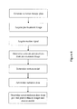
- FIG. 2 is a flow chart of a method for radiation treatment
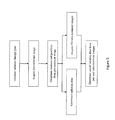
- FIG. 3 is a flow chart of another method for radiation dose delivery
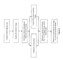
- FIG. 4 is a flow chart of another method for radiation dose delivery
- FIG. 5 is a flow chart of another method for radiation dose delivery.
- FIG. 6 is a flow chart of another method for radiation dose delivery.
- a combined magnetic resonance (MR) and radiotherapy system 10 includes a main magnet 12 which generates a temporally uniform B 0 field through an examination region 14 .
- the main magnet can be an annular or bore-type magnet, a C-shaped open magnet, other designs of open magnets, or the like.
- the magnet includes a magnet radiation translucent region 16 which allows a radiation beam, such as gamma ( ⁇ ) rays, x-rays, particle beams, or the like, to pass through the magnet.
- the main magnet 12 is a bore-type magnet.
- the magnet radiation translucent region 16 is arranged circumferentially to allow the radiation beam to travel radially through an isocenter of the bore.
- Gradient magnetic field coils 18 disposed adjacent the main magnet serve to generate magnetic field gradients along selected axes relative to the B 0 magnetic field for spatially encoding magnetic resonance signals, for producing magnetization-spoiling field gradients, or the like.
- the gradient magnetic field coils 18 include a gradient radiation translucent region 20 aligned to the magnet radiation translucent region 16 to allow the radiation beam to travel through the main magnet 12 and gradient magnetic field coils 18 in a predictable manner to a subject 22 in the examination region 14 , i.e. the absorption throughout the radiation translucent regions 16 , 20 is constant.
- the magnetic field gradient coil 18 may include coil segments configured to produce magnetic field gradients in three orthogonal directions, typically longitudinal or z, transverse or x, and vertical or y directions.
- the radiation beam originates from a radiation source 24 , such as a linear accelerator or the like, disposed laterally to the main magnet 12 and adjacent to the radiation translucent regions 16 , 20 .
- An absorber 26 absorbs any radiation from the source 24 travelling in an unwanted direction.
- a collimator 28 helps shaping the beam of radiation to localize the treatment to a target volume 30 .
- the collimator is an adjustable collimator, such as a multi-leaf collimator (MLC) or the like, which modulates the radiation beam geometry.
- MLC multi-leaf collimator
- the leaves of the MLC allow for conformal shaping of the radiation beam to match the shape of the target volume 30 from each angular position of the radiation beam around the subject.
- a radiation source assembly 32 composed of the radiation source 24 , the absorber 26 , and the collimator 28 , is mounted on a rail system 34 which allows the radiation source assembly to be rotated circumferentially about the radiation translucent regions 16 , 20 to a plurality of positions permitting a corresponding number of radiation beam trajectories.
- the radiation source assembly can move continuously with its cross section and intensity also modulated on a continuum. It should be appreciated that other positioning systems or methods are also contemplated, for example a fixed rail system, a non-fixed rail system, a single rail system, multi-rail system, C-arm, or the like.
- the radiation source assembly is rotatable 360° about the bore-type magnet 12 ; however, in clinical practice it is not necessary for such a wide range.
- a plurality of radiation source assemblies are positioned circumferentially about the radiation translucent regions 16 , 20 , each radiation source assembly having a substantially fixed trajectory. This arrangement allows for a reduced radiation therapy session duration which may be advantageous to larger or anxious subjects.
- the radiation source assembly and rail system can be constructed from non-ferromagnetic materials so as not to interfere or be interfered with the main magnet or gradient magnetic field coils.
- a radio-frequency (RF) coil assembly 40 such as a whole-body radio frequency coil, is disposed adjacent to the examination region.
- the RF coil assembly generates radio frequency pulses for exciting magnetic resonance in aligned dipoles of the subject.
- the radio frequency coil assembly 40 also serves to detect magnetic resonance signals emanating from the imaging region.
- the whole body coil can be of a single coil or a plurality of coil elements as part of an array.
- the RF coil assembly is configured such that it does not obscure or is radiation translucent adjacent to the radiation translucent regions 16 , 20 .
- a scan controller 42 controls a gradient controller 44 which causes the gradient coils to apply the selected magnetic field gradient pulses across the imaging region, as may be appropriate to a selected magnetic resonance imaging or spectroscopy sequence.
- the scan controller 42 also controls at least one RF transmitter 46 which causes the RF coil assembly to generate magnetic resonance excitation and manipulation of B 1 pulses.
- the scan controller also controls an RF receiver 48 which is connected to the whole-body or local RF coils to receive magnetic resonance signals therefrom.
- the received data from the receiver 48 is temporarily stored in a data buffer 50 and processed by a magnetic resonance data processor 52 .
- the magnetic resonance data processor can perform various functions as are known in the art, including image reconstruction, magnetic resonance spectroscopy, and the like. Reconstructed magnetic resonance images, spectroscopy readouts, and other processed MR data are stored in an image memory 56 and displayed on a graphic user interface 58 .
- the graphic user interface 58 also includes a user input device which a clinician can use for controlling the scan controller 42 to select scanning sequences and protocols, and the like.
- a planning processor 60 Prior to receiving radiotherapy, a planning processor 60 , automatically or by user guidance, generates a fractionated radiation therapy plan; each therapy plan includes a plurality of fractions or radiation doses.
- Each radiation dose includes a prescribed radiation dose, a plurality of radiation beam trajectories, and at least one radiation beam geometry (cross section).
- the amount of radiation used in radiotherapy is measured in grays (Gy), and varies depending on the type, size, and stage of the tumor being treated.
- a radiation therapy plan which mandates a radiation dose of 60 Gy can be fractionated into 30 radiation dosage plans of 2 Gy, wherein each radiation dosage plan is administered five days a week for a total of six weeks.
- the radiation is distributed over a plurality of trajectories, e.g. 20, along which the same or varying portions of the session dose is delivered.
- radiation dosage plan for an adult is 1.8-2.0 Gy and 1.5-1.8 Gy for a child.
- a detection unit 62 detects the target volume 30 and non-target volumes, which will be described in detail later, by determining their contours from high-resolution 3D images by using image processing techniques and/or models that describe to volumes.
- Image processing techniques may include any combination of automatic or semi-automatic segmentation, edge detection, principal components analysis, or the like and can be combined with a model that describes the volumes' shape, texture, motion, or the like to further enhance detection.
- the determined contours are stored in memory within the detection unit 62 itself for later use.
- the high resolution 3D image representation is an MR image representation acquired from the combined MR and radiotherapy system 10 and is retrieved from the image memory 56 for contour delineation.
- the high resolution 3D image representation can be acquired using other imaging modalities, e.g. computed tomography (CT), x-ray, x-ray fluoroscopy, ultrasound, or the like.
- CT computed tomography
- x-ray x-ray fluoroscopy
- ultrasound or the like.
- the planning processor 60 uses the determined contours to generate the individual radiation doses and stores them in memory within the processor itself. Certain non-target volumes, such as radiation blocking or attenuating tissue and sensitive tissue like tissue, organs, glands, or the like, should avoid receiving radiation.
- the planning processor determines beam trajectories which maximize radiation exposure to target volume while sparing non-target volumes from unwanted damage. Unfortunately, the position and shape of these volumes can fluctuate on a daily basis due to a number of physiological changes such as breathing, bladder volume, lung inflation/deflation, weight gain/loss, tumor size, daily variations in organ position, or the like.
- the current radiation therapy plan can be updated by determining the dose delivered to each part of the target and non-target volumes after each treatment.
- a subsequent radiation dose, or all of the subsequent doses, can be altered based on the delivered radiation dose.
- the actual dose delivered to each voxel of the target 30 and non-target volumes is determined based on a pre-treatment image.
- the scanner controller 42 controls the MR system to acquire a 3D pre-treatment image representation of the target volume 30 and non-target volumes.
- the pre-treatment image can be a low-resolution 3D image representation from which the detection unit 62 determines the contours and positions of the target volume 30 and the non-target volumes.
- the planning processor 60 aligns the current target volume 30 position to the coordinate system of the radiation source assembly 32 .
- surgically implanted markers and/or landmarks can be used to ease alignment.
- a radiation controller 64 controls the radiation source assembly 32 , i.e. its rotational position, the leaves of the MLC 28 , and the radiation source 24 , to administer treatment at the beam trajectories and geometry according to the current radiation dose.
- a dosage unit 66 uses the current beam trajectories, current beam geometry, and the determined contours and/or positions from the pre-treatment image representation to determine the actual radiation dose delivered to each voxel of the target volume 30 and non-target volumes.
- the planning processor 60 updates the remaining radiation therapy plan, i.e. at least one or all of the subsequent radiation doses, according to the actual radiation delivered to the target volume 30 and non-target volumes.
- the actual dose delivered to each voxel of the target 30 and non-target volumes is determined based on a pre-treatment image and a post-treatment image.
- the scanner controller 42 controls the MR system to acquire a post-treatment image representation of the target volume 30 and non-target volumes.
- the detection unit 62 determines the contours and positions of the target volume 30 and the non-target volumes.
- the dosage unit 66 determines the actual radiation dose delivered to each voxel of the target volume 30 and non-target volumes based on the current beam trajectories, current beam geometry, and changes of the determined contours and/or positions between the pre-treatment and post-treatment image representations.
- the planning processor 60 updates the remaining radiation therapy plan, i.e. at least one or all of the subsequent radiation doses, according to the actual radiation delivered to the target volume 30 and non-target volumes.
- the actual dose delivered to each voxel of the target 30 and non-target volumes is determined based on a pre-treatment image and a motion model.
- the scanner controller 42 controls the MR system to acquire a 3D pre-treatment image representation of the target volume 30 and non-target volumes and acquire a motion signal from an external sensor 68 , e.g. a respiratory sensor, ECG sensor, or the like.
- the detection unit 62 determines the contours and positions of the target volume 30 and the non-target volumes and determines parameters for the motion model based on the signal from the external sensor.
- the motion model predicts the target 30 and non-target volumes' positions during treatment.
- the planning processor 60 aligns the current target volume 30 position to the coordinate system of the radiation source assembly 32 .
- surgically implanted markers and/or landmarks can be used to simplify alignment.
- the radiation controller 64 controls the radiation source assembly 32 , i.e. its rotational position, the leaves of the MLC 28 , and the radiation source 24 , to administer treatment at the beam trajectories and geometry according to the current radiation dose.
- the dosage unit 66 uses the current beam trajectories, current beam geometry, and the determined contours and/or positions from the pre-treatment image representation and the determined motion model to determine the actual radiation dose delivered to each voxel of the target volume 30 and non-target volumes.
- the planning processor 60 updates the remaining radiation therapy plan, i.e. at least one or all of the subsequent radiation doses, according to the actual radiation delivered to the target volume 30 and non-target volumes.
- the actual dose delivered to each voxel of the target 30 and non-target volumes is determined based on a pre-treatment image and a plurality of 3D intra-treatment images.
- the scanner controller 42 controls the combined MR and radiotherapy system 10 to acquire a 3D pre-treatment image representation of the target volume 30 and non-target volumes.
- the detection unit 62 determines the contours and positions of the target volume 30 and the non-target volumes from which the planning processor 60 aligns the current target volume 30 position to the coordinate system of the radiation source assembly 32 .
- surgically implanted markers and/or landmarks can be used to simplify alignment.
- a radiation controller 64 controls the radiation source assembly 32 , i.e. its rotational position, the leaves of the MLC 28 , and the radiation source 24 , to administer treatment at the beam trajectories and geometry according to the current radiation dose.
- the scanner controller 42 controls the combined MR and radiotherapy system 10 to acquire a plurality of 3D intra-treatment image representations of the target volume 30 and the non-target volumes.
- the detection unit 62 determines the contours and positions of the target volume 30 and the non-target volumes from the intra-treatment image representations.
- the dosage unit 66 uses the current beam trajectories, current beam geometry, and the determined contours and/or positions from the pre-treatment and intra-treatment image representations to determine the actual radiation dose delivered to each voxel of the target volume 30 and non-target volumes. By periodically monitoring the actual position of the target volume 30 and the non-target volumes during treatment, the accuracy of the determined actual dose can be improved. The slower time-scale of the 3D intra-treatment image representation can account for respiratory motion.
- the planning processor 60 updates the remaining radiation therapy plan, i.e. at least one or all of the subsequent radiation doses, according to the actual radiation delivered to the target volume 30 and non-target volumes.
- the actual dose delivered to each voxel of the target 30 and non-target volumes is determined based on a pre-treatment image and a plurality of 2D/1D intra-treatment images.
- the shorter time interval between 2D intra-treatment images and even shorter time interval between 1D navigator pulses can account for faster pulsatile motion of the volumes.
- the scanner controller 42 controls the combined MR and radiotherapy system 10 to acquire a 3D pre-treatment image representation of the target volume 30 and non-target volumes.
- the detection unit 62 determines the contours and positions of the target volume 30 and the non-target volumes from which the planning processor 60 aligns the current target volume 30 position to the coordinate system of the radiation source assembly 32 .
- surgically implanted markers and/or landmarks can be used to simplify alignment.
- a radiation controller 64 controls the radiation source assembly 32 , i.e. its rotational position, the leaves of the MLC 28 , and the radiation source 24 , to administer treatment at the beam trajectories and geometry according to the current radiation dose.
- the scanner controller 42 controls the combined MR and radiotherapy system 10 to acquire a plurality of 2D/1D intra-treatment image representations of the target volume 30 and the non-target volumes.
- the detection unit 62 determines the contours and positions of the target volume 30 and the non-target volumes from the 2D/1D intra-treatment image representations.
- the dosage unit 66 uses the current beam trajectories, current beam geometry, and the determined contours and/or positions from the pre-treatment and intra-treatment image representations to determine the actual radiation dose delivered to each voxel of the target volume 30 and non-target volumes. By monitoring the actual position of the target volume 30 and the non-target volumes during treatment at a higher time resolution, the accuracy of the determined actual dose can be improved.
- the planning processor 60 updates the remaining radiation therapy plan, i.e. at least one or all of the subsequent radiation doses, according to the actual radiation delivered to the target volume 30 and non-target volumes.
- the detection unit 62 determines a motion model based on the 2D/1D intra-treatment image representations and the motion model is used to determine the actual radiation dose.
- the planning processor 60 updates the remaining radiation therapy plan, i.e. at least one or all of the subsequent radiation doses, automatically.
- the radiation plan is updated under user guidance, e.g. by a physician or clinician.
- the physician verifies the detection of the contours and positions of the target 30 and non-target volumes on the graphic user interface 58 .
- the high resolution image representation used in determining the therapy plan, pre-treatment image representations, intra-treatment image representations, and post-treatment image representations are displayed on the graphic user interface 58 with the contours and positions of volumes delineated.
- the physician can identify the target volume 30 and non-target volumes, i.e. sensitive tissue, organs, or the like.
- the planning processor 60 registers all image representations of the target 30 and non-target volumes and displays the registered image representations on the graphic user interface 58 for evaluation by a physician. Based on changes to the volumes throughout time points during the therapy plan, the physician can then choose whether to proceed with the current therapy plan, update the remaining radiation doses of the therapy plan, or cancel the therapy plan.
- the planning processor 60 displays the actual radiation dose delivered to each voxel of the target volume 30 and non-target volumes as an intensity of color map registered to one of the high resolution image representation used in determining the therapy plan, pre-treatment image representations, intra-treatment image representations, or post-treatment image representations for evaluation by the physician.
- a contrast-enhancing agent e.g. gadolinium (Gd) based, super-paramagnetic iron oxide (SPIO) and ultra-small SPIO (USPIO) based, manganese (Mn) based, or the like, is introduced into the subject 22 to improve contrast of MR image representations.
- a contrast enhancing agent can improve contour detection and model parameter accuracy.
- the contrast enhancing agent is administered prior to acquiring a high-resolution, volumetric image representation for generating a radiation therapy plan and is administered prior to acquiring a pre-treatment image representation for updating the radiation therapy plan.
Landscapes
- Health & Medical Sciences (AREA)
- Engineering & Computer Science (AREA)
- Physics & Mathematics (AREA)
- Biomedical Technology (AREA)
- Nuclear Medicine, Radiotherapy & Molecular Imaging (AREA)
- General Health & Medical Sciences (AREA)
- Radiology & Medical Imaging (AREA)
- Life Sciences & Earth Sciences (AREA)
- Pathology (AREA)
- Animal Behavior & Ethology (AREA)
- Public Health (AREA)
- Veterinary Medicine (AREA)
- General Physics & Mathematics (AREA)
- Condensed Matter Physics & Semiconductors (AREA)
- Electromagnetism (AREA)
- Pulmonology (AREA)
- Theoretical Computer Science (AREA)
- High Energy & Nuclear Physics (AREA)
- Radiation-Therapy Devices (AREA)
- Magnetic Resonance Imaging Apparatus (AREA)
Abstract
Description
- The present application relates to a method and system for improved planning and delivery of radiation therapy. It finds particular application to combined magnetic resonance imaging (MRI) and radiotherapy systems capable of simultaneous MR imaging and irradiation, but it may find application in other imaging or spectroscopy modalities or other types of treatment.
- Radiation therapy is a common therapeutic technique in oncology in which a dose of high energy gamma (□) radiation, particle beam, or other radiation is delivered to a patient's body to achieve a therapeutic effect, i.e. eradicate cancerous tissue. The dose is fractionated, or spread out over a period of several weeks, for several reasons.
- Since the radiation beam travels through healthy tissue on its way to the target, fractionation allows for the healthy tissue damaged during treatments to recover, without allowing the less efficient cancer tissue to repair between fractions.
- To minimize unwanted damage while maintaining a therapeutic effect, a therapy plan is generated prior to treatment which details the fractionation schedule along with optimal beam shape and direction. Typically a static volumetric image, e.g. a computed tomography (CT) image, of the tumor and surrounding tissue is acquired. A computerized planning system automatically or semi-automatically delineates contours of the target volume, healthy surrounding tissue, and sensitive areas at risk of being damaged, such as the spinal cord, glands, or the like, radiation blocking or attenuating tissue, such as bone, etc. Using the contour data, the planning system then determines an optimal treatment plan which details the radiation dose distribution and fractionation schedule along with radiation beam direction and shape.
- Prior to a radiation treatment, an image, e.g. fluoroscopic, x-ray, or the like, of the target volume is taken to align the target volumes position to the radiation therapy coordinate system and to verify the accuracy of the current therapy plan. The therapy plan can lose accuracy during the treatment process because of positioning accuracy, day-to-day variations in organ position, breathing, heartbeat, increases/decreases in tumor size, and other physiological processes, e.g. bladder filling or the like. To account for such uncertainties and achieve the intended therapeutic effect, current methods involve irradiating a volume slightly larger than the target volume determined from the static volumetric image. This approach leads to increased damage to healthy tissue and can lead to extraneous side effects. If the current therapy plan significantly changes, e.g. if the target volume size has shrunk due to treatment, it can be cancelled and a new therapy plan is generated which can be time-consuming
- The present application provides a new and improved MRI based image guided radiotherapy dose planning which overcomes the above-referenced problems and others.
- In accordance with one aspect, a method for radiation dose delivery includes generating a radiation therapy plan, the radiation therapy plan includes a plurality of radiation doses. A pre-treatment image representation of a target volume and non-target volumes is acquired and a contour and position of the target volume and at least one non-target volume is determined based on the pre-treatment image representation. A radiation dose including a plurality of radiation beam trajectories and at least one radiation beam geometry is administered. An actual radiation dose delivered to each region of the target volume and the at least one non-target volume is determined based on their determined contours and positions, the radiation beam trajectories and the at least one radiation beam geometry.
- In accordance with another aspect, a magnetic resonance guided radiotherapy device includes a bore-type magnet which generates a static magnetic field in an examination region, the magnet being configured with a magnet radiation translucent region which allows radiation beams to travel radially through the bore-type magnet into a subject disposed therein. A split-type gradient coil which defines a gap including a gradient coil radiation translucent region aligned to the magnet radiation translucent region, the split-type coil being configured to apply selected magnetic field gradient pulses across the imaging region. A radiofrequency (RF) coil is configured to induce and manipulate magnetic resonance in a subject in the examination region and/or acquire magnetic resonance data from the examination region. A radiation source disposed laterally to the bore-type magnet, the radiation source being positioned to transmit the radiation beams through the magnet and gradient coil radiation translucent regions to an isocenter of the bore-type magnet and a scanner controller which controls the gradient coil and RF coil to generate an image representation.
- One advantage relies in that radiation exposure to healthy tissue is reduced.
- Still further advantages of the present invention will be appreciated by those of ordinary skill in the art upon reading and understanding the following detailed description.
- The invention may take form in various components and arrangements of components, and in various steps and arrangements of steps. The drawings are only for purposes of illustrating the preferred embodiments and are not to be construed as limiting the invention.
-
FIG. 1 is a diagrammatic illustration of a combined magnetic resonance (MR) and radiotherapy system; -
FIG. 2 is a flow chart of a method for radiation treatment; -
FIG. 3 is a flow chart of another method for radiation dose delivery; -
FIG. 4 is a flow chart of another method for radiation dose delivery; -
FIG. 5 is a flow chart of another method for radiation dose delivery; and -
FIG. 6 is a flow chart of another method for radiation dose delivery. - With reference to
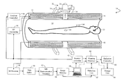
FIG. 1 , a combined magnetic resonance (MR) andradiotherapy system 10 includes amain magnet 12 which generates a temporally uniform B0 field through anexamination region 14. The main magnet can be an annular or bore-type magnet, a C-shaped open magnet, other designs of open magnets, or the like. The magnet includes a magnet radiationtranslucent region 16 which allows a radiation beam, such as gamma (□) rays, x-rays, particle beams, or the like, to pass through the magnet. In one embodiment, themain magnet 12 is a bore-type magnet. The magnet radiationtranslucent region 16 is arranged circumferentially to allow the radiation beam to travel radially through an isocenter of the bore. Gradientmagnetic field coils 18 disposed adjacent the main magnet serve to generate magnetic field gradients along selected axes relative to the B0 magnetic field for spatially encoding magnetic resonance signals, for producing magnetization-spoiling field gradients, or the like. The gradientmagnetic field coils 18 include a gradient radiationtranslucent region 20 aligned to the magnet radiationtranslucent region 16 to allow the radiation beam to travel through themain magnet 12 and gradientmagnetic field coils 18 in a predictable manner to asubject 22 in theexamination region 14, i.e. the absorption throughout the radiationtranslucent regions field gradient coil 18 may include coil segments configured to produce magnetic field gradients in three orthogonal directions, typically longitudinal or z, transverse or x, and vertical or y directions. - The radiation beam originates from a
radiation source 24, such as a linear accelerator or the like, disposed laterally to themain magnet 12 and adjacent to the radiationtranslucent regions source 24 travelling in an unwanted direction. Acollimator 28 helps shaping the beam of radiation to localize the treatment to atarget volume 30. In one embodiment, the collimator is an adjustable collimator, such as a multi-leaf collimator (MLC) or the like, which modulates the radiation beam geometry. The leaves of the MLC allow for conformal shaping of the radiation beam to match the shape of thetarget volume 30 from each angular position of the radiation beam around the subject. - A
radiation source assembly 32, composed of theradiation source 24, theabsorber 26, and thecollimator 28, is mounted on arail system 34 which allows the radiation source assembly to be rotated circumferentially about the radiationtranslucent regions type magnet 12; however, in clinical practice it is not necessary for such a wide range. In another embodiment, a plurality of radiation source assemblies are positioned circumferentially about the radiationtranslucent regions - A radio-frequency (RF)
coil assembly 40, such as a whole-body radio frequency coil, is disposed adjacent to the examination region. The RF coil assembly generates radio frequency pulses for exciting magnetic resonance in aligned dipoles of the subject. The radiofrequency coil assembly 40 also serves to detect magnetic resonance signals emanating from the imaging region. The whole body coil can be of a single coil or a plurality of coil elements as part of an array. The RF coil assembly is configured such that it does not obscure or is radiation translucent adjacent to the radiationtranslucent regions - To acquire magnetic resonance data of a subject, the subject is placed inside the
examination region 14, preferably at or near an isocenter of the main magnetic field. Ascan controller 42 controls agradient controller 44 which causes the gradient coils to apply the selected magnetic field gradient pulses across the imaging region, as may be appropriate to a selected magnetic resonance imaging or spectroscopy sequence. Thescan controller 42 also controls at least oneRF transmitter 46 which causes the RF coil assembly to generate magnetic resonance excitation and manipulation of B1 pulses. The scan controller also controls anRF receiver 48 which is connected to the whole-body or local RF coils to receive magnetic resonance signals therefrom. - The received data from the
receiver 48 is temporarily stored in adata buffer 50 and processed by a magneticresonance data processor 52. The magnetic resonance data processor can perform various functions as are known in the art, including image reconstruction, magnetic resonance spectroscopy, and the like. Reconstructed magnetic resonance images, spectroscopy readouts, and other processed MR data are stored in animage memory 56 and displayed on agraphic user interface 58. Thegraphic user interface 58 also includes a user input device which a clinician can use for controlling thescan controller 42 to select scanning sequences and protocols, and the like. - Prior to receiving radiotherapy, a
planning processor 60, automatically or by user guidance, generates a fractionated radiation therapy plan; each therapy plan includes a plurality of fractions or radiation doses. Each radiation dose includes a prescribed radiation dose, a plurality of radiation beam trajectories, and at least one radiation beam geometry (cross section). The amount of radiation used in radiotherapy is measured in grays (Gy), and varies depending on the type, size, and stage of the tumor being treated. For example, a radiation therapy plan which mandates a radiation dose of 60 Gy can be fractionated into 30 radiation dosage plans of 2 Gy, wherein each radiation dosage plan is administered five days a week for a total of six weeks. In each session, the radiation is distributed over a plurality of trajectories, e.g. 20, along which the same or varying portions of the session dose is delivered. Typically, radiation dosage plan for an adult is 1.8-2.0 Gy and 1.5-1.8 Gy for a child. - To determine the radiation beam trajectories and geometry, a
detection unit 62 detects thetarget volume 30 and non-target volumes, which will be described in detail later, by determining their contours from high-resolution 3D images by using image processing techniques and/or models that describe to volumes. Image processing techniques may include any combination of automatic or semi-automatic segmentation, edge detection, principal components analysis, or the like and can be combined with a model that describes the volumes' shape, texture, motion, or the like to further enhance detection. The determined contours are stored in memory within thedetection unit 62 itself for later use. In one embodiment, thehigh resolution 3D image representation is an MR image representation acquired from the combined MR andradiotherapy system 10 and is retrieved from theimage memory 56 for contour delineation. Alternatively, thehigh resolution 3D image representation can be acquired using other imaging modalities, e.g. computed tomography (CT), x-ray, x-ray fluoroscopy, ultrasound, or the like. - The
planning processor 60 uses the determined contours to generate the individual radiation doses and stores them in memory within the processor itself. Certain non-target volumes, such as radiation blocking or attenuating tissue and sensitive tissue like tissue, organs, glands, or the like, should avoid receiving radiation. The planning processor determines beam trajectories which maximize radiation exposure to target volume while sparing non-target volumes from unwanted damage. Unfortunately, the position and shape of these volumes can fluctuate on a daily basis due to a number of physiological changes such as breathing, bladder volume, lung inflation/deflation, weight gain/loss, tumor size, daily variations in organ position, or the like. Instead of over compensating by irradiating a slightly larger area or generating a new radiation therapy plan altogether, the current radiation therapy plan can be updated by determining the dose delivered to each part of the target and non-target volumes after each treatment. A subsequent radiation dose, or all of the subsequent doses, can be altered based on the delivered radiation dose. - With reference to
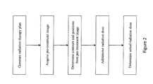
FIG. 2 , in one aspect, after the radiation dose is delivered, the actual dose delivered to each voxel of thetarget 30 and non-target volumes is determined based on a pre-treatment image. Prior to administration of a radiation dose, thescanner controller 42 controls the MR system to acquire a 3D pre-treatment image representation of thetarget volume 30 and non-target volumes. The pre-treatment image can be a low-resolution 3D image representation from which thedetection unit 62 determines the contours and positions of thetarget volume 30 and the non-target volumes. Theplanning processor 60 aligns thecurrent target volume 30 position to the coordinate system of theradiation source assembly 32. Optionally, surgically implanted markers and/or landmarks can be used to ease alignment. Aradiation controller 64 controls theradiation source assembly 32, i.e. its rotational position, the leaves of theMLC 28, and theradiation source 24, to administer treatment at the beam trajectories and geometry according to the current radiation dose. After treatment, adosage unit 66 uses the current beam trajectories, current beam geometry, and the determined contours and/or positions from the pre-treatment image representation to determine the actual radiation dose delivered to each voxel of thetarget volume 30 and non-target volumes. Theplanning processor 60 updates the remaining radiation therapy plan, i.e. at least one or all of the subsequent radiation doses, according to the actual radiation delivered to thetarget volume 30 and non-target volumes. - With reference to
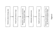
FIG. 3 , in a second aspect, after the radiation dose is delivered, the actual dose delivered to each voxel of thetarget 30 and non-target volumes is determined based on a pre-treatment image and a post-treatment image. After the administration of a radiation dose, thescanner controller 42 controls the MR system to acquire a post-treatment image representation of thetarget volume 30 and non-target volumes. Thedetection unit 62 determines the contours and positions of thetarget volume 30 and the non-target volumes. Thedosage unit 66 determines the actual radiation dose delivered to each voxel of thetarget volume 30 and non-target volumes based on the current beam trajectories, current beam geometry, and changes of the determined contours and/or positions between the pre-treatment and post-treatment image representations. By comparing the position of thetarget 30 and non-target volumes in the pre-treatment and post-treatment image representations, the accuracy of the determined actual dose can be improved. Theplanning processor 60 updates the remaining radiation therapy plan, i.e. at least one or all of the subsequent radiation doses, according to the actual radiation delivered to thetarget volume 30 and non-target volumes. - With reference to
FIG. 4 , in a third aspect, after the radiation dose is delivered, the actual dose delivered to each voxel of thetarget 30 and non-target volumes is determined based on a pre-treatment image and a motion model. Prior to administration of a radiation dose, thescanner controller 42 controls the MR system to acquire a 3D pre-treatment image representation of thetarget volume 30 and non-target volumes and acquire a motion signal from anexternal sensor 68, e.g. a respiratory sensor, ECG sensor, or the like. Thedetection unit 62 determines the contours and positions of thetarget volume 30 and the non-target volumes and determines parameters for the motion model based on the signal from the external sensor. The motion model predicts thetarget 30 and non-target volumes' positions during treatment. Theplanning processor 60 aligns thecurrent target volume 30 position to the coordinate system of theradiation source assembly 32. Optionally, surgically implanted markers and/or landmarks can be used to simplify alignment. Theradiation controller 64 controls theradiation source assembly 32, i.e. its rotational position, the leaves of theMLC 28, and theradiation source 24, to administer treatment at the beam trajectories and geometry according to the current radiation dose. After treatment, thedosage unit 66 uses the current beam trajectories, current beam geometry, and the determined contours and/or positions from the pre-treatment image representation and the determined motion model to determine the actual radiation dose delivered to each voxel of thetarget volume 30 and non-target volumes. By predicting thetarget 30 and non-target volumes' positions during treatment, the accuracy of the determined actual dose can be improved. Theplanning processor 60 updates the remaining radiation therapy plan, i.e. at least one or all of the subsequent radiation doses, according to the actual radiation delivered to thetarget volume 30 and non-target volumes. - With reference to
FIG. 5 , in a fourth aspect, after the radiation dose is delivered, the actual dose delivered to each voxel of thetarget 30 and non-target volumes is determined based on a pre-treatment image and a plurality of 3D intra-treatment images. Prior to administration of the radiation dose, thescanner controller 42 controls the combined MR andradiotherapy system 10 to acquire a 3D pre-treatment image representation of thetarget volume 30 and non-target volumes. Thedetection unit 62 determines the contours and positions of thetarget volume 30 and the non-target volumes from which theplanning processor 60 aligns thecurrent target volume 30 position to the coordinate system of theradiation source assembly 32. Optionally, surgically implanted markers and/or landmarks can be used to simplify alignment. Aradiation controller 64 controls theradiation source assembly 32, i.e. its rotational position, the leaves of theMLC 28, and theradiation source 24, to administer treatment at the beam trajectories and geometry according to the current radiation dose. During the treatment, thescanner controller 42 controls the combined MR andradiotherapy system 10 to acquire a plurality of 3D intra-treatment image representations of thetarget volume 30 and the non-target volumes. After treatment, thedetection unit 62 determines the contours and positions of thetarget volume 30 and the non-target volumes from the intra-treatment image representations. Thedosage unit 66 uses the current beam trajectories, current beam geometry, and the determined contours and/or positions from the pre-treatment and intra-treatment image representations to determine the actual radiation dose delivered to each voxel of thetarget volume 30 and non-target volumes. By periodically monitoring the actual position of thetarget volume 30 and the non-target volumes during treatment, the accuracy of the determined actual dose can be improved. The slower time-scale of the 3D intra-treatment image representation can account for respiratory motion. Theplanning processor 60 updates the remaining radiation therapy plan, i.e. at least one or all of the subsequent radiation doses, according to the actual radiation delivered to thetarget volume 30 and non-target volumes. - With reference to
FIG. 6 , in a fifth aspect, after the radiation dose is delivered, the actual dose delivered to each voxel of thetarget 30 and non-target volumes is determined based on a pre-treatment image and a plurality of 2D/1D intra-treatment images. The shorter time interval between 2D intra-treatment images and even shorter time interval between 1D navigator pulses can account for faster pulsatile motion of the volumes. Prior to administration of the radiation dose, thescanner controller 42 controls the combined MR andradiotherapy system 10 to acquire a 3D pre-treatment image representation of thetarget volume 30 and non-target volumes. Thedetection unit 62 determines the contours and positions of thetarget volume 30 and the non-target volumes from which theplanning processor 60 aligns thecurrent target volume 30 position to the coordinate system of theradiation source assembly 32. Optionally, surgically implanted markers and/or landmarks can be used to simplify alignment. Aradiation controller 64 controls theradiation source assembly 32, i.e. its rotational position, the leaves of theMLC 28, and theradiation source 24, to administer treatment at the beam trajectories and geometry according to the current radiation dose. During the treatment, thescanner controller 42 controls the combined MR andradiotherapy system 10 to acquire a plurality of 2D/1D intra-treatment image representations of thetarget volume 30 and the non-target volumes. After treatment, thedetection unit 62 determines the contours and positions of thetarget volume 30 and the non-target volumes from the 2D/1D intra-treatment image representations. Thedosage unit 66 uses the current beam trajectories, current beam geometry, and the determined contours and/or positions from the pre-treatment and intra-treatment image representations to determine the actual radiation dose delivered to each voxel of thetarget volume 30 and non-target volumes. By monitoring the actual position of thetarget volume 30 and the non-target volumes during treatment at a higher time resolution, the accuracy of the determined actual dose can be improved. Theplanning processor 60 updates the remaining radiation therapy plan, i.e. at least one or all of the subsequent radiation doses, according to the actual radiation delivered to thetarget volume 30 and non-target volumes. Alternatively, thedetection unit 62 determines a motion model based on the 2D/1D intra-treatment image representations and the motion model is used to determine the actual radiation dose. - In one embodiment, the
planning processor 60 updates the remaining radiation therapy plan, i.e. at least one or all of the subsequent radiation doses, automatically. In another embodiment, the radiation plan is updated under user guidance, e.g. by a physician or clinician. The physician verifies the detection of the contours and positions of thetarget 30 and non-target volumes on thegraphic user interface 58. The high resolution image representation used in determining the therapy plan, pre-treatment image representations, intra-treatment image representations, and post-treatment image representations are displayed on thegraphic user interface 58 with the contours and positions of volumes delineated. Using the input device, the physician can identify thetarget volume 30 and non-target volumes, i.e. sensitive tissue, organs, or the like. - In another embodiment, the
planning processor 60 registers all image representations of thetarget 30 and non-target volumes and displays the registered image representations on thegraphic user interface 58 for evaluation by a physician. Based on changes to the volumes throughout time points during the therapy plan, the physician can then choose whether to proceed with the current therapy plan, update the remaining radiation doses of the therapy plan, or cancel the therapy plan. Alternatively, theplanning processor 60 displays the actual radiation dose delivered to each voxel of thetarget volume 30 and non-target volumes as an intensity of color map registered to one of the high resolution image representation used in determining the therapy plan, pre-treatment image representations, intra-treatment image representations, or post-treatment image representations for evaluation by the physician. - In another embodiment, a contrast-enhancing agent, e.g. gadolinium (Gd) based, super-paramagnetic iron oxide (SPIO) and ultra-small SPIO (USPIO) based, manganese (Mn) based, or the like, is introduced into the subject 22 to improve contrast of MR image representations. A contrast enhancing agent can improve contour detection and model parameter accuracy. The contrast enhancing agent is administered prior to acquiring a high-resolution, volumetric image representation for generating a radiation therapy plan and is administered prior to acquiring a pre-treatment image representation for updating the radiation therapy plan.
- The invention has been described with reference to the preferred embodiments. Modifications and alterations may occur to others upon reading and understanding the preceding detailed description. It is intended that the invention be constructed as including all such modifications and alterations insofar as they come within the scope of the appended claims or the equivalents thereof.
Claims (20)
Priority Applications (1)
| Application Number | Priority Date | Filing Date | Title |
|---|---|---|---|
| US13/496,208 US9188654B2 (en) | 2009-10-06 | 2010-09-16 | Retrospective calculation of radiation dose and improved therapy planning |
Applications Claiming Priority (3)
| Application Number | Priority Date | Filing Date | Title |
|---|---|---|---|
| US24897509P | 2009-10-06 | 2009-10-06 | |
| PCT/IB2010/054189 WO2011042820A1 (en) | 2009-10-06 | 2010-09-16 | Retrospective calculation of radiation dose and improved therapy planning |
| US13/496,208 US9188654B2 (en) | 2009-10-06 | 2010-09-16 | Retrospective calculation of radiation dose and improved therapy planning |
Related Parent Applications (1)
| Application Number | Title | Priority Date | Filing Date |
|---|---|---|---|
| PCT/IB2010/054189 A-371-Of-International WO2011042820A1 (en) | 2009-10-06 | 2010-09-16 | Retrospective calculation of radiation dose and improved therapy planning |
Related Child Applications (1)
| Application Number | Title | Priority Date | Filing Date |
|---|---|---|---|
| US14/881,472 Division US9511244B2 (en) | 2009-10-06 | 2015-10-13 | Retrospective calculation of radiation dose and improved therapy planning |
Publications (2)
| Publication Number | Publication Date |
|---|---|
| US20120184841A1 true US20120184841A1 (en) | 2012-07-19 |
| US9188654B2 US9188654B2 (en) | 2015-11-17 |
Family
ID=43446561
Family Applications (2)
| Application Number | Title | Priority Date | Filing Date |
|---|---|---|---|
| US13/496,208 Active 2031-05-12 US9188654B2 (en) | 2009-10-06 | 2010-09-16 | Retrospective calculation of radiation dose and improved therapy planning |
| US14/881,472 Active US9511244B2 (en) | 2009-10-06 | 2015-10-13 | Retrospective calculation of radiation dose and improved therapy planning |
Family Applications After (1)
| Application Number | Title | Priority Date | Filing Date |
|---|---|---|---|
| US14/881,472 Active US9511244B2 (en) | 2009-10-06 | 2015-10-13 | Retrospective calculation of radiation dose and improved therapy planning |
Country Status (6)
| Country | Link |
|---|---|
| US (2) | US9188654B2 (en) |
| EP (1) | EP2486417B1 (en) |
| JP (1) | JP5706901B2 (en) |
| CN (1) | CN102576060B (en) |
| RU (1) | RU2545097C2 (en) |
| WO (1) | WO2011042820A1 (en) |
Cited By (18)
| Publication number | Priority date | Publication date | Assignee | Title |
|---|---|---|---|---|
| US20150209600A1 (en) * | 2012-07-27 | 2015-07-30 | Koninklijke Philips N.V. | 3d imaging method for accurate in-plane tracking of lesion to be treated using mrgrt |
| WO2016070190A1 (en) * | 2014-10-31 | 2016-05-06 | Siris Medical, Inc. | Physician directed radiation treatment planning |
| US20160136456A1 (en) * | 2013-06-21 | 2016-05-19 | Koninklijke Philips N.V. | Cryostat and system for combined magnetic resonance imaging and radiation therapy |
| US20160213949A1 (en) * | 2013-09-30 | 2016-07-28 | Koninklijke Philips N.V. | Medical instrument for external beam radiotherapy and brachytherapy |
| US20160356869A1 (en) * | 2010-02-24 | 2016-12-08 | Viewray Technologies, Inc. | Split magnetic resonance imaging system |
| US20170095678A1 (en) * | 2015-10-02 | 2017-04-06 | Varian Medical Systems International Ag | Systems and methods for quantifying radiation beam conformity |
| US10254284B2 (en) * | 2015-07-09 | 2019-04-09 | Atomic Oncology Pty Ltd | Method for treating a cancer patient based on atomic therapeutic indexes and radiation |
| US10302661B2 (en) | 2015-07-09 | 2019-05-28 | Atomic Oncology Pty Ltd | Method for treating a cancer patient based on atomic therapeutic indexes and non-radiation therapy |
| CN111569276A (en) * | 2020-05-13 | 2020-08-25 | 山东省肿瘤防治研究院(山东省肿瘤医院) | A carrier-based positioning radiotherapy device and working method |
| US20210298630A1 (en) * | 2014-11-26 | 2021-09-30 | Viewray Technologies, Inc. | Magnetic resonance imaging receive coil assembly |
| US20220070416A1 (en) * | 2020-09-01 | 2022-03-03 | Boston Scientific Scimed, Inc. | Image processing systems and methods of using the same |
| US20220203134A1 (en) * | 2020-12-30 | 2022-06-30 | Varian Medical Systems International Ag | Beam-off motion thresholds in radiation therapy based on breath-hold level determination |
| CN114832245A (en) * | 2017-07-21 | 2022-08-02 | 瓦里安医疗系统国际股份公司 | Triggered therapy system and method |
| EP4325235A3 (en) * | 2015-02-11 | 2024-05-22 | ViewRay Technologies, Inc. | Planning and control for magnetic resonance guided radiation therapy |
| US12025684B2 (en) | 2021-08-04 | 2024-07-02 | Viewray Systems, Inc. | RF coil assemblies |
| US12270873B2 (en) | 2013-03-12 | 2025-04-08 | Viewray Systems, Inc. | Radio frequency transmit coil for magnetic resonance imaging system |
| US12350523B2 (en) | 2021-10-22 | 2025-07-08 | Viewray Systems, Inc. | MRI guided radiotherapy |
| US12478803B2 (en) | 2021-10-22 | 2025-11-25 | Viewray Systems, Inc. | Systems, methods and computer software for optimized radiation therapy |
Families Citing this family (16)
| Publication number | Priority date | Publication date | Assignee | Title |
|---|---|---|---|---|
| EP2558162B1 (en) * | 2010-04-15 | 2020-06-10 | Elekta AB (PUBL) | Radiotherapy and imaging apparatus |
| GB2491800A (en) * | 2011-03-30 | 2012-12-19 | Elekta Ab | Slip ring power source for radiotherapy apparatus |
| GB2489681B (en) * | 2011-03-30 | 2017-11-22 | Elekta Ab | Radiotherapeutic apparatus |
| GB2489680B (en) * | 2011-03-30 | 2017-11-08 | Elekta Ab | Radiotherapeutic apparatus |
| GB2490325B (en) | 2011-04-21 | 2013-04-10 | Siemens Plc | Combined MRI and radiation therapy equipment |
| RU2631910C2 (en) * | 2012-09-18 | 2017-09-28 | Конинклейке Филипс Н.В. | Linear accelerator directed by magnetic resonance |
| GB2507585B (en) * | 2012-11-06 | 2015-04-22 | Siemens Plc | MRI magnet for radiation and particle therapy |
| DE102013214356B4 (en) * | 2013-07-23 | 2015-02-12 | Siemens Aktiengesellschaft | Optimization of a pulse sequence for a magnetic resonance imaging system |
| US11278741B2 (en) * | 2014-03-13 | 2022-03-22 | Koninklijke Philips N.V. | Magnetic resonance antenna with electronic dosimeters |
| US10046177B2 (en) | 2014-06-18 | 2018-08-14 | Elekta Ab | System and method for automatic treatment planning |
| KR101689130B1 (en) * | 2014-12-23 | 2016-12-23 | 재단법인 아산사회복지재단 | Mucosal dose control photon beam radiotherapy apparatus using magnetic fields |
| CN105233425A (en) * | 2015-09-10 | 2016-01-13 | 上海联影医疗科技有限公司 | A magnetic resonance image-guided radiotherapy system |
| WO2018115022A1 (en) * | 2016-12-23 | 2018-06-28 | Koninklijke Philips N.V. | Ray tracing for the detection and avoidance of collisions between radiotherapy devices and patient |
| CN110579789A (en) * | 2019-06-03 | 2019-12-17 | 南华大学 | A Retrospective Dosimetry Method with High Throughput and Stable Signal Intensity |
| CN110579788A (en) * | 2019-06-03 | 2019-12-17 | 南华大学 | A radiation dose measurement method with low detection limit |
| US12551727B2 (en) * | 2021-01-26 | 2026-02-17 | Ardos Aps | System and method for dose guidance and repeated estimation of final delivered radiation dose for a radiotherapy system |
Citations (6)
| Publication number | Priority date | Publication date | Assignee | Title |
|---|---|---|---|---|
| US20040024434A1 (en) * | 2002-04-01 | 2004-02-05 | The Johns Hopkins University School Of Medicine | Device, systems and methods for localized heating of a vessel and/or in combination with MR/NMR imaging of the vessel and surrounding tissue |
| US6806712B2 (en) * | 2000-03-22 | 2004-10-19 | Specialty Magnetics Limited | Magnetic resonance imaging apparatus and method |
| US20050111621A1 (en) * | 2003-10-07 | 2005-05-26 | Robert Riker | Planning system, method and apparatus for conformal radiation therapy |
| US20070041497A1 (en) * | 2005-07-22 | 2007-02-22 | Eric Schnarr | Method and system for processing data relating to a radiation therapy treatment plan |
| US7574251B2 (en) * | 2005-07-22 | 2009-08-11 | Tomotherapy Incorporated | Method and system for adapting a radiation therapy treatment plan based on a biological model |
| US20100292564A1 (en) * | 2009-05-18 | 2010-11-18 | Cantillon Murphy Padraig J | System and Method For Magnetic-Nanoparticle, Hyperthermia Cancer Therapy |
Family Cites Families (10)
| Publication number | Priority date | Publication date | Assignee | Title |
|---|---|---|---|---|
| US6719683B2 (en) * | 2000-09-30 | 2004-04-13 | Brainlab Ag | Radiotherapy treatment planning with multiple inverse planning results |
| WO2005031629A1 (en) | 2003-09-29 | 2005-04-07 | Koninklijke Philips Electronics, N.V. | Method and device for planning a radiation therapy |
| US8989349B2 (en) * | 2004-09-30 | 2015-03-24 | Accuray, Inc. | Dynamic tracking of moving targets |
| US8232535B2 (en) | 2005-05-10 | 2012-07-31 | Tomotherapy Incorporated | System and method of treating a patient with radiation therapy |
| JP2009525114A (en) | 2006-02-01 | 2009-07-09 | コーニンクレッカ フィリップス エレクトロニクス エヌ ヴィ | Improved radiotherapy planning procedure |
| US7693257B2 (en) * | 2006-06-29 | 2010-04-06 | Accuray Incorporated | Treatment delivery optimization |
| CN100431642C (en) * | 2006-12-29 | 2008-11-12 | 成都川大奇林科技有限责任公司 | Method for determining radiating field output dose accurately in conformalradiotherapy |
| DE102008007245B4 (en) * | 2007-02-28 | 2010-10-14 | Siemens Aktiengesellschaft | Combined radiotherapy and magnetic resonance device |
| JP5197024B2 (en) * | 2008-01-09 | 2013-05-15 | 株式会社東芝 | Radiotherapy system, radiotherapy support apparatus, and radiotherapy support program |
| US8238516B2 (en) | 2008-01-09 | 2012-08-07 | Kabushiki Kaisha Toshiba | Radiotherapy support apparatus |
-
2010
- 2010-09-16 CN CN201080044961.2A patent/CN102576060B/en active Active
- 2010-09-16 JP JP2012532686A patent/JP5706901B2/en active Active
- 2010-09-16 US US13/496,208 patent/US9188654B2/en active Active
- 2010-09-16 WO PCT/IB2010/054189 patent/WO2011042820A1/en not_active Ceased
- 2010-09-16 RU RU2012118760/28A patent/RU2545097C2/en not_active IP Right Cessation
- 2010-09-16 EP EP10766117.5A patent/EP2486417B1/en active Active
-
2015
- 2015-10-13 US US14/881,472 patent/US9511244B2/en active Active
Patent Citations (7)
| Publication number | Priority date | Publication date | Assignee | Title |
|---|---|---|---|---|
| US6806712B2 (en) * | 2000-03-22 | 2004-10-19 | Specialty Magnetics Limited | Magnetic resonance imaging apparatus and method |
| US20040024434A1 (en) * | 2002-04-01 | 2004-02-05 | The Johns Hopkins University School Of Medicine | Device, systems and methods for localized heating of a vessel and/or in combination with MR/NMR imaging of the vessel and surrounding tissue |
| US20080208034A1 (en) * | 2002-04-01 | 2008-08-28 | The Johns Hopkins University | Device, systems and methods for localized heating of a vessel and/or in combination with mr/nmr imaging of the vessel and surrounding tissue |
| US20050111621A1 (en) * | 2003-10-07 | 2005-05-26 | Robert Riker | Planning system, method and apparatus for conformal radiation therapy |
| US20070041497A1 (en) * | 2005-07-22 | 2007-02-22 | Eric Schnarr | Method and system for processing data relating to a radiation therapy treatment plan |
| US7574251B2 (en) * | 2005-07-22 | 2009-08-11 | Tomotherapy Incorporated | Method and system for adapting a radiation therapy treatment plan based on a biological model |
| US20100292564A1 (en) * | 2009-05-18 | 2010-11-18 | Cantillon Murphy Padraig J | System and Method For Magnetic-Nanoparticle, Hyperthermia Cancer Therapy |
Cited By (33)
| Publication number | Priority date | Publication date | Assignee | Title |
|---|---|---|---|---|
| US10571536B2 (en) * | 2010-02-24 | 2020-02-25 | Viewray Technologies, Inc. | Split magnetic resonance imaging system |
| US20160356869A1 (en) * | 2010-02-24 | 2016-12-08 | Viewray Technologies, Inc. | Split magnetic resonance imaging system |
| US20150209600A1 (en) * | 2012-07-27 | 2015-07-30 | Koninklijke Philips N.V. | 3d imaging method for accurate in-plane tracking of lesion to be treated using mrgrt |
| US9498648B2 (en) * | 2012-07-27 | 2016-11-22 | Koninklijke Philips N.V. | 3D imaging method for accurate in-plane tracking of lesion to be treated using MRgRT |
| US12270873B2 (en) | 2013-03-12 | 2025-04-08 | Viewray Systems, Inc. | Radio frequency transmit coil for magnetic resonance imaging system |
| US10729918B2 (en) * | 2013-06-21 | 2020-08-04 | Koninklijke Philips N.V. | Cryostat and system for combined magnetic resonance imaging and radiation therapy |
| US20160136456A1 (en) * | 2013-06-21 | 2016-05-19 | Koninklijke Philips N.V. | Cryostat and system for combined magnetic resonance imaging and radiation therapy |
| US20160213949A1 (en) * | 2013-09-30 | 2016-07-28 | Koninklijke Philips N.V. | Medical instrument for external beam radiotherapy and brachytherapy |
| US10092775B2 (en) * | 2013-09-30 | 2018-10-09 | Koninklijke Philips N.V. | Medical instrument for external beam radiotherapy and brachytherapy |
| US10293179B2 (en) | 2014-10-31 | 2019-05-21 | Siris Medical, Inc. | Physician directed radiation treatment planning |
| US11020613B2 (en) | 2014-10-31 | 2021-06-01 | Siris Medical, Inc. | Physician directed radiation treatment planning |
| WO2016070190A1 (en) * | 2014-10-31 | 2016-05-06 | Siris Medical, Inc. | Physician directed radiation treatment planning |
| US11642040B2 (en) * | 2014-11-26 | 2023-05-09 | Viewray Technologies, Inc. | Magnetic resonance imaging receive coil assembly |
| US20210298630A1 (en) * | 2014-11-26 | 2021-09-30 | Viewray Technologies, Inc. | Magnetic resonance imaging receive coil assembly |
| EP4325235A3 (en) * | 2015-02-11 | 2024-05-22 | ViewRay Technologies, Inc. | Planning and control for magnetic resonance guided radiation therapy |
| US10254284B2 (en) * | 2015-07-09 | 2019-04-09 | Atomic Oncology Pty Ltd | Method for treating a cancer patient based on atomic therapeutic indexes and radiation |
| US10302661B2 (en) | 2015-07-09 | 2019-05-28 | Atomic Oncology Pty Ltd | Method for treating a cancer patient based on atomic therapeutic indexes and non-radiation therapy |
| US10729920B2 (en) * | 2015-10-02 | 2020-08-04 | Varian Medical Systems International Ag | Systems and methods for quantifying radiation beam conformity |
| US20170095678A1 (en) * | 2015-10-02 | 2017-04-06 | Varian Medical Systems International Ag | Systems and methods for quantifying radiation beam conformity |
| CN114832245A (en) * | 2017-07-21 | 2022-08-02 | 瓦里安医疗系统国际股份公司 | Triggered therapy system and method |
| CN111569276A (en) * | 2020-05-13 | 2020-08-25 | 山东省肿瘤防治研究院(山东省肿瘤医院) | A carrier-based positioning radiotherapy device and working method |
| US12042132B2 (en) * | 2020-09-01 | 2024-07-23 | Boston Scientific Scimed, Inc. | Image processing systems and methods of using the same |
| US20220070416A1 (en) * | 2020-09-01 | 2022-03-03 | Boston Scientific Scimed, Inc. | Image processing systems and methods of using the same |
| US12342990B2 (en) * | 2020-09-01 | 2025-07-01 | Boston Scientific Scimed, Inc. | Image processing systems and methods of using the same |
| US11700997B2 (en) * | 2020-09-01 | 2023-07-18 | Boston Scientific Scimed, Inc. | Image processing systems and methods of using the same |
| US20230284888A1 (en) * | 2020-09-01 | 2023-09-14 | Boston Scientific Scimed, Inc. | Image processing systems and methods of using the same |
| US20240335103A1 (en) * | 2020-09-01 | 2024-10-10 | Boston Scientific Scimed, Inc. | Image processing systems and methods of using the same |
| US11433257B2 (en) * | 2020-12-30 | 2022-09-06 | Varian Medical Systems International Ag | Beam-off motion thresholds in radiation therapy based on breath-hold level determination |
| US11878189B2 (en) | 2020-12-30 | 2024-01-23 | Siemens Healthineeers International Ag | Beam-off motion thresholds in radiation therapy based on breath-hold level determination |
| US20220203134A1 (en) * | 2020-12-30 | 2022-06-30 | Varian Medical Systems International Ag | Beam-off motion thresholds in radiation therapy based on breath-hold level determination |
| US12025684B2 (en) | 2021-08-04 | 2024-07-02 | Viewray Systems, Inc. | RF coil assemblies |
| US12350523B2 (en) | 2021-10-22 | 2025-07-08 | Viewray Systems, Inc. | MRI guided radiotherapy |
| US12478803B2 (en) | 2021-10-22 | 2025-11-25 | Viewray Systems, Inc. | Systems, methods and computer software for optimized radiation therapy |
Also Published As
| Publication number | Publication date |
|---|---|
| RU2012118760A (en) | 2013-11-20 |
| JP5706901B2 (en) | 2015-04-22 |
| EP2486417A1 (en) | 2012-08-15 |
| JP2013506519A (en) | 2013-02-28 |
| CN102576060B (en) | 2016-05-11 |
| CN102576060A (en) | 2012-07-11 |
| EP2486417B1 (en) | 2019-07-31 |
| US9188654B2 (en) | 2015-11-17 |
| US9511244B2 (en) | 2016-12-06 |
| WO2011042820A1 (en) | 2011-04-14 |
| US20160030770A1 (en) | 2016-02-04 |
| RU2545097C2 (en) | 2015-03-27 |
Similar Documents
| Publication | Publication Date | Title |
|---|---|---|
| US9511244B2 (en) | Retrospective calculation of radiation dose and improved therapy planning | |
| US11497937B2 (en) | System for delivering conformal radiation therapy while simultaneously imaging soft tissue | |
| EP2044576A2 (en) | Efficient user interaction with polygonal meshes for medical image segmentation | |
| AU2017208382B2 (en) | System for delivering conformal radiation therapy while simultaneously imaging soft tissue | |
| AU2013201172B2 (en) | System for Delivering Conformal Radiation Therapy While Simultaneously Imaging Soft Tissue | |
| Grigo | Optimization of Magnetic Resonance Imaging in Radiation Oncology | |
| Hacene | Contribution of Magnetic Resonance Imaging (MRI) in Glioblastoma radiotherapy treatment planning and dose calculation | |
| HK1156828B (en) | System for delivering conformal radiation therapy while simultaneously imaging soft tissue |
Legal Events
| Date | Code | Title | Description |
|---|---|---|---|
| AS | Assignment |
Owner name: KONINKLIJKE PHILIPS ELECTRONICS N.V., NETHERLANDS Free format text: ASSIGNMENT OF ASSIGNORS INTEREST;ASSIGNORS:NIELSEN, TIM;BOERNERT, PETER;UHLEMANN, FALK;AND OTHERS;SIGNING DATES FROM 20090923 TO 20090929;REEL/FRAME:027866/0288 |
|
| STCF | Information on status: patent grant |
Free format text: PATENTED CASE |
|
| MAFP | Maintenance fee payment |
Free format text: PAYMENT OF MAINTENANCE FEE, 4TH YEAR, LARGE ENTITY (ORIGINAL EVENT CODE: M1551); ENTITY STATUS OF PATENT OWNER: LARGE ENTITY Year of fee payment: 4 |
|
| MAFP | Maintenance fee payment |
Free format text: PAYMENT OF MAINTENANCE FEE, 8TH YEAR, LARGE ENTITY (ORIGINAL EVENT CODE: M1552); ENTITY STATUS OF PATENT OWNER: LARGE ENTITY Year of fee payment: 8 |