US20120184834A1 - Sensor Catheter Having Reduced Cross-Talk Wiring Arrangements - Google Patents
Sensor Catheter Having Reduced Cross-Talk Wiring Arrangements Download PDFInfo
- Publication number
- US20120184834A1 US20120184834A1 US13/431,332 US201213431332A US2012184834A1 US 20120184834 A1 US20120184834 A1 US 20120184834A1 US 201213431332 A US201213431332 A US 201213431332A US 2012184834 A1 US2012184834 A1 US 2012184834A1
- Authority
- US
- United States
- Prior art keywords
- wires
- wire
- twisted together
- sensor
- wire bundle
- Prior art date
- Legal status (The legal status is an assumption and is not a legal conclusion. Google has not performed a legal analysis and makes no representation as to the accuracy of the status listed.)
- Granted
Links
Images

Classifications
-
- H—ELECTRICITY
- H01—ELECTRIC ELEMENTS
- H01B—CABLES; CONDUCTORS; INSULATORS; SELECTION OF MATERIALS FOR THEIR CONDUCTIVE, INSULATING OR DIELECTRIC PROPERTIES
- H01B11/00—Communication cables or conductors
- H01B11/02—Cables with twisted pairs or quads
- H01B11/04—Cables with twisted pairs or quads with pairs or quads mutually positioned to reduce cross-talk
-
- A—HUMAN NECESSITIES
- A61—MEDICAL OR VETERINARY SCIENCE; HYGIENE
- A61B—DIAGNOSIS; SURGERY; IDENTIFICATION
- A61B5/00—Measuring for diagnostic purposes; Identification of persons
- A61B5/22—Ergometry; Measuring muscular strength or the force of a muscular blow
- A61B5/221—Ergometry, e.g. by using bicycle type apparatus
- A61B5/222—Ergometry, e.g. by using bicycle type apparatus combined with detection or measurement of physiological parameters, e.g. heart rate
-
- A—HUMAN NECESSITIES
- A61—MEDICAL OR VETERINARY SCIENCE; HYGIENE
- A61B—DIAGNOSIS; SURGERY; IDENTIFICATION
- A61B5/00—Measuring for diagnostic purposes; Identification of persons
- A61B5/68—Arrangements of detecting, measuring or recording means, e.g. sensors, in relation to patient
- A61B5/6846—Arrangements of detecting, measuring or recording means, e.g. sensors, in relation to patient specially adapted to be brought in contact with an internal body part, i.e. invasive
- A61B5/6847—Arrangements of detecting, measuring or recording means, e.g. sensors, in relation to patient specially adapted to be brought in contact with an internal body part, i.e. invasive mounted on an invasive device
- A61B5/6852—Catheters
-
- A—HUMAN NECESSITIES
- A61—MEDICAL OR VETERINARY SCIENCE; HYGIENE
- A61B—DIAGNOSIS; SURGERY; IDENTIFICATION
- A61B8/00—Diagnosis using ultrasonic, sonic or infrasonic waves
- A61B8/12—Diagnosis using ultrasonic, sonic or infrasonic waves in body cavities or body tracts, e.g. by using catheters
-
- A—HUMAN NECESSITIES
- A61—MEDICAL OR VETERINARY SCIENCE; HYGIENE
- A61B—DIAGNOSIS; SURGERY; IDENTIFICATION
- A61B8/00—Diagnosis using ultrasonic, sonic or infrasonic waves
- A61B8/44—Constructional features of the ultrasonic, sonic or infrasonic diagnostic device
- A61B8/4444—Constructional features of the ultrasonic, sonic or infrasonic diagnostic device related to the probe
- A61B8/445—Details of catheter construction
-
- A—HUMAN NECESSITIES
- A61—MEDICAL OR VETERINARY SCIENCE; HYGIENE
- A61B—DIAGNOSIS; SURGERY; IDENTIFICATION
- A61B8/00—Diagnosis using ultrasonic, sonic or infrasonic waves
- A61B8/44—Constructional features of the ultrasonic, sonic or infrasonic diagnostic device
- A61B8/4483—Constructional features of the ultrasonic, sonic or infrasonic diagnostic device characterised by features of the ultrasound transducer
-
- A—HUMAN NECESSITIES
- A61—MEDICAL OR VETERINARY SCIENCE; HYGIENE
- A61B—DIAGNOSIS; SURGERY; IDENTIFICATION
- A61B8/00—Diagnosis using ultrasonic, sonic or infrasonic waves
- A61B8/46—Ultrasonic, sonic or infrasonic diagnostic devices with special arrangements for interfacing with the operator or the patient
- A61B8/461—Displaying means of special interest
-
- A—HUMAN NECESSITIES
- A61—MEDICAL OR VETERINARY SCIENCE; HYGIENE
- A61B—DIAGNOSIS; SURGERY; IDENTIFICATION
- A61B8/00—Diagnosis using ultrasonic, sonic or infrasonic waves
- A61B8/52—Devices using data or image processing specially adapted for diagnosis using ultrasonic, sonic or infrasonic waves
- A61B8/5207—Devices using data or image processing specially adapted for diagnosis using ultrasonic, sonic or infrasonic waves involving processing of raw data to produce diagnostic data, e.g. for generating an image
-
- A—HUMAN NECESSITIES
- A61—MEDICAL OR VETERINARY SCIENCE; HYGIENE
- A61M—DEVICES FOR INTRODUCING MEDIA INTO, OR ONTO, THE BODY; DEVICES FOR TRANSDUCING BODY MEDIA OR FOR TAKING MEDIA FROM THE BODY; DEVICES FOR PRODUCING OR ENDING SLEEP OR STUPOR
- A61M25/00—Catheters; Hollow probes
- A61M25/0043—Catheters; Hollow probes characterised by structural features
- A61M25/005—Catheters; Hollow probes characterised by structural features with embedded materials for reinforcement, e.g. wires, coils, braids
-
- A—HUMAN NECESSITIES
- A61—MEDICAL OR VETERINARY SCIENCE; HYGIENE
- A61M—DEVICES FOR INTRODUCING MEDIA INTO, OR ONTO, THE BODY; DEVICES FOR TRANSDUCING BODY MEDIA OR FOR TAKING MEDIA FROM THE BODY; DEVICES FOR PRODUCING OR ENDING SLEEP OR STUPOR
- A61M25/00—Catheters; Hollow probes
- A61M25/0067—Catheters; Hollow probes characterised by the distal end, e.g. tips
- A61M25/0068—Static characteristics of the catheter tip, e.g. shape, atraumatic tip, curved tip or tip structure
-
- H—ELECTRICITY
- H01—ELECTRIC ELEMENTS
- H01R—ELECTRICALLY-CONDUCTIVE CONNECTIONS; STRUCTURAL ASSOCIATIONS OF A PLURALITY OF MUTUALLY-INSULATED ELECTRICAL CONNECTING ELEMENTS; COUPLING DEVICES; CURRENT COLLECTORS
- H01R13/00—Details of coupling devices of the kinds covered by groups H01R12/70 or H01R24/00 - H01R33/00
- H01R13/646—Details of coupling devices of the kinds covered by groups H01R12/70 or H01R24/00 - H01R33/00 specially adapted for high-frequency, e.g. structures providing an impedance match or phase match
- H01R13/6461—Means for preventing cross-talk
- H01R13/6463—Means for preventing cross-talk using twisted pairs of wires
-
- A—HUMAN NECESSITIES
- A61—MEDICAL OR VETERINARY SCIENCE; HYGIENE
- A61B—DIAGNOSIS; SURGERY; IDENTIFICATION
- A61B5/00—Measuring for diagnostic purposes; Identification of persons
- A61B5/02—Detecting, measuring or recording for evaluating the cardiovascular system, e.g. pulse, heart rate, blood pressure or blood flow
- A61B5/024—Measuring pulse rate or heart rate
-
- A—HUMAN NECESSITIES
- A61—MEDICAL OR VETERINARY SCIENCE; HYGIENE
- A61B—DIAGNOSIS; SURGERY; IDENTIFICATION
- A61B5/00—Measuring for diagnostic purposes; Identification of persons
- A61B5/08—Measuring devices for evaluating the respiratory organs
- A61B5/083—Measuring rate of metabolism by using breath test, e.g. measuring rate of oxygen consumption
-
- H—ELECTRICITY
- H01—ELECTRIC ELEMENTS
- H01R—ELECTRICALLY-CONDUCTIVE CONNECTIONS; STRUCTURAL ASSOCIATIONS OF A PLURALITY OF MUTUALLY-INSULATED ELECTRICAL CONNECTING ELEMENTS; COUPLING DEVICES; CURRENT COLLECTORS
- H01R2201/00—Connectors or connections adapted for particular applications
- H01R2201/12—Connectors or connections adapted for particular applications for medicine and surgery
Definitions
- This application relates to medical devices such as catheters that have sensors at their distal tips to which electrical wiring is connected.
- Sensor catheters are used to gather information during medical procedures for diagnosing and treating patients.
- Ultrasonic imaging catheters may be used to gather ultrasonic images of a patient's blood vessels.
- Alternative imaging techniques also may be used, such as magnetic resonance imaging, optical coherence tomography and infrared imaging.
- catheters may be used to gather a variety of physiological parameters such as temperature, pressure, pH, flow velocity and/or volumetric flow. Gradients or changes in physiological parameters across an area of interest may also be determined.
- Sensor catheters are typically connected to control and analysis equipment, which may be used to generate images from raw imaging data and display physiological parameters.
- a number of wires must be run along the length of a typical catheter to connect the control and analysis equipment disposed at the catheter's proximal end to the sensor(s) disposed at the distal catheter tip.
- wires that convey power supply voltages, ground potential, drive signals, and raw sensor signals to and from the catheter sensors. These wires may be organized as a single cable bundle. However, cross-talk or noise among signal wires is a source of interference when using a sensor catheter to gather sensor measurements. This may adversely affect ringdown performance.
- an imaging catheter including improved wiring arrangements to reduce wire-to-wire cross-talk.
- sensor catheters having improved wiring arrangements that reduce wire-to-wire cross-talk.
- the wires are grouped in distinct subgroups such as pairs of wires or groups of three or more wires that carry related signals. Accordingly, a group of seven wires may be divided into two twisted wire pairs and one group of three twisted wires. In this manner, wire-to-wire cross-talk is reduced.
- the two wires that carry sensor signals from the ultrasonic imaging catheter may be grouped together and twisted closely together as a pair.
- cross-talk between the two wires is reduced, especially when compared to wire arrangements in which all of the wires are arranged in a single bundle.
- wires associated with ultrasonic drive signals also may be grouped together as a pair.
- wires carrying power supply and clock signals may be grouped together as a pair.
- sensor catheters having varying signaling needs and signal wires will require different wire subgroup arrangements.
- the resulting wire subgroup arrangements may be twisted together to form a single wire group formed of multiple wire subgroups.
- FIG. 1 is a side view of a previously known sensor catheter system
- FIG. 2 is a side-sectional view of the previously known sensor catheter of FIG. 1 ;
- FIG. 3 is a cross-sectional view of a previously known wire bundle for a sensor catheter
- FIG. 4 is cross-sectional view of a first embodiment of a wiring arrangement for a sensor catheter constructed in accordance with the principles of the present invention
- FIG. 5 is cross-sectional view of a second embodiment of a wiring arrangement for a sensor catheter constructed in accordance with the principles of the present invention.
- FIG. 6 is cross-sectional view of a third embodiment of a wiring arrangement for a sensor catheter of the present invention.
- a previously known sensor catheter system 10 comprises catheter 12 including proximal end 12 a attached to processing equipment 14 and distal end 12 b including sensor assembly 16 comprising one or more sensors.
- sensor assembly 16 may includes a temperature sensor, a pressure sensor, a pH sensor, a flow velocity sensor and/or a volumetric flow sensor for measuring temperature, pressure, pH, flow velocity and flow volume.
- sensor assembly 16 may include sensors other than those listed above.
- Sensor assembly 16 also may include an imaging sensor, such as an ultrasound, magnetic resonance, optical coherence tomography or infrared imaging sensor. Imaging sensors are typically used to gather images from locations inside a patient's body during surgical and diagnostic procedures. Catheter 12 may be configured to gather images from inside a patient's blood vessels during percutaneous procedures such as cardiological or peripheral intervention. An illustrative catheter that may be used for ultrasound applications is described in commonly assigned U.S. patent application Ser. No. 10/233,870, filed Aug. 29, 2002.
- Sensor assembly 16 may include an ultrasound sensor that transmits signals to processing equipment 14 , which processes the signal data and displays the resulting images on a suitable display screen.
- sensor assembly 16 may include other sensors that transmit different signals to the processing equipment.
- Processing equipment 14 also transmits signals that control the operation of sensor assembly 16 .
- processing equipment 14 transmits drive signals for one or more transducer elements disposed within the sensor assembly. These drive signals cause the transducer elements to emit acoustic vibrations directed towards a target area within the patient's body.
- Power supply signals and clock signals (e.g., for synchronizing the timing of circuitry within sensor assembly 16 ) also may be transmitted to sensor assembly 16 from processing equipment 14 via wire bundle 18 .
- clock signals e.g., for synchronizing the timing of circuitry within sensor assembly 16
- a previously known wiring arrangement 20 for a sensor catheter comprises a single wire bundle having six individual wires 20 a radially surrounding central wire 20 b.
- Wiring arrangement further comprises outer sheath 21 for retaining the wires 20 a and 20 b.
- This arrangement has the advantage of being relatively compact, but suffers from a relatively high degree of wire-to-wire cross-talk.
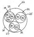
- Wiring arrangement 22 comprises first wire bundle 24 contained within sheath 25 , second wire bundle 26 contained within sheath 27 and third wire bundle 28 contained within sheath 29 .
- First wire bundle 24 includes wires 24 a and 24 b, which are twisted together to assist in electrically isolating the wires from the environment, thereby reducing electromagnetic signal interference among the individual wires.
- second wire bundle 26 includes wires 26 a and 26 b that are twisted together;
- third wire bundle 28 includes wires 28 a, 28 b and 28 c that are twisted together. All three wire bundles 24 , 26 and 28 are twisted together to form wiring arrangement 22 and housed within outer sheath 30 .
- Wiring arrangement 32 comprises first wire bundle 34 contained within sheath 35 , second wire bundle 36 contained within sheath 37 and third wire bundle 38 contained within sheath 39 .
- First wire bundle 34 includes wires 34 a and 34 b, which are twisted together to assist in electrically isolating the wires from the environment, thereby reducing electromagnetic signal interference among the individual wires.
- second wire bundle 36 includes wires 36 a and 36 b that are twisted together;
- third wire bundle 38 includes wires 38 a, 38 b and 38 c that are twisted together.
- wire bundles 34 , 36 and 38 of the embodiment of FIG. 5 are not twisted and retained within an outer sheath.
- Wiring arrangement 42 comprises first wire bundle 44 contained within sheath 45 , second wire bundle 46 contained within sheath 47 and third wire bundle 48 contained within sheath 49 .
- the first pair of wires includes wires 44 a, 44 b and 44 c, which are twisted together to assist in electrically isolating the wires from the environment, thereby reducing electromagnetic signal interference among the individual wires.
- second wire bundle 46 includes wires 46 a, 46 b and 46 c that are twisted together;
- third wire bundle 48 includes wires 48 a, 48 b and 48 c that are twisted together. All three wire bundles 44 , 46 and 48 are twisted together to form wiring arrangement 42 and contained within an outer sheath 50 .
- Twisting the wires in the wire bundles has been observed to reduce electromagnetic interference among the wires.
- the wires are twisted in a clockwise direction, while in others the wires may be twisted in a counter-clockwise direction.
- wires within different bundles may be twisted in different directions depending upon the application of the sensor catheter.
- multiple wire bundles may be twisted together to form a single wire group.
- the direction of wire bundle twisting preferably is opposite to the direction in which individual wires are twisted when forming the multiple wire bundles.
- FIGS. 4-6 are merely illustrative. As would be appreciated by those of skill in the art, many different wiring arrangements are possible without departing from the scope of the present invention.
- the wiring arrangement may include 2 or more wire bundles, each wire bundle including two or more individual wires.
Landscapes
- Health & Medical Sciences (AREA)
- Life Sciences & Earth Sciences (AREA)
- Engineering & Computer Science (AREA)
- General Health & Medical Sciences (AREA)
- Animal Behavior & Ethology (AREA)
- Biophysics (AREA)
- Biomedical Technology (AREA)
- Heart & Thoracic Surgery (AREA)
- Veterinary Medicine (AREA)
- Public Health (AREA)
- Molecular Biology (AREA)
- Physics & Mathematics (AREA)
- Pathology (AREA)
- Medical Informatics (AREA)
- Surgery (AREA)
- Nuclear Medicine, Radiotherapy & Molecular Imaging (AREA)
- Radiology & Medical Imaging (AREA)
- Pulmonology (AREA)
- Hematology (AREA)
- Anesthesiology (AREA)
- Cardiology (AREA)
- Physical Education & Sports Medicine (AREA)
- Physiology (AREA)
- Computer Vision & Pattern Recognition (AREA)
- Gynecology & Obstetrics (AREA)
- Media Introduction/Drainage Providing Device (AREA)
- Ultra Sonic Daignosis Equipment (AREA)
Abstract
Description
- This application claims the benefit of U.S. provisional patent application Ser. No. 60/413,267, filed Sep. 23, 2002.
- This application relates to medical devices such as catheters that have sensors at their distal tips to which electrical wiring is connected.
- Sensor catheters are used to gather information during medical procedures for diagnosing and treating patients. Ultrasonic imaging catheters, for example, may be used to gather ultrasonic images of a patient's blood vessels. Alternative imaging techniques also may be used, such as magnetic resonance imaging, optical coherence tomography and infrared imaging. During certain procedures, catheters may be used to gather a variety of physiological parameters such as temperature, pressure, pH, flow velocity and/or volumetric flow. Gradients or changes in physiological parameters across an area of interest may also be determined.
- Sensor catheters are typically connected to control and analysis equipment, which may be used to generate images from raw imaging data and display physiological parameters. A number of wires must be run along the length of a typical catheter to connect the control and analysis equipment disposed at the catheter's proximal end to the sensor(s) disposed at the distal catheter tip.
- In many instances, there are seven or more wires that convey power supply voltages, ground potential, drive signals, and raw sensor signals to and from the catheter sensors. These wires may be organized as a single cable bundle. However, cross-talk or noise among signal wires is a source of interference when using a sensor catheter to gather sensor measurements. This may adversely affect ringdown performance.
- In view of the above, it would be desirable to provide an imaging catheter including improved wiring arrangements to reduce wire-to-wire cross-talk.
- In view of the foregoing, it is an object of the present invention to provide a sensor catheter having improved wiring arrangements for reducing wire-to-wire cross-talk.
- In accordance with the principles of the present invention, sensor catheters are provided having improved wiring arrangements that reduce wire-to-wire cross-talk. The wires are grouped in distinct subgroups such as pairs of wires or groups of three or more wires that carry related signals. Accordingly, a group of seven wires may be divided into two twisted wire pairs and one group of three twisted wires. In this manner, wire-to-wire cross-talk is reduced.
- By way of example, in an ultrasonic imaging catheter, the two wires that carry sensor signals from the ultrasonic imaging catheter may be grouped together and twisted closely together as a pair. As a result, cross-talk between the two wires is reduced, especially when compared to wire arrangements in which all of the wires are arranged in a single bundle. In addition, wires associated with ultrasonic drive signals also may be grouped together as a pair. Likewise, wires carrying power supply and clock signals (e.g., for use by multiplexer circuits at the catheter's distal end) may be grouped together as a pair.
- The above examples are merely illustrative arrangements. According to the present invention, sensor catheters having varying signaling needs and signal wires will require different wire subgroup arrangements. The resulting wire subgroup arrangements may be twisted together to form a single wire group formed of multiple wire subgroups.
- Further features of the invention, its nature and various advantages will be more apparent from the accompanying drawings and the following detailed description of the preferred embodiments.
- The above and other objects and advantages of the present invention will be apparent upon consideration of the following detailed description, taken in conjunction with the accompanying drawings, in which like reference characters refer to like parts throughout, and in which:
-
FIG. 1 is a side view of a previously known sensor catheter system; -
FIG. 2 is a side-sectional view of the previously known sensor catheter ofFIG. 1 ; -
FIG. 3 is a cross-sectional view of a previously known wire bundle for a sensor catheter; -
FIG. 4 is cross-sectional view of a first embodiment of a wiring arrangement for a sensor catheter constructed in accordance with the principles of the present invention; -
FIG. 5 is cross-sectional view of a second embodiment of a wiring arrangement for a sensor catheter constructed in accordance with the principles of the present invention; and -
FIG. 6 is cross-sectional view of a third embodiment of a wiring arrangement for a sensor catheter of the present invention. - Referring to
FIG. 1 , a previously known sensor catheter system 10 comprisescatheter 12 including proximal end 12 a attached toprocessing equipment 14 anddistal end 12 b includingsensor assembly 16 comprising one or more sensors. By way of example,sensor assembly 16 may includes a temperature sensor, a pressure sensor, a pH sensor, a flow velocity sensor and/or a volumetric flow sensor for measuring temperature, pressure, pH, flow velocity and flow volume. Of course,sensor assembly 16 may include sensors other than those listed above. -
Sensor assembly 16 also may include an imaging sensor, such as an ultrasound, magnetic resonance, optical coherence tomography or infrared imaging sensor. Imaging sensors are typically used to gather images from locations inside a patient's body during surgical and diagnostic procedures.Catheter 12 may be configured to gather images from inside a patient's blood vessels during percutaneous procedures such as cardiological or peripheral intervention. An illustrative catheter that may be used for ultrasound applications is described in commonly assigned U.S. patent application Ser. No. 10/233,870, filed Aug. 29, 2002. - Referring to
FIG. 2 , signals fromsensor 16 are transmitted to and fromprocessing equipment 14 via wire bundle 18 including a plurality of wires.Sensor assembly 16 may include an ultrasound sensor that transmits signals to processingequipment 14, which processes the signal data and displays the resulting images on a suitable display screen. Alternatively,sensor assembly 16 may include other sensors that transmit different signals to the processing equipment. -
Processing equipment 14 also transmits signals that control the operation ofsensor assembly 16. For example, ifcatheter 12 is an ultrasound imaging catheter,processing equipment 14 transmits drive signals for one or more transducer elements disposed within the sensor assembly. These drive signals cause the transducer elements to emit acoustic vibrations directed towards a target area within the patient's body. - Power supply signals and clock signals (e.g., for synchronizing the timing of circuitry within sensor assembly 16) also may be transmitted to
sensor assembly 16 fromprocessing equipment 14 via wire bundle 18. In order to improve overall system performance, it is desirable to reduce cross-talk between the different wires, regardless of the type of signal being transmitted. - Referring now to
FIG. 3 , a previously knownwiring arrangement 20 for a sensor catheter comprises a single wire bundle having six individual wires 20 a radially surroundingcentral wire 20 b. Wiring arrangement further comprisesouter sheath 21 for retaining thewires 20 a and 20 b. This arrangement has the advantage of being relatively compact, but suffers from a relatively high degree of wire-to-wire cross-talk. - Referring to
FIG. 4 , a first embodiment of a wiring arrangement forsensor catheter 12 constructed in accordance with the principles of the present invention is described.Wiring arrangement 22 comprisesfirst wire bundle 24 contained withinsheath 25,second wire bundle 26 contained withinsheath 27 andthird wire bundle 28 contained withinsheath 29.First wire bundle 24 includes wires 24 a and 24 b, which are twisted together to assist in electrically isolating the wires from the environment, thereby reducing electromagnetic signal interference among the individual wires. Similarly,second wire bundle 26 includeswires 26 a and 26 b that are twisted together;third wire bundle 28 includeswires 28 a, 28 b and 28 c that are twisted together. All threewire bundles wiring arrangement 22 and housed withinouter sheath 30. - Referring to
FIG. 5 , a second embodiment of a wiring arrangement forsensor catheter 12 constructed in accordance with the principles of the present invention is described.Wiring arrangement 32 comprisesfirst wire bundle 34 contained withinsheath 35,second wire bundle 36 contained withinsheath 37 andthird wire bundle 38 contained withinsheath 39.First wire bundle 34 includes wires 34 a and 34 b, which are twisted together to assist in electrically isolating the wires from the environment, thereby reducing electromagnetic signal interference among the individual wires. Similarly,second wire bundle 36 includes wires 36 a and 36 b that are twisted together;third wire bundle 38 includeswires 38 a, 38 b and 38 c that are twisted together. Unlike the embodiment ofFIG. 4 , wire bundles 34, 36 and 38 of the embodiment ofFIG. 5 are not twisted and retained within an outer sheath. - Referring to
FIG. 6 , a third embodiment of a wiring arrangement forsensor catheter 12 of the present invention is described. Wiring arrangement 42 comprisesfirst wire bundle 44 contained within sheath 45,second wire bundle 46 contained within sheath 47 andthird wire bundle 48 contained within sheath 49. The first pair of wires includeswires 44 a, 44 b and 44 c, which are twisted together to assist in electrically isolating the wires from the environment, thereby reducing electromagnetic signal interference among the individual wires. Similarly,second wire bundle 46 includes wires 46 a, 46 b and 46 c that are twisted together;third wire bundle 48 includes wires 48 a, 48 b and 48 c that are twisted together. All threewire bundles outer sheath 50. - Twisting the wires in the wire bundles has been observed to reduce electromagnetic interference among the wires. In some embodiments, the wires are twisted in a clockwise direction, while in others the wires may be twisted in a counter-clockwise direction. Alternatively, wires within different bundles may be twisted in different directions depending upon the application of the sensor catheter. Moreover, multiple wire bundles may be twisted together to form a single wire group. When forming a single wire group from multiple wire bundles, the direction of wire bundle twisting preferably is opposite to the direction in which individual wires are twisted when forming the multiple wire bundles.
- The wiring arrangements of
FIGS. 4-6 are merely illustrative. As would be appreciated by those of skill in the art, many different wiring arrangements are possible without departing from the scope of the present invention. For example, the wiring arrangement may include 2 or more wire bundles, each wire bundle including two or more individual wires. - Although preferred illustrative embodiments of the present invention are described above, it will be evident to one skilled in the art that various changes and modifications may be made without departing from the invention. It is intended in the appended claims to cover all such changes and modifications that fall within the true spirit and scope of the invention.
Claims (21)
Priority Applications (3)
| Application Number | Priority Date | Filing Date | Title |
|---|---|---|---|
| US13/431,332 US8795203B2 (en) | 2002-09-23 | 2012-03-27 | Sensor catheter having reduced cross-talk wiring arrangements |
| US14/452,034 US20150025416A1 (en) | 2002-09-23 | 2014-08-05 | Sensor catheter having reduced cross-talk wiring arrangements |
| US15/484,432 US10204718B2 (en) | 2002-09-23 | 2017-04-11 | Sensor catheter having reduced cross-talk wiring arrangements |
Applications Claiming Priority (3)
| Application Number | Priority Date | Filing Date | Title |
|---|---|---|---|
| US41326702P | 2002-09-23 | 2002-09-23 | |
| US10/668,451 US8162856B2 (en) | 2002-09-23 | 2003-09-22 | Sensor catheter having reduced cross-talk wiring arrangements |
| US13/431,332 US8795203B2 (en) | 2002-09-23 | 2012-03-27 | Sensor catheter having reduced cross-talk wiring arrangements |
Related Parent Applications (1)
| Application Number | Title | Priority Date | Filing Date |
|---|---|---|---|
| US10/668,451 Continuation US8162856B2 (en) | 2002-09-23 | 2003-09-22 | Sensor catheter having reduced cross-talk wiring arrangements |
Related Child Applications (1)
| Application Number | Title | Priority Date | Filing Date |
|---|---|---|---|
| US14/452,034 Continuation US20150025416A1 (en) | 2002-09-23 | 2014-08-05 | Sensor catheter having reduced cross-talk wiring arrangements |
Publications (2)
| Publication Number | Publication Date |
|---|---|
| US20120184834A1 true US20120184834A1 (en) | 2012-07-19 |
| US8795203B2 US8795203B2 (en) | 2014-08-05 |
Family
ID=33513727
Family Applications (4)
| Application Number | Title | Priority Date | Filing Date |
|---|---|---|---|
| US10/668,451 Active 2026-10-18 US8162856B2 (en) | 2002-09-23 | 2003-09-22 | Sensor catheter having reduced cross-talk wiring arrangements |
| US13/431,332 Expired - Lifetime US8795203B2 (en) | 2002-09-23 | 2012-03-27 | Sensor catheter having reduced cross-talk wiring arrangements |
| US14/452,034 Abandoned US20150025416A1 (en) | 2002-09-23 | 2014-08-05 | Sensor catheter having reduced cross-talk wiring arrangements |
| US15/484,432 Expired - Lifetime US10204718B2 (en) | 2002-09-23 | 2017-04-11 | Sensor catheter having reduced cross-talk wiring arrangements |
Family Applications Before (1)
| Application Number | Title | Priority Date | Filing Date |
|---|---|---|---|
| US10/668,451 Active 2026-10-18 US8162856B2 (en) | 2002-09-23 | 2003-09-22 | Sensor catheter having reduced cross-talk wiring arrangements |
Family Applications After (2)
| Application Number | Title | Priority Date | Filing Date |
|---|---|---|---|
| US14/452,034 Abandoned US20150025416A1 (en) | 2002-09-23 | 2014-08-05 | Sensor catheter having reduced cross-talk wiring arrangements |
| US15/484,432 Expired - Lifetime US10204718B2 (en) | 2002-09-23 | 2017-04-11 | Sensor catheter having reduced cross-talk wiring arrangements |
Country Status (1)
| Country | Link |
|---|---|
| US (4) | US8162856B2 (en) |
Cited By (1)
| Publication number | Priority date | Publication date | Assignee | Title |
|---|---|---|---|---|
| WO2015074032A1 (en) * | 2013-11-18 | 2015-05-21 | Jeremy Stigall | Guided thrombus dispersal catheter |
Families Citing this family (29)
| Publication number | Priority date | Publication date | Assignee | Title |
|---|---|---|---|---|
| US7507205B2 (en) * | 2004-04-07 | 2009-03-24 | St. Jude Medical, Atrial Fibrillation Division, Inc. | Steerable ultrasound catheter |
| US7713210B2 (en) | 2004-11-23 | 2010-05-11 | St. Jude Medical, Atrial Fibrillation Division, Inc. | Method and apparatus for localizing an ultrasound catheter |
| US8052607B2 (en) | 2008-04-22 | 2011-11-08 | St. Jude Medical, Atrial Fibrillation Division, Inc. | Ultrasound imaging catheter with pivoting head |
| SE534637C2 (en) * | 2009-09-15 | 2011-11-01 | St Jude Medical Systems Ab | Quick change guide unit with pressure sensor |
| US20120238849A1 (en) * | 2011-03-17 | 2012-09-20 | Medtronic Minimed, Inc. | Infusion set component with integrated analyte sensor conductors |
| US10835183B2 (en) | 2013-07-01 | 2020-11-17 | Zurich Medical Corporation | Apparatus and method for intravascular measurements |
| AU2014284381B2 (en) | 2013-07-01 | 2019-04-18 | Zurich Medical Corporation | Apparatus and method for intravascular measurements |
| US10130269B2 (en) | 2013-11-14 | 2018-11-20 | Medtronic Vascular, Inc | Dual lumen catheter for providing a vascular pressure measurement |
| US9877660B2 (en) | 2013-11-14 | 2018-01-30 | Medtronic Vascular Galway | Systems and methods for determining fractional flow reserve without adenosine or other pharmalogical agent |
| US9913585B2 (en) | 2014-01-15 | 2018-03-13 | Medtronic Vascular, Inc. | Catheter for providing vascular pressure measurements |
| US10201284B2 (en) | 2014-06-16 | 2019-02-12 | Medtronic Vascular Inc. | Pressure measuring catheter having reduced error from bending stresses |
| US10973418B2 (en) | 2014-06-16 | 2021-04-13 | Medtronic Vascular, Inc. | Microcatheter sensor design for minimizing profile and impact of wire strain on sensor |
| US11330989B2 (en) | 2014-06-16 | 2022-05-17 | Medtronic Vascular, Inc. | Microcatheter sensor design for mounting sensor to minimize induced strain |
| US10194812B2 (en) | 2014-12-12 | 2019-02-05 | Medtronic Vascular, Inc. | System and method of integrating a fractional flow reserve device with a conventional hemodynamic monitoring system |
| CN113598720B (en) | 2015-09-25 | 2024-08-23 | C·R·巴德股份有限公司 | Catheter assembly with monitoring function |
| JP6157787B1 (en) * | 2015-11-17 | 2017-07-05 | オリンパス株式会社 | Endoscope |
| US11272850B2 (en) | 2016-08-09 | 2022-03-15 | Medtronic Vascular, Inc. | Catheter and method for calculating fractional flow reserve |
| USD798823S1 (en) * | 2016-09-13 | 2017-10-03 | Fedex Corporate Services, Inc. | Diagnostic connector adapter |
| US11330994B2 (en) | 2017-03-08 | 2022-05-17 | Medtronic Vascular, Inc. | Reduced profile FFR catheter |
| WO2018178382A1 (en) * | 2017-03-31 | 2018-10-04 | Koninklijke Philips N.V. | Annular integrated circuit controller for intraluminal ultrasound imaging device |
| JP7252130B2 (en) * | 2017-03-31 | 2023-04-04 | コーニンクレッカ フィリップス エヌ ヴェ | Measurement of intravascular flow and pressure |
| US10646122B2 (en) | 2017-04-28 | 2020-05-12 | Medtronic Vascular, Inc. | FFR catheter with covered distal pressure sensor and method of manufacture |
| US11219741B2 (en) | 2017-08-09 | 2022-01-11 | Medtronic Vascular, Inc. | Collapsible catheter and method for calculating fractional flow reserve |
| US11235124B2 (en) | 2017-08-09 | 2022-02-01 | Medtronic Vascular, Inc. | Collapsible catheter and method for calculating fractional flow reserve |
| DE102017221821A1 (en) * | 2017-12-04 | 2019-06-06 | Airbus Defence and Space GmbH | Measuring arrangement for measuring process and structural parameters of a fiber composite material along a measuring path |
| US11185244B2 (en) | 2018-08-13 | 2021-11-30 | Medtronic Vascular, Inc. | FFR catheter with suspended pressure sensor |
| CA3166190A1 (en) | 2020-01-07 | 2021-07-15 | Bard Access Systems, Inc. | Diagnostic systems and methods including temperature-sensing vascular devices |
| EP4452080A1 (en) | 2021-12-31 | 2024-10-30 | Boston Scientific Scimed, Inc. | Systems and methods for vascular image co-registration |
| US12569224B2 (en) | 2022-05-06 | 2026-03-10 | Boston Scientific Scimed, Inc. | Intravascular imaging devices |
Citations (2)
| Publication number | Priority date | Publication date | Assignee | Title |
|---|---|---|---|---|
| US5760341A (en) * | 1996-09-10 | 1998-06-02 | Medtronic, Inc. | Conductor cable for biomedical lead |
| US20020165448A1 (en) * | 1997-05-14 | 2002-11-07 | Shlomo Ben-Haim | Medical diagnosis, treatment and imaging systems |
Family Cites Families (11)
| Publication number | Priority date | Publication date | Assignee | Title |
|---|---|---|---|---|
| US1271824A (en) * | 1916-06-30 | 1918-07-09 | Western Electric Co | Telephone and telegraph cable. |
| DE2308443A1 (en) * | 1972-02-22 | 1973-08-30 | Univ Erasmus | EXAMINATION DEVICE WITH CATHETER FOR EXAMINING A HOLLOW ORGAN WITH THE AID OF ULTRASOUND WAVES AND METHOD OF MAKING THE CATHETER |
| US4506500A (en) * | 1982-04-10 | 1985-03-26 | Tokusen Kogyo Kabushiki Kaisha | Steel cord for reinforcing a rubber structure |
| US5795325A (en) * | 1991-07-16 | 1998-08-18 | Heartport, Inc. | Methods and apparatus for anchoring an occluding member |
| NL9300670A (en) * | 1993-04-20 | 1994-11-16 | Cordis Europ | Catheter with electrically conductive wire reinforcement. |
| US5374782A (en) * | 1993-07-01 | 1994-12-20 | Taylor; John A. | Stranded annular conductors |
| WO1997029678A2 (en) * | 1996-02-15 | 1997-08-21 | Biosense Inc. | Catheter calibration and usage monitoring system |
| FR2745117B1 (en) * | 1996-02-21 | 2000-10-13 | Whitaker Corp | FLEXIBLE AND FLEXIBLE CABLE WITH SPACED PROPELLERS |
| US6168570B1 (en) * | 1997-12-05 | 2001-01-02 | Micrus Corporation | Micro-strand cable with enhanced radiopacity |
| US6563107B2 (en) * | 2001-01-11 | 2003-05-13 | Canadian Space Agency | Topological and motion measuring tool |
| US6614969B2 (en) * | 2001-07-26 | 2003-09-02 | The Ludlow Company, Lp | High speed electronic remote medical imaging system and method |
-
2003
- 2003-09-22 US US10/668,451 patent/US8162856B2/en active Active
-
2012
- 2012-03-27 US US13/431,332 patent/US8795203B2/en not_active Expired - Lifetime
-
2014
- 2014-08-05 US US14/452,034 patent/US20150025416A1/en not_active Abandoned
-
2017
- 2017-04-11 US US15/484,432 patent/US10204718B2/en not_active Expired - Lifetime
Patent Citations (2)
| Publication number | Priority date | Publication date | Assignee | Title |
|---|---|---|---|---|
| US5760341A (en) * | 1996-09-10 | 1998-06-02 | Medtronic, Inc. | Conductor cable for biomedical lead |
| US20020165448A1 (en) * | 1997-05-14 | 2002-11-07 | Shlomo Ben-Haim | Medical diagnosis, treatment and imaging systems |
Cited By (2)
| Publication number | Priority date | Publication date | Assignee | Title |
|---|---|---|---|---|
| WO2015074032A1 (en) * | 2013-11-18 | 2015-05-21 | Jeremy Stigall | Guided thrombus dispersal catheter |
| US11890025B2 (en) | 2013-11-18 | 2024-02-06 | Philips Image Guided Therapy Corporation | Guided thrombus dispersal catheter |
Also Published As
| Publication number | Publication date |
|---|---|
| US8162856B2 (en) | 2012-04-24 |
| US20170221607A1 (en) | 2017-08-03 |
| US8795203B2 (en) | 2014-08-05 |
| US20040254442A1 (en) | 2004-12-16 |
| US20150025416A1 (en) | 2015-01-22 |
| US10204718B2 (en) | 2019-02-12 |
Similar Documents
| Publication | Publication Date | Title |
|---|---|---|
| US10204718B2 (en) | Sensor catheter having reduced cross-talk wiring arrangements | |
| WO2004026135A1 (en) | Sensor catheter having reduced cross-talk wiring arrangements | |
| US12144678B2 (en) | Catheter with integrated controller for imaging and pressure sensing | |
| US5797849A (en) | Method for carrying out a medical procedure using a three-dimensional tracking and imaging system | |
| EP0879426B1 (en) | Three-dimensional digital ultrasound tracking system | |
| US5239997A (en) | Diagnostic apparatus utilizing low frequency sound waves | |
| US12478353B2 (en) | Multiple sensor catheter assembly | |
| US7850605B2 (en) | Inserting shape detecting probe | |
| EP0965051A1 (en) | Three-dimensional tracking and imaging system | |
| EP3316792B1 (en) | Intravascular ultrasound device with impedance matching structure | |
| US20140163361A1 (en) | Combination Rotational and Phased-Array In Vivo Imaging Devices and Methods | |
| US20160007962A1 (en) | Conductor interface for minimally invasive medical sensor assembly and associated devices, systems, and methods | |
| US10646200B2 (en) | Intravascular ultrasound imaging system with slip ring interface and associated devices, systems, and methods | |
| JP3615169B2 (en) | Insertion shape detection probe | |
| CN221577804U (en) | Internal intervention type ultrasonic probe and medical equipment | |
| JP2024102117A (en) | CATHETER TIP WITH INTEGRATED ELECTRONICS PACKAGE AND CATHETER INCORPORATED THEREWITH - Patent application | |
| JP3699916B2 (en) | Ultrasonic diagnostic equipment | |
| JPH06133975A (en) | Probe for insertion into living body | |
| CN1969765A (en) | Ultrasonic probe cable and ultrasonic probe |
Legal Events
| Date | Code | Title | Description |
|---|---|---|---|
| AS | Assignment |
Owner name: VOLCANO CORPORATION, CALIFORNIA Free format text: ASSIGNMENT OF ASSIGNORS INTEREST;ASSIGNORS:WILLIAMS, GREGORY KENT;DAVIES, STEPHEN CHARLES;LITZZA, GERALD L.;REEL/FRAME:027937/0237 Effective date: 20040715 |
|
| STCF | Information on status: patent grant |
Free format text: PATENTED CASE |
|
| MAFP | Maintenance fee payment |
Free format text: PAYMENT OF MAINTENANCE FEE, 4TH YEAR, LARGE ENTITY (ORIGINAL EVENT CODE: M1551) Year of fee payment: 4 |
|
| MAFP | Maintenance fee payment |
Free format text: PAYMENT OF MAINTENANCE FEE, 8TH YEAR, LARGE ENTITY (ORIGINAL EVENT CODE: M1552); ENTITY STATUS OF PATENT OWNER: LARGE ENTITY Year of fee payment: 8 |
|
| MAFP | Maintenance fee payment |
Free format text: PAYMENT OF MAINTENANCE FEE, 12TH YEAR, LARGE ENTITY (ORIGINAL EVENT CODE: M1553); ENTITY STATUS OF PATENT OWNER: LARGE ENTITY Year of fee payment: 12 |
|
| REFU | Refund |
Free format text: REFUND - PAYMENT OF MAINTENANCE FEE, 12TH YEAR, LARGE ENTITY (ORIGINAL EVENT CODE: R1553); ENTITY STATUS OF PATENT OWNER: LARGE ENTITY |