US20120163243A1 - Communication device with energy saving mode and method thereof - Google Patents
Communication device with energy saving mode and method thereof Download PDFInfo
- Publication number
- US20120163243A1 US20120163243A1 US13/336,713 US201113336713A US2012163243A1 US 20120163243 A1 US20120163243 A1 US 20120163243A1 US 201113336713 A US201113336713 A US 201113336713A US 2012163243 A1 US2012163243 A1 US 2012163243A1
- Authority
- US
- United States
- Prior art keywords
- combination number
- scrambler
- registers
- data
- values
- Prior art date
- Legal status (The legal status is an assumption and is not a legal conclusion. Google has not performed a legal analysis and makes no representation as to the accuracy of the status listed.)
- Granted
Links
Images


Classifications
-
- H—ELECTRICITY
- H04—ELECTRIC COMMUNICATION TECHNIQUE
- H04L—TRANSMISSION OF DIGITAL INFORMATION, e.g. TELEGRAPHIC COMMUNICATION
- H04L12/00—Data switching networks
- H04L12/28—Data switching networks characterised by path configuration, e.g. LAN [Local Area Networks] or WAN [Wide Area Networks]
- H04L12/40—Bus networks
- H04L12/407—Bus networks with decentralised control
- H04L12/413—Bus networks with decentralised control with random access, e.g. carrier-sense multiple-access with collision detection [CSMA-CD]
Definitions
- the present disclosure generally relates to communication devices and methods and, more particularly, to the full duplex communication device with the energy saving mode and the communication method thereof.
- the Energy Efficient Ethernet (EEE) standard developed by the IEEE 802.3az task force, defines several mechanisms for reducing the power consumption.
- the EEE-compatible transceivers may enter the power saving mode (a.k.a., the quiet mode, the sleep mode, the energy saving mode, etc.) and stop sending idle signals. The energy for sending idle signals in the power saving mode may therefore be saved.
- the fast Ethernet technology i.e., 100BASE-TX of the IEEE 802.3u standard
- HDMI Ethernet Channel (HEC) communication is used in the HDMI Ethernet Channel (HEC) communication.
- Conventional 100BASE-TX transceivers may be modified to be compatible with the EEE standard with some changes.
- the HEC transceivers although using the similar technology with 100 BASE-TX transceivers, may not be compatible with the EEE standard for several reasons.
- the HEC transceivers on both ends need to transmit idle signals.
- the HEC transceivers continuously and repeatedly transmit the pseudo random code of several thousand bits as the idle signals.
- the HDMI standard does not adopt the master-slave mechanism and does not require the near-end and the far-end HEC transceivers to use different scramblers.
- the near-end and the far-end HEC transceivers may transmit the same idle signals and therefore fail to function correctly.
- the HEC transceivers shall transmit the signals with a 125 MHz frequency, there still may be a difference existed between the transmission frequencies of the transceivers on both ends. For example, a difference with ⁇ 200 ppm of the transmission frequency is tolerable in some technical standards. Therefore, even if the near-end and the far-end HEC transceivers are configured to transmit the idle signals from different positions of the same pseudo random code, the difference between the transmission frequencies may still cause the near-end and the far-end HEC transceivers to transmit the same idle signals after a period of time. The HEC transceivers may still fail to function correctly in this configuration.
- the HEC transceivers shall avoid transmitting the same idle signals after leaving the power saving mode, which may cause the malfunction of the HEC transceivers.
- An example embodiment of a communication device comprising: a transmitter, for transmitting to a transmission line a first data generated by a first scrambler with a plurality of first registers characterized by a first combination number; a receiver, for receiving from the transmission line a second data generated by a second scrambler, comprising a descrambler for descrambling the second data with a plurality of second registers characterized by a second combination number; and a controller, coupled to the transmitter and the receiver, for adjusting the values of the first registers according to the first combination number, the second combination number, and/or a first combination number difference between the first combination number and the second combination number; wherein the first scrambler and the second scrambler have the same scrambler generator polynomial.
- a communication device comprising: a transmitter, for transmitting to a transmission line a first data generated by a first scrambler with a plurality of first registers characterized by a first combination number according to a oscillating signal generated by an oscillation circuit; a receiver, for receiving from the transmission line a second data generated by a second scrambler of a transceiver, comprising a descrambler for descrambling the second data with a plurality of second registers characterized by a second combination number; and a controller, coupled to the transmitter and the receiver, for configuring the oscillation circuit for adjusting the frequency of the oscillating signal so that a frequency difference existed between the frequency of the oscillating signal and a transmission frequency of the transceiver when a combination number difference between the first combination number and the second combination number locates in a predetermined range and/or equals to a predetermined value; wherein the first scrambler and the second scrambler have the same scrambler generator polynomi
- An example embodiment of a communication method comprising: transmitting to a transmission line a first data generated by a first scrambler with a plurality of first registers characterized by a first combination number; receiving from the transmission line a second data generated by a second scrambler; descrambling the second data with a descrambler with a plurality of second registers characterized by a second combination number; and adjusting the values of the first registers according to the first combination number, the second combination number, and/or a first combination number difference between the first combination number and the second combination number.
- An example embodiment of a communication method comprising: transmitting to a transmission line a first data generated by a first scrambler with a plurality of first registers characterized by a first combination number according to a oscillating signal generated by an oscillation circuit; receiving from the transmission line a second data generated by a second scrambler of a transceiver; descrambling the second data with a descrambler with a plurality of second registers characterized by a second combination number; and configuring the oscillation circuit for adjusting the frequency of the oscillating signal so that a frequency difference existed between the frequency of the oscillating signal and a transmission frequency of the transceiver when a combination number difference between the first combination number and the second combination number locates in a predetermined range and/or equals to a predetermined value.
- FIG. 1 is a simplified block diagram of an example communication system
- FIG. 2 is a simplified block diagram of an example scrambler/descrambler in FIG. 1 ;
- FIG. 3 is a simplified flowchart of an example connection establishing method
- FIG. 4 is a simplified flowchart of an example power saving mode control method, all arranged in accordance with at least some embodiments of the present disclosure described herein.
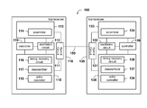
- FIG. 1 shows a simplified block diagram of an example communication system 100 , arranged in accordance with at least some embodiments of the present disclosure.
- the communication system 100 comprises a transceiver 110 , a transceiver 130 , and transmission lines 150 .
- the communication system 100 is an HDMI compatible system.
- the transceivers 110 and 130 are HEC transceivers of the HDMI transceiving devices and the transmission lines 150 are used for carrying the HEC signals and/or other signals in the HDMI cable.
- the transmission lines 150 are a pair of conductors for carrying differential signals. In another embodiment, the transmission lines 150 are used for carrying single-ended signals.
- the transmission lines 150 may be realized with Cat-3 ⁇ Cat-7 twisted pair cables, wirings on the printed circuit board, or other suitable conductors.
- the transceiver 110 comprises a hybrid circuit 111 , an oscillation circuit 112 , a transmitter 113 , a receiver 115 , and a controller 119 .
- the transmitter 113 comprises a scrambler 114 .
- the receiver 115 comprises a timing recovery circuit 116 , a descrambler 117 , and an echo canceller 118 .
- the transceiver 130 comprises a hybrid circuit 131 , an oscillation circuit 132 , a transmitter 133 , a receiver 135 , and a controller 139 .
- the transmitter 133 comprises a scrambler 134 .
- the receiver 135 comprises a timing recovery circuit 136 , a descrambler 137 , and an echo canceller 138 .
- Other components, circuits, and connections are omitted in FIG. 1 for conciseness.
- the transmitter 113 of the transceiver 110 transmits signals to the transmission lines 150 through the hybrid circuit 111 .
- the receiver 115 also receives the signals on the transmission lines 150 through the hybrid circuit 111 . Because the transmission lines 150 carry the signals from the transmitter 113 of the transceiver 110 and the signals from the transmitter 133 of the transceiver 130 , the receiver 115 may remove the signals from the transmitter 113 from the received signals by using the echo canceller 118 .
- the scrambler 114 of the transmitter 110 is used for scrambling the signals before signal transmission.
- the descrambler 117 is used for descrambling the received scrambled signals and generating the unscrambled signals.
- the architecture and operation of the scrambler 114 and the descrambler 117 are further described below accompanied with FIG. 2 .
- the scrambler 114 of the transceiver 110 and the descrambler 134 of the transceiver 130 have the same generator polynomial.
- the timing recovery circuit 116 is used for adjusting the timing for transmitting signals and/or receiving signals.
- the timing recovery circuit 116 may provide the phase compensation and/or the frequency compensation so that the analog-to-digital converter (not shown in FIG. 1 ) of the receiver 115 may sample the signals at the moderate time.
- the receiver 115 receives the signals transmitted by the transceiver 130 from the transmission lines 150 .
- the timing recovery circuit 116 may estimate the frequency of the transceiver 130 , i.e., the frequency of the oscillating signal generated by the oscillation circuit 132 of the transceiver 130 , according to the signals received by the receiver 115 .
- the controller 119 is used to configure the transmitter 113 , the receiver 114 , and/or other components so that the transceiver 110 may transmit and receive signals correctly. For example, in the idle mode or in the connection establishment process, when the transceivers 110 and 130 transmit the same signal, the transceiver 110 and/or the transceiver 130 may not function correctly. Ideally, the input of the descrambler 117 and the output of the scrambler 134 have the same data. To avoid the malfunction of the transceiver 110 , the controller 119 may monitor the output of the scrambler 114 , the input of the descrambler 117 , the registers of the scrambler 114 , and/or the registers of the descrambler 117 . The controller 119 may therefore detect whether the transceivers 110 and 130 transmit the same signals and configure relevant components correspondingly. The function of the controller 119 is explained in more details below.
- transceiver 130 The function and the connection of the components in the transceiver 130 are similar to the counterparts in the transceiver 110 , and may be referred to the relevant descriptions above.
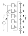
- FIG. 2 shows a simplified block diagram of an example scrambler/descrambler 200 , arranged in accordance with at least some embodiments of the present disclosure.
- the scrambler/descrambler 200 in FIG. 2 is realized with the scrambler/descrambler architecture of the fast Ethernet 100BASE-TX transceiver.
- the scrambler/descrambler 200 may be used as a scrambler or a descrambler depending on the input data.
- the scrambler/descrambler 200 functions as a scrambler and outputs scrambled data Dout.
- the scrambler/descrambler 200 functions as a descrambler and outputs unscrambled data Dout.
- the scrambler/descrambler 200 comprises eleven shift registers 210 ⁇ 211 , and two XOR (exclusive or) circuits 220 and 230 .
- the operation of the scrambler/descrambler 200 is described as follows. At time T, the input data Din(T) and the values of the shift registers 209 and 211 are processed by the XOR circuits 220 and 230 , and output as the output Dout(T) of the scrambler/descrambler 200 .
- the values stored in the shift registers 201 ⁇ 210 at time T are stored in the shift register 202 ⁇ 211 , respectively.
- the value stored in shift register 203 at time T is stored in the shift register 204 at time T+1.
- the values stored in the shift registers 209 and 211 at time T are processed by the XOR circuit 220 and stored in the shift register 201 at time T+1.
- the input data Din(T+1) and the values of the shift registers 209 and 211 are processed by the XOR circuits 220 and 230 and output as the output Dout(T+1) of the scrambler/descrambler 200 .
- the transceiver 110 is configured to transmit idle signals in the idle mode or in the connection establishment process.
- the transceiver 110 configures the input data Din to be the value “1” and configures the values of the shift registers 201 ⁇ 211 not to be all zeros.
- the values of the shift registers 201 ⁇ 211 have 2047 possible combinations, i.e., 2 11 -1 (except the all zeros situation), which cyclically appear. Accordingly, the output Dout of the scrambler/descrambler 200 has 2047 cyclically appeared values, a.k.a. the idle sequence.
- each of the 2047 cyclically appeared combinations of the values of the shift registers 201 ⁇ 211 is serially assigned to a unique number.
- the combination number is assigned as 1.
- the combination number is assigned as 2.
- the combination number is assigned as 2047.
- another combination of the values of the shift registers 201 ⁇ 211 is assigned as the combination number 1 and the other combinations of the values of the shift registers 201 ⁇ 211 are respectively assigned to unique combination numbers according the operation of the scrambler/descrambler 200 or in other suitable order.
- the combination number of the values of the shift registers 201 ⁇ 211 of the scrambler 114 is N, for the purpose of simplicity, it is referred that the combination number of the scrambler 114 is N.
- the combination number difference between the scrambler 114 and the descrambler 117 is defined as the absolute value of (M ⁇ N).
- the 2047 possible values are stored in the transceiver 110 .
- the controller 119 compares the values of the shift registers of the scrambler 114 with the values of the 2047 combinations to obtain the combination number of the scrambler 114 .
- the transceiver 110 only stores the values [11111111111].
- the controller 119 calculates the processing time, the iteration number, the number of input bit(s) of the scrambler 114 , and/or the number of output bit(s) of the scrambler 114 before the values of the shift registers of the scrambler 114 become [11111111111].
- the controller 119 may directly use or process the calculated data above to obtain the combination number of the scramble 114 .
- the 2047-bit cyclically appeared output data of the scrambler 114 corresponding to the combination numbers 1 ⁇ 2047 are stored in the transceiver 110 .
- the controller 119 compares the output of the scrambler 114 with the 2047-bit idle sequence to obtain the combination number of the scrambler 114 . For example, after comparing 11 bits output of the scrambler 114 with the 2047-bit idle sequence, the controller 119 finds the 11 bits output matches the 21 st ⁇ 31 st bits of the 2047 idle sequence and determines the combination number of the scrambler 114 to be 31.
- the transceiver 110 only stores the values [01111111111].
- the controller 119 calculates the processing time, the iteration number, the number of input bit(s) of the scrambler 114 , and/or the number of output bit(s) of the scrambler 114 before the output of the scrambler 114 become [01111111111].
- the controller 119 may directly use or process the calculated data above to obtain the combination number of the scramble 114 .
- the transceiver 110 may store the combination number of the scrambler 114 in the storage device.
- the content of the storage device may be updated accordingly and the calculation of the combination number of the scrambler 114 may be reduced or omitted.
- the controller 119 may also adopt the above methods to obtain the combination number of the descrambler 117 .
- the controller 119 may adopt the same or different method(s) to obtain the combination number of the scrambler 114 and the combination number of the descrambler 117 .
- the combination number difference is needed.
- the controller 119 may calculate the processing time, the iteration number, the number of input bit(s) of the scrambler 114 , and/or the number of output bit(s) of the scrambler 114 before the values of the shift registers of the scrambler 114 become the values of the shift registers of the descrambler 117 .
- the controller 119 may directly use or process the calculated data above to obtain the combination number difference of the scrambler 114 and the descrambler 117 .
- the controller 119 may calculate the processing time, the iteration number, the number of input bit(s) of the scrambler 114 , and/or the number of output bit(s) of the scrambler 114 before the output data of the scrambler 114 become the output data of the descrambler 117 .
- the controller 119 may directly use or process the calculated data above to obtain the combination number difference of the scrambler 114 and the descrambler 117 .
- the transceivers 110 and 130 and the scrambler/descrambler 200 may be realized with controller(s), processor(s), specifically designed integrated/discrete circuit(s), and/or the collaboration of hardware and software.
- the components and the connections are illustrative only. Multiple functional blocks may be realized with a single component and a single functional block may be realized with multiple components.
- the architecture of each functional block may also be modified according to different design considerations.
- the transceivers may be realized with scramblers, transmitters, and/or receivers of different architectures.
- the transceivers 110 and 130 start to establish the connection.
- the transmitters 113 and 133 of the transceivers 110 and 130 both trans-mit idle signals.
- the controller 119 determines whether the transceiver 110 shall enter the slave mode according to various criterions. If the controller 119 configures the transceiver 110 to enter the slave mode, the method proceeds to the operation 330 . Otherwise, the method proceeds to the operation 360 .
- the controller 119 determines whether the transceiver 110 shall enter the slave mode according to the output of the scrambler 114 , the values of the shift registers of the scrambler 114 , the combination number of the scrambler 114 , the input of the descrambler 117 , the values of the shift registers of the descrambler 117 , the combination number of the descrambler 117 , and/or the computation result of the data above.
- the transceiver 110 enters the slave mode.
- the controller 119 calculates the combination number difference of the scrambler 114 and the descrambler 117 .
- the method proceeds to the operation 350 . Otherwise, the method proceeds to the operation 340 .
- the predetermined ranged is configured as half of the possible the combination numbers of the values of the shift registers of the scrambler 114 plus/minus the suitable value(s).
- the predetermined range may be configured as (1024-10) ⁇ (1024+10).
- the predetermined ranged is configured as half of the possible the combination numbers of the values of the shift registers of the scrambler 114 .
- the controller 119 configures the combination number difference of the scrambler 114 and the descrambler 117 to locate in the predetermined range or equal to the predetermined value so that the combination number difference of the scrambler 114 and the descrambler 117 may be enlarged.
- the scramblers 114 and 134 generate the same signals and therefore the transceivers 110 and 130 fail to function correctly.
- the controller 119 configures the oscillation circuit 112 to generate the oscillating signal, the frequency of which is different from the frequency of the oscillating signal generated by the oscillation circuit 132 by a frequency difference.
- the combination number difference of the scramblers 114 and 134 may be changed gradually. That is, the combination number difference of the scrambler 114 and the descrambler 117 may be changed gradually so that the combination number difference of the scrambler 114 and the descrambler 117 may locate in the predetermined range or equal to the predetermined value.
- the method may proceed to the operation 330 so as to determine whether the combination number difference locates in the predetermined range or equals to the predetermined value.
- the controller 119 configures the oscillation circuit 112 to generate the oscillating signal of a fixed frequency so that the far-end transceiver 130 may follow the frequency of the oscillating signal generated by the oscillation circuit 112 .
- the connection between the transceivers 110 and 130 are established.
- the timing recovery circuit 340 and the controller 119 are used in the operations 340 and 350 to process the received signals and estimate the frequency of the oscillating signal generated by the oscillation circuit 132 .
- control 119 configures the predetermined range or the predetermined value in the operation 330 .
- the method proceeds to the operation 340 . Otherwise, the method proceeds to the operation 350 .
- the controller 119 configures the frequency of the oscillating signal generated by the oscillation circuit 112 so as to change the combination number difference of the scrambler 114 and the descrambler 117 .
- the controller 119 configures the oscillation circuit 112 to adjust the frequency of the oscillating signal.
- the combination number of the scrambler 114 is N
- the combination number of the descrambler 117 is M
- the combination number difference of the scrambler 114 and the descrambler 117 is defined as the absolute value of (M ⁇ N) and ranges between 0 ⁇ 2046.
- the frequency of the oscillating signal generated by the oscillation circuit 132 is 125 MHz.
- the controller 119 may configure the frequency of the oscillating signal generated by the oscillation circuit 132 to be 125 MHz-1 ppm ⁇ 125 MHz. Thus, the combination number difference of the scrambler 114 and the descrambler 117 may be gradually adjusted from 2000 to the predetermined value 1024.
- the frequency difference between the oscillating signals generated by the oscillation circuits 112 and 132 is 1 ppm.
- the controller 119 may configure the frequency of the oscillating signal generated by the oscillation circuit 132 to be 125 MHz+1 ppm ⁇ 125 MHz.
- the combination number difference of the scrambler 114 and the descrambler 117 may be gradually adjusted from 2000 to the predetermined value 1024.
- the controller 119 may also choose other suitable values of frequency difference for adjusting the combination number difference.
- the predetermined range is configured as half of the possible the combination numbers of the values of the shift registers of the scrambler 114 plus/minus the suitable value(s). In another embodiment of the operation 420 , the predetermined range is configured as half of the possible the combination numbers of the values of the shift registers of the scrambler 114 .
- the controller 119 In the operation 430 , the controller 119 generates an adjustment value according to the combination number difference of the scrambler 114 and the descrambler 117 and the predetermined range/value. According to the adjustment value, the controller 119 configures the values of the shift registers of the scrambler 114 to be the values of the registers of another combination number. The adjusted combination number difference of the scrambler 114 and the descrambler 117 may therefore be closer to the predetermined range/value. After the controller 119 adjusts the values of the shift registers of the scrambler 114 , the method proceeds to the operation 440 .
- the transmitter 130 of the transceiver 110 transmits the signal(s) indicating the transceiver 110 enters the power saving mode. Then, the transceiver 110 enters the power saving mode.
- the controller 119 may configure the adjustment value to be half of the difference between a reference value and the combination number difference of the scrambler 114 and the descrambler 117 .
- the controller 119 may configure the values of the registers of the scrambler 114 to be the values of the shift registers of the combination number 688, i.e., the combination number of the scrambler 114 (1100) minus the adjustment value (412).
- the adjusted combination number difference is therefore 612, which is closer to the predetermined difference value 1024 than the original combination number difference 200.
- the embodiments in FIGS. 1-4 may be separately or collaboratively implemented.
- the transceivers 110 and 130 may adopt the same or different method(s) to establish the connection.
- the network connection may be sustained more stably.
- the method(s) may be applied in the conventional devices and compatible with the existing industry standard and therefore the transceivers 110 or 130 possess very high compatibility.
- the controller 119 may adjust the frequency of the oscillating signal generated by the oscillation circuit 112 in the connection establishing process.
- the combination number difference of the scramblers 114 and 134 may be enlarged so that the transceivers 110 and 130 do not fail to function due to transmitting the same signals.
- the controller 119 may adjust the frequency of the oscillating signal generated by the oscillation circuit 112 before the transmitter 130 enters the power saving mode.
- the combination number difference of the scramblers 114 and 134 may be enlarged so that the transceivers 110 and 130 do not fail to function due to transmitting the same signals after leaving the power saving mode.
- the present disclosure may be applicable to the communication systems, in which the transceivers on both ends may transmit the same signals on the same transmission lines at the same time. Therefore, the communication systems may maintain connection more stably.
Landscapes
- Engineering & Computer Science (AREA)
- Computer Networks & Wireless Communication (AREA)
- Signal Processing (AREA)
- Synchronisation In Digital Transmission Systems (AREA)
- Small-Scale Networks (AREA)
- Mobile Radio Communication Systems (AREA)
Abstract
Description
- This application claims the benefit of priority to Taiwanese Patent Application No. 099146244, filed on Dec. 28, 2010; the entirety of which is incorporated herein by reference for all purposes.
- The present disclosure generally relates to communication devices and methods and, more particularly, to the full duplex communication device with the energy saving mode and the communication method thereof.
- Nowadays, many electronic devices adopt the energy saving mechanism for utilizing the power more wisely, extending the battery usage time of the portable devices, and therefore achieving better environmental protection. For example, the Energy Efficient Ethernet (EEE) standard, developed by the IEEE 802.3az task force, defines several mechanisms for reducing the power consumption. During the periods of low data activity, the EEE-compatible transceivers may enter the power saving mode (a.k.a., the quiet mode, the sleep mode, the energy saving mode, etc.) and stop sending idle signals. The energy for sending idle signals in the power saving mode may therefore be saved.
- In the High-Definition Multimedia Interface (HDMI), the fast Ethernet technology, i.e., 100BASE-TX of the IEEE 802.3u standard, is used in the HDMI Ethernet Channel (HEC) communication. Conventional 100BASE-TX transceivers may be modified to be compatible with the EEE standard with some changes. The HEC transceivers, although using the similar technology with 100 BASE-TX transceivers, may not be compatible with the EEE standard for several reasons.
- For example, although both the 100BASE-TX transceivers and the HEC transceivers may operate in the full duplex mode, the 100BASE-TX transceiver trans-mits signals on one twisted pair of conductors and receives signals on another twisted pair of conductors. On the other hand, the HEC transceiver may transmit and receive signals on the same twisted pair of conductors simultaneously. When the near-end HEC transceiver receives the signals transmitted from the far-end HEC transceiver, the near-end HEC transceiver therefore may also receive the signals transmitted by itself. When the near-end HEC transceiver and the far-end HEC transceiver transmit the same signals, both HEC transceivers may not differentiate the near-end signals and the far-end signals and therefore fail to function correctly.
- Besides, in the idle mode or in the connection establishment process, the HEC transceivers on both ends need to transmit idle signals. The HEC transceivers continuously and repeatedly transmit the pseudo random code of several thousand bits as the idle signals. The HDMI standard does not adopt the master-slave mechanism and does not require the near-end and the far-end HEC transceivers to use different scramblers. Thus, in the idle mode or in the connection establishment process, the near-end and the far-end HEC transceivers may transmit the same idle signals and therefore fail to function correctly.
- Moreover, although the HEC transceivers shall transmit the signals with a 125 MHz frequency, there still may be a difference existed between the transmission frequencies of the transceivers on both ends. For example, a difference with ±200 ppm of the transmission frequency is tolerable in some technical standards. Therefore, even if the near-end and the far-end HEC transceivers are configured to transmit the idle signals from different positions of the same pseudo random code, the difference between the transmission frequencies may still cause the near-end and the far-end HEC transceivers to transmit the same idle signals after a period of time. The HEC transceivers may still fail to function correctly in this configuration.
- Furthermore, if the HEC transceivers are to support the EEE function, the HEC transceivers shall avoid transmitting the same idle signals after leaving the power saving mode, which may cause the malfunction of the HEC transceivers.
- In view of the foregoing, it can be appreciated that a substantial need exists for methods and apparatuses that can mitigate or reduce the problems in the communication process.
- An example embodiment of a communication device, comprising: a transmitter, for transmitting to a transmission line a first data generated by a first scrambler with a plurality of first registers characterized by a first combination number; a receiver, for receiving from the transmission line a second data generated by a second scrambler, comprising a descrambler for descrambling the second data with a plurality of second registers characterized by a second combination number; and a controller, coupled to the transmitter and the receiver, for adjusting the values of the first registers according to the first combination number, the second combination number, and/or a first combination number difference between the first combination number and the second combination number; wherein the first scrambler and the second scrambler have the same scrambler generator polynomial.
- Another example embodiment of a communication device, comprising: a transmitter, for transmitting to a transmission line a first data generated by a first scrambler with a plurality of first registers characterized by a first combination number according to a oscillating signal generated by an oscillation circuit; a receiver, for receiving from the transmission line a second data generated by a second scrambler of a transceiver, comprising a descrambler for descrambling the second data with a plurality of second registers characterized by a second combination number; and a controller, coupled to the transmitter and the receiver, for configuring the oscillation circuit for adjusting the frequency of the oscillating signal so that a frequency difference existed between the frequency of the oscillating signal and a transmission frequency of the transceiver when a combination number difference between the first combination number and the second combination number locates in a predetermined range and/or equals to a predetermined value; wherein the first scrambler and the second scrambler have the same scrambler generator polynomial.
- An example embodiment of a communication method, comprising: transmitting to a transmission line a first data generated by a first scrambler with a plurality of first registers characterized by a first combination number; receiving from the transmission line a second data generated by a second scrambler; descrambling the second data with a descrambler with a plurality of second registers characterized by a second combination number; and adjusting the values of the first registers according to the first combination number, the second combination number, and/or a first combination number difference between the first combination number and the second combination number.
- An example embodiment of a communication method, comprising: transmitting to a transmission line a first data generated by a first scrambler with a plurality of first registers characterized by a first combination number according to a oscillating signal generated by an oscillation circuit; receiving from the transmission line a second data generated by a second scrambler of a transceiver; descrambling the second data with a descrambler with a plurality of second registers characterized by a second combination number; and configuring the oscillation circuit for adjusting the frequency of the oscillating signal so that a frequency difference existed between the frequency of the oscillating signal and a transmission frequency of the transceiver when a combination number difference between the first combination number and the second combination number locates in a predetermined range and/or equals to a predetermined value.
- It is to be understood that both the foregoing general description and the following detailed description are example and explanatory only and are not restrictive of the disclosure, as claimed.
-
FIG. 1 is a simplified block diagram of an example communication system; -
FIG. 2 is a simplified block diagram of an example scrambler/descrambler inFIG. 1 ; -
FIG. 3 is a simplified flowchart of an example connection establishing method; and -
FIG. 4 is a simplified flowchart of an example power saving mode control method, all arranged in accordance with at least some embodiments of the present disclosure described herein. - Reference will now be made in detail to embodiments of the disclosure, which are illustrated in the accompanying drawings. The same reference numbers may be used throughout the drawings to refer to the same or like parts or components/operations. Certain terms are used throughout the description and the claims to refer to particular components. As one skilled in the art will appreciate, a component may be referred by different names. This document does not intend to distinguish between components that differ in name but not in function. In the following description and in the claims, the terms “comprise” are used in an open-ended fashion, and thus should be interpreted to mean “include, but not limited to . . . . ” The phrase “coupled with” is intended to compass any indirect or direct connection. Accordingly, if this document mentioned that a first device is coupled with a second device, it means that the first device may be directly or indirectly connected to the second device through electrical connections, wireless communications, optical communications, or other signal connections with/without other intermediate devices or connection means.
-
FIG. 1 shows a simplified block diagram of anexample communication system 100, arranged in accordance with at least some embodiments of the present disclosure. Thecommunication system 100 comprises atransceiver 110, atransceiver 130, andtransmission lines 150. For example, thecommunication system 100 is an HDMI compatible system. Thetransceivers transmission lines 150 are used for carrying the HEC signals and/or other signals in the HDMI cable. - In this embodiment, the
transmission lines 150 are a pair of conductors for carrying differential signals. In another embodiment, thetransmission lines 150 are used for carrying single-ended signals. For example, thetransmission lines 150 may be realized with Cat-3˜Cat-7 twisted pair cables, wirings on the printed circuit board, or other suitable conductors. - The
transceiver 110 comprises ahybrid circuit 111, anoscillation circuit 112, atransmitter 113, areceiver 115, and acontroller 119. Thetransmitter 113 comprises ascrambler 114. Thereceiver 115 comprises atiming recovery circuit 116, adescrambler 117, and anecho canceller 118. Thetransceiver 130 comprises ahybrid circuit 131, anoscillation circuit 132, atransmitter 133, areceiver 135, and acontroller 139. Thetransmitter 133 comprises ascrambler 134. Thereceiver 135 comprises atiming recovery circuit 136, adescrambler 137, and anecho canceller 138. Other components, circuits, and connections are omitted inFIG. 1 for conciseness. - In this embodiment, the
transmitter 113 of thetransceiver 110 transmits signals to thetransmission lines 150 through thehybrid circuit 111. Thereceiver 115 also receives the signals on thetransmission lines 150 through thehybrid circuit 111. Because thetransmission lines 150 carry the signals from thetransmitter 113 of thetransceiver 110 and the signals from thetransmitter 133 of thetransceiver 130, thereceiver 115 may remove the signals from thetransmitter 113 from the received signals by using theecho canceller 118. - The
oscillation circuit 112 is used for generating the oscillating signal with a suitable frequency so that thetransmitter 113, thereceiver 115, and other components of thetransceiver 110 may transmit or receive signals according to the oscillating signal. For example, when thetransceivers transceivers transceivers oscillation circuit 112 and/or theoscillation circuit 132 may be configured to adjust the frequency of the oscillating signal. Thus, the frequencies of thetransceivers transceivers - The
scrambler 114 of thetransmitter 110 is used for scrambling the signals before signal transmission. Thedescrambler 117 is used for descrambling the received scrambled signals and generating the unscrambled signals. The architecture and operation of thescrambler 114 and thedescrambler 117 are further described below accompanied withFIG. 2 . Moreover, in this embodiment, thescrambler 114 of thetransceiver 110 and thedescrambler 134 of thetransceiver 130 have the same generator polynomial. - The
timing recovery circuit 116 is used for adjusting the timing for transmitting signals and/or receiving signals. For example, thetiming recovery circuit 116 may provide the phase compensation and/or the frequency compensation so that the analog-to-digital converter (not shown inFIG. 1 ) of thereceiver 115 may sample the signals at the moderate time. In one embodiment, thereceiver 115 receives the signals transmitted by thetransceiver 130 from thetransmission lines 150. Thetiming recovery circuit 116 may estimate the frequency of thetransceiver 130, i.e., the frequency of the oscillating signal generated by theoscillation circuit 132 of thetransceiver 130, according to the signals received by thereceiver 115. - The
controller 119 is used to configure thetransmitter 113, thereceiver 114, and/or other components so that thetransceiver 110 may transmit and receive signals correctly. For example, in the idle mode or in the connection establishment process, when thetransceivers transceiver 110 and/or thetransceiver 130 may not function correctly. Ideally, the input of thedescrambler 117 and the output of thescrambler 134 have the same data. To avoid the malfunction of thetransceiver 110, thecontroller 119 may monitor the output of thescrambler 114, the input of thedescrambler 117, the registers of thescrambler 114, and/or the registers of thedescrambler 117. Thecontroller 119 may therefore detect whether thetransceivers controller 119 is explained in more details below. - The function and the connection of the components in the
transceiver 130 are similar to the counterparts in thetransceiver 110, and may be referred to the relevant descriptions above. - The operation of the
communication system 100 is further explained below accompanied withFIGS. 1 and 2 .FIG. 2 shows a simplified block diagram of an example scrambler/descrambler 200, arranged in accordance with at least some embodiments of the present disclosure. - The scrambler/
descrambler 200 inFIG. 2 is realized with the scrambler/descrambler architecture of the fast Ethernet 100BASE-TX transceiver. The scrambler/descrambler 200 may be used as a scrambler or a descrambler depending on the input data. When the input data Din are unscrambled data, the scrambler/descrambler 200 functions as a scrambler and outputs scrambled data Dout. When the input data Din are scrambled data, the scrambler/descrambler 200 functions as a descrambler and outputs unscrambled data Dout. - The scrambler/
descrambler 200 comprises elevenshift registers 210˜211, and two XOR (exclusive or)circuits - The operation of the scrambler/
descrambler 200 is described as follows. At time T, the input data Din(T) and the values of the shift registers 209 and 211 are processed by theXOR circuits descrambler 200. - At time T+1, the values stored in the
shift registers 201˜210 at time T are stored in theshift register 202˜211, respectively. For example, the value stored inshift register 203 at time T is stored in theshift register 204 at time T+1. The values stored in the shift registers 209 and 211 at time T are processed by theXOR circuit 220 and stored in theshift register 201 at time T+1. The input data Din(T+1) and the values of the shift registers 209 and 211 are processed by theXOR circuits descrambler 200. - In this embodiment, the
transceiver 110 is configured to transmit idle signals in the idle mode or in the connection establishment process. Thetransceiver 110 configures the input data Din to be the value “1” and configures the values of theshift registers 201˜211 not to be all zeros. The values of theshift registers 201˜211 have 2047 possible combinations, i.e., 211-1 (except the all zeros situation), which cyclically appear. Accordingly, the output Dout of the scrambler/descrambler 200 has 2047 cyclically appeared values, a.k.a. the idle sequence. - In this embodiment, each of the 2047 cyclically appeared combinations of the values of the
shift registers 201˜211 is serially assigned to a unique number. For example, according to the operation of the scrambler/descrambler 200, when the values of theshift registers 201˜211 are [111111111111], the combination number is assigned as 1. When the values of theshift registers 201˜211 are [011111111111], the combination number is assigned as 2. By using this rule, when the values of theshift registers 201˜211 are [111111111110], the combination number is assigned as 2047. In another embodiment, another combination of the values of theshift registers 201˜211 is assigned as the combination number 1 and the other combinations of the values of theshift registers 201˜211 are respectively assigned to unique combination numbers according the operation of the scrambler/descrambler 200 or in other suitable order. - In the specification and the claims, when the combination number of the values of the
shift registers 201˜211 of thescrambler 114 is N, for the purpose of simplicity, it is referred that the combination number of thescrambler 114 is N. When the combination number of thescrambler 114 is N and the combination number of thedescrambler 117 is M, the combination number difference between thescrambler 114 and thedescrambler 117 is defined as the absolute value of (M−N). - In other embodiments, the combination number difference between the
scrambler 114 and thedescrambler 117 may also be defined as (N−M), (M−N), or (M−N) when M>=N and (M−N+2047) when M<N. - In another embodiment, the 2047 possible values are stored in the
transceiver 110. Thecontroller 119 compares the values of the shift registers of thescrambler 114 with the values of the 2047 combinations to obtain the combination number of thescrambler 114. - In another embodiment, only parts of the values of the 2047 combinations are stored in the
transceiver 110. For example, thetransceiver 110 only stores the values [11111111111]. Thecontroller 119 calculates the processing time, the iteration number, the number of input bit(s) of thescrambler 114, and/or the number of output bit(s) of thescrambler 114 before the values of the shift registers of thescrambler 114 become [11111111111]. Thecontroller 119 may directly use or process the calculated data above to obtain the combination number of thescramble 114. - In another embodiment, the 2047-bit cyclically appeared output data of the
scrambler 114 corresponding to the combination numbers 1˜2047 (i.e., the 2047-bit idle sequence) are stored in thetransceiver 110. Thecontroller 119 compares the output of thescrambler 114 with the 2047-bit idle sequence to obtain the combination number of thescrambler 114. For example, after comparing 11 bits output of thescrambler 114 with the 2047-bit idle sequence, thecontroller 119 finds the 11 bits output matches the 21st˜31st bits of the 2047 idle sequence and determines the combination number of thescrambler 114 to be 31. - In another embodiment, only parts of the 2047-bit cyclically appeared output data of the
scrambler 114 corresponding to the combination numbers 1˜2047 are stored in thetransceiver 110. For example, thetransceiver 110 only stores the values [01111111111]. Thecontroller 119 calculates the processing time, the iteration number, the number of input bit(s) of thescrambler 114, and/or the number of output bit(s) of thescrambler 114 before the output of thescrambler 114 become [01111111111]. Thecontroller 119 may directly use or process the calculated data above to obtain the combination number of thescramble 114. - In another embodiment, the
transceiver 110 may store the combination number of thescrambler 114 in the storage device. The content of the storage device may be updated accordingly and the calculation of the combination number of thescrambler 114 may be reduced or omitted. - The
controller 119 may also adopt the above methods to obtain the combination number of thedescrambler 117. Thecontroller 119 may adopt the same or different method(s) to obtain the combination number of thescrambler 114 and the combination number of thedescrambler 117. - In another embodiment, the combination number difference is needed. The
controller 119 may calculate the processing time, the iteration number, the number of input bit(s) of thescrambler 114, and/or the number of output bit(s) of thescrambler 114 before the values of the shift registers of thescrambler 114 become the values of the shift registers of thedescrambler 117. Thecontroller 119 may directly use or process the calculated data above to obtain the combination number difference of thescrambler 114 and thedescrambler 117. - In another embodiment, the
controller 119 may calculate the processing time, the iteration number, the number of input bit(s) of thescrambler 114, and/or the number of output bit(s) of thescrambler 114 before the output data of thescrambler 114 become the output data of thedescrambler 117. Thecontroller 119 may directly use or process the calculated data above to obtain the combination number difference of thescrambler 114 and thedescrambler 117. - In the embodiments in
FIGS. 1 and 2 , thetransceivers descrambler 200 may be realized with controller(s), processor(s), specifically designed integrated/discrete circuit(s), and/or the collaboration of hardware and software. The components and the connections are illustrative only. Multiple functional blocks may be realized with a single component and a single functional block may be realized with multiple components. The architecture of each functional block may also be modified according to different design considerations. For example, the transceivers may be realized with scramblers, transmitters, and/or receivers of different architectures. - The operation of the
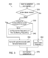
communication system 100 is further explained below accompanied withFIGS. 1-3 .FIG. 3 shows a simplified flowchart of an exampleconnection establishing method 300, arranged in accordance with at least some embodiments of the present disclosure. - In the
operation 310, thetransceivers transmitters transceivers - In the
operation 320, thecontroller 119 determines whether thetransceiver 110 shall enter the slave mode according to various criterions. If thecontroller 119 configures thetransceiver 110 to enter the slave mode, the method proceeds to theoperation 330. Otherwise, the method proceeds to theoperation 360. - In one embodiment of the
operation 320, thecontroller 119 determines whether thetransceiver 110 shall enter the slave mode according to the output of thescrambler 114, the values of the shift registers of thescrambler 114, the combination number of thescrambler 114, the input of thedescrambler 117, the values of the shift registers of thedescrambler 117, the combination number of thedescrambler 117, and/or the computation result of the data above. - In the
operation 330, thetransceiver 110 enters the slave mode. Thecontroller 119 calculates the combination number difference of thescrambler 114 and thedescrambler 117. When the combination number difference of thescrambler 114 and thedescrambler 117 locates in a predetermined range or equals to a predetermined value, the method proceeds to theoperation 350. Otherwise, the method proceeds to theoperation 340. - In one embodiment of the
operation 330, the predetermined ranged is configured as half of the possible the combination numbers of the values of the shift registers of thescrambler 114 plus/minus the suitable value(s). For example, when the scrambler/descrambler 200 is adopted, the predetermined range may be configured as (1024-10)˜(1024+10). In another embodiment of theoperation 330, the predetermined ranged is configured as half of the possible the combination numbers of the values of the shift registers of thescrambler 114. - In the above two embodiments, the
controller 119 configures the combination number difference of thescrambler 114 and thedescrambler 117 to locate in the predetermined range or equal to the predetermined value so that the combination number difference of thescrambler 114 and thedescrambler 117 may be enlarged. Thus, it is less likely that thescramblers transceivers - In the
operation 340, thecontroller 119 configures theoscillation circuit 112 to generate the oscillating signal, the frequency of which is different from the frequency of the oscillating signal generated by theoscillation circuit 132 by a frequency difference. By configuring the frequency difference between the oscillating signals generated by theoscillation circuits scramblers scrambler 114 and thedescrambler 117 may be changed gradually so that the combination number difference of thescrambler 114 and thedescrambler 117 may locate in the predetermined range or equal to the predetermined value. Moreover, after a period of time and/or after transmitting certain number of bits, the method may proceed to theoperation 330 so as to determine whether the combination number difference locates in the predetermined range or equals to the predetermined value. - In the
operation 350, thecontroller 119 configures theoscillation circuit 112 to generate the oscillating signal, which follows the frequency of the oscillating signal generated by theoscillation circuit 132. The frequencies of the oscillating signals generated by theoscillation circuits transceivers - In the
operation 360, thecontroller 119 configures theoscillation circuit 112 to generate the oscillating signal of a fixed frequency so that the far-end transceiver 130 may follow the frequency of the oscillating signal generated by theoscillation circuit 112. - In the
operation 370, the connection between thetransceivers - In the description above, the
method 300 is explained in the aspect of thetransceiver 110. Themethod 300 may also be applied to thetransceiver 130 to establish the connection between thetransceivers - In one embodiment, the
timing recovery circuit 340 and thecontroller 119 are used in theoperations oscillation circuit 132. - In another embodiment, the
control 119 configures the predetermined range or the predetermined value in theoperation 330. When the combination number difference of thescrambler 114 and thedescrambler 117 locates in the predetermined range or equal to the predetermined value, the method proceeds to theoperation 340. Otherwise, the method proceeds to theoperation 350. For example, when the combination number difference of thescrambler 114 and thedescrambler 117 locates between 0˜1023 or between 1025˜2046, the method proceeds to theoperation 340. Thecontroller 119 configures the frequency of the oscillating signal generated by theoscillation circuit 112 so as to change the combination number difference of thescrambler 114 and thedescrambler 117. - In another embodiment of the
operation 340, thecontroller 119 configures theoscillation circuit 112 to adjust the frequency of the oscillating signal. For example, the combination number of thescrambler 114 is N, and the combination number of thedescrambler 117 is M. The combination number difference of thescrambler 114 and thedescrambler 117 is defined as the absolute value of (M−N) and ranges between 0˜2046. The frequency of the oscillating signal generated by theoscillation circuit 132 is 125 MHz. When the combination number difference of thescrambler 114 and thedescrambler 117 is 2000 and the predetermined value is 1024, thecontroller 119 may configure the frequency of the oscillating signal generated by theoscillation circuit 132 to be 125 MHz-1 ppm×125 MHz. Thus, the combination number difference of thescrambler 114 and thedescrambler 117 may be gradually adjusted from 2000 to the predetermined value 1024. In this embodiment, the frequency difference between the oscillating signals generated by theoscillation circuits controller 119 may configure the frequency of the oscillating signal generated by theoscillation circuit 132 to be 125 MHz+1 ppm×125 MHz. Thus, the combination number difference of thescrambler 114 and thedescrambler 117 may be gradually adjusted from 2000 to the predetermined value 1024. Thecontroller 119 may also choose other suitable values of frequency difference for adjusting the combination number difference. - The operation of the
communication system 100 is further explained below accompanied withFIGS. 1 , 2, and 4.FIG. 4 shows a simplified flowchart of an example power savingmode control method 400, arranged in accordance with at least some embodiments of the present disclosure. - In the
operation 410, thetransmitter 113 of thetransceiver 110 is ready to enter the power saving mode. - In the
operation 420, thecontroller 119 calculates the combination number difference of thescrambler 114 and thedescrambler 117. When the combination number difference of thescrambler 114 and thedescrambler 117 locates in the predetermined range or equals to the predetermined value, the method proceeds to theoperation 440. Otherwise, the method proceeds to theoperation 430. - In one embodiment of the
operation 420, the predetermined range is configured as half of the possible the combination numbers of the values of the shift registers of thescrambler 114 plus/minus the suitable value(s). In another embodiment of theoperation 420, the predetermined range is configured as half of the possible the combination numbers of the values of the shift registers of thescrambler 114. - In the
operation 430, thecontroller 119 generates an adjustment value according to the combination number difference of thescrambler 114 and thedescrambler 117 and the predetermined range/value. According to the adjustment value, thecontroller 119 configures the values of the shift registers of thescrambler 114 to be the values of the registers of another combination number. The adjusted combination number difference of thescrambler 114 and thedescrambler 117 may therefore be closer to the predetermined range/value. After thecontroller 119 adjusts the values of the shift registers of thescrambler 114, the method proceeds to theoperation 440. - In the
operation 440, thetransmitter 130 of thetransceiver 110 transmits the signal(s) indicating thetransceiver 110 enters the power saving mode. Then, thetransceiver 110 enters the power saving mode. - In one embodiment of the
operation 430, thecontroller 119 may configure the adjustment value to be half of the difference between a reference value and the combination number difference of thescrambler 114 and thedescrambler 117. For example, when the combination number of thescrambler 114 is 1100 and the combination number of thescrambler 117 is 1300, the combination number difference of thescrambler 114 and thedescrambler 117 is 200. Assuming the reference value is 1024, the adjustment value may be configured as (1024−200)×½=412. Thus, thecontroller 119 may configure the values of the registers of thescrambler 114 to be the values of the shift registers of the combination number 688, i.e., the combination number of the scrambler 114 (1100) minus the adjustment value (412). The adjusted combination number difference is therefore 612, which is closer to the predetermined difference value 1024 than the originalcombination number difference 200. - In the previous embodiment, the
controller 119 may directly configures the values of the registers of thescrambler 114 to be the values of the combination number 688. In another embodiment, the method described in theoperation 340 may also be applied in theoperation 430. Thecontroller 119 adjusts theoscillation circuit 112 so that there is a frequency difference between the oscillating signals of theoscillation circuits scrambler 114 and thedescrambler 117 may be adjusted from 200 to 612. - In another embodiment, the
controller 119 may configure the predetermined range or the predetermined value in theoperation 420. When the combination number difference of thescrambler 114 and thedescrambler 117 locates in the predetermined range or equals to the predetermined value, the method proceeds to theoperation 430. Otherwise, the method proceeds to theoperation 440. For example, when the combination number difference of thescrambler 114 and thedescrambler 117 locates between 0˜1023 or between 1025˜2046, the method proceeds to theoperation 430. Thecontroller 119 configures the values of the shift registers of thescrambler 114 so as to change the combination number difference of thescrambler 114 and thedescrambler 117. - In another embodiment, the
controller 119 may obtain the adjustment value according to one or more reference value(s) and the combination number difference of thescrambler 114 and thedescrambler 117. Thecontroller 119 may adjust the values of the shift registers of thescrambler 114 according to the adjustment value. - In the above embodiments, the combination number difference of the
scrambler 114 and thedescrambler 117 is defined as the absolute value of (M−N) to simplify the explanation. When the combination number difference is defined otherwise, the component(s) and algorithm(s) may still be properly modified to achieve the same or similar function. - The embodiments in
FIGS. 1-4 may be separately or collaboratively implemented. In the above embodiments, thetransceivers transceivers transceivers - According to the embodiments above, the
controller 119 may adjust the frequency of the oscillating signal generated by theoscillation circuit 112 in the connection establishing process. The combination number difference of thescramblers transceivers controller 119 may adjust the frequency of the oscillating signal generated by theoscillation circuit 112 before thetransmitter 130 enters the power saving mode. The combination number difference of thescramblers transceivers - Although the HEC transceivers are used as embodiments above, the present disclosure may be applicable to the communication systems, in which the transceivers on both ends may transmit the same signals on the same transmission lines at the same time. Therefore, the communication systems may maintain connection more stably.
- Other embodiments of the disclosure will be apparent to those skilled in the art from consideration of the specification and practice of the disclosure disclosed herein. It is intended that the specification and examples be considered as exemplary only, with a true scope and spirit of the disclosure being indicated by the following claims.
Claims (20)
Applications Claiming Priority (3)
| Application Number | Priority Date | Filing Date | Title |
|---|---|---|---|
| TW99146244A | 2010-12-28 | ||
| TW099146244A TWI449347B (en) | 2010-12-28 | 2010-12-28 | Communication device with energy saving mode and method thereof |
| TW099146244 | 2010-12-28 |
Publications (2)
| Publication Number | Publication Date |
|---|---|
| US20120163243A1 true US20120163243A1 (en) | 2012-06-28 |
| US8855111B2 US8855111B2 (en) | 2014-10-07 |
Family
ID=46316681
Family Applications (1)
| Application Number | Title | Priority Date | Filing Date |
|---|---|---|---|
| US13/336,713 Active 2032-03-29 US8855111B2 (en) | 2010-12-28 | 2011-12-23 | Communication device with energy saving mode and method thereof |
Country Status (3)
| Country | Link |
|---|---|
| US (1) | US8855111B2 (en) |
| CN (1) | CN102547934B (en) |
| TW (1) | TWI449347B (en) |
Citations (6)
| Publication number | Priority date | Publication date | Assignee | Title |
|---|---|---|---|---|
| US20060120269A1 (en) * | 2004-12-03 | 2006-06-08 | Nam-Il Kim | Transmitting apparatus of OFDM system and method thereof |
| US20060223454A1 (en) * | 2005-03-31 | 2006-10-05 | Westwick Alan L | Precise frequency generation for low duty cycle transceivers using a single crystal oscillator |
| US7277545B1 (en) * | 1999-07-20 | 2007-10-02 | Samsung Electronics Co., Ltd. | Scrambler and scrambling method |
| US20090046593A1 (en) * | 2000-04-07 | 2009-02-19 | Ptasinski Henry S | Method for providing dynamic adjustment of frame encoding parameters in a frame-based communications network |
| US20100113088A1 (en) * | 2008-11-04 | 2010-05-06 | Broadcom Corporation | Multiservice communication device with logical control channel |
| US20100226366A1 (en) * | 2007-07-23 | 2010-09-09 | Chul Soo Lee | Digital broadcasting system and method of processing data in digital broadcasting system |
Family Cites Families (5)
| Publication number | Priority date | Publication date | Assignee | Title |
|---|---|---|---|---|
| US6862701B2 (en) * | 2001-03-06 | 2005-03-01 | Agilent Technologies, Inc. | Data communication system with self-test facility |
| CN1771704B (en) * | 2004-04-16 | 2011-05-18 | 哉英电子股份有限公司 | Transmission circuit, reception circuit, and clock extraction circuit, and data transmission method and data transmission system |
| EP2150010B1 (en) * | 2008-07-29 | 2017-09-06 | ADTRAN GmbH | Method and device for reducing the transmission power on a digital subscriber line |
| TWI435596B (en) | 2010-07-06 | 2014-04-21 | Realtek Semiconductor Corp | Master/slave decision device and master/slave decision method applied to network device |
| TWI427473B (en) | 2010-11-29 | 2014-02-21 | Realtek Semiconductor Corp | Network device and network connection method for supporting power saving mechanism through auto-negotiation of hdmi |
-
2010
- 2010-12-28 TW TW099146244A patent/TWI449347B/en active
-
2011
- 2011-02-18 CN CN201110041011.0A patent/CN102547934B/en active Active
- 2011-12-23 US US13/336,713 patent/US8855111B2/en active Active
Patent Citations (6)
| Publication number | Priority date | Publication date | Assignee | Title |
|---|---|---|---|---|
| US7277545B1 (en) * | 1999-07-20 | 2007-10-02 | Samsung Electronics Co., Ltd. | Scrambler and scrambling method |
| US20090046593A1 (en) * | 2000-04-07 | 2009-02-19 | Ptasinski Henry S | Method for providing dynamic adjustment of frame encoding parameters in a frame-based communications network |
| US20060120269A1 (en) * | 2004-12-03 | 2006-06-08 | Nam-Il Kim | Transmitting apparatus of OFDM system and method thereof |
| US20060223454A1 (en) * | 2005-03-31 | 2006-10-05 | Westwick Alan L | Precise frequency generation for low duty cycle transceivers using a single crystal oscillator |
| US20100226366A1 (en) * | 2007-07-23 | 2010-09-09 | Chul Soo Lee | Digital broadcasting system and method of processing data in digital broadcasting system |
| US20100113088A1 (en) * | 2008-11-04 | 2010-05-06 | Broadcom Corporation | Multiservice communication device with logical control channel |
Also Published As
| Publication number | Publication date |
|---|---|
| TWI449347B (en) | 2014-08-11 |
| CN102547934B (en) | 2015-12-16 |
| US8855111B2 (en) | 2014-10-07 |
| TW201228252A (en) | 2012-07-01 |
| CN102547934A (en) | 2012-07-04 |
Similar Documents
| Publication | Publication Date | Title |
|---|---|---|
| US11880321B2 (en) | Efficient signaling scheme for high-speed ultra short reach interfaces | |
| CN102457285B (en) | The communication interface of the calibration for multiple parallel data communication line roads and method | |
| TWI530148B (en) | Digital calibration-based skew cancellation for long-reach mipi d-phy serial links | |
| US11038607B2 (en) | Method and system for bi-directional communication | |
| CN112154503B (en) | Low power, high bandwidth, low latency data bus | |
| US10146722B1 (en) | Method and apparatus for operating of a PCIe retimer over optical cable | |
| EP2800322A1 (en) | Reception apparatus, information processing apparatus and method of receiving data | |
| US20190312715A1 (en) | Network Communication Method | |
| CN110309092B (en) | Circuit device, electronic apparatus, and cable harness | |
| US8572200B2 (en) | Master/slave decision device and master/slave decision method applied to network device | |
| US8638895B2 (en) | Extension of Ethernet PHY to channels with bridged tap wires | |
| US20250309920A1 (en) | Power distribution network noise compensation to reduce data dependency jitter | |
| WO2014066773A1 (en) | Flexible scrambler/descrambler architecture for a transceiver | |
| CN117397187A (en) | Transmitting device, receiving device, parameter adjustment method, SerDes circuit and electronic equipment | |
| US8855111B2 (en) | Communication device with energy saving mode and method thereof | |
| WO2014066804A1 (en) | Flexible prbs architecture for a transceiver | |
| US7426235B1 (en) | Method of adaptive equalization for high-speed NRZ and multi-level signal data communications | |
| US7564904B2 (en) | Apparatus for and method of detection of powered devices over a network | |
| US8755529B2 (en) | Method and device for establishing network connection | |
| US20040052221A1 (en) | Transceiver for echo and near-end crosstalk cancellation without loop timing configuration | |
| US7382843B2 (en) | System with a clocked interface | |
| US20060291602A1 (en) | Communications link clock recovery | |
| JP2006108771A (en) | Space diversity receiver | |
| JP2012114712A (en) | Communication device and communication system | |
| JP2008060768A (en) | Termination resistance adjustment method and termination resistance adjustment circuit |
Legal Events
| Date | Code | Title | Description |
|---|---|---|---|
| AS | Assignment |
Owner name: REALTEK SEMICONDUCTOR CORP., TAIWAN Free format text: ASSIGNMENT OF ASSIGNORS INTEREST;ASSIGNORS:HUANG, LIANG-WEI;TSENG, TA-CHIN;HSU, MING-FENG;AND OTHERS;REEL/FRAME:027448/0428 Effective date: 20110822 |
|
| STCF | Information on status: patent grant |
Free format text: PATENTED CASE |
|
| MAFP | Maintenance fee payment |
Free format text: PAYMENT OF MAINTENANCE FEE, 4TH YEAR, LARGE ENTITY (ORIGINAL EVENT CODE: M1551) Year of fee payment: 4 |
|
| MAFP | Maintenance fee payment |
Free format text: PAYMENT OF MAINTENANCE FEE, 8TH YEAR, LARGE ENTITY (ORIGINAL EVENT CODE: M1552); ENTITY STATUS OF PATENT OWNER: LARGE ENTITY Year of fee payment: 8 |
|
| MAFP | Maintenance fee payment |
Free format text: PAYMENT OF MAINTENANCE FEE, 12TH YEAR, LARGE ENTITY (ORIGINAL EVENT CODE: M1553); ENTITY STATUS OF PATENT OWNER: LARGE ENTITY Year of fee payment: 12 |