US20120081663A1 - Simulator for use in ophthalmological measurements - Google Patents
Simulator for use in ophthalmological measurements Download PDFInfo
- Publication number
- US20120081663A1 US20120081663A1 US12/894,314 US89431410A US2012081663A1 US 20120081663 A1 US20120081663 A1 US 20120081663A1 US 89431410 A US89431410 A US 89431410A US 2012081663 A1 US2012081663 A1 US 2012081663A1
- Authority
- US
- United States
- Prior art keywords
- display apparatus
- simulator
- control device
- eye
- simulator according
- Prior art date
- Legal status (The legal status is an assumption and is not a legal conclusion. Google has not performed a legal analysis and makes no representation as to the accuracy of the status listed.)
- Granted
Links
Images


Classifications
-
- A—HUMAN NECESSITIES
- A61—MEDICAL OR VETERINARY SCIENCE; HYGIENE
- A61B—DIAGNOSIS; SURGERY; IDENTIFICATION
- A61B3/00—Apparatus for testing the eyes; Instruments for examining the eyes
- A61B3/10—Objective types, i.e. instruments for examining the eyes independent of the patients' perceptions or reactions
- A61B3/11—Objective types, i.e. instruments for examining the eyes independent of the patients' perceptions or reactions for measuring interpupillary distance or diameter of pupils
Definitions
- electromagnetic radiation in particular, light
- the influence exerted on the electromagnetic radiation by the elements of the eye and/or the influence exerted on the eye by the electromagnetic radiation is/are ascertained, in order to be able to draw inferences as to properties of the eye and, in particular, pathological changes.
- a refractive surgical treatment of an eye it is necessary to examine the reaction to light stimuli of the eye to be treated.
- a displacement of the pupillary centre as a function of the pupillary diameter has to be ascertained, since the pupillary midpoint customarily serves in refractive surgery as reference point for eye-tracker systems and for the positioning of an ablation profile.
- a pupillometer described in US 2008/0309870 A1 may come into operation.
- Measurement data generated by ophthalmological measuring instruments must in many cases be checked and verified by appropriate reference measurements.
- reference measurements are required for calibrating the measuring instruments or in connection with the development of new instruments and measuring techniques.
- the functional principle of which is based on the examination of the influence exerted on electromagnetic radiation beamed onto and/or into an eye to be examined by means of substantially static elements of the eye such as, for example, the cornea or the lens
- models of the eye that are described, for example, in DE 10 2006 030 574 A1 or in WO 2009/129829 A1 may be employed, which, inter alia, include simulations of the cornea and of the lens of a human eye.
- the simulations consist of a synthetic material that has been doped with scattering substances in order to imitate the scattering properties of the real prototypes.
- An object underlying the invention is to make available a simulator that is suitable for use in reference measurements with a pupillometer.
- a simulator for use in ophthalmological measurements including a display apparatus and a control device.
- the control device which, for example, may be designed in the form of an electronic control device, is adapted to control the display apparatus in such a manner that the display apparatus displays an image that is suitable to simulate the arrangement of a pupillary midpoint relative to a reference structure.
- the electronic control device is adapted to control the display apparatus of the simulator according to the invention in such a manner that the display apparatus displays in succession various images that are suitable to simulate various arrangements of a pupillary midpoint relative to a reference structure.
- the simulator according to the invention does not have a static structure but enables, through the use of a display apparatus for representing on the display apparatus various images simulating the arrangement of a pupillary midpoint relative to a reference structure, a simple and convenient simulation of a pupil-centre shift.
- the images displayed by the display apparatus of the simulator can be gauged by a pupillometer. Subsequently the measured values registered by the pupillometer can be compared with the position of the pupillary midpoint, known from the structural design of the simulator and also from the programming of the control device, in the image represented by the display apparatus of the simulator, and the findings obtained in the course of this comparison can, for example, be utilised for verifying the measured values ascertained by the pupillometer and/or for calibrating the pupillometer.
- the simulator according to the invention can consequently be drawn upon for reference measurements with a pupillometer or with a higher-order diagnostic or therapeutic instrument having a pupillometric function.
- the simulator according to the invention can be used for testing the reaction of an eye-tracking system to a moving pupil and hence for testing the functionality of the eye-tracking system.
- the control device is preferentially adapted to control the display apparatus in such a manner that the display apparatus displays in succession a plurality of images that are adapted to simulate a variation of the arrangement of a pupillary midpoint relative to a reference structure that has been adapted to the physiological response of a natural eye.
- the control device is preferentially programmed in such a way that it is adapted to control the display apparatus in such a manner that the images displayed on the display apparatus simulate the pupil-centre shift of a natural eye reproducibly.
- a simulator that enables a simulation, as realistic as possible, of the pupil-centre shift of a natural eye permits the implementation of realistic reference measurements. The results of reference measurements carried out under realistic conditions can be transferred particularly well to the real use of the ophthalmological diagnostic or therapeutic instrument.
- the control device is preferentially adapted to control the display apparatus in such a manner that the display apparatus displays an image that includes a representation of an iris.
- An iris is comparatively easy to represent on the display apparatus, in which connection an inner margin of the iris may be regarded as a boundary margin of a pupil.
- various reference structures may be utilised for the variable relative positioning of the pupillary midpoint.
- the control device of the simulator according to the invention may be adapted to control the display apparatus in such a manner that the display apparatus displays an image that is adapted to simulate the arrangement of a pupillary midpoint relative to an apex of a cornea.
- Such a configuration of the simulator is particularly advantageous when the ophthalmological diagnostic or therapeutic instrument with which reference measurements in respect of the simulator are to be performed customarily draws upon the apex of the cornea by way of reference point in the course of a measurement of the pupil-centre shift.
- control device may also be adapted to control the display apparatus in such a manner that the display apparatus displays an image that is adapted to simulate the arrangement of a pupillary midpoint relative to an eye structure differing from an apex of a cornea.
- the display apparatus displays an image that is adapted to simulate the arrangement of a pupillary midpoint relative to an eye structure differing from an apex of a cornea.
- at least one of an outer iris margin, iris structures and blood-vessel structures may be drawn upon, in addition to or as an alternative to an apex of a cornea, by way of reference structures for the positioning of the pupillary midpoint.
- control device may have been programmed in such a way that it is adapted to control the display apparatus in such a manner that the display apparatus displays an image that includes eye structures such as, for example, at least one of an iris with an outer iris margin, iris structures and blood-vessel structures.
- eye structures such as, for example, at least one of an iris with an outer iris margin, iris structures and blood-vessel structures.
- the simulator may be adapted particularly flexibly to variously configured diagnostic or therapeutic instruments.
- diagnostic or therapeutic instruments that in real operation utilise at least one of an outer iris margin, iris structures and blood-vessel structures by way of reference structure may also gauge the simulator by utilising at least one of an outer iris margin, iris structures and blood-vessel structures by way of reference structure(s).
- the display apparatus includes a self-luminous display.
- a self-luminous display For example, an OLED (organic light-emitting diode) display may come into operation by way of self-luminous display.
- OLED organic light-emitting diode
- a self-luminous display is employed in the display apparatus of the simulator according to the invention, an influence exerted on the image represented on the display apparatus by external illumination or by electromagnetic radiation directed onto the simulator by an ophthalmological diagnostic or therapeutic instrument is minimised. This enables an increase in the accuracy of measurement.
- the display apparatus of the simulator according to the invention may include a foil display.
- a foil display By means of a foil display, the real shape of an eye can be simulated, as a result of which the design of the simulator becomes still more realistic.
- the simulator according to the invention may further include at least one of a lens simulation, an eye-chamber simulation and a cornea simulation.
- These simulations may consist of a synthetic material and, if desired, may contain diffusers, by means of which the scattering properties of the simulations may be adapted to the scattering properties of their natural prototypes. Furthermore, the simulations may exhibit fluorescent properties.
- the positions of the simulations in the simulator are preferentially adapted to the positions of their natural prototypes in a natural eye.
- the display apparatus is therefore positioned in a simulator including a lens simulation, an anterior-eye-chamber simulation and a cornea simulation, preferentially between the anterior-eye-chamber simulation and the lens simulation.
- the cornea simulation is arranged on a side of the anterior-eye-chamber simulation facing away from the display apparatus.
- Optical elements serving, in particular, for simulating an anterior portion of an eye i.e. an anterior eye chamber and a cornea for example, are preferentially designed in such a way that the implementation of at least one of topographical measurements with a Placido system and Scheimpflug measurements in respect of the simulator is/are possible.
- these optical elements preferentially consist of materials that have been chosen in such a way that mirror effects and/or differences in refractive index at the relevant illumination wavelengths and measurement wavelengths do not result in perturbations of the measurements.
- the surfaces of these optical elements may be provided with appropriate surface coatings and/or may be made antireflective, in order to avoid perturbations of the measurements.
- the configuration of the simulations just like the programming of the control device and the image representation on the display apparatus, may be adapted to the specific configuration of an ophthalmological diagnostic or therapeutic instrument with which the simulator is to be gauged.
- the display apparatus exhibits an aperture by which, in operation of the simulator, at least a portion of a pupil is simulated.
- a lens simulation may be arranged in the region of the aperture formed in the display apparatus.
- a simulator configured in such a manner is distinguished by particular closeness to reality.
- the simulator according to the invention may include a brightness sensor which is adapted to measure the intensity of ambient light and to communicate signals that are characteristic of the intensity of ambient light to the control device.
- the control device may then be adapted to control the display apparatus in such a manner that the display apparatus displays an image that is suitable to simulate the arrangement of a pupillary midpoint relative to a reference structure as a function of a signal that is registered by the brightness sensor and that is characteristic of the intensity of ambient light.
- the control device may be adapted to control the display apparatus in such a manner that the display apparatus displays an image that is suitable to simulate an arrangement of a pupillary midpoint relative to a reference structure in a manner adapted to the physiological response of a natural eye, as a function of the intensity of ambient light.
- a simulator equipped with a brightness sensor and with an appropriately programmed control device is adapted to simulate particularly realistically the variation in pupillary diameter and the pupil-centre shift of a natural eye as a function of the intensity of ambient light.
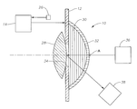
- FIG. 1 shows a cross-sectional representation of a simulator in use in an ophthalmological measurement
- FIGS. 2 a and b show two front views of the simulator according to FIG. 1 .
- a simulator denoted generally by 10 in the Figures that, as represented in FIG. 1 , is suitable for use in ophthalmological measurements includes a display apparatus 12 which is designed in the form of a self-luminous, programmable OLED display.
- the display apparatus 12 is controlled by means of an electronic control devoice 14 illustrated schematically in the Figures.
- the control device 14 controls the display apparatus 12 in such a manner that the display apparatus 12 displays an image that includes the representation of an iris 16 as well as representations of iris structures 18 and also blood-vessel structures 20 .
- An inner margin 22 of the iris 16 represented on the display apparatus 12 defines an outer margin of a representation of a pupil 24 .
- the display apparatus 12 accordingly displays an image that is suitable to simulate the arrangement of a pupillary midpoint P relative to a reference structure, in which connection an apex of a cornea and/or other eye structures—such as, for example, an outer iris margin 23 and/or the iris structures 18 and/or blood-vessel structures 20 shown in FIGS. 2 a and 2 b —may be drawn upon by way of reference structure. What is essential is merely that the reference structure remains static in the event of a variation in the pupillary diameter and in relation to, where appropriate, an associated variation in the position of the pupillary midpoint P.
- control device 14 controls the display apparatus 12 in such a manner that the display apparatus 12 , as illustrated in FIGS. 2 a and b , displays in succession various images that are suitable to simulate a variation of the pupillary diameter and an associated variation in the arrangement of the pupillary midpoint P, i.e. a pupil-centre shift relative to the chosen reference structure.
- This is brought about by the shape of the iris 16 represented on the display apparatus 12 , and hence the shape of the pupillary representation 24 bounded by the iris representation 16 relative to the chosen reference structure, being varied.
- the simulator 10 includes a brightness sensor 26 .
- the brightness centre 26 has been set up to register the intensity of ambient light and to communicate a signal that is characteristic of the intensity of ambient light to the electronic control device 14 .
- the control device 14 is programmed in such a way that it is capable of controlling the display apparatus 12 in such a manner that the display apparatus 12 displays an image that is suitable to simulate the shape of a pupil 24 , in particular the pupillary diameter and the position, dependent thereon, of the pupillary midpoint P relative to the chosen reference structure as a function of the intensity of ambient light ascertained by the brightness sensor 26 .
- the simulator 10 further includes a lens simulation 28 , an anterior-eye-chamber simulation 30 and also a cornea simulation 32 .
- the lens simulation 28 , the anterior-eye-chamber simulation 30 and the cornea simulation 32 each consist of a synthetic material, into which diffusers have been introduced in order to simulate the scattering behaviour of a natural lens, of a natural anterior eye chamber and of a natural cornea.
- the lens simulation 28 , on the one hand, and the anterior-eye-chamber simulation 30 and also the cornea simulation 32 are arranged on opposite sides of the display apparatus 12 .
- the structural design of the simulator 10 consequently corresponds to the structural design of a natural eye.
- anterior-eye-chamber simulation 30 and the cornea simulation 32 consist of materials that have been chosen in such a way that, for example, differences in refractive index do not result in perturbations of the ophthalmological measurements.
- the surfaces of these optical elements have been made antireflective and, where appropriate, correspondingly coated.
- the display apparatus 12 exhibits an aperture 34 .
- the aperture 34 at least one portion of the pupil 24 is simulated (see FIG. 2 a ), in which connection, as represented in FIG. 2 b , the pupil 24 can also be simulated completely by the aperture 34 formed in the display apparatus 12 .
- Such a configuration of the simulator 10 has the advantage that in the course of the implementation of an ophthalmological measurement electromagnetic radiation radiated onto the simulator 10 from a source 36 of electromagnetic radiation can be guided onto the lens simulation 28 which is arranged downstream of the display apparatus 12 relative to the direction of propagation of the electromagnetic radiation.
- the influence exerted on the ray guided from the radiation-source 36 onto the simulator 10 upon passing through the cornea simulation 32 , the anterior-eye-chamber simulation 30 and upon impinging on the lens simulation 28 is registered by means of a camera 38 .
- the camera 38 may likewise be used for the purpose of measuring the pupil-centre shift simulated by the simulator 10 . Alternatively, however, use may also be made of a separate camera for this purpose.
Landscapes
- Life Sciences & Earth Sciences (AREA)
- Health & Medical Sciences (AREA)
- Medical Informatics (AREA)
- Biophysics (AREA)
- Ophthalmology & Optometry (AREA)
- Engineering & Computer Science (AREA)
- Biomedical Technology (AREA)
- Heart & Thoracic Surgery (AREA)
- Physics & Mathematics (AREA)
- Molecular Biology (AREA)
- Surgery (AREA)
- Animal Behavior & Ethology (AREA)
- General Health & Medical Sciences (AREA)
- Public Health (AREA)
- Veterinary Medicine (AREA)
- Eye Examination Apparatus (AREA)
Abstract
Description
- In ophthalmological research and practice an extremely wide range of measuring devices are employed in order to measure properties of eyes. With many of these measuring instruments, electromagnetic radiation—in particular, light—is beamed onto and/or into an eye to be examined, and the influence exerted on the electromagnetic radiation by the elements of the eye and/or the influence exerted on the eye by the electromagnetic radiation is/are ascertained, in order to be able to draw inferences as to properties of the eye and, in particular, pathological changes. For example, for the purpose of preparing a refractive surgical treatment of an eye it is necessary to examine the reaction to light stimuli of the eye to be treated. In particular, a displacement of the pupillary centre as a function of the pupillary diameter, the so-called pupil-centre shift, has to be ascertained, since the pupillary midpoint customarily serves in refractive surgery as reference point for eye-tracker systems and for the positioning of an ablation profile. For such measurements of pupil-centre shift, a pupillometer described in US 2008/0309870 A1, for example, may come into operation.
- Measurement data generated by ophthalmological measuring instruments must in many cases be checked and verified by appropriate reference measurements.
- Furthermore, reference measurements are required for calibrating the measuring instruments or in connection with the development of new instruments and measuring techniques. For measuring instruments, the functional principle of which is based on the examination of the influence exerted on electromagnetic radiation beamed onto and/or into an eye to be examined by means of substantially static elements of the eye such as, for example, the cornea or the lens, for this purpose models of the eye that are described, for example, in
DE 10 2006 030 574 A1 or in WO 2009/129829 A1 may be employed, which, inter alia, include simulations of the cornea and of the lens of a human eye. The simulations consist of a synthetic material that has been doped with scattering substances in order to imitate the scattering properties of the real prototypes. However, by reason of their static structure these known eye models are not suitable to be used for reference measurements with a pupillometer that serves to examine the reaction of an eye to light stimuli, i.e. the influence exerted by light stimuli on the pupillary diameter and on the position of the pupillary centre. - An object underlying the invention is to make available a simulator that is suitable for use in reference measurements with a pupillometer.
- This object is achieved by a simulator for use in ophthalmological measurements, the simulator including a display apparatus and a control device. The control device, which, for example, may be designed in the form of an electronic control device, is adapted to control the display apparatus in such a manner that the display apparatus displays an image that is suitable to simulate the arrangement of a pupillary midpoint relative to a reference structure. In particular, the electronic control device is adapted to control the display apparatus of the simulator according to the invention in such a manner that the display apparatus displays in succession various images that are suitable to simulate various arrangements of a pupillary midpoint relative to a reference structure. In other words, the simulator according to the invention does not have a static structure but enables, through the use of a display apparatus for representing on the display apparatus various images simulating the arrangement of a pupillary midpoint relative to a reference structure, a simple and convenient simulation of a pupil-centre shift.
- The images displayed by the display apparatus of the simulator can be gauged by a pupillometer. Subsequently the measured values registered by the pupillometer can be compared with the position of the pupillary midpoint, known from the structural design of the simulator and also from the programming of the control device, in the image represented by the display apparatus of the simulator, and the findings obtained in the course of this comparison can, for example, be utilised for verifying the measured values ascertained by the pupillometer and/or for calibrating the pupillometer. The simulator according to the invention can consequently be drawn upon for reference measurements with a pupillometer or with a higher-order diagnostic or therapeutic instrument having a pupillometric function. In particular, the simulator according to the invention can be used for testing the reaction of an eye-tracking system to a moving pupil and hence for testing the functionality of the eye-tracking system.
- The control device is preferentially adapted to control the display apparatus in such a manner that the display apparatus displays in succession a plurality of images that are adapted to simulate a variation of the arrangement of a pupillary midpoint relative to a reference structure that has been adapted to the physiological response of a natural eye. In other words, the control device is preferentially programmed in such a way that it is adapted to control the display apparatus in such a manner that the images displayed on the display apparatus simulate the pupil-centre shift of a natural eye reproducibly. A simulator that enables a simulation, as realistic as possible, of the pupil-centre shift of a natural eye permits the implementation of realistic reference measurements. The results of reference measurements carried out under realistic conditions can be transferred particularly well to the real use of the ophthalmological diagnostic or therapeutic instrument.
- The control device is preferentially adapted to control the display apparatus in such a manner that the display apparatus displays an image that includes a representation of an iris. An iris is comparatively easy to represent on the display apparatus, in which connection an inner margin of the iris may be regarded as a boundary margin of a pupil. By variation of the shape of the iris in the image represented by the display apparatus, a variation of the pupillary diameter and/or a variation of the arrangement of a pupillary midpoint relative to a reference structure can consequently be simulated in straightforward manner.
- Under the control of the control device of the simulator according to the invention, various reference structures may be utilised for the variable relative positioning of the pupillary midpoint. For example, the control device of the simulator according to the invention may be adapted to control the display apparatus in such a manner that the display apparatus displays an image that is adapted to simulate the arrangement of a pupillary midpoint relative to an apex of a cornea. Such a configuration of the simulator is particularly advantageous when the ophthalmological diagnostic or therapeutic instrument with which reference measurements in respect of the simulator are to be performed customarily draws upon the apex of the cornea by way of reference point in the course of a measurement of the pupil-centre shift.
- Additionally or alternatively, however, the control device may also be adapted to control the display apparatus in such a manner that the display apparatus displays an image that is adapted to simulate the arrangement of a pupillary midpoint relative to an eye structure differing from an apex of a cornea. For example, at least one of an outer iris margin, iris structures and blood-vessel structures may be drawn upon, in addition to or as an alternative to an apex of a cornea, by way of reference structures for the positioning of the pupillary midpoint. For this purpose the control device may have been programmed in such a way that it is adapted to control the display apparatus in such a manner that the display apparatus displays an image that includes eye structures such as, for example, at least one of an iris with an outer iris margin, iris structures and blood-vessel structures. From the structural design of the simulator and also from the programming of the control device, the variable position of the pupillary midpoint in the image represented by the display apparatus of the simulator relative to the chosen reference structure(s) is then known and may be compared with the measured values that are obtained by a diagnostic or therapeutic instrument gauging the images displayed by the display apparatus of the simulator.
- By virtue of the possibility of selecting various and/or several reference structures, the simulator may be adapted particularly flexibly to variously configured diagnostic or therapeutic instruments. This means that diagnostic or therapeutic instruments that in real operation utilise at least one of an outer iris margin, iris structures and blood-vessel structures by way of reference structure may also gauge the simulator by utilising at least one of an outer iris margin, iris structures and blood-vessel structures by way of reference structure(s).
- In a preferred embodiment of the simulator according to the invention, the display apparatus includes a self-luminous display. For example, an OLED (organic light-emitting diode) display may come into operation by way of self-luminous display. In the case where a self-luminous display is employed in the display apparatus of the simulator according to the invention, an influence exerted on the image represented on the display apparatus by external illumination or by electromagnetic radiation directed onto the simulator by an ophthalmological diagnostic or therapeutic instrument is minimised. This enables an increase in the accuracy of measurement.
- Furthermore, the display apparatus of the simulator according to the invention may include a foil display. By means of a foil display, the real shape of an eye can be simulated, as a result of which the design of the simulator becomes still more realistic.
- The simulator according to the invention may further include at least one of a lens simulation, an eye-chamber simulation and a cornea simulation. These simulations may consist of a synthetic material and, if desired, may contain diffusers, by means of which the scattering properties of the simulations may be adapted to the scattering properties of their natural prototypes. Furthermore, the simulations may exhibit fluorescent properties. The positions of the simulations in the simulator are preferentially adapted to the positions of their natural prototypes in a natural eye. The display apparatus is therefore positioned in a simulator including a lens simulation, an anterior-eye-chamber simulation and a cornea simulation, preferentially between the anterior-eye-chamber simulation and the lens simulation. The cornea simulation, on the other hand, is arranged on a side of the anterior-eye-chamber simulation facing away from the display apparatus.
- Optical elements serving, in particular, for simulating an anterior portion of an eye, i.e. an anterior eye chamber and a cornea for example, are preferentially designed in such a way that the implementation of at least one of topographical measurements with a Placido system and Scheimpflug measurements in respect of the simulator is/are possible. For this purpose these optical elements preferentially consist of materials that have been chosen in such a way that mirror effects and/or differences in refractive index at the relevant illumination wavelengths and measurement wavelengths do not result in perturbations of the measurements. Furthermore, the surfaces of these optical elements may be provided with appropriate surface coatings and/or may be made antireflective, in order to avoid perturbations of the measurements. It will be understood that the configuration of the simulations, just like the programming of the control device and the image representation on the display apparatus, may be adapted to the specific configuration of an ophthalmological diagnostic or therapeutic instrument with which the simulator is to be gauged.
- In a preferred embodiment of the simulator according to the invention, the display apparatus exhibits an aperture by which, in operation of the simulator, at least a portion of a pupil is simulated. In the region of the aperture formed in the display apparatus a lens simulation may be arranged. A simulator configured in such a manner is distinguished by particular closeness to reality.
- Finally, the simulator according to the invention may include a brightness sensor which is adapted to measure the intensity of ambient light and to communicate signals that are characteristic of the intensity of ambient light to the control device. The control device may then be adapted to control the display apparatus in such a manner that the display apparatus displays an image that is suitable to simulate the arrangement of a pupillary midpoint relative to a reference structure as a function of a signal that is registered by the brightness sensor and that is characteristic of the intensity of ambient light. In other words, the control device may be adapted to control the display apparatus in such a manner that the display apparatus displays an image that is suitable to simulate an arrangement of a pupillary midpoint relative to a reference structure in a manner adapted to the physiological response of a natural eye, as a function of the intensity of ambient light. A simulator equipped with a brightness sensor and with an appropriately programmed control device is adapted to simulate particularly realistically the variation in pupillary diameter and the pupil-centre shift of a natural eye as a function of the intensity of ambient light.
- A preferred embodiment of the invention will now be elucidated in more detail on the basis of the appended schematic drawings, in which
-
FIG. 1 shows a cross-sectional representation of a simulator in use in an ophthalmological measurement and -
FIGS. 2 a and b show two front views of the simulator according toFIG. 1 . - A simulator denoted generally by 10 in the Figures that, as represented in
FIG. 1 , is suitable for use in ophthalmological measurements includes adisplay apparatus 12 which is designed in the form of a self-luminous, programmable OLED display. Thedisplay apparatus 12 is controlled by means of anelectronic control devoice 14 illustrated schematically in the Figures. As can best be discerned inFIGS. 2 a and b, thecontrol device 14 controls thedisplay apparatus 12 in such a manner that thedisplay apparatus 12 displays an image that includes the representation of aniris 16 as well as representations ofiris structures 18 and also blood-vessel structures 20. - An
inner margin 22 of theiris 16 represented on thedisplay apparatus 12 defines an outer margin of a representation of apupil 24. Thedisplay apparatus 12 accordingly displays an image that is suitable to simulate the arrangement of a pupillary midpoint P relative to a reference structure, in which connection an apex of a cornea and/or other eye structures—such as, for example, anouter iris margin 23 and/or theiris structures 18 and/or blood-vessel structures 20 shown inFIGS. 2 a and 2 b—may be drawn upon by way of reference structure. What is essential is merely that the reference structure remains static in the event of a variation in the pupillary diameter and in relation to, where appropriate, an associated variation in the position of the pupillary midpoint P. - In particular, the
control device 14 controls thedisplay apparatus 12 in such a manner that thedisplay apparatus 12, as illustrated inFIGS. 2 a and b, displays in succession various images that are suitable to simulate a variation of the pupillary diameter and an associated variation in the arrangement of the pupillary midpoint P, i.e. a pupil-centre shift relative to the chosen reference structure. This is brought about by the shape of theiris 16 represented on thedisplay apparatus 12, and hence the shape of thepupillary representation 24 bounded by theiris representation 16 relative to the chosen reference structure, being varied. - In order to enable a simulation of a pupil-centre shift adapted to the physiological response of a natural eye, the
simulator 10 includes abrightness sensor 26. Thebrightness centre 26 has been set up to register the intensity of ambient light and to communicate a signal that is characteristic of the intensity of ambient light to theelectronic control device 14. Furthermore, thecontrol device 14 is programmed in such a way that it is capable of controlling thedisplay apparatus 12 in such a manner that thedisplay apparatus 12 displays an image that is suitable to simulate the shape of apupil 24, in particular the pupillary diameter and the position, dependent thereon, of the pupillary midpoint P relative to the chosen reference structure as a function of the intensity of ambient light ascertained by thebrightness sensor 26. - As can best be discerned in
FIG. 1 , thesimulator 10 further includes alens simulation 28, an anterior-eye-chamber simulation 30 and also acornea simulation 32. Thelens simulation 28, the anterior-eye-chamber simulation 30 and thecornea simulation 32 each consist of a synthetic material, into which diffusers have been introduced in order to simulate the scattering behaviour of a natural lens, of a natural anterior eye chamber and of a natural cornea. Thelens simulation 28, on the one hand, and the anterior-eye-chamber simulation 30 and also thecornea simulation 32, on the other hand, are arranged on opposite sides of thedisplay apparatus 12. The structural design of thesimulator 10 consequently corresponds to the structural design of a natural eye. In particular, the anterior-eye-chamber simulation 30 and thecornea simulation 32 consist of materials that have been chosen in such a way that, for example, differences in refractive index do not result in perturbations of the ophthalmological measurements. Furthermore, the surfaces of these optical elements have been made antireflective and, where appropriate, correspondingly coated. - From
FIGS. 1 and 2 a it can further be gathered that thedisplay apparatus 12 exhibits anaperture 34. By virtue of theaperture 34, at least one portion of thepupil 24 is simulated (seeFIG. 2 a), in which connection, as represented inFIG. 2 b, thepupil 24 can also be simulated completely by theaperture 34 formed in thedisplay apparatus 12. Such a configuration of thesimulator 10 has the advantage that in the course of the implementation of an ophthalmological measurement electromagnetic radiation radiated onto thesimulator 10 from asource 36 of electromagnetic radiation can be guided onto thelens simulation 28 which is arranged downstream of thedisplay apparatus 12 relative to the direction of propagation of the electromagnetic radiation. - As is further evident from
FIG. 1 , in the course of the implementation of an ophthalmological measurement with the aid of thesimulator 10 the influence exerted on the ray guided from the radiation-source 36 onto thesimulator 10 upon passing through thecornea simulation 32, the anterior-eye-chamber simulation 30 and upon impinging on thelens simulation 28 is registered by means of acamera 38. Thecamera 38 may likewise be used for the purpose of measuring the pupil-centre shift simulated by thesimulator 10. Alternatively, however, use may also be made of a separate camera for this purpose.
Claims (10)
Priority Applications (1)
| Application Number | Priority Date | Filing Date | Title |
|---|---|---|---|
| US12/894,314 US8562133B2 (en) | 2010-09-30 | 2010-09-30 | Simulator for use in ophthalmological measurements |
Applications Claiming Priority (1)
| Application Number | Priority Date | Filing Date | Title |
|---|---|---|---|
| US12/894,314 US8562133B2 (en) | 2010-09-30 | 2010-09-30 | Simulator for use in ophthalmological measurements |
Publications (2)
| Publication Number | Publication Date |
|---|---|
| US20120081663A1 true US20120081663A1 (en) | 2012-04-05 |
| US8562133B2 US8562133B2 (en) | 2013-10-22 |
Family
ID=45889541
Family Applications (1)
| Application Number | Title | Priority Date | Filing Date |
|---|---|---|---|
| US12/894,314 Expired - Fee Related US8562133B2 (en) | 2010-09-30 | 2010-09-30 | Simulator for use in ophthalmological measurements |
Country Status (1)
| Country | Link |
|---|---|
| US (1) | US8562133B2 (en) |
Cited By (5)
| Publication number | Priority date | Publication date | Assignee | Title |
|---|---|---|---|---|
| WO2014059533A1 (en) * | 2012-10-19 | 2014-04-24 | The Hospital For Sick Children | System, method and computer program for training for ophthalmic examinations |
| US9478157B2 (en) * | 2014-11-17 | 2016-10-25 | Apple Inc. | Ambient light adaptive displays |
| US9530362B2 (en) | 2014-12-23 | 2016-12-27 | Apple Inc. | Ambient light adaptive displays with paper-like appearance |
| CN112914500A (en) * | 2021-03-16 | 2021-06-08 | 首都医科大学附属北京儿童医院 | Artificial eye simulation device suitable for infant eyeball motion detection |
| US20210192978A1 (en) * | 2018-09-05 | 2021-06-24 | Tellyes Scientific Inc. | Eyepiece, eye simulator device, mannequin simulator and training method |
Families Citing this family (1)
| Publication number | Priority date | Publication date | Assignee | Title |
|---|---|---|---|---|
| US11276329B2 (en) | 2017-03-31 | 2022-03-15 | Cae Healthcare Canada Inc. | Artificial eye system comprising a see-through display |
Citations (10)
| Publication number | Priority date | Publication date | Assignee | Title |
|---|---|---|---|---|
| US5661538A (en) * | 1995-11-15 | 1997-08-26 | Fairville Medical Optics, Inc. | Portable self-measurement pupillometer with active opto-electronic centering aid and method for use thereof |
| US5900923A (en) * | 1996-11-26 | 1999-05-04 | Medsim-Eagle Simulation, Inc. | Patient simulator eye dilation device |
| US6257721B1 (en) * | 1999-02-22 | 2001-07-10 | Nidek Co., Ltd. | Device for spectacles |
| US20020036749A1 (en) * | 2000-09-28 | 2002-03-28 | Nidek Co., Ltd. | Ophthalmic apparatus |
| US20050254008A1 (en) * | 2002-06-14 | 2005-11-17 | Ferguson R D | Monitoring blood flow in the retina using a line-scanning laser ophthalmoscope |
| US20060250684A1 (en) * | 2005-04-21 | 2006-11-09 | Ulrich Sander | Optical System With Display |
| US20080094689A1 (en) * | 2004-11-12 | 2008-04-24 | Koninklijke Philips Electronics, N.V. | Bright Full Color Reflective Display |
| US20080201329A1 (en) * | 2007-02-21 | 2008-08-21 | Yiling Xie | Method And The Associate Mechanism For Stored-Image Database-Driven Spectacle Frame Fitting Services Over Public Network |
| US20100220897A1 (en) * | 2009-02-27 | 2010-09-02 | Kabushiki Kaisha Toshiba | Information processing apparatus and network conference system |
| US20100231857A1 (en) * | 2005-03-22 | 2010-09-16 | Amo Manufacturing Usa, Llc | Pupilometer For Pupil Center Drift and Pupil Size Measurements at Differing Viewing Distances |
Family Cites Families (2)
| Publication number | Priority date | Publication date | Assignee | Title |
|---|---|---|---|---|
| US6576013B1 (en) | 2002-01-08 | 2003-06-10 | International Business Machines Corporation | Eye prosthesis |
| ES2439251T3 (en) | 2008-04-25 | 2014-01-22 | Wavelight Gmbh | Eye model for use in ophthalmological measurements |
-
2010
- 2010-09-30 US US12/894,314 patent/US8562133B2/en not_active Expired - Fee Related
Patent Citations (10)
| Publication number | Priority date | Publication date | Assignee | Title |
|---|---|---|---|---|
| US5661538A (en) * | 1995-11-15 | 1997-08-26 | Fairville Medical Optics, Inc. | Portable self-measurement pupillometer with active opto-electronic centering aid and method for use thereof |
| US5900923A (en) * | 1996-11-26 | 1999-05-04 | Medsim-Eagle Simulation, Inc. | Patient simulator eye dilation device |
| US6257721B1 (en) * | 1999-02-22 | 2001-07-10 | Nidek Co., Ltd. | Device for spectacles |
| US20020036749A1 (en) * | 2000-09-28 | 2002-03-28 | Nidek Co., Ltd. | Ophthalmic apparatus |
| US20050254008A1 (en) * | 2002-06-14 | 2005-11-17 | Ferguson R D | Monitoring blood flow in the retina using a line-scanning laser ophthalmoscope |
| US20080094689A1 (en) * | 2004-11-12 | 2008-04-24 | Koninklijke Philips Electronics, N.V. | Bright Full Color Reflective Display |
| US20100231857A1 (en) * | 2005-03-22 | 2010-09-16 | Amo Manufacturing Usa, Llc | Pupilometer For Pupil Center Drift and Pupil Size Measurements at Differing Viewing Distances |
| US20060250684A1 (en) * | 2005-04-21 | 2006-11-09 | Ulrich Sander | Optical System With Display |
| US20080201329A1 (en) * | 2007-02-21 | 2008-08-21 | Yiling Xie | Method And The Associate Mechanism For Stored-Image Database-Driven Spectacle Frame Fitting Services Over Public Network |
| US20100220897A1 (en) * | 2009-02-27 | 2010-09-02 | Kabushiki Kaisha Toshiba | Information processing apparatus and network conference system |
Cited By (12)
| Publication number | Priority date | Publication date | Assignee | Title |
|---|---|---|---|---|
| WO2014059533A1 (en) * | 2012-10-19 | 2014-04-24 | The Hospital For Sick Children | System, method and computer program for training for ophthalmic examinations |
| CN103959357A (en) * | 2012-10-19 | 2014-07-30 | 儿童医院 | System, method and computer program for training for ophthalmic examinations |
| US20150279238A1 (en) * | 2012-10-19 | 2015-10-01 | The Hospital For Sick Children | System, method and computer program for training for ophthalmic examinations |
| US10083631B2 (en) * | 2012-10-19 | 2018-09-25 | The Hospital For Sick Children | System, method and computer program for training for ophthalmic examinations |
| US9478157B2 (en) * | 2014-11-17 | 2016-10-25 | Apple Inc. | Ambient light adaptive displays |
| US9947259B2 (en) | 2014-11-17 | 2018-04-17 | Apple Inc. | Ambient light adaptive displays |
| US9530362B2 (en) | 2014-12-23 | 2016-12-27 | Apple Inc. | Ambient light adaptive displays with paper-like appearance |
| US10192519B2 (en) | 2014-12-23 | 2019-01-29 | Apple Inc. | Ambient light adaptive displays with paper-like appearance |
| US10867578B2 (en) | 2014-12-23 | 2020-12-15 | Apple Inc. | Ambient light adaptive displays with paper-like appearance |
| US20210192978A1 (en) * | 2018-09-05 | 2021-06-24 | Tellyes Scientific Inc. | Eyepiece, eye simulator device, mannequin simulator and training method |
| US11967250B2 (en) * | 2018-09-05 | 2024-04-23 | Tellyes Scientific Inc. | Eyepiece, eye simulator device, mannequin simulator and training method |
| CN112914500A (en) * | 2021-03-16 | 2021-06-08 | 首都医科大学附属北京儿童医院 | Artificial eye simulation device suitable for infant eyeball motion detection |
Also Published As
| Publication number | Publication date |
|---|---|
| US8562133B2 (en) | 2013-10-22 |
Similar Documents
| Publication | Publication Date | Title |
|---|---|---|
| US8562133B2 (en) | Simulator for use in ophthalmological measurements | |
| JP6731850B2 (en) | Threshold inspection and determination | |
| ES2616462T3 (en) | Process and apparatus to determine the optical aberrations of an eye | |
| CA2710160C (en) | Dual scheimpflug system for three-dimensional analysis of an eye | |
| EP3223679B1 (en) | Photobleaching device and method and dark adapted perimetry device and dark adapted perimetry method | |
| US11288981B2 (en) | System and method for training use of pressure equalization tube delivery instrument | |
| US9519830B2 (en) | Ophthalmologic image processing method and storage medium storing program for executing the method | |
| KR20140111298A (en) | Video game to monitor visual field loss in glaucoma | |
| US11311187B2 (en) | Methods and systems for corneal topography with in-focus scleral imaging | |
| CN109303544B (en) | A multi-scale mixed vision impairment analyzer and its analysis method | |
| JP3129404B2 (en) | Glare contrast tester | |
| JP2015524302A (en) | Apparatus for measuring shape and thickness of cornea and measuring method used | |
| Gobbi et al. | Optomechanical eye model with imaging capabilities for objective evaluation of intraocular lenses | |
| US8511821B2 (en) | Eye model for use in ophthalmological measurements | |
| JP2009136424A (en) | Ophthalmic equipment | |
| CN106725280B (en) | A kind of slant visibility measuring device | |
| Vohnsen | The retina and the Stiles–Crawford effects | |
| AU2014412856A1 (en) | Model eye producing a speckle pattern having a reduced bright-to-dark ratio for use with optical measurement system for cataract diagnostics | |
| Redaelli et al. | Non-contact tonometry: predicting intraocular pressure using a material—corneal thickness—independent methodology | |
| DE102010047135B4 (en) | Simulation device for use in ophthalmic measurements | |
| JP2020505091A (en) | Calibration method for camera-type measuring device for human eye diagnosis | |
| CN214965416U (en) | Artificial artificial eye for replacing human eye for ophthalmologic equipment examination | |
| RU2420223C2 (en) | Device for visual field examination | |
| CN204683560U (en) | A kind of monotubular eyeshield for visual performance and special visual performance tester | |
| CN118284357B (en) | Determining visual performance of a person's eyes |
Legal Events
| Date | Code | Title | Description |
|---|---|---|---|
| AS | Assignment |
Owner name: WAVELIGHT GMBH, GERMANY Free format text: ASSIGNMENT OF ASSIGNORS INTEREST;ASSIGNORS:SCHMID, STEFAN;WARM, BERNDT, DR.;SIGNING DATES FROM 20110909 TO 20110912;REEL/FRAME:026987/0510 |
|
| STCF | Information on status: patent grant |
Free format text: PATENTED CASE |
|
| FPAY | Fee payment |
Year of fee payment: 4 |
|
| AS | Assignment |
Owner name: ALCON INC., SWITZERLAND Free format text: CONFIRMATORY DEED OF ASSIGNMENT EFFECTIVE APRIL 8, 2019;ASSIGNOR:WAVELIGHT GMBH;REEL/FRAME:051257/0835 Effective date: 20191111 |
|
| MAFP | Maintenance fee payment |
Free format text: PAYMENT OF MAINTENANCE FEE, 8TH YEAR, LARGE ENTITY (ORIGINAL EVENT CODE: M1552); ENTITY STATUS OF PATENT OWNER: LARGE ENTITY Year of fee payment: 8 |
|
| FEPP | Fee payment procedure |
Free format text: MAINTENANCE FEE REMINDER MAILED (ORIGINAL EVENT CODE: REM.); ENTITY STATUS OF PATENT OWNER: LARGE ENTITY |
|
| LAPS | Lapse for failure to pay maintenance fees |
Free format text: PATENT EXPIRED FOR FAILURE TO PAY MAINTENANCE FEES (ORIGINAL EVENT CODE: EXP.); ENTITY STATUS OF PATENT OWNER: LARGE ENTITY |
|
| STCH | Information on status: patent discontinuation |
Free format text: PATENT EXPIRED DUE TO NONPAYMENT OF MAINTENANCE FEES UNDER 37 CFR 1.362 |
|
| FP | Lapsed due to failure to pay maintenance fee |
Effective date: 20251022 |