US20110299814A1 - Duplex optical connector unit - Google Patents
Duplex optical connector unit Download PDFInfo
- Publication number
- US20110299814A1 US20110299814A1 US13/116,287 US201113116287A US2011299814A1 US 20110299814 A1 US20110299814 A1 US 20110299814A1 US 201113116287 A US201113116287 A US 201113116287A US 2011299814 A1 US2011299814 A1 US 2011299814A1
- Authority
- US
- United States
- Prior art keywords
- optical
- holder
- pair
- connector unit
- optical connector
- Prior art date
- Legal status (The legal status is an assumption and is not a legal conclusion. Google has not performed a legal analysis and makes no representation as to the accuracy of the status listed.)
- Abandoned
Links
- 230000003287 optical effect Effects 0.000 title claims abstract description 200
- 239000013307 optical fiber Substances 0.000 claims description 30
- 239000000835 fiber Substances 0.000 description 24
- 230000002787 reinforcement Effects 0.000 description 7
- 230000007175 bidirectional communication Effects 0.000 description 3
- 230000006854 communication Effects 0.000 description 1
- 230000002950 deficient Effects 0.000 description 1
- 230000009977 dual effect Effects 0.000 description 1
- 230000000694 effects Effects 0.000 description 1
- 229920001971 elastomer Polymers 0.000 description 1
- 239000000806 elastomer Substances 0.000 description 1
- 238000003780 insertion Methods 0.000 description 1
- 230000037431 insertion Effects 0.000 description 1
- 239000000463 material Substances 0.000 description 1
- 230000002093 peripheral effect Effects 0.000 description 1
- 239000002699 waste material Substances 0.000 description 1
Images




Classifications
-
- G—PHYSICS
- G02—OPTICS
- G02B—OPTICAL ELEMENTS, SYSTEMS OR APPARATUS
- G02B6/00—Light guides; Structural details of arrangements comprising light guides and other optical elements, e.g. couplings
- G02B6/24—Coupling light guides
- G02B6/36—Mechanical coupling means
- G02B6/38—Mechanical coupling means having fibre to fibre mating means
- G02B6/3807—Dismountable connectors, i.e. comprising plugs
- G02B6/3873—Connectors using guide surfaces for aligning ferrule ends, e.g. tubes, sleeves, V-grooves, rods, pins, balls
- G02B6/3874—Connectors using guide surfaces for aligning ferrule ends, e.g. tubes, sleeves, V-grooves, rods, pins, balls using tubes, sleeves to align ferrules
- G02B6/3878—Connectors using guide surfaces for aligning ferrule ends, e.g. tubes, sleeves, V-grooves, rods, pins, balls using tubes, sleeves to align ferrules comprising a plurality of ferrules, branching and break-out means
- G02B6/3879—Linking of individual connector plugs to an overconnector, e.g. using clamps, clips, common housings comprising several individual connector plugs
-
- G—PHYSICS
- G02—OPTICS
- G02B—OPTICAL ELEMENTS, SYSTEMS OR APPARATUS
- G02B6/00—Light guides; Structural details of arrangements comprising light guides and other optical elements, e.g. couplings
- G02B6/24—Coupling light guides
- G02B6/36—Mechanical coupling means
- G02B6/38—Mechanical coupling means having fibre to fibre mating means
- G02B6/3807—Dismountable connectors, i.e. comprising plugs
- G02B6/3887—Anchoring optical cables to connector housings, e.g. strain relief features
- G02B6/38875—Protection from bending or twisting
-
- G—PHYSICS
- G02—OPTICS
- G02B—OPTICAL ELEMENTS, SYSTEMS OR APPARATUS
- G02B6/00—Light guides; Structural details of arrangements comprising light guides and other optical elements, e.g. couplings
- G02B6/24—Coupling light guides
- G02B6/36—Mechanical coupling means
- G02B6/38—Mechanical coupling means having fibre to fibre mating means
- G02B6/3807—Dismountable connectors, i.e. comprising plugs
- G02B6/381—Dismountable connectors, i.e. comprising plugs of the ferrule type, e.g. fibre ends embedded in ferrules, connecting a pair of fibres
- G02B6/3825—Dismountable connectors, i.e. comprising plugs of the ferrule type, e.g. fibre ends embedded in ferrules, connecting a pair of fibres with an intermediate part, e.g. adapter, receptacle, linking two plugs
-
- G—PHYSICS
- G02—OPTICS
- G02B—OPTICAL ELEMENTS, SYSTEMS OR APPARATUS
- G02B6/00—Light guides; Structural details of arrangements comprising light guides and other optical elements, e.g. couplings
- G02B6/24—Coupling light guides
- G02B6/36—Mechanical coupling means
- G02B6/38—Mechanical coupling means having fibre to fibre mating means
- G02B6/3807—Dismountable connectors, i.e. comprising plugs
- G02B6/3887—Anchoring optical cables to connector housings, e.g. strain relief features
- G02B6/3888—Protection from over-extension or over-compression
-
- G—PHYSICS
- G02—OPTICS
- G02B—OPTICAL ELEMENTS, SYSTEMS OR APPARATUS
- G02B6/00—Light guides; Structural details of arrangements comprising light guides and other optical elements, e.g. couplings
- G02B6/24—Coupling light guides
- G02B6/36—Mechanical coupling means
- G02B6/38—Mechanical coupling means having fibre to fibre mating means
- G02B6/3807—Dismountable connectors, i.e. comprising plugs
- G02B6/389—Dismountable connectors, i.e. comprising plugs characterised by the method of fastening connecting plugs and sockets, e.g. screw- or nut-lock, snap-in, bayonet type
- G02B6/3893—Push-pull type, e.g. snap-in, push-on
Definitions
- a pair of optical connectors 102 a , 102 b fixed to leading ends of the pair of optical fiber cables 101 a , 101 b , a holder 103 for holding the pair of optical connectors 102 a , 102 b , and boots 104 a , 104 b for protecting the pair of optical fiber cables 101 a , 101 b extending from the holder 103 .
- the above-mentioned trouble can be eliminated by exchanging the positions of a pair of optical connectors.
- the entire optical connector unit is reversed upside down, that is, when the optical connector unit is rotated 180 degrees about an optical axis direction (direction in which the optical fiber extends)
- the positions of the input optical connector and the output optical connector can be exchanged.
- the optical connectors 202 a , 202 b which are provided with locking levers 207 a , 207 b
- the locking levers 207 a , 207 b face downward, with the result that the optical connectors cannot be mounted to the optical adapter.
- FIG. 5 A perspective view illustrating a step of exchanging a pair of optical connectors of the optical connector unit (a state in which the boot is detached).
- FIG. 10 A perspective view illustrating a conventional optical connector unit.
Landscapes
- Physics & Mathematics (AREA)
- General Physics & Mathematics (AREA)
- Optics & Photonics (AREA)
- Mechanical Coupling Of Light Guides (AREA)
Abstract
Provided is a duplex optical connector unit, in which locking levers extending obliquely upward toward a proximal end side and including interlocking portions engaging with an optical adapter are provided on top surfaces of housings of optical connectors, and an operation lever extending obliquely upward toward a leading end side and including a pressing part located above the locking levers is provided in a top surface of a main body portion of a boot.
Description
- The present invention relates to an optical connector, and more particularly, to a duplex optical connector unit for bidirectional communication including a pair of optical connectors.
- An optical connector is fixed to a leading end of an optical fiber, and is used for connecting the optical fiber to another optical fiber or an optical communication module via an optical adapter or an optical receptacle. A duplex optical connector unit for bidirectional communication including an input optical connector and an output optical connector (hereinafter, also simply referred to as “optical connector unit”) is known as a kind of optical connector (for example, see Patent Literature 1).
- As a cable for bidirectional communication, for example, as illustrated in
FIG. 8 , there is known aduplex cable 101 having a spectacles-like cross-sectional shape, which is formed by integrally joining twooptical fiber cables optical fiber cables bare fiber 112 incorporating anoptical fiber 111, and areinforcement fiber 113 and acovering tube 114 covering an outer periphery of thebare fiber 112. Anoptical connector unit 100 to be connected to theduplex cable 101 having a spectacles-like cross-sectional shape includes, for example, as illustrated inFIG. 9 , a pair ofoptical connectors optical fiber cables holder 103 for holding the pair ofoptical connectors boots 104 a, 104 b for protecting the pair ofoptical fiber cables holder 103. - Such an
optical connector unit 100 has a problem in that theduplex cable 101 bifurcates to the twooptical fiber cables optical connector unit 100 takes a large mounting space. Further, the twoboots 104 a, 104 b need to be provided for protecting the two bifurcatedoptical fiber cables - Further, when the
optical connector unit 100 is mounted to the optical adapter, theoptical connector unit 100 needs to be rotated so as to fit to a mounting portion of the optical adapter. At this time, a twist occurs in theduplex cable 101. However, theduplex cable 101 has a flat spectacles-like cross-sectional shape as illustrated inFIG. 8 , and hence it is difficult to smoothly twist theduplex cable 101 particularly when theduplex cable 101 is curved. As a result, theoptical connector unit 100 resists rotation, which leads to poor mounting workability. Further, when the optical connector unit is connected to each of a plurality of connection terminals provided in an appliance, a plurality of cables extending from the optical connector unit are arranged by tying the plurality of cables together. However, it is difficult to tie theduplex cables 101 together due to its spectacles-like cross-sectional shape, and thus the arrangement of the wiring is difficult. Moreover, not only is it difficult to rotate oneduplex cable 101 having a spectacles-like cross-sectional shape, but also it becomes more difficult to rotate the plurality ofduplex cables 101 tied together because the cables interfere with each other, which leads to poor wiring workability. - Then, in
Patent Literature 2, the inventor of the present invention proposed anoptical connector unit 200 as illustrated inFIG. 10 . Theoptical connector unit 200 has a structure to which aduplex cable 201 having a substantially circular cross-sectional shape can be fixed, theduplex cable 201 being formed by providing a pair of optical fibers inside one covering tube. As illustrated inFIG. 11 , theduplex cable 201 includes twobare fibers 212 incorporatingoptical fibers 211, acovering tube 214 covering outer peripheries of thebare fibers 212, and areinforcement fiber 213 filled between thecovering tube 214 and thebare fibers 212. As illustrated inFIG. 10 , theoptical connector unit 200 includes a pair ofoptical connectors holder 203 for holding the pair ofoptical connector boot 204 fitted to theholder 103. Thedual cable 201 is fixed to theholder 203, and the pair of optical fibers bifurcate inside theholder 203 so as to be connected to theoptical connectors - According to the
optical connector unit 200, the two bifurcated optical fiber cables are not exposed to the outside, and hence space saving is achieved. Further, oneboot 204 is enough, and hence the unit can be downsized compared to theoptical connector unit 100 as illustrated inFIG. 9 and the number of components can be reduced. Moreover, it is easy to tie theduplex cable 201 due to its substantially circular cross-sectional shape, and thus the arrangement of the wiring is easy. Further, even a curved cable or a plurality of cables tied together can be smoothly twisted. Thus, theoptical connector unit 200 is rotated more easily, which facilitates wiring work. -
- Patent Literature 1: JP 2000-315821 A
- Patent Literature 2: JP 2005-189288 A
- In the optical connector unit as described above, an input optical connector and an output optical connector are mounted to an input mounting portion and an output mounting portion of an optical adapter (or optical receptacle, the same shall apply hereinafter), respectively. Therefore, in assembling the optical connector unit, when the input optical connector and the output optical connector are reversely assembled by mistake, both the optical connectors are not adapted to the mounting portions of the optical adapter. The optical connector unit thus assembled is not usable, and hence the optical connector unit together with a duplex cable fixed thereto becomes useless.
- Further, for example, in the case of the optical connector unit to be mounted to the optical adapter provided as an optical connection terminal of an electronic device, even if the optical connector unit to be connected from outside of the electronic device is correctly assembled, when the input optical connector and the output optical connector are reversely mounted to the mounting portions inside the optical adapter, it is impossible to correctly connect an optical fiber. In this case, it is possible to deal with this situation by opening a casing of the electronic device and exchanging the positions of the optical connectors inside the casing. However, work of opening the casing of the electronic device is troublesome, and hence it is desired to complete the exchange of the positions of the optical connectors on the optical connector unit side to be connected from outside of the electronic device if circumstances allow.
- The above-mentioned trouble can be eliminated by exchanging the positions of a pair of optical connectors. For example, when the entire optical connector unit is reversed upside down, that is, when the optical connector unit is rotated 180 degrees about an optical axis direction (direction in which the optical fiber extends), the positions of the input optical connector and the output optical connector can be exchanged. However, for example, as illustrated in
FIG. 10 , in the case of theoptical connectors locking levers locking levers - Alternatively, it is conceivable that the positions of the
optical connectors FIGS. 12A to 12C . More specifically, the pair ofoptical connectors locking levers FIG. 12A ) are each reversed upside down relative to a holder 203 (seeFIG. 12B ), and then the entireoptical connector unit 200 is reversed upside down (seeFIG. 12C ). However, theholder 203 of theoptical connector unit 200 is provided with anoperation lever 208 for pressing thelocking levers FIG. 10 ). Therefore, when theoptical connectors holder 203 as illustrated inFIG. 12B , the locking levers 207 a, 207 b and theoperation lever 208 are disposed vertically on opposite sides, resulting in a defective assembly. - An object to be achieved by the present invention is to provide an optical connector unit which includes the locking levers and the operation lever and enables the pair of optical connectors to be easily exchanged in position.
- In order to achieve the above-mentioned object, the present invention provides a duplex optical connector unit, which is fixed to a leading end of a duplex cable including a pair of optical fibers therein, including: a pair of optical connectors, each of which includes a ferrule provided to a leading end of each of the pair of optical fibers, a housing for holding the ferrule, and a locking lever extending obliquely upward from a top surface of the housing toward a proximal end side, the pair of optical connectors each being provided at the leading end of each of the pair of optical fibers; a holder, which includes connector fixing portions for fixing the pair of optical connectors, and a cable fixing portion for fixing the duplex cable; and a boot, which includes a main body portion fitted to the holder and covering an outer periphery of the duplex cable, an operation lever extending obliquely upward from a top surface of the main body portion toward a leading end side, and a pressing part provided in the operation lever and located above the locking lever.
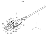
- Note that, in the description of the optical connector unit, a direction in which the optical fiber of each of the optical connectors is referred to as an “optical axis direction” (X direction of
FIG. 1 ), a direction in which the pair of optical connectors are aligned in parallel is referred to as a “width direction” (Y direction ofFIG. 1 ), and a direction orthogonal to the width direction and the optical axis direction is referred to as an “up-down direction” (Z direction ofFIG. 1 ). However, those directions are defined for convenience of description, and not intended to limit an aspect of usage of the optical connector unit. - In this way, in the optical connector unit of the present invention, the locking lever extending obliquely upward toward the proximal end side is provided in the top surface of the housing of each of the optical connectors, and the operation lever extending obliquely upward toward the leading end side and including the pressing part located above the locking lever is provided on the top surface of the main body portion of the boot. According to the optical connector unit, the pair of optical connectors can be easily exchanged in position. More specifically, the boot is detached from the holder (see
FIG. 5 ), the optical connectors are each reversed upside down relative to the holder while the boot is reversed upside down relative to the holder (seeFIG. 6 ), and then the boot is placed back over the holder (seeFIG. 7 ), thereby being capable of exchanging the positions of the pair of optical connectors under a state in which the locking levers and the operation lever are in the same orientation. - In the optical connector unit as described above, the pair of optical connectors are in a state in which the locking levers are in the same orientation (upward orientation). However, when the optical connectors are rotated relative to the holder, orientations of the pair of locking levers may be displaced and the optical connector unit may not be able to be mounted to the optical adapter. For example, if the holder includes a rotation restricting portion for restricting rotation of the optical connectors, it is possible to keep the locking levers in the same orientation. However, in this case, when reversing the pair of optical connectors upside down relative to the holder as described above, each of the optical connectors needs to be once detached from the holder. Work of detaching the optical connectors from the holder in this way is troublesome and may cause the damages of the optical fibers during the detaching work.
- Thus, if the boot includes a rotation restricting portion for restricting the rotation of the optical connectors relative to the holder, it is unnecessary to provide the rotation restricting portion on the holder. As a result, the optical connectors can be rotated relative to the holder by detaching the boot from the holder and disengaging the rotation restricting portion and the locking levers (see
FIG. 5 ). Therefore, the optical connectors each can be easily reversed upside down while being mounted in the holder. For example, the operation lever may include interlocking portions which engage with the locking lever on both sides in the width direction, and the interlocking portions may function as the rotation restricting portion. - As described above, in contrast to an operation lever which has been provided in a holder in a conventional product, according to the present invention, the operation lever is provided in a boot, thereby being capable of easily exchanging positions of a pair of optical connectors. As a result, even when the pair of optical connectors are reversely mounted by mistake during assembly, the optical connectors can be exchanged back into correct positions in use, and hence the optical connector unit and a duplex cable can be used without waste.
-
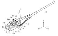
FIG. 1A perspective view illustrating an optical connector unit according to an embodiment of the present invention. -
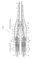
FIG. 2 A cross-sectional view illustrating the optical connector unit. -
FIG. 3A A perspective view illustrating a holder of the optical connector unit. -
FIG. 3B A perspective view illustrating the holder. -
FIG. 3C A plan view illustrating the holder. -
FIG. 3D A side view illustrating the holder seen from the direction D ofFIG. 3C . -
FIG. 3E A side view illustrating the holder seen from the direction E ofFIG. 3C . -
FIG. 3F A cross-sectional view illustrating the holder. -
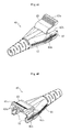
FIG. 4A A perspective view illustrating a boot of the optical connector unit. -
FIG. 4B A perspective view illustrating the boot. -
FIG. 4C A plan view illustrating the boot. -
FIG. 4D A side view illustrating the boot seen from the direction D of theFIG. 4C . -
FIG. 4E A side view illustrating the boot seen from the direction E of theFIG. 4C . -
FIG. 5 A perspective view illustrating a step of exchanging a pair of optical connectors of the optical connector unit (a state in which the boot is detached). -
FIG. 6 A perspective view illustrating a step of exchanging the pair of optical connectors of the optical connector unit (a state in which the optical connectors and the boot are reversed upside down). -
FIG. 7 A perspective view illustrating a step of exchanging the pair of optical connectors of the optical connector unit (a state in which the boot is refitted). -
FIG. 8 A cross-sectional view illustrating a duplex cable having a spectacles-like cross-sectional shape. -
FIG. 9 A plan view schematically illustrating a conventional optical connector unit. -
FIG. 10 A perspective view illustrating a conventional optical connector unit. -
FIG. 11 Across-sectional view illustrating a duplex cable having a substantially circular cross-sectional shape. -
FIG. 12A A side view (front view) illustrating the optical connector unit ofFIG. 10 . -
FIG. 12B A side view (front view) illustrating the pair of optical connectors ofFIG. 12A , each of which is reversed upside down. -
FIG. 12C Aside view (front view) illustrating the entire optical connector unit of theFIG. 12B reversed upside down. - Hereinafter, an embodiment of the present invention is described with reference to the drawings.
- As illustrated in
FIG. 1 , anoptical connector unit 1 according to the embodiment of the present invention is fixed to a leading end of aduplex cable 10. Theduplex cable 10 includes a pair of optical fibers therein. In this embodiment, as illustrated inFIG. 2 , theduplex cable 10 includes a pair ofbare fibers tube 13 which covers outer peripheries of the pair ofbare fibers reinforcement fiber 14 filled between thebare fibers tube 13. Theduplex cable 10 has a substantially circular cross-sectional shape, similarly to theduplex cable 201 illustrated inFIG. 11 . - The
optical connector unit 1 is mounted into a mounting hole of an optical adapter (not shown). Theoptical connector unit 1 mainly includes an inputoptical connector 20 a, an outputoptical connector 20 b, aholder 30, and aboot 40. Note that, in the illustrated example, a right-left direction ofFIG. 2 is referred to as an “optical axis direction”, an up-down direction ofFIG. 2 is referred to as a “width direction”, and a direction orthogonal to the drawing sheet ofFIG. 2 is referred to as an “up-down direction”. Further, an optical adapter side in the optical axis direction (left side ofFIG. 2 ) is referred to as a leading end side, and the opposite side thereof (right side ofFIG. 2 ) is referred to as a proximal end side. - The
optical connectors bare fibers FIG. 2 ). The inputoptical connector 20 a and the outputoptical connector 20 b have a similar configuration. Theoptical connectors ferrule 21 fixed to the leading end of thebare fiber flange part 22 fixed at a proximal end portion of theferrule 21, ahousing 23 holding theferrule 21 within its inner periphery, a lockinglever 24 provided in a top surface of thehousing 23, and acap 25 provided in a proximal end portion of thehousing 23. - The
ferrule 21 includes an insertion hole formed therein, for inserting the optical fiber (not shown) of thebare fiber spring 26 is mounted in a compressed state in the optical axis direction between theflange part 22 and thecap 25. Thespring 26 applies an elastic force to bias theferrule 21 to the leading end side. Thecap 25 includes anannular groove 25 a formed in its outer peripheral surface. - As illustrated in
FIG. 1 , thehousing 23 has a substantially rectangular parallelepiped shape, and includes a through-hole formed therein in the optical axis direction. Theferrule 21, theflange part 22, thespring 26, and thebare fiber - The locking
lever 24 extends obliquely upward from the top surface of thehousing 23 toward the proximal end side and is elastic in the up-down direction. In this embodiment, the lockinglever 24 and thehousing 23 are integrally molded. The lockinglever 24 includes a interlockingportion 24 a in its middle portion. The interlockingportion 24 a is engaged, in the optical axis direction, with a locking groove (not shown) provided in the optical adapter, to thereby prevent theoptical connector - As illustrated in
FIGS. 3A and 3B , theholder 30 includes, amain body portion 31 and acable fixing portion 32 protruding from themain body portion 31 toward the proximal end side. Theholder 30 has a symmetrical shape in the up-down direction and the right-left direction. Themain body portion 31 has a substantially rectangular shape in plan view, and is provided withconnector fixing portions optical connectors FIGS. 3B and 3D ). Theconnector fixing portions main body portion 31. Theannular grooves 25 a of thecaps 25 of theoptical connectors connector fixing portions FIG. 2 ). Theconnector fixing portions openings 31 a 1, 31b 1, which have a dimension L in the up-down direction (seeFIG. 3D ) set to be slightly smaller than an outer diameter of theannular grooves 25 a. Further, theconnector fixing portions annular grooves 25 a. - The
optical connectors holder 30 as follows. First, theannular grooves 25 a of theoptical connectors openings 31 a 1, 31b 1 from the outside in the width direction, to thereby elastically expand theopenings 31 a 1, 31b 1 up and down. When theannular grooves 25 a reach theconnector fixing portions openings 31 a 1, 31b 1 elastically recover their original shapes to complete the fitting. At this time, theannular grooves 25 a and theconnector fixing portions optical connectors holder 30. Further, theoptical connectors holder 30 due to the fact that theopenings 31 a 1, 31b 1 of theconnector fixing portions annular grooves 25 a. Further, theoptical connectors holder 30 due to the fact that theconnector fixing portions annular grooves 25 a. - The
main body portion 31 is provided withprotrusions 31 c on both side surfaces in the width direction, and recessedportions 31 d are formed on the leading end side of theprotrusions 31 c (seeFIGS. 3A to 3C ). In the illustrated example, on each side surface of themain body portion 31, there are provided a pair ofprotrusions portions - The
cable fixing portion 32 has a substantially cylindrical shape, and includes guidegrooves bare fibers 11, 12 (seeFIGS. 3A and 3E ). Theguide grooves FIG. 3F ). - As illustrated in
FIG. 2 , thebare fibers guide grooves cable fixing portion 32 of theholder 30. The outer periphery of thecable fixing portion 32 is covered by thereinforcement fiber 14. Acaulking member 33 is placed over the outer periphery of thecable fixing portion 32 and thereinforcement fiber 14, and the outer periphery of thecaulking member 33 is fixedly caulked, thereby fixing theduplex cable 10 to theholder 30. In this way, thereinforcement fiber 14 of theduplex cable 10 is fixed to thecable fixing portion 32 of theholder 30. Thus, even when theduplex cable 10 is subjected to a tension, the tension can be borne by thereinforcement fiber 14 and thecaulking member 33, and hence it is possible to avoid a risk of the tension acting directly on thebare fibers - The
boot 40 is formed of a flexible material (for example, elastomer). As illustrated inFIGS. 4A and 4B , theboot 40 integrally includes, a tubularmain body portion 41 which narrows toward the proximal end side, a pair of fixingportions 42 which extend from both ends in the width direction of a leading end portion of themain body portion 41, and anoperation lever 43 which is provided in a top surface of themain body portion 41. As illustrated inFIG. 2 , themain body portion 41 covers the outer periphery of theduplex cable 10 extending from thecable fixing portion 32 of theholder 30 to the proximal end side. The elastic force of theboot 40 prevents theduplex cable 10 from being sharply folded in the vicinity of the proximal end portion of thecable fixing portion 32, and hence it is possible to prevent the damages of the optical fibers in thebare fibers - The fixing
portions 42 each includefitting holes 42 a formed therein, for fitting theprotrusions 31 c of themain body portion 31 of the holder 30 (seeFIGS. 4A , 4B, and 4D). Further, the fixingportions 42 each include acutout 42 b formed therein on the leading end side of the fitting holes 42 a (seeFIG. 4C ). When theboot 40 is placed over theholder 30, theprotrusions 31 c of theholder 30 are fitted into the fitting holes 42 a of theboot 40, and theprotrusions 31 and the fitting holes 42 a engage with each other in the optical axis direction. Therefore, theholder 30 is prevented from coming off theboot 40. Further, thecutouts 42 b of theboot 40 and the recessedportions 31 d of theholder 30 cooperatively form gaps 50 (seeFIG. 1 ). Theprotrusions 31 c and the fitting holes 42 a can be disengaged from each other by inserting a jig or the like (not shown) in thegaps 50 so as to elastically deform the fixingportions 42 of theboot 40 outward in the width direction. Therefore, it is possible to easily separate theboot 40 and theholder 30 from each other. - As illustrated in
FIG. 4D , theoperation lever 43 extends obliquely upward from the top surface of themain body portion 41 toward the leading end side. Theoperation lever 43 includes a leading end portion which is provided above proximal end portions of the locking levers 24, 24 of the pair ofoptical connectors FIG. 1 ). The leading end portion functions as apressing part 43 a for downwardly pressing the pair of lockinglevers operation lever 43 is downwardly pressed to be elastically deformed, thepressing part 43 a of theoperation lever 43 downwardly presses the proximal end portions of the pair of lockinglevers portions optical connector unit 1 can be detached from the optical adapter. Note that, theboot 40 may have a mark, a letter, and the like on its surface (for example, on a top surface of the operation lever 42) for explicitly indicating which one of the pair ofoptical connectors - The
boot 40 is provided with a rotation restricting portion for restricting rotation of theoptical connectors holder 30. In this embodiment, theoperation lever 43 is provided with interlockingportions 43 b which engage with the locking levers 24 in the width direction, and the interlockingportions 42 b function as the rotation restricting portion. Specifically, as illustrated inFIGS. 4B and 4E , there are provided a plurality of (in the illustrated example, four) interlockingportions 43 b downwardly protruding from the leading end portion (pressingpart 43 a) of theoperation lever 43. The proximal end portion of the lockinglever 24 is fitted between a pair of interlockingportions portions 43 b and the lockinglever 24 engage with each other in a rotational direction, to thereby restrict the rotation of the lockinglever 24, resulting in restriction of the rotation of each of theoptical connectors holder 30. - In the
optical connector unit 1 having the configuration described above, theoptical connectors optical connectors FIGS. 5 to 7 . - In the optical connector unit into which the pair of
optical connectors FIG. 1 ), first, as illustrated inFIG. 5 , theboot 40 is detached from theholder 30. Specifically, the jig or the like is inserted into the gaps 50 (seeFIG. 1 ), which are formed between theboot 40 and theholder 30, so as to elastically deform the fixingportions 42 of theboot 40 outward in the width direction, thereby causing theprotrusions 31 c of theholder 30 and the fitting holes 42 a of theboot 40 to be disengaged from each other. In this state, theboot 40 is retracted to the proximal end side (see an arrow ofFIG. 5 ), thereby separating theboot 40 and theholder 30 from each other. As a result, the interlockingportions 43 b of theoperation lever 43 of theboot 40 and the locking levers 24, 24 of theoptical connectors optical connectors holder 30. - Next, as illustrated in
FIG. 6 , theoptical connectors holder 30 so as to be reversed upside down. Along with this, theboot 40 is rotated relative to theholder 30 so as to be reversed upside down. Note that, instead of rotating theoptical connectors optical connectors holder 30 as described above, theoptical connectors holder 30 and reversed upside down, and then fitted back to theholder 30. However, in this case, detaching and fitting theoptical connectors optical connectors optical connectors holder 30 as described above. - In this state, as illustrated in
FIG. 7 , theboot 40 is placed over theholder 30, and theprotrusions 31 c of theholder 30 are fitted into the fitting holes 42 a of theboot 40. Then, the entireoptical connector unit 1 is reversed upside down, thereby enabling theoptical connectors FIG. 1 ). - Note that, in the exchanging work of the
optical connectors holder 30 is reversed upside down after the exchanging work. In this embodiment, theholder 30 has a vertically symmetrical shape, and hence theoptical connector unit 1 has the same shape before and after the exchanging work. Thus, theoptical connector unit 1 after the exchanging work can be fitted to the optical adapter without any problem. - The present invention is not limited to the above-mentioned embodiment. For example, in the above-mentioned embodiment, the
operation lever 43 is provided with the rotation restricting portion (interlockingportions 43 b) for restricting the rotation of theoptical connectors holder 30, but the present invention is not limited thereto. For example, the fixingportions 42 of theboot 40 may be extended to the leading end side so as to be held in contact with side surfaces on the outside in the width direction of theoptical connectors optical connectors - Alternatively, the
holder 30 may be provided with a rotation restricting portion. In this case, even under a state in which theboot 40 is detached from theholder 30, theoptical connectors optical connectors FIGS. 5 and 6 ) under a state in which theoptical connectors connector fixing portions holder 30. In contrast to this, in the above-mentioned embodiment, theboot 40 is provided with the rotation restricting portion. Thus, theoptical connectors optical connectors holder 30. - Further, in the above-mentioned embodiment, the
duplex cable 10 having a substantially circular cross-sectional shape (seeFIG. 11 ) is employed. However, this is not restrictive and a duplex cable having, for example, a spectacles-like cross-sectional shape (seeFIG. 8 ) may be employed. As described above, the duplex cable having a substantially circular cross-sectional shape is preferred because the cable can be twisted more smoothly and theoptical connector unit 1 can be rotated and fitted to the optical adapter more easily. -
- 1 optical connector unit duplex cable
- 11, 12 bare fiber
- 20 a (input) optical connector
- 20 b (output) optical connector
- 21 ferrule
- 22 flange part
- 30 housing
- 24 locking lever
- 25 cap
- 30 holder
- 31 main body portion
- 31 a, 31 b connector fixing portion
- 32 cable fixing portion
- 32 a, 32 b guide groove
- 40 boot
- 41 main body portion
- 42 fixing portion
- 43 operation lever
- 43 a pressing part
- 43 b interlocking portion (rotation restricting portion)
- 50 gap
Claims (3)
1. A duplex optical connector unit, which is fixed to a leading end of a duplex cable including a pair of optical fibers therein, comprising:
a pair of optical connectors, each of which includes a ferrule provided to a leading end of each of the pair of optical fibers, a housing for holding the ferrule, and a locking lever extending obliquely upward from a top surface of the housing toward a proximal end side, the pair of optical connectors each being provided at the leading end of each of the pair of optical fibers;
a holder, which includes connector fixing portions for fixing the pair of optical connectors, and a cable fixing portion for fixing the duplex cable; and
a boot, which includes a main body portion fitted to the holder and covering an outer periphery of the duplex cable, an operation lever extending obliquely upward from a top surface of the main body portion toward a leading end side, and a pressing part provided in the operation lever and located above the locking lever.
2. A duplex optical connector unit according to claim 1 , wherein the boot includes a rotation restricting portion for restricting rotation of the pair of optical connectors relative to the holder.
3. A duplex optical connector unit according to claim 2 , wherein the operation lever includes interlocking portions which engage with the locking lever on both sides in a width direction, the interlocking portions functioning as the rotation restricting portion.
Applications Claiming Priority (2)
| Application Number | Priority Date | Filing Date | Title |
|---|---|---|---|
| JP2010128967A JP4995305B2 (en) | 2010-06-04 | 2010-06-04 | 2-core optical connector unit |
| JP2010-128967 | 2010-06-04 |
Publications (1)
| Publication Number | Publication Date |
|---|---|
| US20110299814A1 true US20110299814A1 (en) | 2011-12-08 |
Family
ID=45064528
Family Applications (1)
| Application Number | Title | Priority Date | Filing Date |
|---|---|---|---|
| US13/116,287 Abandoned US20110299814A1 (en) | 2010-06-04 | 2011-05-26 | Duplex optical connector unit |
Country Status (2)
| Country | Link |
|---|---|
| US (1) | US20110299814A1 (en) |
| JP (1) | JP4995305B2 (en) |
Cited By (62)
| Publication number | Priority date | Publication date | Assignee | Title |
|---|---|---|---|---|
| CN103091793A (en) * | 2012-10-10 | 2013-05-08 | 富波有限公司 | Optical cable connector device, optical cable assembly and method for changing polarity of optical fiber |
| US8678669B2 (en) * | 2012-08-14 | 2014-03-25 | Alliance Fiber Optic Products Co., Ltd. | Reconfigurable polarity detachable connector assembly |
| US20140205257A1 (en) * | 2012-05-21 | 2014-07-24 | Advanced Fiber Products, LLC | Secure SC Optical Fiber Connector and Removal Tools |
| US20140209762A1 (en) * | 2013-01-29 | 2014-07-31 | Tyco Electronics Nederland Bv | Guiding Support And Kit For Terminating A Transmission Cable |
| CN104081236A (en) * | 2012-01-12 | 2014-10-01 | 3M创新有限公司 | Field mountable duplex optical fiber connector with mechanical splice elements |
| CN104950402A (en) * | 2015-05-06 | 2015-09-30 | 富波有限公司 | Optical fiber cable assembly |
| US9448370B2 (en) | 2012-02-20 | 2016-09-20 | Commscope Technologies Llc | Connector and connector assembly |
| CN105977701A (en) * | 2016-04-29 | 2016-09-28 | 中航光电科技股份有限公司 | Plug shell and plug using same |
| US20170205590A1 (en) * | 2014-11-27 | 2017-07-20 | Suncall Technologies(SZ) Co., Ltd. | Lucent Connector Typed Duplex Connector |
| EP3095000A4 (en) * | 2014-01-13 | 2017-09-06 | Tyco Electronics (Shanghai) Co. Ltd. | Fiber optic connector |
| US9761998B2 (en) | 2011-02-08 | 2017-09-12 | Commscope Technologies Llc | Release tab for an electrical connector and electrical connector comprising said release tab |
| US9825403B2 (en) | 2011-02-08 | 2017-11-21 | Commscope Technologies Llc | RJ type connector including a disengagement feature acting on the latch of the connector |
| US9829653B1 (en) * | 2016-09-12 | 2017-11-28 | Senko Advanced Components, Inc. | Optical connector and adapter system for a dual-ferrule connector |
| US10359577B2 (en) | 2017-06-28 | 2019-07-23 | Corning Research & Development Corporation | Multiports and optical connectors with rotationally discrete locking and keying features |
| US10379298B2 (en) | 2017-06-28 | 2019-08-13 | Corning Research & Development Corporation | Fiber optic connectors and multiport assemblies including retention features |
| US10641967B1 (en) | 2018-11-16 | 2020-05-05 | Corning Research & Development Corporation | Multiport assemblies including a modular adapter support array |
| US10768382B2 (en) | 2018-11-29 | 2020-09-08 | Corning Research & Development Corporation | Multiport assemblies including access apertures and a release tool |
| US10935736B2 (en) * | 2019-02-25 | 2021-03-02 | Leviton Manufacturing Co., Inc. | Rotary clip for duplex polarity change |
| US11061190B2 (en) * | 2017-07-14 | 2021-07-13 | Senko Advanced Components, Inc. | Small form factor fiber optic connector with multi-purpose boot assembly |
| US11187859B2 (en) | 2017-06-28 | 2021-11-30 | Corning Research & Development Corporation | Fiber optic connectors and methods of making the same |
| US11215767B2 (en) | 2017-06-07 | 2022-01-04 | Commscope Technologies Llc | Fiber optic adapter and cassette |
| US11294133B2 (en) | 2019-07-31 | 2022-04-05 | Corning Research & Development Corporation | Fiber optic networks using multiports and cable assemblies with cable-to-connector orientation |
| US11300746B2 (en) | 2017-06-28 | 2022-04-12 | Corning Research & Development Corporation | Fiber optic port module inserts, assemblies and methods of making the same |
| US11409056B2 (en) * | 2020-03-27 | 2022-08-09 | Afl Ig Llc | Optical fiber connectors and methods of connecting optical fibers |
| US11487073B2 (en) | 2019-09-30 | 2022-11-01 | Corning Research & Development Corporation | Cable input devices having an integrated locking feature and assemblies using the cable input devices |
| US11536921B2 (en) | 2020-02-11 | 2022-12-27 | Corning Research & Development Corporation | Fiber optic terminals having one or more loopback assemblies |
| US11555966B2 (en) | 2017-11-17 | 2023-01-17 | Commscope Technologies Llc | Fiber optic connector locking feature |
| US11573381B2 (en) | 2020-03-27 | 2023-02-07 | Afl Telecommunications Llc | Optical fiber connectors and methods of connecting optical fibers |
| US11604320B2 (en) | 2020-09-30 | 2023-03-14 | Corning Research & Development Corporation | Connector assemblies for telecommunication enclosures |
| US11650388B2 (en) | 2019-11-14 | 2023-05-16 | Corning Research & Development Corporation | Fiber optic networks having a self-supporting optical terminal and methods of installing the optical terminal |
| US11668890B2 (en) | 2017-06-28 | 2023-06-06 | Corning Research & Development Corporation | Multiports and other devices having optical connection ports with securing features and methods of making the same |
| US11686913B2 (en) | 2020-11-30 | 2023-06-27 | Corning Research & Development Corporation | Fiber optic cable assemblies and connector assemblies having a crimp ring and crimp body and methods of fabricating the same |
| EP4198590A3 (en) * | 2019-02-25 | 2023-08-02 | Sanwa Electronics USA Corporation | Reversible optical connectors |
| US11740413B1 (en) | 2022-03-02 | 2023-08-29 | Suncall America Inc. | Duplex optical connector with laterally repositionable connectors and pull boot release |
| USD1008971S1 (en) * | 2023-05-22 | 2023-12-26 | Chundi Liu | Connector |
| US11880076B2 (en) | 2020-11-30 | 2024-01-23 | Corning Research & Development Corporation | Fiber optic adapter assemblies including a conversion housing and a release housing |
| US11886010B2 (en) | 2019-10-07 | 2024-01-30 | Corning Research & Development Corporation | Fiber optic terminals and fiber optic networks having variable ratio couplers |
| US11927810B2 (en) | 2020-11-30 | 2024-03-12 | Corning Research & Development Corporation | Fiber optic adapter assemblies including a conversion housing and a release member |
| US11934017B2 (en) | 2021-03-02 | 2024-03-19 | Corning Research & Development Corporation | Polarity changeable optical connector |
| US11947167B2 (en) | 2021-05-26 | 2024-04-02 | Corning Research & Development Corporation | Fiber optic terminals and tools and methods for adjusting a split ratio of a fiber optic terminal |
| US11994722B2 (en) | 2020-11-30 | 2024-05-28 | Corning Research & Development Corporation | Fiber optic adapter assemblies including an adapter housing and a locking housing |
| US12019279B2 (en) | 2019-05-31 | 2024-06-25 | Corning Research & Development Corporation | Multiports and other devices having optical connection ports with sliding actuators and methods of making the same |
| US12044894B2 (en) | 2018-12-28 | 2024-07-23 | Corning Research & Development Corporation | Multiport assemblies including mounting features or dust plugs |
| US12158623B2 (en) | 2016-12-05 | 2024-12-03 | Senko Advanced Components, Inc. | Optical fiber connector |
| US12222559B2 (en) | 2016-01-15 | 2025-02-11 | Senko Advanced Components, Inc. | Narrow width adapters and connectors with pull tab release |
| US12228774B2 (en) | 2017-07-14 | 2025-02-18 | Senko Advanced Components, Inc. | Ultra-small form factor optical connector and adapter |
| US12235493B2 (en) | 2017-07-14 | 2025-02-25 | Senko Advanced Components, Inc. | Small form factor fiber optic connector with multi-purpose boot |
| US12248191B2 (en) | 2017-07-14 | 2025-03-11 | Senko Advanced Components, Inc. | Fiber optical connectors |
| US12259585B2 (en) | 2015-03-03 | 2025-03-25 | Senko Advanced Components, Inc. | Optical fiber connector with changeable polarity |
| US12271040B2 (en) | 2017-06-28 | 2025-04-08 | Corning Research & Development Corporation | Fiber optic extender ports, assemblies and methods of making the same |
| US12345925B2 (en) | 2020-05-29 | 2025-07-01 | Commscope Technologies Llc | Telecommunications connector with latch release mechanism |
| US12372727B2 (en) | 2020-10-30 | 2025-07-29 | Corning Research & Development Corporation | Female fiber optic connectors having a rocker latch arm and methods of making the same |
| US12399329B2 (en) | 2016-06-28 | 2025-08-26 | Senko Advanced Components, Inc. | Adapter system for multi-fiber mechanical transfer type ferrule |
| US12449612B2 (en) | 2019-03-28 | 2025-10-21 | Senko Advanced Components, Inc. | Fiber optic adapter assembly |
| US12455418B2 (en) | 2023-04-20 | 2025-10-28 | Corning Research & Development Corporation | Duplex fiber optic assembly with repositionable latch housing for polarity reversal, and related methods |
| US12461320B2 (en) | 2022-08-29 | 2025-11-04 | Corning Research & Development Corporation | Optical connector with rotatable boot and related methods |
| US12487423B2 (en) | 2018-11-29 | 2025-12-02 | Corning Research & Development Corporation | Multiports and other devices having optical connection ports with rotating actuators and methods of making the same |
| US12517306B2 (en) | 2020-06-29 | 2026-01-06 | Corning Research & Development Corporation | Terminals having a multi-fiber optical connection port that inhibits damage from single-fiber connectors |
| US12523821B2 (en) | 2021-04-08 | 2026-01-13 | Commscope Technologies Llc | Telecommunications connector with latch release mechanism |
| US12523824B2 (en) | 2019-10-18 | 2026-01-13 | Corning Research & Development Corporation | Terminals having optical connection ports with securing features providing stable retention forces and methods of making the same |
| US12560765B2 (en) | 2022-03-02 | 2026-02-24 | Corning Research & Development Corporation | Polarity changeable optical connector |
| US12571977B2 (en) | 2017-06-28 | 2026-03-10 | Corning Research & Development Corporation | Multiports and other devices having optical connection ports with securing features and methods of making the same |
Families Citing this family (3)
| Publication number | Priority date | Publication date | Assignee | Title |
|---|---|---|---|---|
| CN102520489B (en) * | 2012-01-11 | 2016-04-13 | 深圳日海通讯技术股份有限公司 | A kind of joints of optical fibre and assembly method thereof |
| JP5873760B2 (en) | 2012-05-25 | 2016-03-01 | 矢崎総業株式会社 | Optical connector |
| JP6363784B1 (en) * | 2017-07-31 | 2018-07-25 | 株式会社精工技研 | Optical connector plug and duplex optical connector plug |
Citations (5)
| Publication number | Priority date | Publication date | Assignee | Title |
|---|---|---|---|---|
| US5521997A (en) * | 1995-02-28 | 1996-05-28 | The Whitaker Corporation | Rotatably polarizing keying element for a polarized connector |
| US20020076164A1 (en) * | 2000-12-14 | 2002-06-20 | Childers Darrell R. | Trigger mechanism, optical cable connector including same, and method of assembling an optical cable connector |
| US20080226237A1 (en) * | 2007-03-15 | 2008-09-18 | O'riorden Stephen | Single boot for duplex fiber optic connectors |
| US20100220961A1 (en) * | 2009-02-27 | 2010-09-02 | De Jong Michael | Duplex Fiber Optic Assemblies Suitable for Polarity Reversal and Methods Therefor |
| US20110081113A1 (en) * | 2009-10-02 | 2011-04-07 | Jones Ashley W | Fiber Optic Connector Assembly and Methods Therefor |
Family Cites Families (3)
| Publication number | Priority date | Publication date | Assignee | Title |
|---|---|---|---|---|
| JP2005017419A (en) * | 2003-06-24 | 2005-01-20 | Nippon Telegr & Teleph Corp <Ntt> | Multi-fiber optical fiber connector and ferrule removal jig used therefor |
| JP4278148B2 (en) * | 2003-12-24 | 2009-06-10 | サンコール株式会社 | 2-core connector unit |
| JP4833802B2 (en) * | 2006-11-09 | 2011-12-07 | 三和電気工業株式会社 | Optical connector connection structure |
-
2010
- 2010-06-04 JP JP2010128967A patent/JP4995305B2/en active Active
-
2011
- 2011-05-26 US US13/116,287 patent/US20110299814A1/en not_active Abandoned
Patent Citations (5)
| Publication number | Priority date | Publication date | Assignee | Title |
|---|---|---|---|---|
| US5521997A (en) * | 1995-02-28 | 1996-05-28 | The Whitaker Corporation | Rotatably polarizing keying element for a polarized connector |
| US20020076164A1 (en) * | 2000-12-14 | 2002-06-20 | Childers Darrell R. | Trigger mechanism, optical cable connector including same, and method of assembling an optical cable connector |
| US20080226237A1 (en) * | 2007-03-15 | 2008-09-18 | O'riorden Stephen | Single boot for duplex fiber optic connectors |
| US20100220961A1 (en) * | 2009-02-27 | 2010-09-02 | De Jong Michael | Duplex Fiber Optic Assemblies Suitable for Polarity Reversal and Methods Therefor |
| US20110081113A1 (en) * | 2009-10-02 | 2011-04-07 | Jones Ashley W | Fiber Optic Connector Assembly and Methods Therefor |
Cited By (136)
| Publication number | Priority date | Publication date | Assignee | Title |
|---|---|---|---|---|
| US9761998B2 (en) | 2011-02-08 | 2017-09-12 | Commscope Technologies Llc | Release tab for an electrical connector and electrical connector comprising said release tab |
| US9991635B2 (en) | 2011-02-08 | 2018-06-05 | Commscope Technologies Llc | Release tab for an electrical connector and electrical connector comprising said release tab |
| US12088044B2 (en) | 2011-02-08 | 2024-09-10 | Commscope Technologies Llc | Connector including a disengagement feature |
| US9825403B2 (en) | 2011-02-08 | 2017-11-21 | Commscope Technologies Llc | RJ type connector including a disengagement feature acting on the latch of the connector |
| US11742617B2 (en) | 2011-02-08 | 2023-08-29 | Commscope Technologies Llc | RJ type connector including a disengagement feature acting on the latch of the connector |
| US11322889B2 (en) | 2011-02-08 | 2022-05-03 | Commscope Technologies Llc | RJ type connector including a disengagement feature acting on the latch of the connector |
| CN104081236A (en) * | 2012-01-12 | 2014-10-01 | 3M创新有限公司 | Field mountable duplex optical fiber connector with mechanical splice elements |
| US20150003790A1 (en) * | 2012-01-12 | 2015-01-01 | 3M Innovative Properties Company | Field mountable duplex optical fiber connector with mechanical splice elements |
| US9448370B2 (en) | 2012-02-20 | 2016-09-20 | Commscope Technologies Llc | Connector and connector assembly |
| US20140205257A1 (en) * | 2012-05-21 | 2014-07-24 | Advanced Fiber Products, LLC | Secure SC Optical Fiber Connector and Removal Tools |
| US9316791B2 (en) * | 2012-05-21 | 2016-04-19 | Optical Fiber Packaging Corporation | Secure SC optical fiber connector and removal tools |
| US8678669B2 (en) * | 2012-08-14 | 2014-03-25 | Alliance Fiber Optic Products Co., Ltd. | Reconfigurable polarity detachable connector assembly |
| CN103091793A (en) * | 2012-10-10 | 2013-05-08 | 富波有限公司 | Optical cable connector device, optical cable assembly and method for changing polarity of optical fiber |
| US9557495B2 (en) | 2012-10-10 | 2017-01-31 | Fibrefab Limited | Fibre optic connector device |
| GB2506884B (en) * | 2012-10-10 | 2017-04-12 | Fibrefab Ltd | Fibre optic connector device |
| WO2014057264A3 (en) * | 2012-10-10 | 2014-06-05 | Fibrefab Limited | Fibre optic connector device |
| GB2506884A (en) * | 2012-10-10 | 2014-04-16 | Fibrefab Ltd | Fibre optic connector device |
| US9407073B2 (en) * | 2013-01-29 | 2016-08-02 | Te Connectivity Nederland Bv | Guiding support and kit for terminating a transmission cable |
| US20140209762A1 (en) * | 2013-01-29 | 2014-07-31 | Tyco Electronics Nederland Bv | Guiding Support And Kit For Terminating A Transmission Cable |
| US10545296B2 (en) | 2014-01-13 | 2020-01-28 | Commscope Connectivity Uk Limited | Fiber optic connector |
| US12353026B2 (en) | 2014-01-13 | 2025-07-08 | Commscope Connectivity Uk Limited | Fiber optic connector |
| US11604319B2 (en) | 2014-01-13 | 2023-03-14 | Commscope Connectivity Uk Limited | Fiber optic connector |
| US11079556B2 (en) | 2014-01-13 | 2021-08-03 | Commscope Connectivity Uk Limited | Fiber optic connector |
| EP3095000A4 (en) * | 2014-01-13 | 2017-09-06 | Tyco Electronics (Shanghai) Co. Ltd. | Fiber optic connector |
| US10067301B2 (en) | 2014-01-13 | 2018-09-04 | Commscope Connectivity Uk Limited | Fiber optic connector |
| EP3907541A1 (en) * | 2014-01-13 | 2021-11-10 | CommScope Telecommunications (Shanghai) Co. Ltd. | Fiber optic connector |
| US20170205590A1 (en) * | 2014-11-27 | 2017-07-20 | Suncall Technologies(SZ) Co., Ltd. | Lucent Connector Typed Duplex Connector |
| US9869825B2 (en) * | 2014-11-27 | 2018-01-16 | Suncall Technologies (Sz) Co., Ltd. | Lucent connector typed duplex connector |
| US12313889B2 (en) | 2015-03-03 | 2025-05-27 | Senko Advanced Components, Inc. | Optical fiber connector with changeable polarity |
| US12259585B2 (en) | 2015-03-03 | 2025-03-25 | Senko Advanced Components, Inc. | Optical fiber connector with changeable polarity |
| US9971102B2 (en) * | 2015-05-06 | 2018-05-15 | Fibrefab Limited | Fibre optic cable assembly |
| CN104950402A (en) * | 2015-05-06 | 2015-09-30 | 富波有限公司 | Optical fiber cable assembly |
| US20160327756A1 (en) * | 2015-05-06 | 2016-11-10 | Fibrefab Limited | Fibre optic cable assembly |
| US12222559B2 (en) | 2016-01-15 | 2025-02-11 | Senko Advanced Components, Inc. | Narrow width adapters and connectors with pull tab release |
| CN105977701A (en) * | 2016-04-29 | 2016-09-28 | 中航光电科技股份有限公司 | Plug shell and plug using same |
| US12399329B2 (en) | 2016-06-28 | 2025-08-26 | Senko Advanced Components, Inc. | Adapter system for multi-fiber mechanical transfer type ferrule |
| US9829653B1 (en) * | 2016-09-12 | 2017-11-28 | Senko Advanced Components, Inc. | Optical connector and adapter system for a dual-ferrule connector |
| US12158623B2 (en) | 2016-12-05 | 2024-12-03 | Senko Advanced Components, Inc. | Optical fiber connector |
| US11650378B2 (en) | 2017-06-07 | 2023-05-16 | Commscope Technologies Llc | Fiber optic adapter and cassette |
| US11215767B2 (en) | 2017-06-07 | 2022-01-04 | Commscope Technologies Llc | Fiber optic adapter and cassette |
| US10809463B2 (en) | 2017-06-28 | 2020-10-20 | Corning Research & Development Corporation | Multiports and optical connectors with rotationally discrete locking and keying features |
| US11906792B2 (en) | 2017-06-28 | 2024-02-20 | Corning Research & Development Corporation | Compact fiber optic connectors having multiple connector footprints, along with cable assemblies and methods of making the same |
| US11215768B2 (en) | 2017-06-28 | 2022-01-04 | Corning Research & Development Corporation | Fiber optic connectors and connectorization employing adhesive admitting adapters |
| US11262509B2 (en) | 2017-06-28 | 2022-03-01 | Corning Research & Development Corporation | Compact fiber optic connectors having multiple connector footprints, along with cable assemblies and methods of making the same |
| US11287582B2 (en) | 2017-06-28 | 2022-03-29 | Corning Research & Development Corporation | Compact fiber optic connectors, cable assemblies and methods of making the same |
| US11287581B2 (en) | 2017-06-28 | 2022-03-29 | Corning Research & Development Corporation | Compact fiber optic connectors, cable assemblies and methods of making the same |
| US12571977B2 (en) | 2017-06-28 | 2026-03-10 | Corning Research & Development Corporation | Multiports and other devices having optical connection ports with securing features and methods of making the same |
| US11300735B2 (en) | 2017-06-28 | 2022-04-12 | Corning Research & Development Corporation | Compact fiber optic connectors having multiple connector footprints, along with cable assemblies and methods of making the same |
| US11300746B2 (en) | 2017-06-28 | 2022-04-12 | Corning Research & Development Corporation | Fiber optic port module inserts, assemblies and methods of making the same |
| US11307364B2 (en) | 2017-06-28 | 2022-04-19 | Corning Research & Development Corporation | Compact fiber optic connectors having multiple connector footprints, along with cable assemblies and methods of making the same |
| US12554075B2 (en) | 2017-06-28 | 2026-02-17 | Corning Research & Development Corporation | Multiports having connection ports with securing features that actuate flexures and methods of making the same |
| US11327247B2 (en) | 2017-06-28 | 2022-05-10 | Corning Optical Communications LLC | Multiports having connection ports formed in the shell and associated securing features |
| US12546955B2 (en) | 2017-06-28 | 2026-02-10 | Corning Research & Development Corporation | Compact fiber optic connectors having keying portions and locking features |
| US11409055B2 (en) | 2017-06-28 | 2022-08-09 | Corning Optical Communications LLC | Multiports having connection ports with associated securing features and methods of making the same |
| US12429655B2 (en) | 2017-06-28 | 2025-09-30 | Corning Optical Communications LLC | Multiports having connection ports with associated securing features and methods of making the same |
| US11415759B2 (en) | 2017-06-28 | 2022-08-16 | Corning Optical Communications LLC | Multiports having a connection port insert and methods of making the same |
| US11460646B2 (en) | 2017-06-28 | 2022-10-04 | Corning Research & Development Corporation | Fiber optic connectors and multiport assemblies including retention features |
| US10359577B2 (en) | 2017-06-28 | 2019-07-23 | Corning Research & Development Corporation | Multiports and optical connectors with rotationally discrete locking and keying features |
| US11487065B2 (en) | 2017-06-28 | 2022-11-01 | Corning Research & Development Corporation | Multiports and devices having a connector port with a rotating securing feature |
| US12379551B2 (en) | 2017-06-28 | 2025-08-05 | Corning Optical Communications LLC | Multiports having connection ports formed in the shell and associated securing features |
| US11493699B2 (en) | 2017-06-28 | 2022-11-08 | Corning Research & Development Corporation | Multifiber fiber optic connectors, cable assemblies and methods of making the same |
| US11493700B2 (en) | 2017-06-28 | 2022-11-08 | Corning Research & Development Corporation | Compact fiber optic connectors, cable assemblies and methods of making the same |
| US11531168B2 (en) | 2017-06-28 | 2022-12-20 | Corning Research & Development Corporation | Fiber optic connectors having a keying structure and methods of making the same |
| US12379552B2 (en) | 2017-06-28 | 2025-08-05 | Corning Research & Development Corporation | Compact fiber optic connectors, cable assemblies and methods of making the same |
| US11536913B2 (en) | 2017-06-28 | 2022-12-27 | Corning Research & Development Corporation | Fiber optic connectors and connectorization employing adhesive admitting adapters |
| US11543600B2 (en) | 2017-06-28 | 2023-01-03 | Corning Research & Development Corporation | Compact fiber optic connectors having multiple connector footprints, along with cable assemblies and methods of making the same |
| US10379298B2 (en) | 2017-06-28 | 2019-08-13 | Corning Research & Development Corporation | Fiber optic connectors and multiport assemblies including retention features |
| US12353024B2 (en) | 2017-06-28 | 2025-07-08 | Corning Research & Development Corporation | Multiports and optical connectors with rotationally discrete locking and keying features |
| US11579377B2 (en) | 2017-06-28 | 2023-02-14 | Corning Research & Development Corporation | Compact fiber optic connectors, cable assemblies and methods of making the same with alignment elements |
| US12353025B2 (en) | 2017-06-28 | 2025-07-08 | Corning Optical Communications LLC | Multiports having a connection port insert and methods of making the same |
| US10386584B2 (en) | 2017-06-28 | 2019-08-20 | Corning Research & Development Corporation | Optical connectors with locking and keying features for interfacing with multiports |
| US11624877B2 (en) | 2017-06-28 | 2023-04-11 | Corning Research & Development Corporation | Multiports having connection ports with securing features that actuate flexures and methods of making the same |
| US10802228B2 (en) | 2017-06-28 | 2020-10-13 | Corning Research & Development Corporation | Fiber optic connectors and multiport assemblies including retention features |
| US12298568B2 (en) | 2017-06-28 | 2025-05-13 | Corning Research & Development Corporation | Fiber optic connectors and multiport assemblies including retention features |
| US11656414B2 (en) | 2017-06-28 | 2023-05-23 | Corning Research & Development Corporation | Multiports and other devices having connection ports with securing features and methods of making the same |
| US11668890B2 (en) | 2017-06-28 | 2023-06-06 | Corning Research & Development Corporation | Multiports and other devices having optical connection ports with securing features and methods of making the same |
| US12276846B2 (en) | 2017-06-28 | 2025-04-15 | Corning Research & Development Corporation | Compact fiber optic connectors, cable assemblies and methods of making the same |
| US11703646B2 (en) | 2017-06-28 | 2023-07-18 | Corning Research & Development Corporation | Multiports and optical connectors with rotationally discrete locking and keying features |
| US12271040B2 (en) | 2017-06-28 | 2025-04-08 | Corning Research & Development Corporation | Fiber optic extender ports, assemblies and methods of making the same |
| US10429594B2 (en) * | 2017-06-28 | 2019-10-01 | Corning Research & Development Corporation | Multiport assemblies including retention features |
| US10429593B2 (en) | 2017-06-28 | 2019-10-01 | Corning Research & Development Corporation | Fiber optic connectors and connectorization employing adapter extensions and/or flexures |
| US11789214B2 (en) | 2017-06-28 | 2023-10-17 | Corning Research & Development Corporation | Multiports and other devices having keyed connection ports and securing features and methods of making the same |
| US12174432B2 (en) | 2017-06-28 | 2024-12-24 | Corning Research & Development Corporation | Fiber optic connectors and connectorization employing adhesive admitting adapters |
| US10605998B2 (en) | 2017-06-28 | 2020-03-31 | Corning Research & Development Corporation | Fiber optic connectors and connectorization employing adhesive admitting adapters |
| US12092878B2 (en) | 2017-06-28 | 2024-09-17 | Corning Research & Development Corporation | Fiber optic connectors having a keying structure and methods of making the same |
| US12013578B2 (en) | 2017-06-28 | 2024-06-18 | Corning Research & Development Corporation | Multifiber fiber optic connectors, cable assemblies and methods of making the same |
| US11886017B2 (en) | 2017-06-28 | 2024-01-30 | Corning Research & Development Corporation | Multiports and other devices having connection ports with securing features and methods of making the same |
| US11187859B2 (en) | 2017-06-28 | 2021-11-30 | Corning Research & Development Corporation | Fiber optic connectors and methods of making the same |
| US11914197B2 (en) | 2017-06-28 | 2024-02-27 | Corning Research & Development Corporation | Compact fiber optic connectors having multiple connector footprints, along with cable assemblies and methods of making the same |
| US11914198B2 (en) | 2017-06-28 | 2024-02-27 | Corning Research & Development Corporation | Compact fiber optic connectors having multiple connector footprints, along with cable assemblies and methods of making the same |
| US11966089B2 (en) | 2017-06-28 | 2024-04-23 | Corning Optical Communications, Llc | Multiports having connection ports formed in the shell and associated securing features |
| US11940656B2 (en) | 2017-06-28 | 2024-03-26 | Corning Research & Development Corporation | Compact fiber optic connectors, cable assemblies and methods of making the same |
| US12248191B2 (en) | 2017-07-14 | 2025-03-11 | Senko Advanced Components, Inc. | Fiber optical connectors |
| US11061190B2 (en) * | 2017-07-14 | 2021-07-13 | Senko Advanced Components, Inc. | Small form factor fiber optic connector with multi-purpose boot assembly |
| US12228774B2 (en) | 2017-07-14 | 2025-02-18 | Senko Advanced Components, Inc. | Ultra-small form factor optical connector and adapter |
| US12235493B2 (en) | 2017-07-14 | 2025-02-25 | Senko Advanced Components, Inc. | Small form factor fiber optic connector with multi-purpose boot |
| US11960126B2 (en) | 2017-11-17 | 2024-04-16 | Commscope Technologies Llc | Fiber optic connector locking feature |
| US11555966B2 (en) | 2017-11-17 | 2023-01-17 | Commscope Technologies Llc | Fiber optic connector locking feature |
| US10641967B1 (en) | 2018-11-16 | 2020-05-05 | Corning Research & Development Corporation | Multiport assemblies including a modular adapter support array |
| US10768382B2 (en) | 2018-11-29 | 2020-09-08 | Corning Research & Development Corporation | Multiport assemblies including access apertures and a release tool |
| US12487423B2 (en) | 2018-11-29 | 2025-12-02 | Corning Research & Development Corporation | Multiports and other devices having optical connection ports with rotating actuators and methods of making the same |
| US12044894B2 (en) | 2018-12-28 | 2024-07-23 | Corning Research & Development Corporation | Multiport assemblies including mounting features or dust plugs |
| US11360277B2 (en) | 2019-02-25 | 2022-06-14 | Leviton Manufacturing Co., Inc. | Rotary clip for duplex polarity change |
| EP4198590A3 (en) * | 2019-02-25 | 2023-08-02 | Sanwa Electronics USA Corporation | Reversible optical connectors |
| US11815722B2 (en) | 2019-02-25 | 2023-11-14 | Sanwa Electronics USA Corporation | Reversible optical connectors and associated devices, systems, and methods |
| US10935736B2 (en) * | 2019-02-25 | 2021-03-02 | Leviton Manufacturing Co., Inc. | Rotary clip for duplex polarity change |
| US12449612B2 (en) | 2019-03-28 | 2025-10-21 | Senko Advanced Components, Inc. | Fiber optic adapter assembly |
| US12019279B2 (en) | 2019-05-31 | 2024-06-25 | Corning Research & Development Corporation | Multiports and other devices having optical connection ports with sliding actuators and methods of making the same |
| US11294133B2 (en) | 2019-07-31 | 2022-04-05 | Corning Research & Development Corporation | Fiber optic networks using multiports and cable assemblies with cable-to-connector orientation |
| US11487073B2 (en) | 2019-09-30 | 2022-11-01 | Corning Research & Development Corporation | Cable input devices having an integrated locking feature and assemblies using the cable input devices |
| US11886010B2 (en) | 2019-10-07 | 2024-01-30 | Corning Research & Development Corporation | Fiber optic terminals and fiber optic networks having variable ratio couplers |
| US12523824B2 (en) | 2019-10-18 | 2026-01-13 | Corning Research & Development Corporation | Terminals having optical connection ports with securing features providing stable retention forces and methods of making the same |
| US11650388B2 (en) | 2019-11-14 | 2023-05-16 | Corning Research & Development Corporation | Fiber optic networks having a self-supporting optical terminal and methods of installing the optical terminal |
| US11536921B2 (en) | 2020-02-11 | 2022-12-27 | Corning Research & Development Corporation | Fiber optic terminals having one or more loopback assemblies |
| US11573381B2 (en) | 2020-03-27 | 2023-02-07 | Afl Telecommunications Llc | Optical fiber connectors and methods of connecting optical fibers |
| US11409056B2 (en) * | 2020-03-27 | 2022-08-09 | Afl Ig Llc | Optical fiber connectors and methods of connecting optical fibers |
| US12181721B2 (en) * | 2020-03-27 | 2024-12-31 | Afl Ig Llc | Optical fiber connectors and methods of connecting optical fibers |
| US20220350086A1 (en) * | 2020-03-27 | 2022-11-03 | Afl Ig Llc | Optical fiber connectors and methods of connecting optical fibers |
| US12345925B2 (en) | 2020-05-29 | 2025-07-01 | Commscope Technologies Llc | Telecommunications connector with latch release mechanism |
| US12517306B2 (en) | 2020-06-29 | 2026-01-06 | Corning Research & Development Corporation | Terminals having a multi-fiber optical connection port that inhibits damage from single-fiber connectors |
| US12019285B2 (en) | 2020-09-30 | 2024-06-25 | Corning Research & Development Corporation | Connector assemblies for telecommunication enclosures |
| US11604320B2 (en) | 2020-09-30 | 2023-03-14 | Corning Research & Development Corporation | Connector assemblies for telecommunication enclosures |
| US12372727B2 (en) | 2020-10-30 | 2025-07-29 | Corning Research & Development Corporation | Female fiber optic connectors having a rocker latch arm and methods of making the same |
| US12345927B2 (en) | 2020-11-30 | 2025-07-01 | Corning Research & Development Corporation | Fiber optic adapter assemblies including a conversion housing and a release housing |
| US11686913B2 (en) | 2020-11-30 | 2023-06-27 | Corning Research & Development Corporation | Fiber optic cable assemblies and connector assemblies having a crimp ring and crimp body and methods of fabricating the same |
| US11927810B2 (en) | 2020-11-30 | 2024-03-12 | Corning Research & Development Corporation | Fiber optic adapter assemblies including a conversion housing and a release member |
| US11880076B2 (en) | 2020-11-30 | 2024-01-23 | Corning Research & Development Corporation | Fiber optic adapter assemblies including a conversion housing and a release housing |
| US11994722B2 (en) | 2020-11-30 | 2024-05-28 | Corning Research & Development Corporation | Fiber optic adapter assemblies including an adapter housing and a locking housing |
| US11934017B2 (en) | 2021-03-02 | 2024-03-19 | Corning Research & Development Corporation | Polarity changeable optical connector |
| US12523821B2 (en) | 2021-04-08 | 2026-01-13 | Commscope Technologies Llc | Telecommunications connector with latch release mechanism |
| US11947167B2 (en) | 2021-05-26 | 2024-04-02 | Corning Research & Development Corporation | Fiber optic terminals and tools and methods for adjusting a split ratio of a fiber optic terminal |
| US11740413B1 (en) | 2022-03-02 | 2023-08-29 | Suncall America Inc. | Duplex optical connector with laterally repositionable connectors and pull boot release |
| US12560765B2 (en) | 2022-03-02 | 2026-02-24 | Corning Research & Development Corporation | Polarity changeable optical connector |
| US12461320B2 (en) | 2022-08-29 | 2025-11-04 | Corning Research & Development Corporation | Optical connector with rotatable boot and related methods |
| US12455418B2 (en) | 2023-04-20 | 2025-10-28 | Corning Research & Development Corporation | Duplex fiber optic assembly with repositionable latch housing for polarity reversal, and related methods |
| USD1008971S1 (en) * | 2023-05-22 | 2023-12-26 | Chundi Liu | Connector |
Also Published As
| Publication number | Publication date |
|---|---|
| JP2011253166A (en) | 2011-12-15 |
| JP4995305B2 (en) | 2012-08-08 |
Similar Documents
| Publication | Publication Date | Title |
|---|---|---|
| JP4995305B2 (en) | 2-core optical connector unit | |
| JP5669135B2 (en) | Enclosure assembly for connector, strain relief member, and sealing method | |
| CN108352649B (en) | Connector with a locking member | |
| US9739953B2 (en) | Optical connector | |
| JP5757219B2 (en) | Seal member | |
| US8608503B2 (en) | Connector guide member and electrical connector device having the same | |
| US8506174B2 (en) | Optical connector | |
| US7588373B1 (en) | Optical connector plug | |
| US9400357B2 (en) | Optical connector | |
| US7648289B2 (en) | Module having a handle to be operated to attach the module to a cage | |
| JP2012037652A (en) | Optical connector, removing jig, and removing structure of optical connector | |
| JP2019032432A (en) | Connector device and plug connector | |
| EP3790115B1 (en) | Connector and connecting method | |
| CN101939879A (en) | Electrical connectors with mechanical mating cycle limitation | |
| US9523827B2 (en) | Optical-electrical composite connector | |
| US20200144758A1 (en) | Connector | |
| US10129443B2 (en) | Imaging device | |
| CN104685728B (en) | Terminal sept | |
| JP2013160854A (en) | Optical connector | |
| JP4978484B2 (en) | Waterproof electronic equipment | |
| JP2018037365A (en) | connector | |
| EP2953209B1 (en) | Terminal attachment base, terminal, and audio apparatus | |
| JP6037850B2 (en) | Grommet | |
| US20140335713A1 (en) | Connector | |
| JP7591454B2 (en) | Cable Connectors |
Legal Events
| Date | Code | Title | Description |
|---|---|---|---|
| AS | Assignment |
Owner name: SUNCALL CORPORATION, JAPAN Free format text: ASSIGNMENT OF ASSIGNORS INTEREST;ASSIGNOR:NAKAGAWA, MASAYA;REEL/FRAME:026346/0056 Effective date: 20100617 |
|
| STCB | Information on status: application discontinuation |
Free format text: ABANDONED -- FAILURE TO RESPOND TO AN OFFICE ACTION |