US20110219829A1 - Linkage Lock - Google Patents
Linkage Lock Download PDFInfo
- Publication number
- US20110219829A1 US20110219829A1 US13/046,222 US201113046222A US2011219829A1 US 20110219829 A1 US20110219829 A1 US 20110219829A1 US 201113046222 A US201113046222 A US 201113046222A US 2011219829 A1 US2011219829 A1 US 2011219829A1
- Authority
- US
- United States
- Prior art keywords
- linkage lock
- links
- lock
- link
- linkage
- Prior art date
- Legal status (The legal status is an assumption and is not a legal conclusion. Google has not performed a legal analysis and makes no representation as to the accuracy of the status listed.)
- Granted
Links
- 239000000463 material Substances 0.000 claims description 8
- 230000007246 mechanism Effects 0.000 claims description 8
- 230000000295 complement effect Effects 0.000 claims description 6
- 239000002184 metal Substances 0.000 claims description 4
- 229910052751 metal Inorganic materials 0.000 claims description 4
- 238000012986 modification Methods 0.000 claims description 3
- 230000004048 modification Effects 0.000 claims description 3
- 230000001404 mediated effect Effects 0.000 claims 1
- 229920005615 natural polymer Polymers 0.000 claims 1
- 230000003068 static effect Effects 0.000 claims 1
- 229920001059 synthetic polymer Polymers 0.000 claims 1
- 239000002023 wood Substances 0.000 claims 1
- 239000007787 solid Substances 0.000 description 23
- 238000000034 method Methods 0.000 description 7
- 230000014759 maintenance of location Effects 0.000 description 5
- 238000010168 coupling process Methods 0.000 description 4
- 230000008878 coupling Effects 0.000 description 3
- 238000005859 coupling reaction Methods 0.000 description 3
- 238000003780 insertion Methods 0.000 description 3
- 230000037431 insertion Effects 0.000 description 3
- 229910000831 Steel Inorganic materials 0.000 description 2
- 229910045601 alloy Inorganic materials 0.000 description 2
- 239000000956 alloy Substances 0.000 description 2
- 229920003052 natural elastomer Polymers 0.000 description 2
- 229920001194 natural rubber Polymers 0.000 description 2
- 230000000717 retained effect Effects 0.000 description 2
- 239000010959 steel Substances 0.000 description 2
- 229920003051 synthetic elastomer Polymers 0.000 description 2
- 239000005061 synthetic rubber Substances 0.000 description 2
- 229910000760 Hardened steel Inorganic materials 0.000 description 1
- 239000000853 adhesive Substances 0.000 description 1
- 230000001070 adhesive effect Effects 0.000 description 1
- 229910052782 aluminium Inorganic materials 0.000 description 1
- XAGFODPZIPBFFR-UHFFFAOYSA-N aluminium Chemical compound [Al] XAGFODPZIPBFFR-UHFFFAOYSA-N 0.000 description 1
- 239000004744 fabric Substances 0.000 description 1
- 239000006260 foam Substances 0.000 description 1
- 239000010985 leather Substances 0.000 description 1
- 239000004033 plastic Substances 0.000 description 1
- 229920001296 polysiloxane Polymers 0.000 description 1
- 229920002379 silicone rubber Polymers 0.000 description 1
- 125000006850 spacer group Chemical group 0.000 description 1
- XLYOFNOQVPJJNP-UHFFFAOYSA-N water Substances O XLYOFNOQVPJJNP-UHFFFAOYSA-N 0.000 description 1
Images


Classifications
-
- E—FIXED CONSTRUCTIONS
- E05—LOCKS; KEYS; WINDOW OR DOOR FITTINGS; SAFES
- E05B—LOCKS; ACCESSORIES THEREFOR; HANDCUFFS
- E05B71/00—Locks specially adapted for bicycles, other than padlocks
-
- B—PERFORMING OPERATIONS; TRANSPORTING
- B62—LAND VEHICLES FOR TRAVELLING OTHERWISE THAN ON RAILS
- B62H—CYCLE STANDS; SUPPORTS OR HOLDERS FOR PARKING OR STORING CYCLES; APPLIANCES PREVENTING OR INDICATING UNAUTHORIZED USE OR THEFT OF CYCLES; LOCKS INTEGRAL WITH CYCLES; DEVICES FOR LEARNING TO RIDE CYCLES
- B62H5/00—Appliances preventing or indicating unauthorised use or theft of cycles; Locks integral with cycles
- B62H5/003—Appliances preventing or indicating unauthorised use or theft of cycles; Locks integral with cycles using chains or cables
-
- E—FIXED CONSTRUCTIONS
- E05—LOCKS; KEYS; WINDOW OR DOOR FITTINGS; SAFES
- E05B—LOCKS; ACCESSORIES THEREFOR; HANDCUFFS
- E05B67/00—Padlocks; Details thereof
- E05B67/003—Chain, wire or cable locks
-
- E—FIXED CONSTRUCTIONS
- E05—LOCKS; KEYS; WINDOW OR DOOR FITTINGS; SAFES
- E05B—LOCKS; ACCESSORIES THEREFOR; HANDCUFFS
- E05B37/00—Permutation or combination locks; Puzzle locks
- E05B37/0068—Permutation or combination locks; Puzzle locks in padlocks
-
- Y—GENERAL TAGGING OF NEW TECHNOLOGICAL DEVELOPMENTS; GENERAL TAGGING OF CROSS-SECTIONAL TECHNOLOGIES SPANNING OVER SEVERAL SECTIONS OF THE IPC; TECHNICAL SUBJECTS COVERED BY FORMER USPC CROSS-REFERENCE ART COLLECTIONS [XRACs] AND DIGESTS
- Y10—TECHNICAL SUBJECTS COVERED BY FORMER USPC
- Y10T—TECHNICAL SUBJECTS COVERED BY FORMER US CLASSIFICATION
- Y10T70/00—Locks
- Y10T70/40—Portable
- Y10T70/402—Fetters
- Y10T70/409—Shackles
-
- Y—GENERAL TAGGING OF NEW TECHNOLOGICAL DEVELOPMENTS; GENERAL TAGGING OF CROSS-SECTIONAL TECHNOLOGIES SPANNING OVER SEVERAL SECTIONS OF THE IPC; TECHNICAL SUBJECTS COVERED BY FORMER USPC CROSS-REFERENCE ART COLLECTIONS [XRACs] AND DIGESTS
- Y10—TECHNICAL SUBJECTS COVERED BY FORMER USPC
- Y10T—TECHNICAL SUBJECTS COVERED BY FORMER US CLASSIFICATION
- Y10T70/00—Locks
- Y10T70/40—Portable
- Y10T70/413—Padlocks
- Y10T70/417—Combination-controlled
- Y10T70/435—Flexible shackle
-
- Y—GENERAL TAGGING OF NEW TECHNOLOGICAL DEVELOPMENTS; GENERAL TAGGING OF CROSS-SECTIONAL TECHNOLOGIES SPANNING OVER SEVERAL SECTIONS OF THE IPC; TECHNICAL SUBJECTS COVERED BY FORMER USPC CROSS-REFERENCE ART COLLECTIONS [XRACs] AND DIGESTS
- Y10—TECHNICAL SUBJECTS COVERED BY FORMER USPC
- Y10T—TECHNICAL SUBJECTS COVERED BY FORMER US CLASSIFICATION
- Y10T70/00—Locks
- Y10T70/40—Portable
- Y10T70/413—Padlocks
- Y10T70/437—Key-controlled
- Y10T70/483—Flexible shackle
-
- Y—GENERAL TAGGING OF NEW TECHNOLOGICAL DEVELOPMENTS; GENERAL TAGGING OF CROSS-SECTIONAL TECHNOLOGIES SPANNING OVER SEVERAL SECTIONS OF THE IPC; TECHNICAL SUBJECTS COVERED BY FORMER USPC CROSS-REFERENCE ART COLLECTIONS [XRACs] AND DIGESTS
- Y10—TECHNICAL SUBJECTS COVERED BY FORMER USPC
- Y10T—TECHNICAL SUBJECTS COVERED BY FORMER US CLASSIFICATION
- Y10T70/00—Locks
- Y10T70/50—Special application
- Y10T70/5009—For portable articles
-
- Y—GENERAL TAGGING OF NEW TECHNOLOGICAL DEVELOPMENTS; GENERAL TAGGING OF CROSS-SECTIONAL TECHNOLOGIES SPANNING OVER SEVERAL SECTIONS OF THE IPC; TECHNICAL SUBJECTS COVERED BY FORMER USPC CROSS-REFERENCE ART COLLECTIONS [XRACs] AND DIGESTS
- Y10—TECHNICAL SUBJECTS COVERED BY FORMER USPC
- Y10T—TECHNICAL SUBJECTS COVERED BY FORMER US CLASSIFICATION
- Y10T70/00—Locks
- Y10T70/50—Special application
- Y10T70/5872—For cycles
Definitions
- the present disclosure relates generally to linkage locks and, more particularly, at least to a lock for transporting with bicycles and securing bicycles to an stationary object.
- Locking devices may be used to secure a bicycle or other mobile object to a stationary object to prevent theft.
- U or shackle locks typically consist of a U-shaped steel shackle that is removably coupled to a receiving lock cylinder.
- Cable locks are another common device used to secure bicycles and other mobile objects to stationary objects. Cable locks are available in a variety of lengths and diameters that can easily secure multiple components around objects of varied size. Cable locks have innate portability as they can be wrapped around almost any frame member and be attached to a bicycle with a bracket or clip.
- Another common locking device used to secure bicycles and other mobile devices to a stationary object is a chain lock, which uses hardened steel links connected by a high strength lock.
- a linkage lock is disclosed which according to certain embodiments may be used to fix a bicycle or other object such as a motorcycle, scooter, outdoor furniture, etc. to a stationary and immovable object such as a bicycle rack, sign pole, or tree to prevent theft or other unintended removal.
- a linkage lock includes at least a plurality of elongated links capable of being arranged in a substantially tubular configuration; wherein each link has a longitudinal axis extending therethrough and at least one pivot disposed at the ends thereof configured to allow rotation about an axis in substantially orthogonal relation to the longitudinal axis; wherein at least one link is configured to be separable from the remainder of the linkage lock.
- FIG. 1 shows a perspective view of an embodiment of the present disclosure in a first configuration.
- FIG. 2 a shows a perspective view of two solid links which form an assembly according to the embodiment of the present disclosure shown in FIG. 1 .
- FIG. 2 b shows a perspective view of two internal armatures of the solid links according to the embodiment of the present disclosure shown in FIG. 1 .
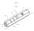
- FIG. 3 shows a perspective view of two separable links according to the embodiment of the present disclosure shown in FIG. 1 .
- FIG. 4 shows a perspective view of the embodiment of the present disclosure of FIG. 1 in a second configuration.
- FIG. 5 shows a perspective view of the embodiment of the present disclosure of FIG. 1 in a third configuration.
- FIG. 6 shows a perspective view of the embodiment of the present disclosure of FIG. 1 in a fourth configuration.
- FIG. 7 shows a side view of the embodiment of the present disclosure of FIG. 1 in the first configuration disposed about the top tube of a bicycle.
- FIG. 8 shows a side view of the embodiment of the present disclosure of FIG. 1 in the first configuration disposed in a bicycle water bottle cage.
- FIG. 9 shows a perspective view of the embodiment of the present disclosure of FIG. 1 in the fourth configuration disposed about the wheels of a bicycle and a post.
- FIG. 10 shows an embodiment of the present disclosure having magnets disposed in the links thereof.
- FIG. 11 shows an embodiment of the present disclosure configured to engage spokes of a wheel.
- FIG. 12 shows further embodiments of the present disclosure and the coupling thereof.
- FIG. 13 shows a further embodiment of the present disclosure.
- FIG. 14 shows a further embodiment of the present disclosure.
- FIG. 15 shows a further embodiment of the present disclosure.
- chiral and ‘chirality’ shall have their ordinary meaning in the art, namely one which describes a relationship between two shapes which (1) each lack an internal plane of symmetry and (2) are non-superimposable mirror images of one another. Chiral shapes include for instance human hands.
- Linkage lock 100 further includes at least a plurality of right-handed solid links 130 ( a , b), left-handed solid links 230 ( a , b), a right-handed separable link 140 and a left-handed separable link 240 pivotally coupled by rotational couplers 150 ( a ⁇ 1) [not shown] capable of being arranged in a substantially tubular configuration as shown in FIG. 1 .
- solid link assembly 330 includes a right-handed solid link 130 and a left-handed solid link 230 whose configuration and features are substantially chiral reflections of one another. Substantially chiral reflections of features disposed upon left-handed solid link 230 are represented by numerals 100 greater than their corresponding structures disposed upon right-handed solid link 130 .
- Right-handed link 130 is an elongated member composed of a rigid material including for instance plastic, wood, or metal.
- Right-handed solid link 130 has a first surface 131 and a second surface 132 having an angle ⁇ therebetween and a longitudinal axis L extending therethrough. According to the embodiment shown in the figures, ⁇ is 60 degrees.
- trough 133 disposed at an interior surface of ⁇ , as well as an exterior curve 134 disposed at an exterior surface of ⁇ .
- trough 133 comprises a soft or non-marking surface including for instance a silicone, natural or synthetic rubber, foam, leather, fabric, a portion, or multiple portions thereof.
- female portion 151 and male portion 152 have complementary threads disposed thereupon configured for pivotally coupling multiple right-handed solid links 130 and left-handed solid links 230 to one another.
- One of ordinary skill in the art will appreciate that the chiral relationship between right-handed link 130 and left-handed link 230 applies to the direction of the threads of their respective components as well. For instance, in embodiments where male portion 152 of a right-handed solid link 130 is right-hand threaded, corresponding male portion 252 of corresponding left-handed solid link 230 is left-hand threaded. Similarly, in embodiments where male portion 152 of right-handed solid link 130 is right-hand threaded, corresponding female portion 251 is also right-hand threaded.
- respective female portions and a male portions of couplers may be joined by complimentary bayonet mounts, press-fittings, snap-fittings, rivets, adhesives disposed thereupon or other suitable pivotable coupling methods known in the mechanical arts.
- bearing 153 disposed within male portion 152 configured to allow rotation of a coupler 150 and its respective link 130 or 140 about an axis X.
- bearings disposed within female portion 151 , or both male portion 152 and female portion 151 configured to allow rotation about axis X.
- Rigid armatures 135 and 235 are substantially chiral reflections of one another. Substantially chiral reflections of features disposed upon right-handed rigid armature 235 are represented by numerals 100 greater than their corresponding structures disposed upon left-handed rigid armature 135 .
- armature 135 there is an elongated right-handed armature 135 disposed within solid link 130 which provides operative support for male portion 152 and female portion 151 .
- armature 135 is composed of metal including for instance an alloy of steel, an alloy of aluminum, or other suitable metal known in the art.
- a right-handed separable link 140 and left-handed separable link 240 are shown.
- Right-handed separable link 140 and left-handed separable link 240 are substantially chiral reflections of one another. Substantially chiral reflections of features disposed upon right-handed separable link 240 are represented by numerals 100 greater than their corresponding structures disposed upon left-handed separable link 140 .
- separable link 140 includes all of the features of a solid link 130 which has been separated along a medial plane M defining male link portion 141 and female link portion 142 .
- a pin 143 extending from male link portion 141 in substantially parallel relation to axis L configured to be removably retained within a complementary recess 144 extending into female link portion 142 in substantially parallel relation to axis L.
- a retention groove 145 disposed upon the circumference of pin 143 configured to be received and retained within a complimentary locking mechanism [not shown] disposed within corresponding recess 144 .
- the locking mechanism is configured to temporarily retain pin 143 therewithin according to suitable locking methods known in the art including for instance a pin, a bar, a lever, or clasp configured to act upon retention groove 145 or a similar structure and thereby temporarily fix pin 143 within recess 144 .
- suitable locking methods known in the art including for instance a pin, a bar, a lever, or clasp configured to act upon retention groove 145 or a similar structure and thereby temporarily fix pin 143 within recess 144 .
- there is a detent disposed within recess 144 comprising a spring-loaded lever or other suitable structure known in the art which temporarily retains retention groove 145 thereagainst and provides tactile as well as acoustic feedback to an operator thereof.
- keyed tumbler 170 disposed within female link portion 142 of a separable link 140 .
- Keyed tumbler 170 is a keyed locking mechanism configured to engage or disengage the locking mechanism against retention groove 145 in order to securely and temporarily retain pin 143 within recess 144 .
- keyed tumbler 170 is identical to keyed tumbler 270 .
- grip portions 160 ( a - c ) disposed upon right-handed separable link 130 configured for an operator to grasp the links with said operator's hands.
- Grip portions 160 ( a - c ) may be composed of the same material and surface finish as the remainder of right-handed separable link 130 , of the same material as right-handed separable link 130 but having a modified surface finish configured to increase the frictional coefficient between grip portions 160 ( a - c ) and the hands of an operator (including for instance raised or indented portions), or of different material than that of right-handed separable link 130 (such as those with lower durometers and/or increased frictional coefficients, for instance, silicones, and natural or synthetic rubbers).
- a first ‘folded’ configuration of an embodiment of the present disclosure is shown wherein alternating right-handed solid links 140 and left-handed solid links 240 are coupled to one another as well as to right-handed separable link 140 and left-handed separable link 240 by joining respective complementary male portions 152 and female portions 251 or male portions 252 and female portions 151 of the links together.
- the joined links approximate an tubular member where respective troughs 133 and troughs 233 define an interior surface of a tube and respective exterior curves 134 and curves 234 define an exterior surface of a tube.
- FIG. 4 a second separated configuration of the embodiment of the present disclosure is shown wherein right-handed separable link 140 and left-handed separable link 240 have been separated into two complimentary portions.
- right-handed and left-solid handed links as well as their respective separable links 140 and 240 may be rotated by an operator about respective axes X of rotational couplers 150 ( a ⁇ 1). Rotation of links about aforementioned axes allows the device to be configured for instance into a third configuration as shown in FIG. 5 .
- the embodiment shown in the figures discloses a linkage lock having two separable links
- one of the ends achieved by the separable links namely to allow the links which comprise the linkage lock to be temporarily disconnected from one another
- at least one of the couplers 150 ( a ⁇ 1) may be configured to be temporarily separable according to methods known in the arts.
- the area of a link where a coupler 150 ( a ⁇ 1) is attached may be temporarily separable from the remainder of the link according to methods known in the arts.
- a linkage lock 100 is provided in a ‘folded-locked’ configuration as shown in FIG. 1 .
- the linkage lock may be stored for instance in the bottle cage of a bicycle as shown in FIG. 8 or with troughs 135 and 235 of right-handed links 130 ( a , b), left-handed solid links 230 ( a , b), right-handed separable link 140 , and left-handed separable link 240 abutting the top tube of a bicycle as shown in FIG. 9 .
- an operator inserts a complimentary key into tumbler 170 disposed within right-handed separable link 140 and rotates said key within tumbler 170 relative to linkage lock 100 , thereby disengaging the locking mechanism.
- This procedure is repeated for similar components disposed within left-handed separable link 240 thereby disengaging the locking mechanisms and configuring the linkage lock in a ‘folded-unlocked’ configuration.
- linkage lock 100 grasps opposing sides of linkage lock 100 with the female link portion 142 of right-handed separable link 140 and female link 242 of separable link 240 in one hand and male link portion 141 of separable link 140 and male link portion 241 of separable link 240 in the other.
- the operator applies opposing forces with their hands thereby separating the portions of the linkage lock into an ‘unfolded—unlocked’ configuration as shown in FIG. 6 .
- the links which comprise linkage lock 100 may be rotated by an operator relative one another about their respective couplers into configurations which such as that shown in FIGS. 5 and 9 .
- the links of linkage lock are configured to approximate a loop which encloses both the components of an item to be locked, including for instance a bicycle, and a fixed structure to be locked to, including for instance a post as shown in FIG. 9 .
- the operator may insert pins 143 and 243 of separable links 140 and 240 into corresponding recesses 144 and 244 of separable links 140 and 240 .
- the operator is tactilely notified of positive insertion by the retention of retaining grooves 145 and 245 within respective recesses 144 and 244 .
- the operator may then insert the key into tumblers 170 and 270 disposed on separable links 140 240 thereby engaging the locking mechanisms against retaining grooves 145 and 245 thereby temporarily fixing the item to be locked, including for instance a bicycle against a fixed structure, including for instance a post as shown in FIG. 9 .
- adjacent link arms of a linkage lock have complementary magnets disposed in the body thereof such that along a given point in the link(s) rotation, including for instance when the device is in a tubular configuration, the magnets urge the links towards a parallel configuration.
- FIG. 11 an embodiment of the present disclosure is shown, wherein there is a plurality of hooks 1000 disposed about the periphery of at least one link dimensioned to retain said link against the spoke(s) of a bicycle.
- FIG. 12 further embodiments of the present disclosure are shown wherein a number of methods of coupling links to one another are provided.
- FIG. 13 a further embodiment of the present disclosure is shown wherein there is a spacer which may be inserted along the interior face of an assembled linkage lock to accommodate different sizes of tubing on a bicycle frame.
- FIG. 14 a further embodiment of the present disclosure is shown, wherein consecutive links are deformed axially from one another in a chiral configuration thereby approximating a tube.
- links may be coupled together by means of a shackle lock.
Landscapes
- Engineering & Computer Science (AREA)
- Mechanical Engineering (AREA)
- Lock And Its Accessories (AREA)
Abstract
A linkage lock includes at least a plurality of elongated links capable of being arranged in a substantially tubular configuration; wherein each link has a longitudinal axis extending therethrough and at least one pivot disposed at the ends thereof configured to allow rotation about an axis in substantially orthogonal relation to the longitudinal axis; wherein at least one link is configured to be separable from the remainder of the linkage lock.
Description
- This filing claims priority to Provisional Patent Application No. 61/313,675 filed Mar. 12, 2010, which is incorporated by reference herein in its entirety.
- The present disclosure relates generally to linkage locks and, more particularly, at least to a lock for transporting with bicycles and securing bicycles to an stationary object.
- Locking devices may be used to secure a bicycle or other mobile object to a stationary object to prevent theft.
- U or shackle locks typically consist of a U-shaped steel shackle that is removably coupled to a receiving lock cylinder.
- Cable locks are another common device used to secure bicycles and other mobile objects to stationary objects. Cable locks are available in a variety of lengths and diameters that can easily secure multiple components around objects of varied size. Cable locks have innate portability as they can be wrapped around almost any frame member and be attached to a bicycle with a bracket or clip.
- Another common locking device used to secure bicycles and other mobile devices to a stationary object is a chain lock, which uses hardened steel links connected by a high strength lock.
- A linkage lock is disclosed which according to certain embodiments may be used to fix a bicycle or other object such as a motorcycle, scooter, outdoor furniture, etc. to a stationary and immovable object such as a bicycle rack, sign pole, or tree to prevent theft or other unintended removal.
- According to one embodiment of the present disclosure, a linkage lock includes at least a plurality of elongated links capable of being arranged in a substantially tubular configuration; wherein each link has a longitudinal axis extending therethrough and at least one pivot disposed at the ends thereof configured to allow rotation about an axis in substantially orthogonal relation to the longitudinal axis; wherein at least one link is configured to be separable from the remainder of the linkage lock.
- In the figures, which are not necessarily drawn to scale, like numerals describe substantially similar components throughout the several views. Letters after numbers represent iterations of components substantially similar to others bearing that numeral. The drawings illustrate generally, by way of example, but not by way of limitation, various embodiments discussed in the claims of the present document.
-
FIG. 1 shows a perspective view of an embodiment of the present disclosure in a first configuration. -
FIG. 2 a shows a perspective view of two solid links which form an assembly according to the embodiment of the present disclosure shown inFIG. 1 . -
FIG. 2 b shows a perspective view of two internal armatures of the solid links according to the embodiment of the present disclosure shown inFIG. 1 . -
FIG. 3 shows a perspective view of two separable links according to the embodiment of the present disclosure shown inFIG. 1 . -
FIG. 4 shows a perspective view of the embodiment of the present disclosure ofFIG. 1 in a second configuration. -
FIG. 5 shows a perspective view of the embodiment of the present disclosure ofFIG. 1 in a third configuration. -
FIG. 6 shows a perspective view of the embodiment of the present disclosure ofFIG. 1 in a fourth configuration. -
FIG. 7 shows a side view of the embodiment of the present disclosure ofFIG. 1 in the first configuration disposed about the top tube of a bicycle. -
FIG. 8 shows a side view of the embodiment of the present disclosure ofFIG. 1 in the first configuration disposed in a bicycle water bottle cage. -
FIG. 9 shows a perspective view of the embodiment of the present disclosure ofFIG. 1 in the fourth configuration disposed about the wheels of a bicycle and a post. -
FIG. 10 shows an embodiment of the present disclosure having magnets disposed in the links thereof. -
FIG. 11 shows an embodiment of the present disclosure configured to engage spokes of a wheel. -
FIG. 12 shows further embodiments of the present disclosure and the coupling thereof. -
FIG. 13 shows a further embodiment of the present disclosure. -
FIG. 14 shows a further embodiment of the present disclosure. -
FIG. 15 shows a further embodiment of the present disclosure. - Within the scope of the present disclosure, the terms ‘chiral’ and ‘chirality’ shall have their ordinary meaning in the art, namely one which describes a relationship between two shapes which (1) each lack an internal plane of symmetry and (2) are non-superimposable mirror images of one another. Chiral shapes include for instance human hands.
- With reference to
FIG. 1 , a linkage lock embodying features of the present disclosure is indicated generally by thenumeral 100.Linkage lock 100 further includes at least a plurality of right-handed solid links 130(a, b), left-handed solid links 230(a, b), a right-handedseparable link 140 and a left-handedseparable link 240 pivotally coupled by rotational couplers 150(a−1) [not shown] capable of being arranged in a substantially tubular configuration as shown inFIG. 1 . - With reference to
FIG. 2 a,solid link assembly 330 includes a right-handedsolid link 130 and a left-handedsolid link 230 whose configuration and features are substantially chiral reflections of one another. Substantially chiral reflections of features disposed upon left-handedsolid link 230 are represented bynumerals 100 greater than their corresponding structures disposed upon right-handedsolid link 130. - Right-
handed link 130 is an elongated member composed of a rigid material including for instance plastic, wood, or metal. Right-handedsolid link 130 has afirst surface 131 and asecond surface 132 having an angle θ therebetween and a longitudinal axis L extending therethrough. According to the embodiment shown in the figures, θ is 60 degrees. With continued reference toFIG. 2 a, there is afemale portion 151 of a rotational coupler 150(a−1) disposed uponsurface 131 of a first end ofsolid link 130 and amale portion 152 of a rotational coupler 150(a−1) disposed uponsurface 132 at an opposing second end ofsolid link 130. Further, there is atrough 133 disposed at an interior surface of θ, as well as anexterior curve 134 disposed at an exterior surface of θ. According to certain embodiments of the present disclosure,trough 133 comprises a soft or non-marking surface including for instance a silicone, natural or synthetic rubber, foam, leather, fabric, a portion, or multiple portions thereof. - With continued reference to
FIG. 2 a,female portion 151 andmale portion 152 have complementary threads disposed thereupon configured for pivotally coupling multiple right-handedsolid links 130 and left-handedsolid links 230 to one another. One of ordinary skill in the art will appreciate that the chiral relationship between right-handed link 130 and left-handed link 230 applies to the direction of the threads of their respective components as well. For instance, in embodiments wheremale portion 152 of a right-handedsolid link 130 is right-hand threaded, correspondingmale portion 252 of corresponding left-handedsolid link 230 is left-hand threaded. Similarly, in embodiments wheremale portion 152 of right-handedsolid link 130 is right-hand threaded, correspondingfemale portion 251 is also right-hand threaded. - According to further embodiments of the present disclosure not shown in the figures, respective female portions and a male portions of couplers may be joined by complimentary bayonet mounts, press-fittings, snap-fittings, rivets, adhesives disposed thereupon or other suitable pivotable coupling methods known in the mechanical arts.
- With continued reference to
FIG. 2 a, there is a bearing 153 [not shown] disposed withinmale portion 152 configured to allow rotation of a coupler 150 and itsrespective link female portion 151, or bothmale portion 152 andfemale portion 151 configured to allow rotation about axis X. According to further embodiments of the present disclosure, there are detents along the rotational path of bearing 153. - With reference to
FIG. 2 b, right-handedrigid armature 135 and left-handedrigid armature 235 are shown.Rigid armatures rigid armature 235 are represented bynumerals 100 greater than their corresponding structures disposed upon left-handedrigid armature 135. - According to certain embodiments of the present disclosure, there is an elongated right-
handed armature 135 disposed withinsolid link 130 which provides operative support formale portion 152 andfemale portion 151. According to the embodiment of the present disclosure shown in the figures,armature 135 is composed of metal including for instance an alloy of steel, an alloy of aluminum, or other suitable metal known in the art. - With reference to
FIG. 3 , a right-handedseparable link 140 and left-handedseparable link 240 are shown. Right-handedseparable link 140 and left-handedseparable link 240 are substantially chiral reflections of one another. Substantially chiral reflections of features disposed upon right-handedseparable link 240 are represented bynumerals 100 greater than their corresponding structures disposed upon left-handedseparable link 140. - According to the embodiment of the present disclosure shown in
FIG. 3 ,separable link 140 includes all of the features of asolid link 130 which has been separated along a medial plane M definingmale link portion 141 andfemale link portion 142. There is apin 143 extending frommale link portion 141 in substantially parallel relation to axis L configured to be removably retained within acomplementary recess 144 extending intofemale link portion 142 in substantially parallel relation to axis L. There is aretention groove 145 disposed upon the circumference ofpin 143 configured to be received and retained within a complimentary locking mechanism [not shown] disposed withincorresponding recess 144. The locking mechanism is configured to temporarily retainpin 143 therewithin according to suitable locking methods known in the art including for instance a pin, a bar, a lever, or clasp configured to act uponretention groove 145 or a similar structure and thereby temporarily fixpin 143 withinrecess 144. According to certain embodiments of the present disclosure, there is a detent disposed withinrecess 144 comprising a spring-loaded lever or other suitable structure known in the art which temporarily retainsretention groove 145 thereagainst and provides tactile as well as acoustic feedback to an operator thereof. - With continued reference to
FIGS. 3 and 1 , there is akeyed tumbler 170 disposed withinfemale link portion 142 of aseparable link 140.Keyed tumbler 170 is a keyed locking mechanism configured to engage or disengage the locking mechanism againstretention groove 145 in order to securely and temporarily retainpin 143 withinrecess 144. According to certain embodiments of the present disclosure, keyedtumbler 170 is identical tokeyed tumbler 270. - According to further embodiments of the present disclosure, including for instance those shown in
FIG. 1 , there are grip portions 160(a-c) disposed upon right-handed separable link 130 configured for an operator to grasp the links with said operator's hands. Grip portions 160(a-c) may be composed of the same material and surface finish as the remainder of right-handedseparable link 130, of the same material as right-handed separable link 130 but having a modified surface finish configured to increase the frictional coefficient between grip portions 160(a-c) and the hands of an operator (including for instance raised or indented portions), or of different material than that of right-handed separable link 130 (such as those with lower durometers and/or increased frictional coefficients, for instance, silicones, and natural or synthetic rubbers). - With returning reference to
FIG. 1 , a first ‘folded’ configuration of an embodiment of the present disclosure is shown wherein alternating right-handedsolid links 140 and left-handedsolid links 240 are coupled to one another as well as to right-handedseparable link 140 and left-handed separable link 240 by joining respective complementarymale portions 152 andfemale portions 251 ormale portions 252 andfemale portions 151 of the links together. In such a ‘folded’ configuration the joined links approximate an tubular member whererespective troughs 133 andtroughs 233 define an interior surface of a tube and respectiveexterior curves 134 andcurves 234 define an exterior surface of a tube. - With reference to
FIG. 4 , a second separated configuration of the embodiment of the present disclosure is shown wherein right-handedseparable link 140 and left-handed separable link 240 have been separated into two complimentary portions. In such a configuration right-handed and left-solid handed links as well as their respectiveseparable links FIG. 5 . - One of ordinary skill in the art will appreciate that although the embodiment shown in the figures discloses a linkage lock have six links with each link having equal 0 values of approximately 60 degrees, that there are embodiments within the scope of the present disclosure with as few as three links and as many as twenty links having corresponding 0 values which when the links are configured in a ‘closed’ orientation approximate a tube.
- One of ordinary skill in the art will further appreciate that although the embodiment shown in the figures discloses a linkage lock having two separable links, there are embodiments within the scope of the present disclosure wherein one of the ends achieved by the separable links, namely to allow the links which comprise the linkage lock to be temporarily disconnected from one another may be achieved with the use of other structures for their purpose. For instance, according to an embodiments of the present disclosure not shown in the figures, at least one of the couplers 150(a−1) may be configured to be temporarily separable according to methods known in the arts. According to further embodiments of the present disclosure not shown in the figures, the area of a link where a coupler 150(a−1) is attached may be temporarily separable from the remainder of the link according to methods known in the arts.
- One method of using the embodiment of the present disclosure shown in the figures will now be described. Initially, a
linkage lock 100 is provided in a ‘folded-locked’ configuration as shown inFIG. 1 . In a ‘folded-locked’ configuration, the linkage lock may be stored for instance in the bottle cage of a bicycle as shown inFIG. 8 or withtroughs separable link 140, and left-handed separable link 240 abutting the top tube of a bicycle as shown inFIG. 9 . Next, an operator inserts a complimentary key intotumbler 170 disposed within right-handedseparable link 140 and rotates said key withintumbler 170 relative tolinkage lock 100, thereby disengaging the locking mechanism. This procedure is repeated for similar components disposed within left-handed separable link 240 thereby disengaging the locking mechanisms and configuring the linkage lock in a ‘folded-unlocked’ configuration. - Next, an operator grasps opposing sides of
linkage lock 100 with thefemale link portion 142 of right-handedseparable link 140 andfemale link 242 ofseparable link 240 in one hand andmale link portion 141 ofseparable link 140 andmale link portion 241 ofseparable link 240 in the other. Next, the operator applies opposing forces with their hands thereby separating the portions of the linkage lock into an ‘unfolded—unlocked’ configuration as shown inFIG. 6 . When arranged in an ‘unfolded-unlocked’ configuration, the links which compriselinkage lock 100 may be rotated by an operator relative one another about their respective couplers into configurations which such as that shown inFIGS. 5 and 9 . In such configurations, the links of linkage lock are configured to approximate a loop which encloses both the components of an item to be locked, including for instance a bicycle, and a fixed structure to be locked to, including for instance a post as shown inFIG. 9 . Upon being suitably configured by an operator, the operator may insertpins separable links recesses separable links grooves respective recesses tumblers separable links 140 240 thereby engaging the locking mechanisms against retaininggrooves FIG. 9 . - One of ordinary skill in the art will appreciate that in order to disengage the lock, the aforementioned steps may be executed in reverse order.
- Referring now to
FIG. 10 , an embodiment of the present disclosure is shown, wherein adjacent link arms of a linkage lock have complementary magnets disposed in the body thereof such that along a given point in the link(s) rotation, including for instance when the device is in a tubular configuration, the magnets urge the links towards a parallel configuration. - Referring now to
FIG. 11 , an embodiment of the present disclosure is shown, wherein there is a plurality ofhooks 1000 disposed about the periphery of at least one link dimensioned to retain said link against the spoke(s) of a bicycle. - Referring now to
FIG. 12 , further embodiments of the present disclosure are shown wherein a number of methods of coupling links to one another are provided. - Referring now to
FIG. 13 , a further embodiment of the present disclosure is shown wherein there is a spacer which may be inserted along the interior face of an assembled linkage lock to accommodate different sizes of tubing on a bicycle frame. - Referring now to
FIG. 14 , a further embodiment of the present disclosure is shown, wherein consecutive links are deformed axially from one another in a chiral configuration thereby approximating a tube. - With reference to
FIG. 15 , an embodiment of the present disclosure is shown, wherein links may be coupled together by means of a shackle lock. - While the invention has been described herein in reference to specific aspects, features and illustrative embodiments of the invention and its method(s) of use, it will be appreciated that the utility of the invention is not thus limited, but rather extends to and encompasses numerous other variations, modifications and alternative embodiments, as will suggest themselves to those of ordinary skill in the field of the present invention, based on the disclosure herein. Correspondingly, the invention as hereinafter claimed is intended to be broadly construed and interpreted, as including all such variations, modifications and alternative embodiments, within its spirit and scope.
Claims (20)
1. A linkage lock comprising;
a plurality of elongated links capable of being arranged in a substantially annular configuration thereby approximating a tube;
wherein each link has a longitudinal axis extending therethrough and at least one pivot disposed at the ends thereof configured to allow rotation about an axis in substantially orthogonal relation to the longitudinal axis;
such that consecutive pivots are oriented at an angle theta relative to one another, and the sum of all of the thetas of all of the pivots which comprise the linkage lock add to 360 degrees;
wherein at least one link, pivot, or portion thereof is configured to be separable from the remainder of the linkage lock.
2. The linkage lock of claim 1 , wherein the features of the sequential links are substantially chiral reflections of one another.
3. The linkage lock of claim 1 , the pivot is selected from at least one of the following, a threaded rod and a complementary threaded recess, a sealed bearing, an open bearing, a post having a complimentary recess, a rivet, a press-fitting, or a snap-fitting.
4. The linkage lock of claim 1 , wherein there are mechanical detents in the rotational path of at least one of the pivots.
5. The linkage lock of claim 4 , wherein the mechanical detent provides at least one of the following functionalities, is a biasing member disposed within at least one of the pivots which urges its respective link(s) towards a detent, limits rotation, stalls rotation, or provides resistance.
6. The linkage lock of claim 1 , wherein the link, pivot, or portion thereof that is separable from the remainder of the linkage lock is configured to pivot away from the remainder of the linkage lock when so separated.
7. The linkage lock of claim 1 , where there are two separable links, pivots, or portions thereof which may be separated from the remainder of the assembly by translating such along the longitudinal axis.
8. The linkage lock of claim 1 , wherein the engagement of the separable link to the remainder of the assembly is mediated by a locking mechanism selected from at least one of the following, a keyed tumbler, a combination lock whose combination is encoded by a single disc, a combination lock whose combination is encoded by multiple disks, a combination lock whose combination is encoded by means of a keypad, or an electronic lock.
9. The linkage lock of claim 1 , wherein there is a soft or non-marring material disposed upon a portion of the outer surface of the assembled tube.
10. The linkage lock of claim 1 , wherein there is a soft or non-marring material disposed upon a portion of the inner surface of the assembled tube.
11. The linkage lock of claim 1 , wherein a portion of the exterior of the assembled tube is modified for improved gripping by the hand of a user, said modification may include, but is not limited to a single recess, a pattern of recesses, a single emboss, a pattern of embosses, a portion of material having a greater coefficient of static friction with skin than that of the remainder of the assembly, or a combination thereof.
12. The linkage lock of claim 1 , wherein the inner shape of the assembled tube is dimensioned to substantially complementorily engage a tube of a bicycle frame.
13. The linkage lock of claim 1 , wherein the outer shape of the assembled tube is dimensioned to substantially complementorily engage a bicycle water-bottle cage.
14. The linkage lock of claim 1 , where, the links are composed of a rigid material selected from at least one of wood, metal, natural polymers, synthetic polymers.
15. The linkage lock of claim 1 , wherein the total number of links is within the range of 4 to 10.
16. The linkage lock of claim 1 , wherein there are complementary magnets disposed within adjacent links configured to provide a temporary fixation thereof along a given point in the rotational path of said links.
17. The linkage lock of claim 1 , wherein the length of one or more pivot is adjustable thereby defining a range of inner diameters of the tube.
18. The linkage lock of claim 1 , wherein the at least one of the links may be temporarily separated along its longitudinal axis.
19. The linkage lock of claim 1 , wherein the exterior of at least one of the links has portions removed therefrom configured to temporarily engage the spokes of a bicycle.
20. The linkage lock of claim 1 , wherein two of the links may be disconnected from the remainder of the assembled linkage lock, thereby defining two distinct parts.
Priority Applications (1)
| Application Number | Priority Date | Filing Date | Title |
|---|---|---|---|
| US13/046,222 US8555682B2 (en) | 2010-03-12 | 2011-03-11 | Linkage lock |
Applications Claiming Priority (2)
| Application Number | Priority Date | Filing Date | Title |
|---|---|---|---|
| US31367510P | 2010-03-12 | 2010-03-12 | |
| US13/046,222 US8555682B2 (en) | 2010-03-12 | 2011-03-11 | Linkage lock |
Publications (2)
| Publication Number | Publication Date |
|---|---|
| US20110219829A1 true US20110219829A1 (en) | 2011-09-15 |
| US8555682B2 US8555682B2 (en) | 2013-10-15 |
Family
ID=44558643
Family Applications (1)
| Application Number | Title | Priority Date | Filing Date |
|---|---|---|---|
| US13/046,222 Expired - Fee Related US8555682B2 (en) | 2010-03-12 | 2011-03-11 | Linkage lock |
Country Status (1)
| Country | Link |
|---|---|
| US (1) | US8555682B2 (en) |
Cited By (9)
| Publication number | Priority date | Publication date | Assignee | Title |
|---|---|---|---|---|
| US20120151973A1 (en) * | 2010-12-20 | 2012-06-21 | Sinox Co., Ltd. | Linkage Lock |
| WO2013050728A1 (en) * | 2011-10-05 | 2013-04-11 | Patrick Elson | Cycle accessory |
| WO2014035952A1 (en) * | 2012-08-28 | 2014-03-06 | Master Lock Company Llc. | Locking arrangements |
| US20150013399A1 (en) * | 2013-06-10 | 2015-01-15 | Allen C Young | Lock with independent removable shackles for increased portability |
| EP2987710A3 (en) * | 2014-08-08 | 2016-03-02 | Trelock GmbH | Universal support |
| US20170120977A1 (en) * | 2015-10-30 | 2017-05-04 | Lu Ipd, Llc | Folding anti-theft device |
| WO2020055891A1 (en) * | 2018-09-11 | 2020-03-19 | Lobster Lock, Llc | Locking device |
| US11377876B2 (en) * | 2019-01-28 | 2022-07-05 | Ino Vision Ltd. | Magnetic keeper for bicycle lock element |
| CN114704160A (en) * | 2022-03-31 | 2022-07-05 | 海南电网有限责任公司万宁供电局 | Novel entrance guard management tool of transformer substation |
Families Citing this family (9)
| Publication number | Priority date | Publication date | Assignee | Title |
|---|---|---|---|---|
| US8939000B2 (en) * | 2011-06-13 | 2015-01-27 | David Mendyk | Seat post bicycle lock |
| US20150082843A1 (en) * | 2013-09-26 | 2015-03-26 | Ghostpost, LLC | Integrated seatpost bicycle lock |
| USD736593S1 (en) * | 2014-08-14 | 2015-08-18 | Safe Doc, L.L.C. | Adjustable chain latch |
| USD768462S1 (en) * | 2015-07-01 | 2016-10-11 | Euchner Gmbh & Co. Kg | Compact locking device |
| TWM519165U (en) * | 2015-08-18 | 2016-03-21 | 競泰股份有限公司 | Chain lock |
| TWM530338U (en) | 2015-09-25 | 2016-10-11 | 競泰股份有限公司 | Chain lock |
| USD769696S1 (en) * | 2015-10-02 | 2016-10-25 | Videx, Inc. | Electronic lock |
| USD865875S1 (en) * | 2018-08-28 | 2019-11-05 | Skip Transport, Inc. | Scooter with locking mechanism |
| DE102023108957A1 (en) * | 2023-04-06 | 2024-10-10 | ABUS August Bremicker Söhne Kommanditgesellschaft | Joint rod arrangement for a joint rod lock and joint rod lock |
Citations (34)
| Publication number | Priority date | Publication date | Assignee | Title |
|---|---|---|---|---|
| US2451100A (en) * | 1945-09-06 | 1948-10-12 | Lecompte Armand | Chain lock |
| US2655806A (en) * | 1950-01-24 | 1953-10-20 | Stiler Ted | Lock for thermostats |
| US3747379A (en) * | 1969-03-24 | 1973-07-24 | Peugeot & Renault | Electromagnetic safety latch systems |
| US3748876A (en) * | 1971-11-08 | 1973-07-31 | T Mathews | Bike security device |
| US3908414A (en) * | 1972-12-06 | 1975-09-30 | Stephen Lee Thorne | Bicycle locking harness |
| US3930389A (en) * | 1975-02-24 | 1976-01-06 | Robert Buikus | Lock and support device for fuel tank |
| US3959995A (en) * | 1975-06-09 | 1976-06-01 | Gerald William Fletcher | Ski lock |
| US4760718A (en) * | 1985-09-06 | 1988-08-02 | Kabushiki Kaisha Aiaishi | Wheel lock for vehicles |
| US4870843A (en) * | 1988-11-04 | 1989-10-03 | Lundberg Herbert J | Security system for cycles and the like |
| US4986095A (en) * | 1990-08-27 | 1991-01-22 | Chou Chao Jen | Retractable lock structure |
| US5018374A (en) * | 1989-09-06 | 1991-05-28 | Montano Venses J | Bicycle lock |
| USD347988S (en) * | 1993-01-05 | 1994-06-21 | Steve Thorne | Bicycle anti-theft assembly |
| US5325689A (en) * | 1991-09-19 | 1994-07-05 | Maureen Warner | Antitheft device for use on bicycles |
| USD349031S (en) * | 1992-02-24 | 1994-07-26 | Smith Dennis F | Bar linkage assembly for use with a padlock for securing a bicycle wheel |
| US5475993A (en) * | 1994-06-11 | 1995-12-19 | Kuo; Li-Tsao | Linkage lock device |
| US5487285A (en) * | 1992-05-26 | 1996-01-30 | Rene Leichel | Lock with rod-shaped elements |
| US5513508A (en) * | 1988-05-31 | 1996-05-07 | Paradigm Products, Inc. | Apparatus for inflating bicycle tires and other articles including a self contained lock structure |
| US5678435A (en) * | 1995-08-14 | 1997-10-21 | Hodson; James M. | Bicycle locking mechanism |
| US5732577A (en) * | 1993-08-11 | 1998-03-31 | Yamaha Hatsudoki Kabushiki Kaisha | Vehicle wheel lock |
| US5832753A (en) * | 1996-06-12 | 1998-11-10 | Nielsen; Peter N. | Lock assembly |
| US5913906A (en) * | 1996-03-07 | 1999-06-22 | I.P. Innovative Products S.R.L. | Folding anti-theft device |
| US5987936A (en) * | 1996-12-06 | 1999-11-23 | Hartman, Jr.; Charles William | Hinged securing member |
| US6012739A (en) * | 1998-02-18 | 2000-01-11 | Weiss Jonathan | Method and apparatus for securing a snowboard |
| US6044669A (en) * | 1998-05-08 | 2000-04-04 | Levi; Clark | Strap lock |
| US6125669A (en) * | 1999-08-25 | 2000-10-03 | Kryptonite Corporation | Portable security frame for portable articles |
| US6427499B1 (en) * | 2000-10-05 | 2002-08-06 | Jay S Derman | Portable equipment security device |
| US6820448B1 (en) * | 2004-03-30 | 2004-11-23 | Hui-Hua Hsieh | Bike and motorcycle padlock |
| US6862906B2 (en) * | 2001-11-09 | 2005-03-08 | Lindkjoelen Dan | Device for locking golf clubs in a golf bag |
| US7437898B2 (en) * | 2006-11-17 | 2008-10-21 | Su Wen-Chun | Lock device |
| US7481084B1 (en) * | 2008-04-08 | 2009-01-27 | Chun-Hsien Wu | Foldable lock structure |
| US7503194B2 (en) * | 2007-04-27 | 2009-03-17 | Mcneil Randy L | Multiple padlock lock system |
| US7581787B2 (en) * | 2007-06-17 | 2009-09-01 | Ino Vision Ltd. | Bicycle seat lock |
| US7624605B2 (en) * | 2006-06-01 | 2009-12-01 | Minin Vitali | Combined bicycle pedal and lock |
| US7712339B2 (en) * | 2007-07-27 | 2010-05-11 | Abus August Bremicker Soehne Kg | Joint rod lock |
-
2011
- 2011-03-11 US US13/046,222 patent/US8555682B2/en not_active Expired - Fee Related
Patent Citations (34)
| Publication number | Priority date | Publication date | Assignee | Title |
|---|---|---|---|---|
| US2451100A (en) * | 1945-09-06 | 1948-10-12 | Lecompte Armand | Chain lock |
| US2655806A (en) * | 1950-01-24 | 1953-10-20 | Stiler Ted | Lock for thermostats |
| US3747379A (en) * | 1969-03-24 | 1973-07-24 | Peugeot & Renault | Electromagnetic safety latch systems |
| US3748876A (en) * | 1971-11-08 | 1973-07-31 | T Mathews | Bike security device |
| US3908414A (en) * | 1972-12-06 | 1975-09-30 | Stephen Lee Thorne | Bicycle locking harness |
| US3930389A (en) * | 1975-02-24 | 1976-01-06 | Robert Buikus | Lock and support device for fuel tank |
| US3959995A (en) * | 1975-06-09 | 1976-06-01 | Gerald William Fletcher | Ski lock |
| US4760718A (en) * | 1985-09-06 | 1988-08-02 | Kabushiki Kaisha Aiaishi | Wheel lock for vehicles |
| US5513508A (en) * | 1988-05-31 | 1996-05-07 | Paradigm Products, Inc. | Apparatus for inflating bicycle tires and other articles including a self contained lock structure |
| US4870843A (en) * | 1988-11-04 | 1989-10-03 | Lundberg Herbert J | Security system for cycles and the like |
| US5018374A (en) * | 1989-09-06 | 1991-05-28 | Montano Venses J | Bicycle lock |
| US4986095A (en) * | 1990-08-27 | 1991-01-22 | Chou Chao Jen | Retractable lock structure |
| US5325689A (en) * | 1991-09-19 | 1994-07-05 | Maureen Warner | Antitheft device for use on bicycles |
| USD349031S (en) * | 1992-02-24 | 1994-07-26 | Smith Dennis F | Bar linkage assembly for use with a padlock for securing a bicycle wheel |
| US5487285A (en) * | 1992-05-26 | 1996-01-30 | Rene Leichel | Lock with rod-shaped elements |
| USD347988S (en) * | 1993-01-05 | 1994-06-21 | Steve Thorne | Bicycle anti-theft assembly |
| US5732577A (en) * | 1993-08-11 | 1998-03-31 | Yamaha Hatsudoki Kabushiki Kaisha | Vehicle wheel lock |
| US5475993A (en) * | 1994-06-11 | 1995-12-19 | Kuo; Li-Tsao | Linkage lock device |
| US5678435A (en) * | 1995-08-14 | 1997-10-21 | Hodson; James M. | Bicycle locking mechanism |
| US5913906A (en) * | 1996-03-07 | 1999-06-22 | I.P. Innovative Products S.R.L. | Folding anti-theft device |
| US5832753A (en) * | 1996-06-12 | 1998-11-10 | Nielsen; Peter N. | Lock assembly |
| US5987936A (en) * | 1996-12-06 | 1999-11-23 | Hartman, Jr.; Charles William | Hinged securing member |
| US6012739A (en) * | 1998-02-18 | 2000-01-11 | Weiss Jonathan | Method and apparatus for securing a snowboard |
| US6044669A (en) * | 1998-05-08 | 2000-04-04 | Levi; Clark | Strap lock |
| US6125669A (en) * | 1999-08-25 | 2000-10-03 | Kryptonite Corporation | Portable security frame for portable articles |
| US6427499B1 (en) * | 2000-10-05 | 2002-08-06 | Jay S Derman | Portable equipment security device |
| US6862906B2 (en) * | 2001-11-09 | 2005-03-08 | Lindkjoelen Dan | Device for locking golf clubs in a golf bag |
| US6820448B1 (en) * | 2004-03-30 | 2004-11-23 | Hui-Hua Hsieh | Bike and motorcycle padlock |
| US7624605B2 (en) * | 2006-06-01 | 2009-12-01 | Minin Vitali | Combined bicycle pedal and lock |
| US7437898B2 (en) * | 2006-11-17 | 2008-10-21 | Su Wen-Chun | Lock device |
| US7503194B2 (en) * | 2007-04-27 | 2009-03-17 | Mcneil Randy L | Multiple padlock lock system |
| US7581787B2 (en) * | 2007-06-17 | 2009-09-01 | Ino Vision Ltd. | Bicycle seat lock |
| US7712339B2 (en) * | 2007-07-27 | 2010-05-11 | Abus August Bremicker Soehne Kg | Joint rod lock |
| US7481084B1 (en) * | 2008-04-08 | 2009-01-27 | Chun-Hsien Wu | Foldable lock structure |
Cited By (17)
| Publication number | Priority date | Publication date | Assignee | Title |
|---|---|---|---|---|
| US8302436B2 (en) * | 2010-12-20 | 2012-11-06 | Sinox Co., Ltd. | Linkage lock |
| US20120151973A1 (en) * | 2010-12-20 | 2012-06-21 | Sinox Co., Ltd. | Linkage Lock |
| WO2013050728A1 (en) * | 2011-10-05 | 2013-04-11 | Patrick Elson | Cycle accessory |
| US20140230498A1 (en) * | 2011-10-05 | 2014-08-21 | Patrick Elson | Cycle accessory |
| US9341004B2 (en) * | 2011-10-05 | 2016-05-17 | Patrick Elson | Cycle accessory |
| WO2014035952A1 (en) * | 2012-08-28 | 2014-03-06 | Master Lock Company Llc. | Locking arrangements |
| US8904831B2 (en) | 2012-08-28 | 2014-12-09 | Master Lock Company Llc | Locking arrangements |
| US9562373B1 (en) * | 2013-06-10 | 2017-02-07 | Allen C. Young | Lock with independent removable shackles for increased portability |
| US20150013399A1 (en) * | 2013-06-10 | 2015-01-15 | Allen C Young | Lock with independent removable shackles for increased portability |
| US9163431B2 (en) * | 2013-06-10 | 2015-10-20 | Allen C Young | Lock with independent removable shackles for increased portability |
| EP2987710A3 (en) * | 2014-08-08 | 2016-03-02 | Trelock GmbH | Universal support |
| US20170120977A1 (en) * | 2015-10-30 | 2017-05-04 | Lu Ipd, Llc | Folding anti-theft device |
| US9878752B2 (en) * | 2015-10-30 | 2018-01-30 | Altor Locks, Llc | Folding anti-theft device |
| WO2020055891A1 (en) * | 2018-09-11 | 2020-03-19 | Lobster Lock, Llc | Locking device |
| US11242698B2 (en) | 2018-09-11 | 2022-02-08 | Lobster Lock, Llc | Locking device |
| US11377876B2 (en) * | 2019-01-28 | 2022-07-05 | Ino Vision Ltd. | Magnetic keeper for bicycle lock element |
| CN114704160A (en) * | 2022-03-31 | 2022-07-05 | 海南电网有限责任公司万宁供电局 | Novel entrance guard management tool of transformer substation |
Also Published As
| Publication number | Publication date |
|---|---|
| US8555682B2 (en) | 2013-10-15 |
Similar Documents
| Publication | Publication Date | Title |
|---|---|---|
| US8555682B2 (en) | Linkage lock | |
| US8298125B2 (en) | Weightlifting device with mechanism for disengaging weight plates | |
| US7179200B1 (en) | Wheelchair | |
| US4918949A (en) | Tamper-resistant lock | |
| US7575207B2 (en) | Collapsible stand for bicycle | |
| US20140060126A1 (en) | Locking arrangements | |
| CN101489862A (en) | Customizable modular handle structure for sports equipment | |
| EA014679B1 (en) | Self-locking mechanism | |
| WO2013176743A1 (en) | Apparatus and methods for increasing the buoyancy of a wheeled vehicle | |
| US20160137011A1 (en) | Handguard Structure For Movable Scooter | |
| EP3453491A1 (en) | Multi-tool with quicklink removal tool | |
| US6898823B2 (en) | Single-tube retractable handle assembly | |
| CN206124914U (en) | A subassembly for inciting somebody to action it is fixed to vehicle to have bicycles of first and second forks strand | |
| FR2605232A1 (en) | EXERCISER HANDLE | |
| US6502732B1 (en) | Foldable ski carrier pack assembly | |
| EP4049921A1 (en) | Foldable bicycle | |
| US20090258765A1 (en) | Adaptive handle for dual grip dumbbell | |
| US7181935B1 (en) | Foldable grip for handcuff pair and combination thereof | |
| US12146515B2 (en) | Connector | |
| US20160311496A1 (en) | Stationary Bike Handlebar Riser | |
| CN205332915U (en) | Double -end grips flexible baton | |
| US20150184427A1 (en) | Free Wheel Lock For Bicycle | |
| WO2015011463A1 (en) | A security device | |
| CN104802884B (en) | A kind of handle-bar with anti-theft feature | |
| RU2783608C1 (en) | Folding bicycle |
Legal Events
| Date | Code | Title | Description |
|---|---|---|---|
| FEPP | Fee payment procedure |
Free format text: PAYOR NUMBER ASSIGNED (ORIGINAL EVENT CODE: ASPN); ENTITY STATUS OF PATENT OWNER: SMALL ENTITY |
|
| REMI | Maintenance fee reminder mailed | ||
| LAPS | Lapse for failure to pay maintenance fees |
Free format text: PATENT EXPIRED FOR FAILURE TO PAY MAINTENANCE FEES (ORIGINAL EVENT CODE: EXP.) |
|
| STCH | Information on status: patent discontinuation |
Free format text: PATENT EXPIRED DUE TO NONPAYMENT OF MAINTENANCE FEES UNDER 37 CFR 1.362 |
|
| FP | Lapsed due to failure to pay maintenance fee |
Effective date: 20171015 |