US20110008564A1 - Method of manufacturing foam sheets and product thereof - Google Patents
Method of manufacturing foam sheets and product thereof Download PDFInfo
- Publication number
- US20110008564A1 US20110008564A1 US12/501,458 US50145809A US2011008564A1 US 20110008564 A1 US20110008564 A1 US 20110008564A1 US 50145809 A US50145809 A US 50145809A US 2011008564 A1 US2011008564 A1 US 2011008564A1
- Authority
- US
- United States
- Prior art keywords
- pad
- pads
- guiding angle
- pattern
- adhesive layer
- Prior art date
- Legal status (The legal status is an assumption and is not a legal conclusion. Google has not performed a legal analysis and makes no representation as to the accuracy of the status listed.)
- Abandoned
Links
Images


Classifications
-
- B—PERFORMING OPERATIONS; TRANSPORTING
- B32—LAYERED PRODUCTS
- B32B—LAYERED PRODUCTS, i.e. PRODUCTS BUILT-UP OF STRATA OF FLAT OR NON-FLAT, e.g. CELLULAR OR HONEYCOMB, FORM
- B32B38/00—Ancillary operations in connection with laminating processes
- B32B38/06—Embossing
-
- B—PERFORMING OPERATIONS; TRANSPORTING
- B29—WORKING OF PLASTICS; WORKING OF SUBSTANCES IN A PLASTIC STATE IN GENERAL
- B29C—SHAPING OR JOINING OF PLASTICS; SHAPING OF MATERIAL IN A PLASTIC STATE, NOT OTHERWISE PROVIDED FOR; AFTER-TREATMENT OF THE SHAPED PRODUCTS, e.g. REPAIRING
- B29C44/00—Shaping by internal pressure generated in the material, e.g. swelling or foaming ; Producing porous or cellular expanded plastics articles
- B29C44/34—Auxiliary operations
- B29C44/56—After-treatment of articles, e.g. for altering the shape
- B29C44/5627—After-treatment of articles, e.g. for altering the shape by mechanical deformation, e.g. crushing, embossing, stretching
- B29C44/5636—After-treatment of articles, e.g. for altering the shape by mechanical deformation, e.g. crushing, embossing, stretching with the addition of heat
-
- C—CHEMISTRY; METALLURGY
- C08—ORGANIC MACROMOLECULAR COMPOUNDS; THEIR PREPARATION OR CHEMICAL WORKING-UP; COMPOSITIONS BASED THEREON
- C08J—WORKING-UP; GENERAL PROCESSES OF COMPOUNDING; AFTER-TREATMENT NOT COVERED BY SUBCLASSES C08B, C08C, C08F, C08G or C08H
- C08J9/00—Working-up of macromolecular substances to porous or cellular articles or materials; After-treatment thereof
- C08J9/36—After-treatment
- C08J9/38—Destruction of cell membranes
-
- C—CHEMISTRY; METALLURGY
- C09—DYES; PAINTS; POLISHES; NATURAL RESINS; ADHESIVES; COMPOSITIONS NOT OTHERWISE PROVIDED FOR; APPLICATIONS OF MATERIALS NOT OTHERWISE PROVIDED FOR
- C09J—ADHESIVES; NON-MECHANICAL ASPECTS OF ADHESIVE PROCESSES IN GENERAL; ADHESIVE PROCESSES NOT PROVIDED FOR ELSEWHERE; USE OF MATERIALS AS ADHESIVES
- C09J7/00—Adhesives in the form of films or foils
- C09J7/20—Adhesives in the form of films or foils characterised by their carriers
- C09J7/22—Plastics; Metallised plastics
- C09J7/26—Porous or cellular plastics
-
- B—PERFORMING OPERATIONS; TRANSPORTING
- B32—LAYERED PRODUCTS
- B32B—LAYERED PRODUCTS, i.e. PRODUCTS BUILT-UP OF STRATA OF FLAT OR NON-FLAT, e.g. CELLULAR OR HONEYCOMB, FORM
- B32B2305/00—Condition, form or state of the layers or laminate
- B32B2305/02—Cellular or porous
- B32B2305/022—Foam
-
- B—PERFORMING OPERATIONS; TRANSPORTING
- B32—LAYERED PRODUCTS
- B32B—LAYERED PRODUCTS, i.e. PRODUCTS BUILT-UP OF STRATA OF FLAT OR NON-FLAT, e.g. CELLULAR OR HONEYCOMB, FORM
- B32B2307/00—Properties of the layers or laminate
- B32B2307/10—Properties of the layers or laminate having particular acoustical properties
- B32B2307/102—Insulating
-
- B—PERFORMING OPERATIONS; TRANSPORTING
- B32—LAYERED PRODUCTS
- B32B—LAYERED PRODUCTS, i.e. PRODUCTS BUILT-UP OF STRATA OF FLAT OR NON-FLAT, e.g. CELLULAR OR HONEYCOMB, FORM
- B32B38/00—Ancillary operations in connection with laminating processes
- B32B38/0036—Heat treatment
-
- C—CHEMISTRY; METALLURGY
- C09—DYES; PAINTS; POLISHES; NATURAL RESINS; ADHESIVES; COMPOSITIONS NOT OTHERWISE PROVIDED FOR; APPLICATIONS OF MATERIALS NOT OTHERWISE PROVIDED FOR
- C09J—ADHESIVES; NON-MECHANICAL ASPECTS OF ADHESIVE PROCESSES IN GENERAL; ADHESIVE PROCESSES NOT PROVIDED FOR ELSEWHERE; USE OF MATERIALS AS ADHESIVES
- C09J2301/00—Additional features of adhesives in the form of films or foils
- C09J2301/20—Additional features of adhesives in the form of films or foils characterized by the structural features of the adhesive itself
- C09J2301/204—Additional features of adhesives in the form of films or foils characterized by the structural features of the adhesive itself the adhesive coating being discontinuous
-
- Y—GENERAL TAGGING OF NEW TECHNOLOGICAL DEVELOPMENTS; GENERAL TAGGING OF CROSS-SECTIONAL TECHNOLOGIES SPANNING OVER SEVERAL SECTIONS OF THE IPC; TECHNICAL SUBJECTS COVERED BY FORMER USPC CROSS-REFERENCE ART COLLECTIONS [XRACs] AND DIGESTS
- Y10—TECHNICAL SUBJECTS COVERED BY FORMER USPC
- Y10T—TECHNICAL SUBJECTS COVERED BY FORMER US CLASSIFICATION
- Y10T428/00—Stock material or miscellaneous articles
- Y10T428/14—Layer or component removable to expose adhesive
- Y10T428/1476—Release layer
Definitions
- the invention relates to a method of manufacturing foam sheets and product thereof.
- the invention relates to a method of manufacturing the pad that attaches to the ground and form a sheet and the product thereof.
- FIG. 10 shows a conventional sheet consisted of several pads 90 . As shown in the drawing, each pad 90 has a rectangular shape. Each side has a tooth structure 91 for them to combine with each other. The pads 90 also have different colors.
- the pads 90 in the conventional sheet are usually made by cutting a big sheet.
- the pad 90 is made of a foam material. It is soft and flexible. During the manufacturing process, the thickness of each pad 90 has an appropriate tolerance (usually about ⁇ 0.5 mm). Therefore, they have the following problems.
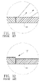
- the pad 90 is a soft material, the joint of the tooth structure 91 is likely to recess or rip apart when they are patched together. Thus, there will be a gap between pads 90 . Moreover, as the pads are not completely attached to the ground, dusts can fall into the gaps. After long-time accumulation, the gaps between the pads 90 and between the ground and the pads 90 will be filled with a lot of dusts. As shown in FIG. 1 , it may be easier to remove the dusts on the surface of the pads 90 when using a vacuum cleaner. But the dusts between the sheet and the ground are difficult to remove. One has to take apart the pads 90 in order to completely clean it.
- Each side of the pad 90 has a tooth structure 91 .
- the corner is usually made to have the same color as the pad 90 .
- the colors alternate at the junction and have inconsistent differences in colors.
- the conventional pads 90 are mostly rectangular. When patching them, one has to consider the problem of joining the tooth structures. Therefore, the variations in shape are limited by the patching method.
- Another conventional patching sheet is attached to the ground with a glue coating on the back.
- the glue is all over the bottom surface and too adhesive to remove in the future. They may be broken or have residues on the ground when being removed.
- glue is more expensive than normal glue. It is then another issue to use an appropriate amount of glue in order to reduce the cost.
- One objective of the invention is to solve the above-mentioned problems by providing a method of manufacturing foam pads and the product thereof.
- the bottom surface of the pad is coated with an adhesive material to be attached to the ground.
- a guiding angle structure is formed around the top surface of the pad by thermal pressing. With such a structure, the pads are tightly attached to the ground and connected to each other. This avoids dusts from falling therein. It also prevents the tooth structure from protruding. Besides, the guiding angle structure of the pad renders a better visual effect in the patched pads.
- Another objective of the invention is to properly design the structure of the bottom surface of the pad, so that the pad can be attached to the ground with less glue. It also achieves the effects of soundproof and preventing mould from growing.
- the disclosed method involves the following steps: heating and pressing around the top surface of each pad and cooling it to form a guiding angle structure; heating the bottom surface of the pad and pressing and cooling to form a pattern; coating an adhesive layer on the relatively protruding surface of the bottom surface for attaching to the ground; and covering the adhesive layer with a release paper.
- the disclosed pad product has: a guiding angle structure around the top surface of the pad, a pattern on its bottom surface, an adhesive layer on the relatively protruding surface of the pattern for attaching to the ground, and a release paper covering the adhesive layer.
- FIG. 1 is a schematic view of the sheet formed by the disclosed pads
- FIG. 2 is a schematic view showing how to make the top surface of the disclosed pad
- FIG. 3 is a schematic view of forming the guiding angle structure with a mold according to the invention.
- FIG. 4 is a schematic view of forming the bottom surface and coating an adhesive layer thereon according to the invention.
- FIG. 5 is a schematic view of the disclosed pad structure
- FIG. 6 is a schematic view of patching the disclosed pads on the ground
- FIG. 7 is a schematic view of cleaning the disclosed pads
- FIG. 8 is a schematic view of looking at the surface of the disclosed pad
- FIG. 9 shows a second embodiment of patching the pads
- FIG. 10 is a schematic view of conventional pads patched together
- FIG. 11 is a schematic view of cleaning the pads of conventional sheet.
- FIG. 12 is a schematic view of looking at the surface of the disclosed pad.
- FIGS. 1 to 9 Please refer to FIGS. 1 to 9 for embodiments of the invention. They are used for the purpose of explanation and should not be used to restrict the scope of the invention.
- This embodiment provides a method of manufacturing a foam sheet. It is then cut into several pads 1 that can be patched into the sheet show in FIG. 1 .
- the surrounding of the top surface 11 of each pad 1 is thermally pressed to form a guiding angle structure.
- the bottom surface 12 of the pad 1 is heated, pressed, and cooled to form a pattern.
- An adhesive layer 13 is coated on the relatively protruding part of the bottom surface 12 to be attached to the ground.
- a release paper 2 the covers the adhesive layer 13 .
- the pad 1 in this embodiment is made of an ethylene vinyl acetate (EVA) foam material. Moreover, the pad 1 is obtained by cutting a big sheet A into a rectangular shape. The adhesive layer 13 on the bottom surface 12 of the pad 1 is cut along with the sheet A.
- the guiding angle structure of the pad 1 is first heated and softened by hot air from a hot wind device 4 , followed by pressing of a roller 5 .
- the roller 5 has a cooling circulation pipeline with cooling water circulating therein (not shown). Therefore, the guiding angle structure is formed by roller pressing and cooling.
- the guiding angle structure can be substituted by some other equivalent process in another embodiment.
- the mold 61 corresponding to the guiding angle structure of the pad 1 has an electric heating pipe 61 and a cooling water circulating pipeline 62 . Therefore, the mold 6 presses against the surrounding of the top surface 11 of the pad 1 after being heated. At the same time, it cools to form the guiding angle structure.
- the pattern on the bottom surface 12 of the pad 1 in this embodiment is formed by using another hot wind device 4 A to blow hot air.
- the bottom surface 12 of the pad is thus softened and pressed by a roller 7 with a pattern, leaving the corresponding pattern on the pad 1 .
- An adhesive material is then coated on the pattern with the roller, forming the adhesive layer 13 .
- Another roller then put the release paper 2 on the adhesive layer 13 .
- the guiding angle structure on the top surface 11 and the pattern on the bottom surface 12 can be simultaneously completed in one transporting process or subsequently in one process or different processes.
- FIGS. 5 and 6 The foam sheet product prepared according to the above-mentioned method of the invention is shown in FIGS. 5 and 6 .
- a guiding angle part 14 is formed around the top surface 11 of the pad 1 .
- the bottom surface 12 has a pattern with alternating protruding part 121 and receding part 122 .
- the surface of the protruding part 121 has an adhesive layer 13 to be attached to the ground.
- a release paper 2 covers the adhesive layer 13 .
- the receding part 122 of the bottom surface 12 and the ground 3 provide a space 15 for air to flow when the pad is attached to the ground 3 .
- the pad 1 is attached to the ground 3 .
- the pads 1 are tightly patched to avoid dusts from falling in between. Even though the guiding angle structure (guiding angle part 14 ) may have dusts accumulated thereon, they do not get between the pads 1 as they are tightly patched. It is relatively easy to clean the pads 1 . For example, as shown in FIG. 7 , the dusts are readily removed by a vacuum cleaner.
- the bottom surface 12 of the disclosed pad 1 has a pattern.
- the adhesive layer 13 is only provided on the surface of the protruding part 121 . Therefore, the amount of adhesive material is less than the prior art, thereby reducing the cost thereof.
- the pattern formed on the bottom surface 12 of the pad 1 renders a better soundproof effect.
- the space 15 formed between the receding part 122 and the ground 3 allows airflow to suppress the growth of mould.
- each pad 1 A has a triangular shape. They are patched into a hexagonal sheet structure. As described in the advantages of the first embodiment, the disclosed pads 1 are fixed to the ground by attaching. Therefore, one can freely design the shape of pads. In comparison with the conventional pad, the invention does not have the restriction due to the tooth structure. It is therefore very flexible and convenient.
Landscapes
- Chemical & Material Sciences (AREA)
- Engineering & Computer Science (AREA)
- Organic Chemistry (AREA)
- Life Sciences & Earth Sciences (AREA)
- Cell Biology (AREA)
- Materials Engineering (AREA)
- Health & Medical Sciences (AREA)
- Chemical Kinetics & Catalysis (AREA)
- Medicinal Chemistry (AREA)
- Polymers & Plastics (AREA)
- Mechanical Engineering (AREA)
- Laminated Bodies (AREA)
Abstract
A method of manufacturing a foam sheet and the product thereof are disclosed. The foam sheet thus formed is cut into several pads. The surrounding of the top surface of each pad is heated, pressed, and cooled to form a guiding angle structure. The bottom surface of the pad is heated, pressed, and cooled to have a pattern. The relatively protruding surface of the bottom surface is coated with an adhesive layer to be attached to the ground. A release paper then covers the adhesive layer. The pads are then patched to form a sheet with the disclosed structure.
Description
- 1. Field of Invention
- The invention relates to a method of manufacturing foam sheets and product thereof. In particular, the invention relates to a method of manufacturing the pad that attaches to the ground and form a sheet and the product thereof.
- 2. Related Art
-
FIG. 10 shows a conventional sheet consisted ofseveral pads 90. As shown in the drawing, eachpad 90 has a rectangular shape. Each side has atooth structure 91 for them to combine with each other. Thepads 90 also have different colors. - However, the
pads 90 in the conventional sheet are usually made by cutting a big sheet. Moreover, thepad 90 is made of a foam material. It is soft and flexible. During the manufacturing process, the thickness of eachpad 90 has an appropriate tolerance (usually about ±0.5 mm). Therefore, they have the following problems. - 1. Since the
pad 90 is a soft material, the joint of thetooth structure 91 is likely to recess or rip apart when they are patched together. Thus, there will be a gap betweenpads 90. Moreover, as the pads are not completely attached to the ground, dusts can fall into the gaps. After long-time accumulation, the gaps between thepads 90 and between the ground and thepads 90 will be filled with a lot of dusts. As shown inFIG. 1 , it may be easier to remove the dusts on the surface of thepads 90 when using a vacuum cleaner. But the dusts between the sheet and the ground are difficult to remove. One has to take apart thepads 90 in order to completely clean it. - 2. Each side of the
pad 90 has atooth structure 91. The corner is usually made to have the same color as thepad 90. However, after thepads 90 of different colors are patched, the colors alternate at the junction and have inconsistent differences in colors. Even ifpads 90 of the same color are used, their surfaces and sides often have slightly different colors. Moreover, they usually have different heights. Consequently, after they are patched, there are still differences in colors, as shown inFIG. 12 . Such a visual difference due to height variations is more prominent. - 3. The
conventional pads 90 are mostly rectangular. When patching them, one has to consider the problem of joining the tooth structures. Therefore, the variations in shape are limited by the patching method. - 4. Another conventional patching sheet is attached to the ground with a glue coating on the back. However, usually the glue is all over the bottom surface and too adhesive to remove in the future. They may be broken or have residues on the ground when being removed. One thus has to use some specific glue with appropriate strength. Such glue is more expensive than normal glue. It is then another issue to use an appropriate amount of glue in order to reduce the cost.
- Therefore, it is an objective to solve the above-mentioned problems in
conventional pads 90 of patching sheet. - One objective of the invention is to solve the above-mentioned problems by providing a method of manufacturing foam pads and the product thereof. The bottom surface of the pad is coated with an adhesive material to be attached to the ground. A guiding angle structure is formed around the top surface of the pad by thermal pressing. With such a structure, the pads are tightly attached to the ground and connected to each other. This avoids dusts from falling therein. It also prevents the tooth structure from protruding. Besides, the guiding angle structure of the pad renders a better visual effect in the patched pads.
- Another objective of the invention is to properly design the structure of the bottom surface of the pad, so that the pad can be attached to the ground with less glue. It also achieves the effects of soundproof and preventing mould from growing.
- To achieve the above-mentioned objectives, the disclosed method involves the following steps: heating and pressing around the top surface of each pad and cooling it to form a guiding angle structure; heating the bottom surface of the pad and pressing and cooling to form a pattern; coating an adhesive layer on the relatively protruding surface of the bottom surface for attaching to the ground; and covering the adhesive layer with a release paper.
- The disclosed pad product has: a guiding angle structure around the top surface of the pad, a pattern on its bottom surface, an adhesive layer on the relatively protruding surface of the pattern for attaching to the ground, and a release paper covering the adhesive layer.
- The invention will become more fully understood from the detailed description given herein below illustration only, and thus is not limitative of the present invention, and wherein:
-
FIG. 1 is a schematic view of the sheet formed by the disclosed pads; -
FIG. 2 is a schematic view showing how to make the top surface of the disclosed pad; -
FIG. 3 is a schematic view of forming the guiding angle structure with a mold according to the invention; -
FIG. 4 is a schematic view of forming the bottom surface and coating an adhesive layer thereon according to the invention; -
FIG. 5 is a schematic view of the disclosed pad structure; -
FIG. 6 is a schematic view of patching the disclosed pads on the ground; -
FIG. 7 is a schematic view of cleaning the disclosed pads; -
FIG. 8 is a schematic view of looking at the surface of the disclosed pad; -
FIG. 9 shows a second embodiment of patching the pads; -
FIG. 10 is a schematic view of conventional pads patched together; -
FIG. 11 is a schematic view of cleaning the pads of conventional sheet; and -
FIG. 12 is a schematic view of looking at the surface of the disclosed pad. - The present invention will be apparent from the following detailed description, which proceeds with reference to the accompanying drawings, wherein the same references relate to the same elements.
- Please refer to
FIGS. 1 to 9 for embodiments of the invention. They are used for the purpose of explanation and should not be used to restrict the scope of the invention. - This embodiment provides a method of manufacturing a foam sheet. It is then cut into
several pads 1 that can be patched into the sheet show inFIG. 1 . - According to the disclosed method, the surrounding of the
top surface 11 of eachpad 1 is thermally pressed to form a guiding angle structure. Thebottom surface 12 of thepad 1 is heated, pressed, and cooled to form a pattern. Anadhesive layer 13 is coated on the relatively protruding part of thebottom surface 12 to be attached to the ground. Arelease paper 2 the covers theadhesive layer 13. - As shown in
FIG. 2 , thepad 1 in this embodiment is made of an ethylene vinyl acetate (EVA) foam material. Moreover, thepad 1 is obtained by cutting a big sheet A into a rectangular shape. Theadhesive layer 13 on thebottom surface 12 of thepad 1 is cut along with the sheet A. In this embodiment, the guiding angle structure of thepad 1 is first heated and softened by hot air from a hot wind device 4, followed by pressing of a roller 5. The roller 5 has a cooling circulation pipeline with cooling water circulating therein (not shown). Therefore, the guiding angle structure is formed by roller pressing and cooling. - Besides, the guiding angle structure can be substituted by some other equivalent process in another embodiment. As shown in
FIG. 3 , themold 61 corresponding to the guiding angle structure of thepad 1 has anelectric heating pipe 61 and a coolingwater circulating pipeline 62. Therefore, the mold 6 presses against the surrounding of thetop surface 11 of thepad 1 after being heated. At the same time, it cools to form the guiding angle structure. - As shown in
FIG. 4 , the pattern on thebottom surface 12 of thepad 1 in this embodiment is formed by using anotherhot wind device 4A to blow hot air. Thebottom surface 12 of the pad is thus softened and pressed by a roller 7 with a pattern, leaving the corresponding pattern on thepad 1. An adhesive material is then coated on the pattern with the roller, forming theadhesive layer 13. Another roller then put therelease paper 2 on theadhesive layer 13. - In the above-mentioned
pad 1, the guiding angle structure on thetop surface 11 and the pattern on thebottom surface 12 can be simultaneously completed in one transporting process or subsequently in one process or different processes. - The foam sheet product prepared according to the above-mentioned method of the invention is shown in
FIGS. 5 and 6 . As shown in the drawing, a guidingangle part 14 is formed around thetop surface 11 of thepad 1. Thebottom surface 12 has a pattern with alternating protrudingpart 121 and recedingpart 122. The surface of theprotruding part 121 has anadhesive layer 13 to be attached to the ground. Arelease paper 2 covers theadhesive layer 13. The recedingpart 122 of thebottom surface 12 and theground 3 provide aspace 15 for air to flow when the pad is attached to theground 3. - From the above description, it is not difficult to discover the following primary advantages of the invention:
- 1. The
pad 1 is attached to theground 3. Thepads 1 are tightly patched to avoid dusts from falling in between. Even though the guiding angle structure (guiding angle part 14) may have dusts accumulated thereon, they do not get between thepads 1 as they are tightly patched. It is relatively easy to clean thepads 1. For example, as shown inFIG. 7 , the dusts are readily removed by a vacuum cleaner. - 2. Conventional pads are mostly rectangular. Therefore, one has to consider the junction problem of the tooth structure when patching them together. The shape of the pads is thus very limited. According to the invention, the
pads 1 are fixed by attaching. Therefore, there is no limitation in the shape. Besides, the disclosedpad 1 is visually more beautiful after patching because of the guiding angle structure (guiding angle part 14). - 3. After the formation of a usual pad, its surface is printed with a color. As shown in
FIG. 8 , thecolor layer 16 printed on the surface of the disclosed pad extends along the edge of the guiding angle structure (guiding angle part 14). Consequently, after the pads are patched together, the printed color is continuous even if there is a height difference between pads. This is because of the curvature of the guiding angle structure (guiding angle part 14). The invention is thus visually consistent in color, unlike conventional pads. - 4. The
bottom surface 12 of the disclosedpad 1 has a pattern. Theadhesive layer 13 is only provided on the surface of theprotruding part 121. Therefore, the amount of adhesive material is less than the prior art, thereby reducing the cost thereof. Moreover, the pattern formed on thebottom surface 12 of thepad 1 renders a better soundproof effect. Besides, thespace 15 formed between the recedingpart 122 and theground 3 allows airflow to suppress the growth of mould. - Of course, the invention has many other embodiments that differ from the one disclosed herein in detail. Please refer to
FIG. 9 for a second embodiment. Each pad 1A has a triangular shape. They are patched into a hexagonal sheet structure. As described in the advantages of the first embodiment, the disclosedpads 1 are fixed to the ground by attaching. Therefore, one can freely design the shape of pads. In comparison with the conventional pad, the invention does not have the restriction due to the tooth structure. It is therefore very flexible and convenient. - Although the invention has been described with reference to specific embodiments, this description is not meant to be construed in a limiting sense. Various modifications of the disclosed embodiments, as well as alternative embodiments, will be apparent to people skilled in the art. Therefore, it is contemplated that the appended claims will cover all modifications that fall within the true scope of the invention.
Claims (7)
1. A method of manufacturing a foam sheet to be cut into a plurality of pads, comprising the steps of:
forming a guiding angle structure by heating, pressing, and cooling around the top surface of each pad or by heating and pressing around the top surface of each pad and then cooling it;
heating the bottom surface of the pad and pressing and cooling to form a pattern;
coating an adhesive layer on the relatively protruding surface of the bottom surface for attaching to the ground; and
covering the adhesive layer with a release paper.
2. The method of manufacturing a foam sheet according to claim 1 , wherein the guiding angle structure on the top surface and the pattern on the bottom surface of the pad are first heated and softened, followed by cooling formation.
3. The method of manufacturing a foam sheet according to claim 1 , wherein the guiding angle structure on the top surface and the pattern on the bottom surface of the pad are formed by heating, pressing, and cooling with a respective mold of a corresponding structure.
4. The method of manufacturing a foam sheet according to claim 1 , wherein the surrounding of the top surface of the pad has a guiding angle structure and the bottom surface has a pattern with alternating protruding part and receding part, the surface of the protruding part is coated with an adhesive layer to be attached to the ground, a release paper covers the adhesive layer, and a space for airflow is formed between the receding part and the ground.
5. The method of manufacturing a foam sheet according to claim 4 , wherein the guiding angle structure on the top surface and the pattern on the bottom surface of the pad are first heated and softened, followed by cooling formation.
6. The method of manufacturing a foam sheet according to claim 4 , wherein the guiding angle structure on the top surface and the pattern on the bottom surface of the pad are formed by heating, pressing, and cooling with a respective mold of a corresponding structure.
7. The form sheet product of claim 4 , wherein the guiding angle of the pad is a guiding arc angle.
Priority Applications (1)
| Application Number | Priority Date | Filing Date | Title |
|---|---|---|---|
| US12/501,458 US20110008564A1 (en) | 2009-07-12 | 2009-07-12 | Method of manufacturing foam sheets and product thereof |
Applications Claiming Priority (1)
| Application Number | Priority Date | Filing Date | Title |
|---|---|---|---|
| US12/501,458 US20110008564A1 (en) | 2009-07-12 | 2009-07-12 | Method of manufacturing foam sheets and product thereof |
Publications (1)
| Publication Number | Publication Date |
|---|---|
| US20110008564A1 true US20110008564A1 (en) | 2011-01-13 |
Family
ID=43427689
Family Applications (1)
| Application Number | Title | Priority Date | Filing Date |
|---|---|---|---|
| US12/501,458 Abandoned US20110008564A1 (en) | 2009-07-12 | 2009-07-12 | Method of manufacturing foam sheets and product thereof |
Country Status (1)
| Country | Link |
|---|---|
| US (1) | US20110008564A1 (en) |
-
2009
- 2009-07-12 US US12/501,458 patent/US20110008564A1/en not_active Abandoned
Similar Documents
| Publication | Publication Date | Title |
|---|---|---|
| JP6236115B2 (en) | Flexible glass roll and winding method thereof | |
| TWI457233B (en) | Groove type vacuum heat insulation material | |
| WO2008120499A1 (en) | Honeycomb segment | |
| CN106193515A (en) | Non-polyvinyl chloride floor tile | |
| US20110008564A1 (en) | Method of manufacturing foam sheets and product thereof | |
| CN203771313U (en) | Backlight module and display device | |
| US10132081B2 (en) | High elongation ridge ventilation sheet for sloping roof and fabricating method therefor | |
| FR2845714A1 (en) | ASSEMBLY MODULE FOR FLOORING OR WALL COVERINGS | |
| US20100086748A1 (en) | Foam Sheets And Method Of Making The Same | |
| KR20140057067A (en) | Hydrogel mask sheet with uneven surface and the manufacturing method thereof | |
| CN208822244U (en) | A kind of anti-deformation stair step pad wound | |
| CN207154958U (en) | A kind of FPC backing plates effectively to increase the service life | |
| JP2020520872A5 (en) | ||
| TW201413995A (en) | Solar cell packaging material sheet, and solar cell module | |
| US6752615B2 (en) | Forming mold for a lens sheet | |
| CA2898628C (en) | Composite adhesive tape | |
| CN214739367U (en) | Waterproof material with insulating material layer | |
| TWI586457B (en) | Containing device of ingot casting furnace for containing materials of ingot and method of casting ingot | |
| JP2007227559A (en) | Coverlay and flexible printed wiring board manufacturing method | |
| KR101157877B1 (en) | Jig for adhering hotfix to expansion band | |
| CN114150829A (en) | Anti-deformation heat-preservation honeycomb core aluminum buckle plate and production method thereof | |
| KR20100062588A (en) | Method for manufacturing eva mat with printed sheet | |
| JP5332976B2 (en) | Tile connection sheet and tile unit | |
| KR101722111B1 (en) | Aluminum sheet for heat insulating material and manufacturing method thereof | |
| TWM481197U (en) | Caterpillar-type corrugated board |
Legal Events
| Date | Code | Title | Description |
|---|---|---|---|
| AS | Assignment |
Owner name: CHIANG, MIN-CHEN, TAIWAN Free format text: ASSIGNMENT OF ASSIGNORS INTEREST;ASSIGNOR:WANG, HUI-LI;REEL/FRAME:022943/0298 Effective date: 20090610 |
|
| STCB | Information on status: application discontinuation |
Free format text: ABANDONED -- FAILURE TO RESPOND TO AN OFFICE ACTION |