US20100166370A1 - Bi-Directional Tap Assemblies for Two-Way Fiber Topologies - Google Patents
Bi-Directional Tap Assemblies for Two-Way Fiber Topologies Download PDFInfo
- Publication number
- US20100166370A1 US20100166370A1 US12/267,179 US26717908A US2010166370A1 US 20100166370 A1 US20100166370 A1 US 20100166370A1 US 26717908 A US26717908 A US 26717908A US 2010166370 A1 US2010166370 A1 US 2010166370A1
- Authority
- US
- United States
- Prior art keywords
- fiber
- cable
- tether
- fibers
- bend
- Prior art date
- Legal status (The legal status is an assumption and is not a legal conclusion. Google has not performed a legal analysis and makes no representation as to the accuracy of the status listed.)
- Granted
Links
- 239000000835 fiber Substances 0.000 title claims abstract description 303
- 230000000712 assembly Effects 0.000 title abstract description 8
- 238000000429 assembly Methods 0.000 title abstract description 8
- 239000013307 optical fiber Substances 0.000 claims abstract description 85
- 230000003287 optical effect Effects 0.000 claims abstract description 24
- 238000000034 method Methods 0.000 claims description 24
- 230000001681 protective effect Effects 0.000 claims description 20
- 230000008878 coupling Effects 0.000 claims description 4
- 238000010168 coupling process Methods 0.000 claims description 4
- 238000005859 coupling reaction Methods 0.000 claims description 4
- 238000011144 upstream manufacturing Methods 0.000 abstract description 26
- 239000002086 nanomaterial Substances 0.000 description 32
- 238000009826 distribution Methods 0.000 description 21
- VYPSYNLAJGMNEJ-UHFFFAOYSA-N Silicium dioxide Chemical compound O=[Si]=O VYPSYNLAJGMNEJ-UHFFFAOYSA-N 0.000 description 18
- 238000005253 cladding Methods 0.000 description 13
- 239000000463 material Substances 0.000 description 12
- 238000010586 diagram Methods 0.000 description 10
- 239000011521 glass Substances 0.000 description 10
- 239000000377 silicon dioxide Substances 0.000 description 9
- 230000000737 periodic effect Effects 0.000 description 7
- 238000004891 communication Methods 0.000 description 6
- 239000007789 gas Substances 0.000 description 6
- YBMRDBCBODYGJE-UHFFFAOYSA-N germanium dioxide Chemical compound O=[Ge]=O YBMRDBCBODYGJE-UHFFFAOYSA-N 0.000 description 6
- 230000005540 biological transmission Effects 0.000 description 4
- 238000009434 installation Methods 0.000 description 4
- 238000000465 moulding Methods 0.000 description 4
- PXGOKWXKJXAPGV-UHFFFAOYSA-N Fluorine Chemical compound FF PXGOKWXKJXAPGV-UHFFFAOYSA-N 0.000 description 3
- 239000000654 additive Substances 0.000 description 3
- 230000000994 depressogenic effect Effects 0.000 description 3
- 239000002019 doping agent Substances 0.000 description 3
- 229910052731 fluorine Inorganic materials 0.000 description 3
- 239000011737 fluorine Substances 0.000 description 3
- 235000012239 silicon dioxide Nutrition 0.000 description 3
- 239000011800 void material Substances 0.000 description 3
- XKRFYHLGVUSROY-UHFFFAOYSA-N Argon Chemical compound [Ar] XKRFYHLGVUSROY-UHFFFAOYSA-N 0.000 description 2
- IJGRMHOSHXDMSA-UHFFFAOYSA-N Atomic nitrogen Chemical compound N#N IJGRMHOSHXDMSA-UHFFFAOYSA-N 0.000 description 2
- 238000004512 die casting Methods 0.000 description 2
- 238000005516 engineering process Methods 0.000 description 2
- 239000012530 fluid Substances 0.000 description 2
- 239000011159 matrix material Substances 0.000 description 2
- 238000012986 modification Methods 0.000 description 2
- 230000004048 modification Effects 0.000 description 2
- 239000012778 molding material Substances 0.000 description 2
- 238000007789 sealing Methods 0.000 description 2
- 229920001169 thermoplastic Polymers 0.000 description 2
- 239000004416 thermosoftening plastic Substances 0.000 description 2
- RNFJDJUURJAICM-UHFFFAOYSA-N 2,2,4,4,6,6-hexaphenoxy-1,3,5-triaza-2$l^{5},4$l^{5},6$l^{5}-triphosphacyclohexa-1,3,5-triene Chemical compound N=1P(OC=2C=CC=CC=2)(OC=2C=CC=CC=2)=NP(OC=2C=CC=CC=2)(OC=2C=CC=CC=2)=NP=1(OC=1C=CC=CC=1)OC1=CC=CC=C1 RNFJDJUURJAICM-UHFFFAOYSA-N 0.000 description 1
- BQCADISMDOOEFD-UHFFFAOYSA-N Silver Chemical compound [Ag] BQCADISMDOOEFD-UHFFFAOYSA-N 0.000 description 1
- 230000000996 additive effect Effects 0.000 description 1
- 238000013459 approach Methods 0.000 description 1
- 229910052786 argon Inorganic materials 0.000 description 1
- QVGXLLKOCUKJST-UHFFFAOYSA-N atomic oxygen Chemical compound [O] QVGXLLKOCUKJST-UHFFFAOYSA-N 0.000 description 1
- 230000015572 biosynthetic process Effects 0.000 description 1
- 239000003054 catalyst Substances 0.000 description 1
- 238000004140 cleaning Methods 0.000 description 1
- 229910052681 coesite Inorganic materials 0.000 description 1
- 239000003086 colorant Substances 0.000 description 1
- 238000007596 consolidation process Methods 0.000 description 1
- 238000005336 cracking Methods 0.000 description 1
- 229910052906 cristobalite Inorganic materials 0.000 description 1
- 238000005520 cutting process Methods 0.000 description 1
- 230000003247 decreasing effect Effects 0.000 description 1
- 235000004879 dioscorea Nutrition 0.000 description 1
- 239000000975 dye Substances 0.000 description 1
- 230000000694 effects Effects 0.000 description 1
- 229920001971 elastomer Polymers 0.000 description 1
- 239000000806 elastomer Substances 0.000 description 1
- 239000003063 flame retardant Substances 0.000 description 1
- 230000009969 flowable effect Effects 0.000 description 1
- 239000006260 foam Substances 0.000 description 1
- 239000005350 fused silica glass Substances 0.000 description 1
- 238000001746 injection moulding Methods 0.000 description 1
- 238000004519 manufacturing process Methods 0.000 description 1
- 238000012806 monitoring device Methods 0.000 description 1
- 238000012544 monitoring process Methods 0.000 description 1
- 229910052757 nitrogen Inorganic materials 0.000 description 1
- 239000001301 oxygen Substances 0.000 description 1
- 229910052760 oxygen Inorganic materials 0.000 description 1
- 230000000149 penetrating effect Effects 0.000 description 1
- 239000004038 photonic crystal Substances 0.000 description 1
- 239000004033 plastic Substances 0.000 description 1
- 229920003023 plastic Polymers 0.000 description 1
- 239000004014 plasticizer Substances 0.000 description 1
- 229920001296 polysiloxane Polymers 0.000 description 1
- 229920002635 polyurethane Polymers 0.000 description 1
- 239000004814 polyurethane Substances 0.000 description 1
- 239000011241 protective layer Substances 0.000 description 1
- 238000007788 roughening Methods 0.000 description 1
- 238000004626 scanning electron microscopy Methods 0.000 description 1
- 229910052709 silver Inorganic materials 0.000 description 1
- 239000004332 silver Substances 0.000 description 1
- 230000003595 spectral effect Effects 0.000 description 1
- 229910052682 stishovite Inorganic materials 0.000 description 1
- 239000000126 substance Substances 0.000 description 1
- 229920001187 thermosetting polymer Polymers 0.000 description 1
- 229910052905 tridymite Inorganic materials 0.000 description 1
Images


Classifications
-
- G—PHYSICS
- G02—OPTICS
- G02B—OPTICAL ELEMENTS, SYSTEMS OR APPARATUS
- G02B6/00—Light guides; Structural details of arrangements comprising light guides and other optical elements, e.g. couplings
- G02B6/44—Mechanical structures for providing tensile strength and external protection for fibres, e.g. optical transmission cables
- G02B6/4439—Auxiliary devices
- G02B6/4471—Terminating devices ; Cable clamps
- G02B6/4472—Manifolds
- G02B6/4475—Manifolds with provision for lateral branching
-
- G—PHYSICS
- G02—OPTICS
- G02B—OPTICAL ELEMENTS, SYSTEMS OR APPARATUS
- G02B6/00—Light guides; Structural details of arrangements comprising light guides and other optical elements, e.g. couplings
- G02B6/02—Optical fibres with cladding with or without a coating
- G02B6/02295—Microstructured optical fibre
- G02B6/02314—Plurality of longitudinal structures extending along optical fibre axis, e.g. holes
- G02B6/02342—Plurality of longitudinal structures extending along optical fibre axis, e.g. holes characterised by cladding features, i.e. light confining region
Definitions
- the present invention relates generally to fiber-optic cables used in telecommunication systems, and in particular relates to bi-directional tap assemblies arranged at mid-span access locations of two-way fiber topologies.
- Optical fiber is used for a variety of broadband telecommunication applications that involve voice, video and/or data transmissions.
- Such fiber-based telecommunication systems utilize fiber-optic cables (e.g., “distribution cables”) that include a number of mid-span access locations at which one or more optical fibers are terminated and interconnected with a branch cable or a drop cable.
- the mid-span access locations provide an interconnection point, also referred to as “access point” or “tap point” (or just “tap” for short) from the distribution cable.
- the interconnection point can include a tap assembly that connects optical fibers in the distribution cable to another location, such as another network distribution cable or termination point, or directly to an end user, commonly referred to as a subscriber, thereby extending an “all optical” communications network closer to the subscriber.
- fiber optic networks are being developed that deliver “fiber-to-the-curb” (FTTC), “fiber-to-the-business” (FTTB), “fiber-to-the-home” (FTTH), or “fiber-to-the-premises” (FTTP), referred to generically as “FTTx.”
- Tap assemblies are common for one-way fiber topologies wherein optical signals travel in a single direction. Such taps are typically formed by accessing an optical fiber in a fiber optical cable and cutting the fiber to form two fiber sections. One of the fiber sections is terminated (e.g., spliced to a connectorized section of optical fiber) to form the tap, while the other section of the fiber becomes “dark fiber” because it is not utilized in the one-way topology.
- This approach cannot be used for two-way fiber topologies because the fibers carry signals in two directions. This means that one section of the fiber cannot be disregarded in forming the tap.
- a bi-directional tap assembly includes at least one short length of cable, referred to herein as a “tether.”
- the tether is attached (e.g., spliced or otherwise optically connected) to an optical fiber of a fiber optical cable at a mid-span location.
- the mid-span location is also referred to as a “tap point.”
- the bi-directionality of the tap assembly means that at least one “upstream” and at least one “downstream” optical fiber is accessed at the tap point, wherein “upstream” and “downstream” are relative terms used to indicate direction in which information travels over the fiber-optic cable from one or more reference locations, such as a central office or other types of communications management centers or telecommunication devices.
- a single optical fiber carries optical signals in both directions.
- Bi-directionality is associated with a ring network topology where a fiber-optic cable begins and ends at the same location, e.g., a central office. Bi-directionality also is associated with a non-ring topology where ends of a distribution cable terminate at respective locations that transmit and receive information over the distribution cable.
- at least one optical fiber in the system is configured to carry optical signals in two directions.
- the tether of the tap assembly permits at least one connector to be positioned at a desired location in a fiber optic communications network.
- the tether is manufactured in the factory and spliced or otherwise optically connected in the field to a previously installed fiber optic distribution cable.
- the tap assembly (including a tether and at least one connector) is manufactured in the factory (i.e., factory-prepared) for a pre-engineered fiber optic communications network and wound onto a cable reel for deployment in the field.
- a tether can be of any length, in practice it typically provides a relatively short length of cable (as compared to the distribution cable) to allow a distribution or termination point to be positioned at a desired location.
- the tether has a length up to about 100 feet, more especially about 25 feet, and preferably a length of about 12 to about 15 feet.
- the tether eliminates the need for absolute accuracy in the engineering of the fiber optic network, the manufacture of the distribution tap assembly and the deployment of the distribution tap assembly.
- the tap assembly includes two tethers: an upstream tether and a downstream tether.
- tether optical fibers can be connectorized with a tether connector, such as with one of the following connector types: SC, LC, DC, FC, ST, SC/DC, MT, MT-RJ, MTP, MPO.
- SC single or multi-fiber connectors now known or hereafter developed can also be used.
- a first aspect of the invention is a bi-directional tap assembly that includes a fiber-optic cable having at least one cable optical fiber.
- the cable optical fiber is adapted to carry bi-directional optical signals and is preterminated at a mid-span location to form a first cable fiber section having a first cable fiber end and a second cable fiber section having a second cable fiber end.
- the bi-directional tap assembly can include at least one tether formed at both cable fiber sections, from one cable fiber section and one tether fiber, or from tether fibers optically connected to the respective cable fiber sections.
- a second aspect of the invention is a method of forming a bi-directional tap in a fiber-optic cable that includes at least one cable optical fiber.
- the method includes preterminating, at a mid-span location, the at least one cable optical fiber to form corresponding at least one first and at least one second cable fiber sections having respective first and second cable fiber ends.
- the method also includes optically coupling the at least one first and the at least one second cable fiber sections at their respective first and second cable fiber ends to respective at least one first and at least one second tether fibers.
- An example embodiment of the method includes performing the above acts of the method prior to deploying the cable.
- a third aspect of the invention is the combination of accessed fibers.
- a multifiber cable whether a ribbon fiber cable or a loose tube cable
- one particular tap point might access fibers ribers 1 - 4 from the upstream direction and fibers 5 - 8 from the downstream direction, leaving fibers 9 - 12 as express fibers, for example. Downstream, therefore, fibers 1 - 4 are “dark”, but can be accessed in a subsequent tap point from the downstream direction.
- fibers 5 - 8 can be accessed upstream of the original tap point, creating a tether location and utilizing, from both directions, the full use of fibers 1 - 8 , with direct or indirect communication with the central office by virtue of the “bi-directionality” of the technology. While all combinations of accessing fibers are exhaustive and not specifically covered by this invention, they are within the scope of the technology covered by this invention.
- FIG. 1 is a schematic side view of a section of an example embodiment of a bend-insensitive optical fiber in the form of a nanostructure optical fiber;
- FIG. 2A is a schematic diagram of an example cross-section of the optical fiber of FIG. 1 as viewed along the direction 2 A- 2 A;
- FIG. 2B is a schematic diagram illustrating the bend angle 0 B and the bend diameter DB of a bend formed in the bend-insensitive optical fiber of FIG. 1 ;
- FIG. 3A is a schematic diagram of a bi-directional telecommunication system having a ring-topology and that includes a fiber-optic cable with two bi-directional tap assemblies arranged at respective mid-span access locations;
- FIG. 3B is a close-up view of a connectorized embodiment of one of the tethers of FIG. 3A ;
- FIG. 3C is a schematic diagram of a linear bi-directional telecommunication system that includes a fiber-optic cable with a single bi-directional tap assembly arranged at a mid-span access location;
- FIG. 4A is a schematic close-up side view of a stripped section of an example fiber-optic cable showing a twisted array of buffer tubes carried by the cable;
- FIG. 4C is similar to FIG. 4B , but showing sections of two different buffer tubes
- FIG. 5A is similar to FIG. 4C , but illustrating two tether fibers spliced to respective cable fiber ends;
- FIG. 5B is similar to FIG. 5A , and illustrates the tether fibers contained in respective tether covers to form respective tethers;
- FIG. 5C is similar to FIG. 5B , and illustrates an example embodiment that includes a single tether cover that extends along the fiber-optic cable and that is used to contain the tether fibers and form two tethers;
- FIG. 6D is similar to FIG. 6C and illustrates an example embodiment wherein the cable fiber sections are connected directly to the adapter;
- FIG. 7A is a schematic side view of another example embodiment of a bi-directional tap that includes a single tether that is translatable along the length of the fiber-optic cable;
- FIG. 7B is similar to FIG. 7A , and shows a fiber cut location where the select cable fibers can be accessed and cut using a fiber access tool;
- Example embodiments make use of “bend-improved” or “bend performance” optical fibers that may have varying degrees of insensitivity to bends.
- One type of fiber useful in the present embodiments is “bend-insensitive” fiber, such as fiber in the form of so-called “nanostructure” or “holey” optical fibers.
- Nanostructure fibers have one or more regions with periodically or a periodically arranged small holes or voids, which make the fiber extremely bend insensitive.
- Bend-insensitive fibers as used in the present invention include, for example, nanostructure fibers of the type available from Corning, Inc., of Corning, N.Y., including, but not limited to, single-mode, multi-mode, bend performance fiber, bend-optimized fiber and bend-insensitive optical fiber. Nanostructure fibers are advantageous in that they allow for the tap assemblies of the present invention to have fibers with relatively small-radius bends while optical attenuation in the fibers remains extremely low.
- FIG. 1 is a schematic side view of a section of an example embodiment of a bend-insensitive fiber in the form of a nanostructure optical fiber (“nanostructure fiber”) 12 having a central axis A F .
- FIG. 2A is a schematic cross-section of nanostructure fiber 12 as viewed along the direction 2 A- 2 A in FIG. 1 .
- Nanostructure fiber 12 can be, for example, any one of the various types of nanostructure optical fibers, such as so-called “holey” fibers.
- a “bend-insensitive fiber” includes nanostructure fibers that make use of periodic or non-periodic nanostructures or holes.
- nanostructure optical fiber 12 includes a core region (“core”) 20 , a nanostructure region 30 surrounding the core, and an outer cladding region 40 (“cladding”) surrounding the nanostructure region.
- core core
- cladding outer cladding region 40
- Other ring-type configurations for nanostructure optical fiber 12 are also known.
- a protective cover or sheath optionally covers outer cladding 40 .
- nanostructure region 30 comprises a glass matrix (“glass”) 31 having formed therein non-periodically disposed holes (also called “voids” or “airlines”) 32 , such as the example voids shown in detail in the magnified inset of FIG. 2A .
- voids 32 may be periodically disposed, such as in a photonic crystal optical fiber, wherein the voids typically have diameters between about 1 ⁇ 10 ⁇ 6 m and 1 ⁇ 10 ⁇ 5 m.
- Voids 32 may also be “non-periodic airlines.”
- glass 31 is fluorine-doped while in another example embodiment the glass is undoped pure silica.
- non-periodically disposed holes/voids 32 are employed in nanostructure region 30 , it is desirable in one example embodiment that they be formed such that greater than 95% of and that all of the holes exhibit a mean hole size in the cladding for the optical fiber which is less than 1550 nm, especially less than 775 nm, and preferably less than about 390 nm.
- the maximum diameter of the holes in the fiber is less than 7000 nm, especially less than 2000 nm, and preferably less than 1550 nm, and most preferably less than 775 nm.
- an optical fiber exhibits fewer than 200 holes in the optical fiber, the holes having a maximum diameter less than 1550 nm and a mean diameter less than 775 nm, although useful and bend resistant optical fibers can be achieved using larger and greater numbers of holes.
- the hole number, mean diameter, max diameter, and total void area percent of holes can all be calculated with the help of a scanning electron microscope at a magnification of about 800 ⁇ to about 4000 ⁇ and image analysis software, such as ImagePro, which is available from Media Cybernetics, Inc. of Silver Spring, Md., USA.
- holes/voids 32 can contain one or more gases, such as argon, nitrogen, or oxygen, or the holes can contain a vacuum with substantially no gas; regardless of the presence or absence of any gas, the refractive index of the hole-containing region is lowered due to the presence of the holes.
- the holes can be periodically or non-periodically disposed.
- the plurality of holes comprises a plurality of non-periodically disposed holes and a plurality of periodically disposed holes.
- the depressed index can also be provided by downdoping the glass in the hole-containing region (such as with fluorine) or updoping one or both of the surrounding regions.
- Nanostructure region 30 can be made by methods that utilize preform consolidation conditions, which are effective at trapping significant amounts of gases in the consolidated glass blank, thereby causing the formation of voids in the consolidated glass optical fiber preform. Rather than taking steps to remove these voids, the resultant preform is used to form an optical fiber with voids, or holes, therein.
- the diameter of a hole is the longest line segment whose end points are disposed on the silica internal surface defining the hole when the optical fiber is viewed in a perpendicular cross-section transverse to the optical fiber central axis A F .
- the nanostructure region 30 comprised approximately 2.5 percent regional area percent holes (100% N 2 by volume) in that area with an average diameter of 0.28 ⁇ m and the smallest diameter holes at 0.17 ⁇ m and a maximum diameter of 0.48 ⁇ m, resulting in a total of about 130 holes in the fiber cross-section.
- the total fiber void area percent (area of the holes divided by the total area of the optical fiber cross-section ⁇ 100) was about 0.05 percent.
- Optical properties for this fiber were 0.36 and 0.20 dB/Km at 1310 and 1550 nm, respectively, and a 22-meter fiber cable cut-off of about 1250 nm, thereby making the fiber single mode at wavelengths above 1250 nm.
- the nanostructure optical fibers used herein may or may not include germania or fluorine to adjust the refractive index of the core and/or cladding of the optical fiber, but these dopants can also be avoided in the intermediate annular region and instead, the holes (in combination with any gas or gases that may be disposed within the holes) can be used to adjust the manner in which light is guided down the fiber core.
- the nanostructure region 30 may consist of undoped (pure) silica, thereby completely avoiding the use of any dopants in the hole-containing region, to achieve a decreased refractive index, or the nanostructure region may comprise doped silica, e.g. fluorine-doped silica having a plurality of holes.
- the core includes doped silica to provide a positive refractive index relative to pure silica, e.g. germania doped silica.
- the core region is preferably hole-free.
- Such fiber can be made to exhibit a fiber cut-off of less than 1400 nm, more preferably less than 1310 nm, a 20-mm macrobend induced loss at 1550 nm of less than 1 dB/turn, preferably less than 0.5 dB/turn, even more preferably less than 0.1 dB/turn, still more preferably less than 0.05 dB/turn, yet more preferably less than 0.03 dB/turn, and even still more preferably less than 0.02 dB/turn, a 12-mm macrobend induced loss at 1550 nm of less than 5 dB/turn, preferably less than 1 dB/turn, more preferably less than 0.5 dB/turn, even more preferably less than 0.2 dB/turn, still more preferably less than 0.01 dB/turn, still even more preferably less than 0.05 dB/turn, and an 8-mm macrobend induced loss at 1550 nm of less than 5 dB/turn, preferably less than
- the multimode nanostructure optical fiber exhibits very low bend-induced attenuation, in particular very low macrobending.
- high bandwidth is provided by low maximum relative refractive index in the core, and low bend losses are also provided.
- the core radius is large (e.g. greater than 20 ⁇ m), the core refractive index is low (e.g. less than 1.0%), and the bend losses are low.
- the multimode nanostructure optical fiber exhibits a spectral attenuation of less than 3 dB/km at 850 nm.
- the numerical aperture (NA) of the nanostructure optical fiber used herein is preferably greater than the NA of the optical source directing signals into the fiber; for example, the NA of the optical fiber is preferably greater than the NA of a VCSEL light source.
- the bandwidth of the multimode optical fiber varies inversely with the square of ⁇ 1 MAX .
- a multimode optical fiber with ⁇ 1 MAX of 0.5% can yield a bandwidth 16 times greater than an otherwise identical multimode optical fiber except having a core with ⁇ 1 MAX of 2.0%.
- the core extends radially outwardly from the centerline to a radius R 1 , wherein 12.5 ⁇ m ⁇ R 1 ⁇ 40 ⁇ m.
- Such multimode fibers preferably exhibit a 1-turn 10 mm diameter mandrel attenuation increase of no more than 1.0 dB, preferably no more than 0.5 dB, more preferably no more than 0.25 dB, even more preferably no more than 0.1 dB, and still more preferably no more than 0.05 dB, at all wavelengths between 800 and 1400 nm.
- Optical signals carried by cable fibers can travel from central station 110 in both directions as uplink and downlink signals SA and SB, as shown. Note that uplink signal SA travels toward uplink T/R unit 112 A and downlink signal SB travels toward downlink T/R unit 112 B.
- 3B is a close-up view of a connectorized upstream tether 134 that has a proximal end 136 , a distal end 137 , and a connector 138 at tether distal end 137 .
- the tether fibers are formed from sections of cable fibers 124 carried by fiber-optic cable 120 .
- bi-directional telecommunication system 100 further includes at least one external device 140 optically coupled to at least one of tethers 134 A and 134 B.
- External device 140 may be, for example, a traffic-monitoring device that produces traffic monitoring data in the form of optical data signals provided to central station 110 via optical fiber tethers 134 A and 134 B and fiber-optic cable 120 .
- External device 140 may also be adapted to receive command signals from central station 110 , as well as signals from another external device 140 .
- External device 140 may also be, for example, a single-port or multi-port connection terminal.
- FIG. 3C is a schematic diagram of an example embodiment of another bi-directional telecommunication system 100 that utilizes a linear topology.
- System 100 of FIG. 3C includes two end-stations 110 A and 110 B that respectively include upstream and downstream T/R units 112 A and 112 B.
- the T/R units 112 A and 112 B are optically coupled by fiber-optic cable 120 .
- a single bi-directional tap assembly 130 at one mid-span location is shown by way of illustration.
- Upstream and downstream T/R units 112 A and 112 B exchange uplink and downlink optical signals SA and SB, which can also be tapped and re-directed using bi-directional tap assembly 130 , as described in greater detail below.
- FIG. 4B is essentially the same as FIG. 4A but shows only one buffer tube 125 for ease of illustration.
- FIG. 4C shows buffer tube sections 125 A and 125 B, wherein in one example embodiment the sections are from the same buffer tube while in another example embodiment the sections are associated with different buffer tubes.
- cable fibers 124 can be taken either from the same buffer tube or from different buffer tubes, depending on the particular application.
- Bi-directional tap 130 is formed by removing a portion of outer cover (sheath) 122 at one or more mid-span access locations to create corresponding one or more exposed regions 128 , wherein buffer tubes 125 and cable fibers 124 therein can be accessed.
- at least one cable fiber 124 carries optical signals that travel in both the upstream and downstream directions.
- the process of extracting cable fiber sections 124 A and 124 B may involve, for example, making a mid-point cut in buffer tube 125 to cut fiber 124 therein so that it can be extracted from the access point.
- an appropriate buffer tube may be accessed in multiple places using a standard No-Slack Optical Fiber Access Tool (NOFAT) available from Corning Cable Systems LLC of Hickory, N.C.
- NOFAT No-Slack Optical Fiber Access Tool
- the NOFAT tool is suitable for use in locations in which a limited amount of cable slack can be obtained and the buffer tubes remain helically wrapped around a central member.
- Extracted cable fiber sections 124 A and 124 B each now have a terminal end. While this selected cable optical fiber 124 is preterminated to form the cable fiber sections, the other uncut cable fibers 124 remain intact and continue through the distribution cable, possibly being preterminated at another access point.
- a water-blocking wrap and/or a protective layer may be added around the access location prior to forming the protective cover, as described below.
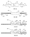
- the extracted cable fiber sections 124 A and 124 B are optically connected or optically coupled (e.g., spliced, such as fusion-spliced) at optical connections 150 A and 150 B (e.g., splices as shown) to respective tether fibers 12 A and 12 B.
- portions of tether fibers 12 A and 12 B are then enclosed in respective tether covers 135 A and 135 B to form respective tethers 134 A and 134 B that extend along fiber-optic cable 120 in opposite (e.g., upstream and downstream) directions.
- Tether fibers can be, for example, standard cable fibers such as Corning SMF-28, available from Corning, Inc., Corning, N.Y.
- FIG. 5C is similar to FIG. 5B and illustrates an example embodiment that includes a single tether cover 135 that extends in both directions along fiber-optic cable 120 and that covers both tether fibers 12 A and 12 B.
- Tether cover 135 includes an opening 139 through which tether fibers 12 A and 12 B (or cable fibers 124 A and 124 B, as the case may be depending on the location of uplink and downlink splices 150 A and 150 B) are inserted.
- Tether cover has an inside diameter d T .
- FIGS. 5D-5F are similar to FIGS. 5A-5C , but illustrate example embodiments wherein the cable fiber sections 124 A and 124 B constitute the tether fibers rather than using separate tether fibers.
- Example embodiment illustrated by FIG. 5D shows a tether comprised of two cable fibers and a common tether cover.
- Example embodiment illustrated by FIG. 5E shows two cable fibers exiting in separate directions and extending into separate tether covers.
- Example embodiment illustrated by FIG. 5F shows two cable fibers exiting in separate directions and extending into a common cover.
- FIG. 5D-5F are similar to FIGS. 5A-5C , but illustrate example embodiments wherein the cable fiber sections 124 A and 124 B constitute the tether fibers rather than using separate tether fibers.
- Example embodiment illustrated by FIG. 5D shows a tether comprised of two cable fibers and a common tether cover.
- Example embodiment illustrated by FIG. 5E shows two cable fibers exiting in separate directions and
- one cable fiber section e.g., section 124 A
- one separate tether fiber 12 B that is optically connected to cable fiber section 125 B
- ribbon fiber cables such as RPXTM can have one or more fibers accessed by conventional remote ribbon access tools.
- the fibers can be combined, within the tether, in any desired configuration to be connectorized at the tether distal end with at least one multifiber connector, though some instances of single fiber connectors on tethers from ribbon fiber cables are possible.
- FIG. 6A is a schematic side view of the bi-directional tap assembly 130 of FIG. 5B or FIG. 5C , wherein the tap is covered by a protective cover 160 , such as an overmolded portion or a clam-shell-type housing.
- protective cover 160 is formed by an overmolding process that includes preparing the sheath of the distribution cable, such as by cleaning and roughening, flame preparing or chemically preparing the surface. The assembly is placed into an overmolding tool and a flowable overmolding material is introduced into a mold cavity defined by the molding tool.
- the final overmold preferably has a low profile, e.g., an outer diameter do sufficiently small to allow the assembly to be installed in buried and aerial networks through any conduit or duct less than 5 inches in breadth, or over aerial installation sheave wheels and pulleys.
- a low profile e.g., an outer diameter do sufficiently small to allow the assembly to be installed in buried and aerial networks through any conduit or duct less than 5 inches in breadth, or over aerial installation sheave wheels and pulleys.
- Intrinsic properties of the overmold material contribute to its flexibility, and in some embodiments, the geometric shape of the overmold and the positioning of strength components and bend elements within contribute to controlled stiffness.
- overmold diameter do is sized so that bi-directional tap assembly 130 can fit through apertures of 1.25′′ in diameter.
- tethers 134 A and 134 B include a connectorized (e.g., pre-connectorized) distal end 137 A and 137 B having respective connectors 138 (i.e., 138 A and 138 B such as a single fiber connector, duplex connector or multi-fiber connector.
- connectors 138 include 4-fiber, 6-fiber, 8-fiber and 12-fiber connectors.
- connectors 138 A and 138 B are configured to connect tethers 134 A and 134 B to an external device 140 .
- FIG. 6B is similar to FIG. 6A and illustrates another example embodiment wherein tethers 134 A and 134 B are connectorized.
- FIG. 6C is a schematic diagram similar to FIG. 6B and illustrates an example embodiment of bi-directional tap assembly 130 wherein the assembly includes a protective cover 160 in the form of an overmolded shell.
- Protective cover 160 contains tether fibers 12 A and 12 B connected to respective cable fiber sections 124 A and 124 B (not shown; see, e.g., FIG. 5A ).
- Tether fibers 12 A and 12 B are terminated with an adapter 163 that at least partially extends from protective cover 160 .
- Tether 134 with a connector 139 at tether proximal end 136 can then be connected to the fiber-optic cable 120 via adapter 163 .
- FIG. 6D is similar to FIG. 6C and illustrates an example embodiment wherein the fibers within protective cover 160 and connected to adapter 163 are cable fiber sections 124 A and 124 B (see also FIG. 5D ).
- Example adapter configurations similar to those illustrated in FIG. 6C and 6D , are described in U.S. patent application Ser. No. 11/888,220, published as U.S. 2008/0019641 and entitled “PRE-CONNECTORIZED FIBER OPTIC DISTRIBUTION CABLE HAVING OVERMOLDED ACCESS LOCATION,” is hereby incorporated by reference.
- An example method for connecting tethers 134 A and 134 B and the tether fibers 12 A and 12 B therein to fiber-optic cable 120 and respective cable fiber sections 124 A and 124 B therein involves exposing the appropriate buffer tube 125 A and 125 B and forming therein the aforementioned upstream and downstream access points 129 A and 129 B about 12′′ apart. Individual cable fiber sections 124 A and 124 B are then cut at the second buffer tube opening 129 B and pulled out of the buffer tube at the first tube opening 129 A. The downstream and upstream cable fiber sections 124 A and 124 B are then optically connected (e.g., spliced) to the respective upstream and downstream tether fibers 12 A and 12 B.
- a length of fiber-optic cable 120 is exposed to create an exposed region 128 large enough to allow for three openings to be made in the buffer tube: upstream and downstream openings or access points 129 A and 129 B, and a mid-point opening or access point (not shown) between the upstream and downstream access points.
- These openings can be, for example, about 10′′ apart, in which case an additional 10′′ of cable needs to be opened as compared to using just two access points 129 A and 129 B.
- the mid-point opening point is used to cut the fiber, and the upstream and downstream openings 129 A and 129 B are used to pull the upstream and downstream cable fiber sections 124 A and 124 B out of the buffer tube 125 in both directions.
- protective cover 160 can be relatively compact and have a relatively low profile with respect to fiber-optic cable 120 . This is important in fiber-optic cable deployment in situations where fiber-optic cable and bi-directional taps 130 need to be fed through small openings or stored on take-up reels, as discussed above.
- cable fibers 124 and/or tether fibers 12 are ribbonized to form one or more ribbonized tethers 134 A and/or 134 B.
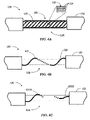
- FIG. 7A is a schematic side view of another example embodiment of a bi-directional tap 130 that includes a single tether 134 along a length of the fiber-optic cable 120 and that includes both “upstream” and “downstream” tether fibers, as discussed below.
- Bi-directional tap 130 of FIG. 7A includes protective cover 160 that covers the tether-fiber to cable-fiber splices at tap point 128 as also discussed in greater detail below.
- tether 134 C runs through cover 160 , with one end connected to a translatable mount 210 that is slideably mounted to fiber-optic cable 120 .
- tether 134 is connectorized as tether end 137 with a connector 138 .
- FIG. 7B is similar to FIG. 7A , and shows a fiber cut location 205 where the select cable fibers 124 can be accessed and cut using a fiber access tool so that the cable fiber sections can be spliced at mid-span access point 128 .
- FIG. 8 is a close-up partial cut-away view of the bi-directional tap assembly 130 of FIGS. 7A-7C .
- Tether fibers 12 A and 12 B are contained in tether cover 135 , which in an example embodiment is in the form of a tube.
- tether fibers 12 A and 12 B are bend-performance fibers such as those discussed in detail above, meaning that they can each have respective tight bends 55 A and 55 B (e.g., as small as a 5 mm bend radius or a bend diameter D B of 10 mm) without significant loss in transmission performance.
- the tether cover inside diameter d T defines the bend diameter D B .
- Tether fibers 12 A and 12 B initially lead away from tap point 128 in one direction and include respective bends 55 A and 55 B having a bend angle ⁇ B equal to or about 180° so that the tether fibers bend back on themselves and travel within tether cover 135 in the opposite direction back toward the tap point.
- bends 55 A and 55 B also move back and forth within tether cover 135 , allowing the tether fibers 12 A and 12 B to coil and re-coil as the tether is so moved.
- FIG. 9 is a close-up schematic perspective view of tether fibers 12 A and 12 B illustrating an example embodiment wherein the tether fibers are in the form of ribbon fibers having a common bend 55 .
- fiber-optic cable 120 is a ribbon-type cable, such as Corning SST® ribbon cable available from Corning, Inc., Corning, N.Y.
- the first step includes preparing tether 134 such that there is an extra length for all of the tether fibers 12 to be connected to their respective cable fiber sections 124 . This extra length may be, for example, approximately 3′′.
- the next step includes forming the needed number of cable fiber sections 124 (e.g., 124 A and 124 B) from one or more buffer tubes 125 , as described above.
- the next step includes identifying one or more tether fibers 12 to be connected to the corresponding one or more cable fiber sections 124 .
- the next step includes optically connecting (e.g., splicing) the one or more cable fiber sections 124 (e.g., 124 A and 124 B) to the one or more tether fibers 12 (e.g., 12 A and 12 B) thereby forming corresponding optical connections 150 (e.g., splices 150 A and 150 B).
- the next step includes looping each spliced cable-fiber/tether-fiber pair so that optical connections 150 reside between the respective loops (e.g., bends 55 A and 55 B) and downstream access points 129 (e.g., 129 A and 129 B). Bends 55 are formed in the bend-resistant tether fibers 12 rather than in the corresponding cable fibers 124 .
- tether cover 134 is protected from the effects of offset bend radii by translatable mount 210 , which is translated along fiber-optic cable 120 ; bends 55 in tether fibers 12 travel along the length of the fiber-optic cable as well, as described above.
- the total number of cable fibers 124 being accessed is six or less (meaning total of 12 or less fibers passing through the tether), they can be connected into a single MT style multifiber connecter 138 . If more than six fibers are being accessed, then the cable fibers from each direction of the cable can be put into their own tether (two tethers from one tap point, each with its own connector terminal).
- one tap point might access a first subset of optical fibers (e.g., fibers 1 - 4 ) from the upstream direction, and a second subset of optical fibers (e.g. fibers 5 - 8 ) from the downstream direction.
- a third subset of optical fibers e.g. fibers 9 - 12
- the optical fibers of the first subset are dark, but each fiber can be accessed in a subsequent tap point from the downstream direction.
- the fibers of the second subset can be accessed upstream of the original tap point, creating a tether location and utilizing, from both directions, full use of both the first and second fiber subsets, with direct or indirect communication with the central office by virtue of the bi-directionality of the system.
- the above-described protective cover 160 is or includes an overmold.
- the overmold is preferably flexible so that when it is combined with a flexible fiber-optic cable, it provides a flexible tap assembly that is durable yet sufficiently flexible so as to permit installation using known installation methods and equipment.
- a flexible overmold is bendable and twistable and may be installed around installation pulleys and within a small diameter conduit while maintaining structural integrity, sealing, and optical and mechanical performance.
- An exemplary overmolding process includes: (i) arranging portions of the tap assembly about a network access point in, for example, a cavity made by a molding tool, die or die-casting; (ii) introducing a curable material in fluid form into the cavity, the fluid essentially flooding the cavity, penetrating interstices around and about the assembly, and essentially covering the assembly; and (iii) curing the curable material within suitable curing conditions.
- Exemplary molding processes include, but are not limited to, pour and injection molding, pressure molding, and die casting.
- Alternative exemplary processes may include vacuum and heat forming processes.
- the overmold can be applied by extruding a flexible closure material while pulling the assembly through a die.
- the overmold is preferably a monolithic form.
- Beneath the overmold material may be disposed a flexible cover material, for example a paper, plastic, tape or wrapping material, to cover at least a portion of the assembly prior to applying the molding material so that the material will not directly contact components.
- the molding material may directly contact the underlying components.
- an integral mesh (not shown) is used in combination with the overmold to prevent cracking of the overmold.
- Exemplary overmold materials may include polyurethanes, silicones, thermoplastics, thermosets, elastomers, UV curable materials and like materials taken alone or in combination.
- the overmold may further include additives, plasticizers, flame retardant additives, dyes and colorants. Overmold flexibility and crush-resistance may be enhanced or relaxed based upon application.
- curable may include thermoplastic hardening, chemical additive curing, catalyst curing including energy curing as by heat or light energy, and phase changes.
- the overmold can also be formed using heat-shrink tubing.
- the overmold can be bent with a force about equal to the force required to bend the fiber-optic cable itself (the cable to which the overmold is attached) without the overmold attached.
Landscapes
- Physics & Mathematics (AREA)
- General Physics & Mathematics (AREA)
- Optics & Photonics (AREA)
- Light Guides In General And Applications Therefor (AREA)
Abstract
Description
- The present application is related to U.S. patent application Ser. No. ______, entitled “BI-DIRECTIONAL CABLE ASSEMBLY WITH BEND-IMPROVED FIBER TETHER,” filed Nov. 7, 2008, docket number HI08-010.
- 1. Technical Field
- The present invention relates generally to fiber-optic cables used in telecommunication systems, and in particular relates to bi-directional tap assemblies arranged at mid-span access locations of two-way fiber topologies.
- 2. Technical Background
- Optical fiber is used for a variety of broadband telecommunication applications that involve voice, video and/or data transmissions. Such fiber-based telecommunication systems utilize fiber-optic cables (e.g., “distribution cables”) that include a number of mid-span access locations at which one or more optical fibers are terminated and interconnected with a branch cable or a drop cable. The mid-span access locations provide an interconnection point, also referred to as “access point” or “tap point” (or just “tap” for short) from the distribution cable. The interconnection point can include a tap assembly that connects optical fibers in the distribution cable to another location, such as another network distribution cable or termination point, or directly to an end user, commonly referred to as a subscriber, thereby extending an “all optical” communications network closer to the subscriber. In this regard, fiber optic networks are being developed that deliver “fiber-to-the-curb” (FTTC), “fiber-to-the-business” (FTTB), “fiber-to-the-home” (FTTH), or “fiber-to-the-premises” (FTTP), referred to generically as “FTTx.”
- Tap assemblies are common for one-way fiber topologies wherein optical signals travel in a single direction. Such taps are typically formed by accessing an optical fiber in a fiber optical cable and cutting the fiber to form two fiber sections. One of the fiber sections is terminated (e.g., spliced to a connectorized section of optical fiber) to form the tap, while the other section of the fiber becomes “dark fiber” because it is not utilized in the one-way topology. This approach, however, cannot be used for two-way fiber topologies because the fibers carry signals in two directions. This means that one section of the fiber cannot be disregarded in forming the tap.
- In accordance with embodiments broadly described herein, a bi-directional tap assembly includes at least one short length of cable, referred to herein as a “tether.” The tether is attached (e.g., spliced or otherwise optically connected) to an optical fiber of a fiber optical cable at a mid-span location. The mid-span location is also referred to as a “tap point.” The bi-directionality of the tap assembly means that at least one “upstream” and at least one “downstream” optical fiber is accessed at the tap point, wherein “upstream” and “downstream” are relative terms used to indicate direction in which information travels over the fiber-optic cable from one or more reference locations, such as a central office or other types of communications management centers or telecommunication devices. In a bi-directional fiber system topology, a single optical fiber carries optical signals in both directions.
- Bi-directionality is associated with a ring network topology where a fiber-optic cable begins and ends at the same location, e.g., a central office. Bi-directionality also is associated with a non-ring topology where ends of a distribution cable terminate at respective locations that transmit and receive information over the distribution cable. In a bi-directional telecommunications system, at least one optical fiber in the system is configured to carry optical signals in two directions.
- The tether of the tap assembly permits at least one connector to be positioned at a desired location in a fiber optic communications network. In an example embodiment, the tether is manufactured in the factory and spliced or otherwise optically connected in the field to a previously installed fiber optic distribution cable. Alternatively, the tap assembly (including a tether and at least one connector) is manufactured in the factory (i.e., factory-prepared) for a pre-engineered fiber optic communications network and wound onto a cable reel for deployment in the field.
- While a tether can be of any length, in practice it typically provides a relatively short length of cable (as compared to the distribution cable) to allow a distribution or termination point to be positioned at a desired location. Thus, in various example embodiments, the tether has a length up to about 100 feet, more especially about 25 feet, and preferably a length of about 12 to about 15 feet. The tether eliminates the need for absolute accuracy in the engineering of the fiber optic network, the manufacture of the distribution tap assembly and the deployment of the distribution tap assembly. In example embodiments, the tap assembly includes two tethers: an upstream tether and a downstream tether.
- The ends of the one or more optical fibers of the tether (“tether optical fibers”) can be connectorized with a tether connector, such as with one of the following connector types: SC, LC, DC, FC, ST, SC/DC, MT, MT-RJ, MTP, MPO. Other like single or multi-fiber connectors now known or hereafter developed can also be used.
- Accordingly, a first aspect of the invention is a bi-directional tap assembly that includes a fiber-optic cable having at least one cable optical fiber. The cable optical fiber is adapted to carry bi-directional optical signals and is preterminated at a mid-span location to form a first cable fiber section having a first cable fiber end and a second cable fiber section having a second cable fiber end. The bi-directional tap assembly can include at least one tether formed at both cable fiber sections, from one cable fiber section and one tether fiber, or from tether fibers optically connected to the respective cable fiber sections.
- A second aspect of the invention is a method of forming a bi-directional tap in a fiber-optic cable that includes at least one cable optical fiber. The method includes preterminating, at a mid-span location, the at least one cable optical fiber to form corresponding at least one first and at least one second cable fiber sections having respective first and second cable fiber ends. The method also includes optically coupling the at least one first and the at least one second cable fiber sections at their respective first and second cable fiber ends to respective at least one first and at least one second tether fibers. An example embodiment of the method includes performing the above acts of the method prior to deploying the cable.
- A third aspect of the invention is the combination of accessed fibers. In a multifiber cable, whether a ribbon fiber cable or a loose tube cable, one particular tap point might access fibers ribers 1-4 from the upstream direction and fibers 5-8 from the downstream direction, leaving fibers 9-12 as express fibers, for example. Downstream, therefore, fibers 1-4 are “dark”, but can be accessed in a subsequent tap point from the downstream direction. Conversely, fibers 5-8 can be accessed upstream of the original tap point, creating a tether location and utilizing, from both directions, the full use of fibers 1-8, with direct or indirect communication with the central office by virtue of the “bi-directionality” of the technology. While all combinations of accessing fibers are exhaustive and not specifically covered by this invention, they are within the scope of the technology covered by this invention.
- Additional features and advantages will be set forth in the detailed description that follows, and in part will be readily apparent to those skilled in the art from that description or recognized by practicing the invention as described herein, including the detailed description that follows, the claims, as well as the appended drawings.
- It is to be understood that both the foregoing general description and the following detailed description present embodiments of the invention, and are intended to provide an overview or framework for understanding the nature and character of the invention as it is claimed. The accompanying drawings are included to provide a further understanding of the invention, and are incorporated into and constitute a part of this specification. The drawings illustrate various embodiments of the invention, and together with the description, serve to explain the principles and operations of the invention.
-
FIG. 1 is a schematic side view of a section of an example embodiment of a bend-insensitive optical fiber in the form of a nanostructure optical fiber; -
FIG. 2A is a schematic diagram of an example cross-section of the optical fiber ofFIG. 1 as viewed along thedirection 2A-2A; -
FIG. 2B is a schematic diagram illustrating the bend angle 0B and the bend diameter DB of a bend formed in the bend-insensitive optical fiber ofFIG. 1 ; -
FIG. 3A is a schematic diagram of a bi-directional telecommunication system having a ring-topology and that includes a fiber-optic cable with two bi-directional tap assemblies arranged at respective mid-span access locations; -
FIG. 3B is a close-up view of a connectorized embodiment of one of the tethers ofFIG. 3A ; -
FIG. 3C is a schematic diagram of a linear bi-directional telecommunication system that includes a fiber-optic cable with a single bi-directional tap assembly arranged at a mid-span access location; -
FIG. 4A is a schematic close-up side view of a stripped section of an example fiber-optic cable showing a twisted array of buffer tubes carried by the cable; -
FIG. 4B is essentially the same asFIG. 4A but showing only one of the buffer tubes for the sake of illustration; -
FIG. 4C is similar toFIG. 4B , but showing sections of two different buffer tubes; -
FIG. 5A is similar toFIG. 4C , but illustrating two tether fibers spliced to respective cable fiber ends; -
FIG. 5B is similar toFIG. 5A , and illustrates the tether fibers contained in respective tether covers to form respective tethers; -
FIG. 5C is similar toFIG. 5B , and illustrates an example embodiment that includes a single tether cover that extends along the fiber-optic cable and that is used to contain the tether fibers and form two tethers; -
FIGS. 5D-5F are similar toFIGS. 5A-5C , but illustrate example embodiments wherein the cable fiber sections are used to form the tether; -
FIG. 5G is a schematic diagram similar toFIG. 5D , illustrating an example embodiment wherein the tether is formed from one cable fiber section and one tether fiber; -
FIG. 6A is a schematic side view of the bi-directional tap assembly ofFIG. 5B orFIG. 5C , wherein the assembly includes a low-profile protective cover, with the two tethers passing through respective sides of the protective cover to run along the fiber-optic cable in opposite directions; -
FIG. 6B is a schematic side view similar toFIG. 6A , showing connectorized tethers; -
FIG. 6C is a schematic diagram similar toFIG. 6B and illustrates an example embodiment of the bi-directional tap assembly that includes an adapter for connecting to a connectorized tether; -
FIG. 6D is similar toFIG. 6C and illustrates an example embodiment wherein the cable fiber sections are connected directly to the adapter; -
FIG. 7A is a schematic side view of another example embodiment of a bi-directional tap that includes a single tether that is translatable along the length of the fiber-optic cable; -
FIG. 7B is similar toFIG. 7A , and shows a fiber cut location where the select cable fibers can be accessed and cut using a fiber access tool; -
FIG. 8 is a close-up partial cut-away view of thebi-directional tap assembly 130 ofFIGS. 7A-7C , showing the 180° bend in the two tether fibers; and -
FIG. 9 is a close-up schematic perspective view of the tether fibers in the form of ribbon fibers having a common bend. - Reference is now made in detail to the present embodiments of the invention, examples of which are illustrated in the accompanying drawings. Whenever possible, the same reference numbers and symbols are used throughout the drawings to refer to the same or like parts. For example, bend-insensitive fibers and tether fibers use the
same reference number 12 for convenience even though the tether fiber need not be a bend-insensitive fiber in all example embodiments. In the drawings and in the description below, a signal traveling from upstream to downstream is referred to as a “downstream signal,” and a signal traveling from downstream to upstream is referred to as an “upstream signal.” - Various embodiments of bi-directional tap assemblies for two-directional fiber topologies are disclosed. The embodiments shown include a protective cover, such as an overmold, for substantially sealing an exposed portion of the cable created when pre-selected optical fibers are accessed through the cable sheath, are preterminated, and then are spliced to corresponding tether fibers. The term “preterminated” is used herein to refer to an optical fiber that is terminated at a point short of its total installed length. In the various embodiments described herein, the bi-directional tap assembly of the present invention includes a fiber optic distribution cable (“fiber-optic cable”) comprising at least a cable sheath having a predetermined number of optical fibers contained within. The predetermined number of optical fibers may be individualized, ribbonized, and/or combinations of each. The distribution cable may further comprise strength members, strength yams, one or more buffer tubes, and water-sellable tapes or foams, among other known cable components. The distribution cable may have a round or a non-round cross-section. Example fiber-optic cables suitable for use in the present invention include, but are not limited to, Altos™, SST™ and RPX™ cables available from Corning Cable Systems of Hickory, N.C. Although only one mid-span access location may be shown on a fiber-optic cable in some embodiments for the sake of illustration, the fiber-optic cable may include more than one such access location along its length for attaching multiple tethers at multiple access points. Each mid-span access location is used to access and to terminate pre-selected optical fibers within the fiber optic (distribution) cable.
- Bend-Improved Optical Fibers
- Example embodiments make use of “bend-improved” or “bend performance” optical fibers that may have varying degrees of insensitivity to bends. One type of fiber useful in the present embodiments is “bend-insensitive” fiber, such as fiber in the form of so-called “nanostructure” or “holey” optical fibers. There are a number of such fibers on the market today. Nanostructure fibers have one or more regions with periodically or a periodically arranged small holes or voids, which make the fiber extremely bend insensitive.
- Bend-insensitive fibers as used in the present invention include, for example, nanostructure fibers of the type available from Corning, Inc., of Corning, N.Y., including, but not limited to, single-mode, multi-mode, bend performance fiber, bend-optimized fiber and bend-insensitive optical fiber. Nanostructure fibers are advantageous in that they allow for the tap assemblies of the present invention to have fibers with relatively small-radius bends while optical attenuation in the fibers remains extremely low. One example of a bend-insensitive optical fiber includes a core region and a cladding region surrounding the core region, the cladding region comprising an annular hole-containing region comprised of non-periodically disposed holes such that the optical fiber is capable of single mode transmission at one or more wavelengths in one or more operating wavelength ranges. The core region and cladding region provide improved bend resistance, and single mode operation at wavelengths preferably greater than or equal to 1500 nm, in some embodiments also greater than about 1310 nm, in other embodiments also greater than 1260 nm. The optical fibers provide a mode field at a wavelength of 1310 nm greater than 8.0 μm, and preferably between about 8.0 and 10.0 μm.
- One type of nanostructure optical fiber developed by Corning, Inc. has an annular ring of non-periodic airlines (of diameter ˜1×10⁻⁷ m) that extend longitudinally along the length of the fiber. The region with the ring of airlines has a reduced apparent or average index of refraction, because air has an index of refraction of approximately 1 compared to the fused silica matrix refractive index of approximately 1.46. The ring of airlines is positioned to create a refractive index profile that enables superior bend performance (optically) and significantly smaller minimum bend radius specifications.
- According to one aspect of the invention, the tether fibers used can satisfy the requirements for G657.B, which generally requires an optical fiber to operate satisfactorily at a bend radius of 7.5 mm, or even at a bend radius of 5 mm. In this specification, fibers satisfying G657.B are described as “bend-tolerant” fibers.
-
FIG. 1 is a schematic side view of a section of an example embodiment of a bend-insensitive fiber in the form of a nanostructure optical fiber (“nanostructure fiber”) 12 having a central axis AF.FIG. 2A is a schematic cross-section ofnanostructure fiber 12 as viewed along thedirection 2A-2A inFIG. 1 .Nanostructure fiber 12 can be, for example, any one of the various types of nanostructure optical fibers, such as so-called “holey” fibers. For the purposes of the present invention, a “bend-insensitive fiber” includes nanostructure fibers that make use of periodic or non-periodic nanostructures or holes. - In an example embodiment, nanostructure
optical fiber 12 includes a core region (“core”) 20, ananostructure region 30 surrounding the core, and an outer cladding region 40 (“cladding”) surrounding the nanostructure region. Other ring-type configurations for nanostructureoptical fiber 12 are also known. A protective cover or sheath (not shown) optionally coversouter cladding 40. - In an example embodiment,
nanostructure region 30 comprises a glass matrix (“glass”) 31 having formed therein non-periodically disposed holes (also called “voids” or “airlines”) 32, such as the example voids shown in detail in the magnified inset ofFIG. 2A . In another example embodiment, voids 32 may be periodically disposed, such as in a photonic crystal optical fiber, wherein the voids typically have diameters between about 1×10⁻⁶ m and 1×10⁻⁵ m.Voids 32 may also be “non-periodic airlines.” In an example embodiment,glass 31 is fluorine-doped while in another example embodiment the glass is undoped pure silica. By “non-periodically disposed” or “non-periodic distribution,” it is meant that when one takes a cross-section of the optical fiber (such as shown inFIG. 2A ), thevoids 32 are randomly or non-periodically distributed across a portion of the fiber. - Cross sections similar to
FIG. 2A taken at different points along the length of nanostructureoptical fiber 12 will reveal different cross-sectional hole patterns, i.e., various cross-sections will have different hole patterns, wherein the distributions of holes and sizes of holes do not match. That is, the holes are non-periodic, i.e., they are not periodically disposed within the fiber structure. These holes are stretched (elongated) along the length (i.e. in a direction generally parallel to the longitudinal axis) of the optical fiber (and thus have a longer dimension along the length of the fiber), but do not extend the entire length of the entire fiber for typical lengths of transmission fiber. While not wishing to be bound by theory, it is believed that the holes extend less than a few meters, and in many cases less than 1 meter along the length of the fiber. - If non-periodically disposed holes/voids 32 are employed in
nanostructure region 30, it is desirable in one example embodiment that they be formed such that greater than 95% of and that all of the holes exhibit a mean hole size in the cladding for the optical fiber which is less than 1550 nm, especially less than 775 nm, and preferably less than about 390 nm. Likewise, the maximum diameter of the holes in the fiber is less than 7000 nm, especially less than 2000 nm, and preferably less than 1550 nm, and most preferably less than 775 nm. In some embodiments, the fibers disclosed herein have fewer than 5000 holes, in some embodiments also fewer than 1000 holes, and in other embodiments the total number of holes is fewer than 500 holes in a given optical fiber perpendicular cross-section. The fibers disclosed in this specification may exhibit combinations of these characteristics. - According to one embodiment, an optical fiber exhibits fewer than 200 holes in the optical fiber, the holes having a maximum diameter less than 1550 nm and a mean diameter less than 775 nm, although useful and bend resistant optical fibers can be achieved using larger and greater numbers of holes. The hole number, mean diameter, max diameter, and total void area percent of holes can all be calculated with the help of a scanning electron microscope at a magnification of about 800× to about 4000× and image analysis software, such as ImagePro, which is available from Media Cybernetics, Inc. of Silver Spring, Md., USA.
- In an example embodiment, holes/voids 32 can contain one or more gases, such as argon, nitrogen, or oxygen, or the holes can contain a vacuum with substantially no gas; regardless of the presence or absence of any gas, the refractive index of the hole-containing region is lowered due to the presence of the holes. The holes can be periodically or non-periodically disposed. In some embodiments, the plurality of holes comprises a plurality of non-periodically disposed holes and a plurality of periodically disposed holes. Alternatively, or in addition, as mentioned above the depressed index can also be provided by downdoping the glass in the hole-containing region (such as with fluorine) or updoping one or both of the surrounding regions.
-
Nanostructure region 30 can be made by methods that utilize preform consolidation conditions, which are effective at trapping significant amounts of gases in the consolidated glass blank, thereby causing the formation of voids in the consolidated glass optical fiber preform. Rather than taking steps to remove these voids, the resultant preform is used to form an optical fiber with voids, or holes, therein. As used herein, the diameter of a hole is the longest line segment whose end points are disposed on the silica internal surface defining the hole when the optical fiber is viewed in a perpendicular cross-section transverse to the optical fiber central axis AF. - SEM analysis of the end face of an example nanostructure
optical fiber 12 showed an approximately 4.5-micron radius GeO2—SiO2 void-free core (having an index of approximately +0.34 percent delta versus silica) surrounded by an 11-micron outer radius void-free near clad region surrounded by 14.3-micron outer radius non-periodic void-containing cladding region (ring thickness of approximately 3.3 μm), which is surrounded by a void-free pure silica outer cladding having an outer diameter of about 125 μm (all radial dimensions measured from the center of the optical fiber). - The
nanostructure region 30 comprised approximately 2.5 percent regional area percent holes (100% N2 by volume) in that area with an average diameter of 0.28 μm and the smallest diameter holes at 0.17 μm and a maximum diameter of 0.48 μm, resulting in a total of about 130 holes in the fiber cross-section. The total fiber void area percent (area of the holes divided by the total area of the optical fiber cross-section×100) was about 0.05 percent. Optical properties for this fiber were 0.36 and 0.20 dB/Km at 1310 and 1550 nm, respectively, and a 22-meter fiber cable cut-off of about 1250 nm, thereby making the fiber single mode at wavelengths above 1250 nm. - The nanostructure optical fibers used herein may or may not include germania or fluorine to adjust the refractive index of the core and/or cladding of the optical fiber, but these dopants can also be avoided in the intermediate annular region and instead, the holes (in combination with any gas or gases that may be disposed within the holes) can be used to adjust the manner in which light is guided down the fiber core. The
nanostructure region 30 may consist of undoped (pure) silica, thereby completely avoiding the use of any dopants in the hole-containing region, to achieve a decreased refractive index, or the nanostructure region may comprise doped silica, e.g. fluorine-doped silica having a plurality of holes. In one set of embodiments, the core includes doped silica to provide a positive refractive index relative to pure silica, e.g. germania doped silica. The core region is preferably hole-free. - Such fiber can be made to exhibit a fiber cut-off of less than 1400 nm, more preferably less than 1310 nm, a 20-mm macrobend induced loss at 1550 nm of less than 1 dB/turn, preferably less than 0.5 dB/turn, even more preferably less than 0.1 dB/turn, still more preferably less than 0.05 dB/turn, yet more preferably less than 0.03 dB/turn, and even still more preferably less than 0.02 dB/turn, a 12-mm macrobend induced loss at 1550 nm of less than 5 dB/turn, preferably less than 1 dB/turn, more preferably less than 0.5 dB/turn, even more preferably less than 0.2 dB/turn, still more preferably less than 0.01 dB/turn, still even more preferably less than 0.05 dB/turn, and an 8-mm macrobend induced loss at 1550 nm of less than 5 dB/turn, preferably less than 1 dB/turn, more preferably less than 0.5 dB/turn, and even more preferably less than 0.2 dB/turn, and still even more preferably less than 0.1 dB/turn.
- The nanostructure fibers used herein may be multimode. Such fibers may comprise, for example, a graded-index core region and a cladding region surrounding and directly adjacent to the core region, the cladding region comprising a depressed-index annular portion comprising a depressed relative refractive index, relative to another portion of the cladding (which preferably is silica which is not doped with an index of refraction altering dopant such as germania or fluorine). Preferably, the refractive index profile of the core has a parabolic shape. The depressed-index annular portion may comprise glass comprising a plurality of holes, fluorine-doped glass, or fluorine-doped glass comprising a plurality of holes. The depressed index region can be adjacent to or spaced apart from the core region.
- In an example embodiment, the multimode nanostructure optical fiber exhibits very low bend-induced attenuation, in particular very low macrobending. In some embodiments, high bandwidth is provided by low maximum relative refractive index in the core, and low bend losses are also provided. In some embodiments, the core radius is large (e.g. greater than 20 μm), the core refractive index is low (e.g. less than 1.0%), and the bend losses are low. In an example embodiment, the multimode nanostructure optical fiber exhibits a spectral attenuation of less than 3 dB/km at 850 nm.
- In an example embodiment, the numerical aperture (NA) of the nanostructure optical fiber used herein is preferably greater than the NA of the optical source directing signals into the fiber; for example, the NA of the optical fiber is preferably greater than the NA of a VCSEL light source. The bandwidth of the multimode optical fiber varies inversely with the square of Δ1MAX. For example, a multimode optical fiber with Δ1MAX of 0.5% can yield a bandwidth 16 times greater than an otherwise identical multimode optical fiber except having a core with Δ1MAX of 2.0%. In some embodiments, the core extends radially outwardly from the centerline to a radius R1, wherein 12.5 μm≦R1≦40 μm. In some embodiments, 25 μm≦R1≦32.5 μm, and in some of these embodiments, R1 is greater than or equal to about 25 μm and less than or equal to about 31.25 μm. The core preferably has a maximum relative refractive index less than or equal to 1.0%. In other embodiments, the core has a maximum relative refractive index less than or equal to 0.5%. Such multimode fibers preferably exhibit a 1-turn 10 mm diameter mandrel attenuation increase of no more than 1.0 dB, preferably no more than 0.5 dB, more preferably no more than 0.25 dB, even more preferably no more than 0.1 dB, and still more preferably no more than 0.05 dB, at all wavelengths between 800 and 1400 nm.
- Fiber Bend Angle and Bend Diameter
-
FIG. 2B is a schematic diagram illustrating a bend angle θB and a bend diameter DB of an example bend-insensitive optical fiber in the form ofnanostructure fiber 12 having abend 55 formed therein. Bend diameter DB is twice the bend radius RB. Two arrows AR1 and AR2 represent the relative orientations (directions) ofoptical fiber 12 on either side ofbend 55. Bend angle θB is defined by the intersection of arrows AR1 and AR2, as shown in the right-hand side ofFIG. 2B . Because sections of optical fiber do not always remain perfectly straight before and after a bend, the bend angle θB is not exact, but serves as a useful approximation that generally describes the degree to whichnanostructure fiber 12 is bent. - In example embodiments discussed below, a bend angle θB described as being “equal to or about equal to 180°” is used to describe a bend wherein the fiber doubles back on itself Such examples are discussed below in connection with
FIG. 8 , which shows an idealized example of abend - Telecommunication System with Bi-Directional Tap Assembly
-
FIG. 3A is a schematic diagram of anexample telecommunication system 100 having acentral station 110 that includes two transmitting/receiving (T/R)units System 100 includes a fiber-optic cable 120 (e.g., a distribution cable) having first and second ends 120A and 120B respectively optically coupled to uplink and downlink T/R units optic cable 120 carries a number of optical fibers 124 (not shown inFIG. 3A ; seeFIG. 4A ). These fibers are referred to herein as “cable fibers.” Optical signals carried by cable fibers can travel fromcentral station 110 in both directions as uplink and downlink signals SA and SB, as shown. Note that uplink signal SA travels toward uplink T/R unit 112A and downlink signal SB travels toward downlink T/R unit 112B. - According to one aspect,
cable 120 includes at least onebi-directional tap assembly 130. Various embodiments ofbi-directional tap assembly 130 are discussed in greater detail below. Twobi-directional tap assemblies 130 at two different mid-span locations are shown inFIG. 3A for the sake of illustration. Eachtap assembly 130 includes a protective cover 160 (discussed below), anupstream tether 134A that includes one or more upstream tether fiber sections (“tether fibers”) 12A and adownstream tether 134B that includes one or moredownstream tether fibers 12B. In an example embodiment, one or both oftethers FIG. 3B is a close-up view of a connectorizedupstream tether 134 that has aproximal end 136, adistal end 137, and aconnector 138 at tetherdistal end 137. In alternate example embodiments discussed below, the tether fibers are formed from sections ofcable fibers 124 carried by fiber-optic cable 120. - In an example embodiment,
bi-directional telecommunication system 100 further includes at least oneexternal device 140 optically coupled to at least one oftethers External device 140 may be, for example, a traffic-monitoring device that produces traffic monitoring data in the form of optical data signals provided tocentral station 110 viaoptical fiber tethers optic cable 120.External device 140 may also be adapted to receive command signals fromcentral station 110, as well as signals from anotherexternal device 140.External device 140 may also be, for example, a single-port or multi-port connection terminal. -
FIG. 3C is a schematic diagram of an example embodiment of anotherbi-directional telecommunication system 100 that utilizes a linear topology.System 100 ofFIG. 3C includes two end-stations R units R units optic cable 120. A singlebi-directional tap assembly 130 at one mid-span location is shown by way of illustration. Upstream and downstream T/R units bi-directional tap assembly 130, as described in greater detail below. - First Example Bi-Directional Tap
- Now described is a method of forming a first example embodiment of
bi-directional tap assembly 130 according to the present invention.FIG. 4A is a schematic close-up view of amid-span section 200 of an example fiber-optic cable 120 having formed therein an exposedregion 128 at a mid-span location. Fiber-optic cable 120 as shown is a loose-tube cable that includes an outer cover orsheath 122 and a number ofcable fibers 124 contained in helically strandedbuffer tubes 125, as shown in the inset. Eachbuffer tube 125 contains one ormore cable fibers 124. Cable fibers can be, for example, cable fibers such as Corning SMF-28, available from Corning, Inc., Corning, N.Y. -
FIG. 4B is essentially the same asFIG. 4A but shows only onebuffer tube 125 for ease of illustration.FIG. 4C showsbuffer tube sections cable fibers 124 can be taken either from the same buffer tube or from different buffer tubes, depending on the particular application. -
Bi-directional tap 130 is formed by removing a portion of outer cover (sheath) 122 at one or more mid-span access locations to create corresponding one or more exposedregions 128, whereinbuffer tubes 125 andcable fibers 124 therein can be accessed. In an example embodiment, at least onecable fiber 124 carries optical signals that travel in both the upstream and downstream directions. -
FIGS. 5A-5C illustrate example embodiments of forming abi-directional tap 130. To createbi-directional tap 130, abuffer tube 125 that carriescable fiber 124 is identified in exposedregion 128 as described above and as shown inFIG. 4A throughFIG. 4C . In an example embodiment wherecable fibers 124 are taken from a single buffer tube, theparticular buffer tube 125 is identified and then partially extracted from the bundle of buffer tubes carried by fiber-optic cable 120.Cable fiber sections buffer tube 125 at one or more access points, such asrespective access points - In an example embodiment, the process of extracting
cable fiber sections buffer tube 125 to cutfiber 124 therein so that it can be extracted from the access point. To create an access point on a cable containing at least one buffer tube, an appropriate buffer tube may be accessed in multiple places using a standard No-Slack Optical Fiber Access Tool (NOFAT) available from Corning Cable Systems LLC of Hickory, N.C. The NOFAT tool is suitable for use in locations in which a limited amount of cable slack can be obtained and the buffer tubes remain helically wrapped around a central member. - Extracted
cable fiber sections optical fiber 124 is preterminated to form the cable fiber sections, the otheruncut cable fibers 124 remain intact and continue through the distribution cable, possibly being preterminated at another access point. In some embodiments, a water-blocking wrap and/or a protective layer may be added around the access location prior to forming the protective cover, as described below. - In an example embodiment illustrated in
FIG. 5A , the extractedcable fiber sections optical connections respective tether fibers FIG. 5B , portions oftether fibers respective tethers optic cable 120 in opposite (e.g., upstream and downstream) directions. Tether fibers can be, for example, standard cable fibers such as Corning SMF-28, available from Corning, Inc., Corning, N.Y. -
FIG. 5C is similar toFIG. 5B and illustrates an example embodiment that includes asingle tether cover 135 that extends in both directions along fiber-optic cable 120 and that covers bothtether fibers Tether cover 135 includes anopening 139 through whichtether fibers cable fibers -
FIGS. 5D-5F are similar toFIGS. 5A-5C , but illustrate example embodiments wherein thecable fiber sections FIG. 5D shows a tether comprised of two cable fibers and a common tether cover. Example embodiment illustrated byFIG. 5E shows two cable fibers exiting in separate directions and extending into separate tether covers. Example embodiment illustrated byFIG. 5F shows two cable fibers exiting in separate directions and extending into a common cover. In another example embodiment illustrated inFIG. 5G , one cable fiber section (e.g.,section 124A), and oneseparate tether fiber 12B that is optically connected tocable fiber section 125B, are used to formtether 134. In other embodiments (not shown), ribbon fiber cables such as RPX™ can have one or more fibers accessed by conventional remote ribbon access tools. The fibers can be combined, within the tether, in any desired configuration to be connectorized at the tether distal end with at least one multifiber connector, though some instances of single fiber connectors on tethers from ribbon fiber cables are possible. -
FIG. 6A is a schematic side view of thebi-directional tap assembly 130 ofFIG. 5B orFIG. 5C , wherein the tap is covered by aprotective cover 160, such as an overmolded portion or a clam-shell-type housing. In an example embodiment,protective cover 160 is formed by an overmolding process that includes preparing the sheath of the distribution cable, such as by cleaning and roughening, flame preparing or chemically preparing the surface. The assembly is placed into an overmolding tool and a flowable overmolding material is introduced into a mold cavity defined by the molding tool. The final overmold preferably has a low profile, e.g., an outer diameter do sufficiently small to allow the assembly to be installed in buried and aerial networks through any conduit or duct less than 5 inches in breadth, or over aerial installation sheave wheels and pulleys. Intrinsic properties of the overmold material contribute to its flexibility, and in some embodiments, the geometric shape of the overmold and the positioning of strength components and bend elements within contribute to controlled stiffness. In an exemplary embodiment, overmold diameter do is sized so thatbi-directional tap assembly 130 can fit through apertures of 1.25″ in diameter. - As discussed above, in an example embodiment, one or both of
tethers multi-fiber connectors 138 include 4-fiber, 6-fiber, 8-fiber and 12-fiber connectors. In an example embodiment,connectors tethers external device 140.FIG. 6B is similar toFIG. 6A and illustrates another example embodiment whereintethers -
FIG. 6C is a schematic diagram similar toFIG. 6B and illustrates an example embodiment ofbi-directional tap assembly 130 wherein the assembly includes aprotective cover 160 in the form of an overmolded shell.Protective cover 160 containstether fibers cable fiber sections FIG. 5A ).Tether fibers adapter 163 that at least partially extends fromprotective cover 160. Tether 134 with aconnector 139 at tetherproximal end 136 can then be connected to the fiber-optic cable 120 viaadapter 163. -
FIG. 6D is similar toFIG. 6C and illustrates an example embodiment wherein the fibers withinprotective cover 160 and connected toadapter 163 arecable fiber sections FIG. 5D ). Example adapter configurations, similar to those illustrated inFIG. 6C and 6D , are described in U.S. patent application Ser. No. 11/888,220, published as U.S. 2008/0019641 and entitled “PRE-CONNECTORIZED FIBER OPTIC DISTRIBUTION CABLE HAVING OVERMOLDED ACCESS LOCATION,” is hereby incorporated by reference. - An example method for connecting
tethers tether fibers optic cable 120 and respectivecable fiber sections appropriate buffer tube downstream access points cable fiber sections buffer tube opening 129B and pulled out of the buffer tube at thefirst tube opening 129A. The downstream and upstreamcable fiber sections downstream tether fibers - In another example embodiment of accessing a
select cable fiber 124 inbuffer tube 125, a length of fiber-optic cable 120 is exposed to create an exposedregion 128 large enough to allow for three openings to be made in the buffer tube: upstream and downstream openings oraccess points access points downstream openings cable fiber sections buffer tube 125 in both directions. In example embodiments wheretether fibers tethers cable fiber counterparts protective cover 160 can be relatively compact and have a relatively low profile with respect to fiber-optic cable 120. This is important in fiber-optic cable deployment in situations where fiber-optic cable andbi-directional taps 130 need to be fed through small openings or stored on take-up reels, as discussed above. - In example embodiment of
bi-directional tap assembly 130,cable fibers 124 and/ortether fibers 12 are ribbonized to form one or moreribbonized tethers 134A and/or 134B. -
FIG. 7A is a schematic side view of another example embodiment of abi-directional tap 130 that includes asingle tether 134 along a length of the fiber-optic cable 120 and that includes both “upstream” and “downstream” tether fibers, as discussed below.Bi-directional tap 130 ofFIG. 7A includesprotective cover 160 that covers the tether-fiber to cable-fiber splices attap point 128 as also discussed in greater detail below. In an example embodiment,tether 134C runs throughcover 160, with one end connected to atranslatable mount 210 that is slideably mounted to fiber-optic cable 120. In an example embodiment,tether 134 is connectorized astether end 137 with aconnector 138. -
FIG. 7B is similar toFIG. 7A , and shows afiber cut location 205 where theselect cable fibers 124 can be accessed and cut using a fiber access tool so that the cable fiber sections can be spliced atmid-span access point 128. -
FIG. 8 is a close-up partial cut-away view of thebi-directional tap assembly 130 ofFIGS. 7A-7C .Tether fibers tether cover 135, which in an example embodiment is in the form of a tube. In a preferred embodiment,tether fibers tight bends tether cover 135 to be relatively small, e.g., on the order of the size of the bend diameter DB. In an example embodiment, the tether cover inside diameter dT defines the bend diameter DB. -
Tether fibers tap point 128 in one direction and includerespective bends tether cover 135 in the opposite direction back toward the tap point. Whentether 134 is moved back and forth along fiber-optic cable 120, bends 55A and 55B also move back and forth withintether cover 135, allowing thetether fibers -
FIG. 9 is a close-up schematic perspective view oftether fibers common bend 55. In this example embodiment, fiber-optic cable 120 is a ribbon-type cable, such as Corning SST® ribbon cable available from Corning, Inc., Corning, N.Y. - An example method of forming the
bi-directional tap assembly 130 ofFIGS. 7A-7C andFIG. 8 is as follows. With reference toFIG. 8 , the first step includes preparingtether 134 such that there is an extra length for all of thetether fibers 12 to be connected to their respectivecable fiber sections 124. This extra length may be, for example, approximately 3″. The next step includes forming the needed number of cable fiber sections 124 (e.g., 124A and 124B) from one ormore buffer tubes 125, as described above. - In the case where separate tether fibers are used (instead of using
cable fiber sections more tether fibers 12 to be connected to the corresponding one or morecable fiber sections 124. The next step includes optically connecting (e.g., splicing) the one or more cable fiber sections 124 (e.g., 124A and 124B) to the one or more tether fibers 12 (e.g., 12A and 12B) thereby forming corresponding optical connections 150 (e.g., splices 150A and 150B). - The next step includes looping each spliced cable-fiber/tether-fiber pair so that optical connections 150 reside between the respective loops (e.g., bends 55A and 55B) and downstream access points 129 (e.g., 129A and 129B).
Bends 55 are formed in the bend-resistant tether fibers 12 rather than in thecorresponding cable fibers 124. The next step includes pushing the one or more spliced cable-fiber/tether-fiber pairs into thetether cover 135 via opening 139 so that bends 55 remain formed intether fibers 12. This maintains a fiber bend diameter DB=dT intether fibers 12 and also maintains the fiber bend angle θB to be equal to or about 180°. Asbi-directional tap assembly 130 is wound on a reel or pulled through a sheave,tether cover 134 is protected from the effects of offset bend radii bytranslatable mount 210, which is translated along fiber-optic cable 120; bends 55 intether fibers 12 travel along the length of the fiber-optic cable as well, as described above. - If the total number of
cable fibers 124 being accessed is six or less (meaning total of 12 or less fibers passing through the tether), they can be connected into a single MTstyle multifiber connecter 138. If more than six fibers are being accessed, then the cable fibers from each direction of the cable can be put into their own tether (two tethers from one tap point, each with its own connector terminal). - According to one aspect of the present embodiments, in a multifiber cable, whether a ribbon fiber cable or a loose tube cable, one tap point might access a first subset of optical fibers (e.g., fibers 1-4) from the upstream direction, and a second subset of optical fibers (e.g. fibers 5-8) from the downstream direction. A third subset of optical fibers (e.g. fibers 9-12) would be express fibers. Downstream, the optical fibers of the first subset are dark, but each fiber can be accessed in a subsequent tap point from the downstream direction. Conversely, the fibers of the second subset can be accessed upstream of the original tap point, creating a tether location and utilizing, from both directions, full use of both the first and second fiber subsets, with direct or indirect communication with the central office by virtue of the bi-directionality of the system.
- Protective Cover
- In an example embodiment, the above-described
protective cover 160 is or includes an overmold. The overmold is preferably flexible so that when it is combined with a flexible fiber-optic cable, it provides a flexible tap assembly that is durable yet sufficiently flexible so as to permit installation using known installation methods and equipment. In contrast to rigid enclosures, a flexible overmold is bendable and twistable and may be installed around installation pulleys and within a small diameter conduit while maintaining structural integrity, sealing, and optical and mechanical performance. - An exemplary overmolding process includes: (i) arranging portions of the tap assembly about a network access point in, for example, a cavity made by a molding tool, die or die-casting; (ii) introducing a curable material in fluid form into the cavity, the fluid essentially flooding the cavity, penetrating interstices around and about the assembly, and essentially covering the assembly; and (iii) curing the curable material within suitable curing conditions. Exemplary molding processes include, but are not limited to, pour and injection molding, pressure molding, and die casting. Alternative exemplary processes may include vacuum and heat forming processes.
- Also, the overmold can be applied by extruding a flexible closure material while pulling the assembly through a die. The overmold is preferably a monolithic form. Beneath the overmold material may be disposed a flexible cover material, for example a paper, plastic, tape or wrapping material, to cover at least a portion of the assembly prior to applying the molding material so that the material will not directly contact components. In other embodiments, the molding material may directly contact the underlying components. In an example embodiment, an integral mesh (not shown) is used in combination with the overmold to prevent cracking of the overmold.
- Exemplary overmold materials may include polyurethanes, silicones, thermoplastics, thermosets, elastomers, UV curable materials and like materials taken alone or in combination. The overmold may further include additives, plasticizers, flame retardant additives, dyes and colorants. Overmold flexibility and crush-resistance may be enhanced or relaxed based upon application. The term “curable” may include thermoplastic hardening, chemical additive curing, catalyst curing including energy curing as by heat or light energy, and phase changes. The overmold can also be formed using heat-shrink tubing.
- In the example embodiments described above, the overmold can be bent with a force about equal to the force required to bend the fiber-optic cable itself (the cable to which the overmold is attached) without the overmold attached.
- It will be apparent to those skilled in the art that various modifications and variations can be made to the present invention without departing from the spirit and scope of the invention. Thus, it is intended that the present invention cover the modifications and variations of this invention provided they come within the scope of the appended claims and their equivalents.
Claims (24)
Priority Applications (1)
| Application Number | Priority Date | Filing Date | Title |
|---|---|---|---|
| US12/267,179 US7773843B2 (en) | 2008-12-26 | 2008-12-26 | Bi-directional tap assemblies for two-way fiber topologies |
Applications Claiming Priority (1)
| Application Number | Priority Date | Filing Date | Title |
|---|---|---|---|
| US12/267,179 US7773843B2 (en) | 2008-12-26 | 2008-12-26 | Bi-directional tap assemblies for two-way fiber topologies |
Publications (2)
| Publication Number | Publication Date |
|---|---|
| US20100166370A1 true US20100166370A1 (en) | 2010-07-01 |
| US7773843B2 US7773843B2 (en) | 2010-08-10 |
Family
ID=42285097
Family Applications (1)
| Application Number | Title | Priority Date | Filing Date |
|---|---|---|---|
| US12/267,179 Active US7773843B2 (en) | 2008-12-26 | 2008-12-26 | Bi-directional tap assemblies for two-way fiber topologies |
Country Status (1)
| Country | Link |
|---|---|
| US (1) | US7773843B2 (en) |
Cited By (15)
| Publication number | Priority date | Publication date | Assignee | Title |
|---|---|---|---|---|
| US20100208055A1 (en) * | 2009-02-13 | 2010-08-19 | Olsson Mark S | Push-Cable for Pipe Inspection System |
| US20120177328A1 (en) * | 2010-12-09 | 2012-07-12 | Adc Telecommunications, Inc. | Splice enclosure arrangement for fiber optic cables |
| US8915659B2 (en) | 2010-05-14 | 2014-12-23 | Adc Telecommunications, Inc. | Splice enclosure arrangement for fiber optic cables |
| US20160103290A1 (en) * | 2014-09-30 | 2016-04-14 | Adc Telecommunications, Inc. | Distribution cable with bidirectional breakout locations |
| US20160154181A1 (en) * | 2012-03-19 | 2016-06-02 | Brian D. Coate | Apparatus and method for splicing all-dielectric self-supporting fiber optic cable |
| US20160226581A1 (en) * | 2015-01-29 | 2016-08-04 | Jia Jiang | Bi-directional tap-monitor for optical add-drop photonic chip |
| US20170038533A1 (en) * | 2015-08-07 | 2017-02-09 | Pgs Geophysical As | Tube reattachment |
| US10054741B2 (en) | 2015-10-14 | 2018-08-21 | Commscope Technologies Llc | Fiber optic enclosure assembly |
| US10133017B2 (en) | 2015-08-07 | 2018-11-20 | Pgs Geophysical As | Vented optical tube |
| US10317638B2 (en) * | 2012-10-05 | 2019-06-11 | Commscope Asia Holdings B.V. | Flexible optical circuit, cassettes, and methods |
| US11372165B2 (en) | 2011-09-12 | 2022-06-28 | Commscope Technologies Llc | Flexible lensed optical interconnect device for signal distribution |
| US11409068B2 (en) | 2017-10-02 | 2022-08-09 | Commscope Technologies Llc | Fiber optic circuit and preparation method |
| US11592628B2 (en) | 2012-09-28 | 2023-02-28 | Commscope Technologies Llc | Fiber optic cassette |
| US12339511B2 (en) | 2020-03-31 | 2025-06-24 | Commscope Technologies Llc | Fiber optic cable management systems and methods |
| CN120469021A (en) * | 2025-07-11 | 2025-08-12 | 四川天府江东科技有限公司 | A tear-resistant butterfly optical cable that prevents excessive optical fiber torsion |
Families Citing this family (1)
| Publication number | Priority date | Publication date | Assignee | Title |
|---|---|---|---|---|
| CN101968561A (en) * | 2010-10-22 | 2011-02-09 | 华为技术有限公司 | Prefabricated optical distribution cable and manufacturing method thereof |
Citations (4)
| Publication number | Priority date | Publication date | Assignee | Title |
|---|---|---|---|---|
| US20050259928A1 (en) * | 2004-05-24 | 2005-11-24 | Elkins Robert B Ii | Distribution cable assembly having overmolded mid-span access location |
| US20060093278A1 (en) * | 2004-11-03 | 2006-05-04 | Elkins Robert B Ii | Pre-connectorized fiber optic distribution cable having overmolded access location |
| US20060120672A1 (en) * | 2004-12-03 | 2006-06-08 | Cody Joseph T | Tether assembly having individual connector ports |
| US20060147172A1 (en) * | 2004-12-30 | 2006-07-06 | Luther James P | Overmolded multi-port optical connection terminal having means for accommodating excess fiber length |
-
2008
- 2008-12-26 US US12/267,179 patent/US7773843B2/en active Active
Patent Citations (4)
| Publication number | Priority date | Publication date | Assignee | Title |
|---|---|---|---|---|
| US20050259928A1 (en) * | 2004-05-24 | 2005-11-24 | Elkins Robert B Ii | Distribution cable assembly having overmolded mid-span access location |
| US20060093278A1 (en) * | 2004-11-03 | 2006-05-04 | Elkins Robert B Ii | Pre-connectorized fiber optic distribution cable having overmolded access location |
| US20060120672A1 (en) * | 2004-12-03 | 2006-06-08 | Cody Joseph T | Tether assembly having individual connector ports |
| US20060147172A1 (en) * | 2004-12-30 | 2006-07-06 | Luther James P | Overmolded multi-port optical connection terminal having means for accommodating excess fiber length |
Cited By (29)
| Publication number | Priority date | Publication date | Assignee | Title |
|---|---|---|---|---|
| US8289385B2 (en) * | 2009-02-13 | 2012-10-16 | Seektech, Inc. | Push-cable for pipe inspection system |
| US20100208055A1 (en) * | 2009-02-13 | 2010-08-19 | Olsson Mark S | Push-Cable for Pipe Inspection System |
| US8915659B2 (en) | 2010-05-14 | 2014-12-23 | Adc Telecommunications, Inc. | Splice enclosure arrangement for fiber optic cables |
| US9798085B2 (en) | 2010-05-14 | 2017-10-24 | Commscope Technologies Llc | Splice enclosure arrangement for fiber optic cables |
| US20120177328A1 (en) * | 2010-12-09 | 2012-07-12 | Adc Telecommunications, Inc. | Splice enclosure arrangement for fiber optic cables |
| US8885998B2 (en) * | 2010-12-09 | 2014-11-11 | Adc Telecommunications, Inc. | Splice enclosure arrangement for fiber optic cables |
| US11372165B2 (en) | 2011-09-12 | 2022-06-28 | Commscope Technologies Llc | Flexible lensed optical interconnect device for signal distribution |
| US10585260B2 (en) * | 2012-03-19 | 2020-03-10 | Brian D. Coate | Apparatus and method for splicing all-dielectric self-supporting fiber optic cable |
| US20160154181A1 (en) * | 2012-03-19 | 2016-06-02 | Brian D. Coate | Apparatus and method for splicing all-dielectric self-supporting fiber optic cable |
| US10379308B2 (en) | 2012-03-19 | 2019-08-13 | Brian D. Coate | Apparatus and method for splicing all-dielectric self-supporting fiber optic cable |
| US11592628B2 (en) | 2012-09-28 | 2023-02-28 | Commscope Technologies Llc | Fiber optic cassette |
| US10317638B2 (en) * | 2012-10-05 | 2019-06-11 | Commscope Asia Holdings B.V. | Flexible optical circuit, cassettes, and methods |
| US11573389B2 (en) * | 2012-10-05 | 2023-02-07 | Commscope Asia Holdings B.V. | Flexible optical circuit, cassettes, and methods |
| US12130487B2 (en) | 2012-10-05 | 2024-10-29 | Commscope Asia Holdings B.V. | Flexible optical circuit, cassettes, and methods |
| US20190353863A1 (en) * | 2012-10-05 | 2019-11-21 | Commscope Asia Holdings B.V. | Flexible optical circuit, cassettes, and methods |
| US10955633B2 (en) * | 2012-10-05 | 2021-03-23 | Commscope Asia Holdings B.V. | Flexible optical circuit, cassettes, and methods |
| US20160103290A1 (en) * | 2014-09-30 | 2016-04-14 | Adc Telecommunications, Inc. | Distribution cable with bidirectional breakout locations |
| EP3241291A4 (en) * | 2015-01-29 | 2018-01-17 | Huawei Technologies Co. Ltd. | Bi-directional tap-monitor for optical add-drop photonic chip |
| US9621264B2 (en) * | 2015-01-29 | 2017-04-11 | Huawei Technologies Co., Ltd. | Bi-directional tap-monitor for optical add-drop photonic chip |
| US20160226581A1 (en) * | 2015-01-29 | 2016-08-04 | Jia Jiang | Bi-directional tap-monitor for optical add-drop photonic chip |
| US10133017B2 (en) | 2015-08-07 | 2018-11-20 | Pgs Geophysical As | Vented optical tube |
| US9823416B2 (en) * | 2015-08-07 | 2017-11-21 | Pgs Geophysical As | Tube reattachment |
| US20170038533A1 (en) * | 2015-08-07 | 2017-02-09 | Pgs Geophysical As | Tube reattachment |
| US10054741B2 (en) | 2015-10-14 | 2018-08-21 | Commscope Technologies Llc | Fiber optic enclosure assembly |
| US11409068B2 (en) | 2017-10-02 | 2022-08-09 | Commscope Technologies Llc | Fiber optic circuit and preparation method |
| US11609400B2 (en) | 2017-10-02 | 2023-03-21 | Commscope Technologies Llc | Fiber optic circuit and preparation method |
| US12276858B2 (en) | 2017-10-02 | 2025-04-15 | Commscope Technologies Llc | Fiber optic circuit and preparation method |
| US12339511B2 (en) | 2020-03-31 | 2025-06-24 | Commscope Technologies Llc | Fiber optic cable management systems and methods |
| CN120469021A (en) * | 2025-07-11 | 2025-08-12 | 四川天府江东科技有限公司 | A tear-resistant butterfly optical cable that prevents excessive optical fiber torsion |
Also Published As
| Publication number | Publication date |
|---|---|
| US7773843B2 (en) | 2010-08-10 |
Similar Documents
| Publication | Publication Date | Title |
|---|---|---|
| US7773843B2 (en) | Bi-directional tap assemblies for two-way fiber topologies | |
| EP1831746B1 (en) | Distribution cable having overmolded mid-span access location with preferential bending | |
| US8794852B2 (en) | Hybrid fiber optic pigtail assembly | |
| US7203404B2 (en) | Loose tube fiber optic cables having at least one access location | |
| US8520995B2 (en) | Single-mode optical fiber | |
| US7242841B2 (en) | Cross-connect fiber optic cables and associated cross-connect sections | |
| AU2009251059B2 (en) | Distribution cable assembly having mid-span access location | |
| US8297854B2 (en) | Multimode fiber optic assemblies | |
| US20120328258A1 (en) | Fiber optic cassette | |
| WO2008076263A2 (en) | Cable assembly with selectively extendable tether | |
| WO2008063460A2 (en) | Cable assembly having bend performance optical fiber slack coil | |
| US7190866B2 (en) | Distribution fiber optic cables having at least one access location and methods of making the same | |
| US7945133B2 (en) | Fiber optic cable assembly with floating tap | |
| US7668425B1 (en) | Bi-directional cable assembly with bend-improved fiber tether | |
| US20060193594A1 (en) | Distribution fiber optic cables having at least one access optical fiber | |
| US8238705B2 (en) | Cable assembly having bend performance optical fiber slack coil | |
| US20090003778A1 (en) | Fiber optic cable assembly | |
| AU2015234333B2 (en) | Fiber optic pigtail assembly allowing single and mass splicing | |
| EP1864170A1 (en) | Distribution fiber optic cables having at least one access location and methods of making the same |
Legal Events
| Date | Code | Title | Description |
|---|---|---|---|
| AS | Assignment |
Owner name: CORNING CABLE SYSTEMS LLC,NORTH CAROLINA Free format text: ASSIGNMENT OF ASSIGNORS INTEREST;ASSIGNOR:CODY, JOSEPH TODD;REEL/FRAME:021804/0882 Effective date: 20081107 Owner name: CORNING CABLE SYSTEMS LLC, NORTH CAROLINA Free format text: ASSIGNMENT OF ASSIGNORS INTEREST;ASSIGNOR:CODY, JOSEPH TODD;REEL/FRAME:021804/0882 Effective date: 20081107 |
|
| STCF | Information on status: patent grant |
Free format text: PATENTED CASE |
|
| FPAY | Fee payment |
Year of fee payment: 4 |
|
| AS | Assignment |
Owner name: CORNING OPTICAL COMMUNICATIONS LLC, NORTH CAROLINA Free format text: CHANGE OF NAME;ASSIGNOR:CORNING CABLE SYSTEMS LLC;REEL/FRAME:040126/0818 Effective date: 20140114 |
|
| MAFP | Maintenance fee payment |
Free format text: PAYMENT OF MAINTENANCE FEE, 8TH YEAR, LARGE ENTITY (ORIGINAL EVENT CODE: M1552) Year of fee payment: 8 |
|
| MAFP | Maintenance fee payment |
Free format text: PAYMENT OF MAINTENANCE FEE, 12TH YEAR, LARGE ENTITY (ORIGINAL EVENT CODE: M1553); ENTITY STATUS OF PATENT OWNER: LARGE ENTITY Year of fee payment: 12 |