US20090320249A1 - Slide fastener - Google Patents
Slide fastener Download PDFInfo
- Publication number
- US20090320249A1 US20090320249A1 US12/164,659 US16465908A US2009320249A1 US 20090320249 A1 US20090320249 A1 US 20090320249A1 US 16465908 A US16465908 A US 16465908A US 2009320249 A1 US2009320249 A1 US 2009320249A1
- Authority
- US
- United States
- Prior art keywords
- coupling elements
- coupling element
- engaging
- adjacent
- coupling
- Prior art date
- Legal status (The legal status is an assumption and is not a legal conclusion. Google has not performed a legal analysis and makes no representation as to the accuracy of the status listed.)
- Granted
Links
Images


Classifications
-
- A—HUMAN NECESSITIES
- A44—HABERDASHERY; JEWELLERY
- A44B—BUTTONS, PINS, BUCKLES, SLIDE FASTENERS, OR THE LIKE
- A44B19/00—Slide fasteners
- A44B19/24—Details
- A44B19/26—Sliders
-
- A—HUMAN NECESSITIES
- A44—HABERDASHERY; JEWELLERY
- A44B—BUTTONS, PINS, BUCKLES, SLIDE FASTENERS, OR THE LIKE
- A44B19/00—Slide fasteners
- A44B19/24—Details
- A44B19/32—Means for making slide fasteners gas or watertight
-
- A—HUMAN NECESSITIES
- A44—HABERDASHERY; JEWELLERY
- A44B—BUTTONS, PINS, BUCKLES, SLIDE FASTENERS, OR THE LIKE
- A44B19/00—Slide fasteners
- A44B19/02—Slide fasteners with a series of separate interlocking members secured to each stringer tape
- A44B19/04—Stringers arranged edge-to-edge when fastened, e.g. abutting stringers
- A44B19/06—Stringers arranged edge-to-edge when fastened, e.g. abutting stringers with substantially rectangular members having interlocking projections and pieces
-
- Y—GENERAL TAGGING OF NEW TECHNOLOGICAL DEVELOPMENTS; GENERAL TAGGING OF CROSS-SECTIONAL TECHNOLOGIES SPANNING OVER SEVERAL SECTIONS OF THE IPC; TECHNICAL SUBJECTS COVERED BY FORMER USPC CROSS-REFERENCE ART COLLECTIONS [XRACs] AND DIGESTS
- Y10—TECHNICAL SUBJECTS COVERED BY FORMER USPC
- Y10T—TECHNICAL SUBJECTS COVERED BY FORMER US CLASSIFICATION
- Y10T24/00—Buckles, buttons, clasps, etc.
- Y10T24/25—Zipper or required component thereof
- Y10T24/2514—Zipper or required component thereof with distinct member for sealing surfaces
-
- Y—GENERAL TAGGING OF NEW TECHNOLOGICAL DEVELOPMENTS; GENERAL TAGGING OF CROSS-SECTIONAL TECHNOLOGIES SPANNING OVER SEVERAL SECTIONS OF THE IPC; TECHNICAL SUBJECTS COVERED BY FORMER USPC CROSS-REFERENCE ART COLLECTIONS [XRACs] AND DIGESTS
- Y10—TECHNICAL SUBJECTS COVERED BY FORMER USPC
- Y10T—TECHNICAL SUBJECTS COVERED BY FORMER US CLASSIFICATION
- Y10T24/00—Buckles, buttons, clasps, etc.
- Y10T24/25—Zipper or required component thereof
- Y10T24/2536—Zipper or required component thereof having interlocking surface formed from single member with varying cross section
-
- Y—GENERAL TAGGING OF NEW TECHNOLOGICAL DEVELOPMENTS; GENERAL TAGGING OF CROSS-SECTIONAL TECHNOLOGIES SPANNING OVER SEVERAL SECTIONS OF THE IPC; TECHNICAL SUBJECTS COVERED BY FORMER USPC CROSS-REFERENCE ART COLLECTIONS [XRACs] AND DIGESTS
- Y10—TECHNICAL SUBJECTS COVERED BY FORMER USPC
- Y10T—TECHNICAL SUBJECTS COVERED BY FORMER US CLASSIFICATION
- Y10T24/00—Buckles, buttons, clasps, etc.
- Y10T24/25—Zipper or required component thereof
- Y10T24/2539—Interlocking surface constructed from plural elements in series
- Y10T24/255—Interlocking surface constructed from plural elements in series having interlocking portion with specific shape
- Y10T24/2554—Interlocking surface constructed from plural elements in series having interlocking portion with specific shape including complementary formations on opposite walls for engaging mating elements
-
- Y—GENERAL TAGGING OF NEW TECHNOLOGICAL DEVELOPMENTS; GENERAL TAGGING OF CROSS-SECTIONAL TECHNOLOGIES SPANNING OVER SEVERAL SECTIONS OF THE IPC; TECHNICAL SUBJECTS COVERED BY FORMER USPC CROSS-REFERENCE ART COLLECTIONS [XRACs] AND DIGESTS
- Y10—TECHNICAL SUBJECTS COVERED BY FORMER USPC
- Y10T—TECHNICAL SUBJECTS COVERED BY FORMER US CLASSIFICATION
- Y10T24/00—Buckles, buttons, clasps, etc.
- Y10T24/45—Separable-fastener or required component thereof [e.g., projection and cavity to complete interlock]
- Y10T24/45152—Each mating member having similarly shaped, sized, and operated interlocking or intermeshable face
- Y10T24/45157—Zipper-type [e.g., slider]
Definitions
- water resistant slide fasteners include coil coupling elements that are attached to stringer tapes.
- zippers used with the coil coupling elements tend to stick and become difficult to operate at lower temperatures, making them unsuitable for use with outdoor clothing that may be worn in low temperature environments.
- these zippers become difficult to operate when exposed to sand, debris, or ice.
- Plastic molded coupling elements are not as susceptible to sticking at lower temperatures or when exposed to sand, debris, or ice, but known plastic molded coupling elements do not repel water effectively.
- Each of the coupling elements includes a first base portion, a second base portion, an engaging portion, and a front face.
- the first base portion is disposed adjacent a first surface of a stringer tape
- the second base portion is disposed adjacent a second surface of the stringer tape, wherein the first surface of the stringer tape is opposite the second surface of the stringer tape.
- the first base portion and the second base portion define a channel therebetween for receiving a longitudinal edge of the stringer tape.
- the engaging portion extends outwardly from the first and the second base portions, and the engaging portion includes a first surface and a second surface.
- the first surface of the engaging portion is spaced apart from and cofaces the second surface of the engaging portion.
- the first surface of the engaging portion has a first shape
- the second surface of the engaging portion has a second shape.
- a portion of the second shape adjacent a distal end of the engaging portion has a width dimension that is greater than a width dimension of a portion of the first shape adjacent the distal end.
- Each of the width dimensions are measured in a width plane that is substantially parallel to the first surface and the second surface of the engaging portion.
- the front face is disposed at the distal end of the engaging portion and extends between the first and the second surface thereof.
- a first set of coupling elements are disposed on a first stringer tape, and a second set of coupling elements are disposed on a second stringer tape.
- a first gap is defined by the first surfaces of the engaging portions of two adjacent coupling elements in the second set, and a second gap is defined by the second surfaces of the engaging portions of the two adjacent coupling elements in the second set.
- a third gap is defined by the first surfaces of the engaging portions of two adjacent coupling elements in the first set, and a fourth gap is defined by the second surfaces of the engaging portions of the two adjacent coupling elements in the first set.
- the first surface of the engaging portion of a first coupling element in the first set is at least partially disposed within the first gap
- the second surface of the engaging portion of the first coupling element is at least partially disposed within the second gap
- the first surface of the engaging portion of a second coupling element in the second set is at least partially disposed within the third gap
- the second surface of the engaging portion of the second coupling element is at least partially disposed within the fourth gap.
- the front face of the first coupling element is disposed adjacent and cofaces the longitudinal edge of the second stringer tape
- the front face of the second coupling element is disposed adjacent and cofaces the longitudinal edge of the first stringer tape.
- a slide fastener may include coupling elements such as those described above.
- the first surfaces of the first and the second stringer tapes are laminated with a liquid resistant material.
- the coupling elements are molded from a plastic material.
- the channel described above is a first channel
- the front face defines a second channel.
- the second channel of the first coupling element receives a portion of the longitudinal edge of the second stringer tape between the two adjacent coupling elements in the second set
- the second channel of the second coupling element receives a portion of the longitudinal edge of the first stringer tape between the two adjacent coupling elements in the first set.
- the width of the first shape decreases from the first base portion to the front face
- the second shape comprises a neck portion and a head portion.
- the head portion is adjacent the distal end of the engaging portion and the neck portion is disposed between the second base portion and the head portion.
- a width of the neck portion is less than a width of the head portion.
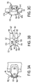
- FIG. 1A illustrates a plan view of a first surface of a slide fastener according to one embodiment of the invention.
- FIG. 1B illustrates a plan view of a second surface of the slide fastener shown in FIG. 1A .
- FIG. 2A illustrates a perspective view of the first surface of the slide fastener shown in FIG. 1A .
- FIG. 2B illustrates a perspective view of the second surface of the slide fastener shown in FIG. 1A .
- FIG. 3A illustrates a partial plan view of a coupling element molded to the first surface of the slide fastener shown in FIG. 1A .
- FIG. 3B illustrates a side view of the coupling element shown in FIG. 3A .
- FIG. 3C illustrates an end view of the coupling element shown in FIG. 3A .
- FIG. 4A illustrates a plan view of a first surface of a slide fastener according to another embodiment of the invention.
- FIG. 4B illustrates a plan view of a second surface of the slide fastener shown in FIG. 4A .
- FIG. 5A illustrates a perspective view of the first surface of the slide fastener shown in FIG. 4A .
- FIG. 5B illustrates a perspective view of the second surface of the slide fastener shown in FIG. 4A .
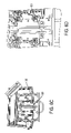
- FIGS. 6A-6D illustrate exemplary test equipment for testing the water repellency of the slide fasteners shown in FIGS. 1A-5B .
- FIGS. 1A , 1 B, 2 A, and 2 B A slide fastener according to various embodiments is shown in FIGS. 1A , 1 B, 2 A, and 2 B.
- the slide fastener 100 includes a first set of coupling elements 105 disposed on a first stringer tape 101 and a second set of coupling elements 105 disposed on a second stringer tape 103 .
- the stringer tapes 101 , 103 each include a first surface 109 and a second surface 111 that are opposite each other.
- Each coupling element 105 includes a first base portion 135 , a second base portion 125 , an engaging portion 137 , and a front face 121 .
- the first base portion 135 is disposed adjacent the first surface 109 of the stringer tape 101 , 103
- the second base portion 125 is disposed adjacent the second surface 111 of the stringer tape 101 , 103 .
- the first base portion 135 and the second base portion 125 define a channel 151 therebetween for receiving a longitudinal edge 107 of the stringer tape 101 , 103 .
- the engaging portion 137 extends outwardly from the first 135 and the second base portions 125 and includes a first surface 113 and a second surface 115 .
- the first surface 113 of the engaging portion 137 is spaced apart from and cofaces the second surface 115 of the engaging portion 137 .
- the first surface 113 of the engaging portion 137 has a first shape and is disposed adjacent the first surface 109 of the stringer tape 101 , 103
- the second surface 115 of the engaging portion 137 has a second shape and is disposed adjacent the second surface 111 of the stringer tape 101 , 103 .
- a portion of the second surface 115 of the engaging portion 137 adjacent a distal end 153 of the engaging portion 137 has a width dimension W 1 that is greater than a width dimension W 2 of a portion of the first surface 113 of the engaging portion 137 adjacent the distal end 153 .
- the width dimensions are measured in a width plane that is substantially parallel to the first surface 113 and the second surface 115 of the engaging portion 137 .
- the first shape of the first surface 113 is substantially triangular as viewed from the first surface 109 of the stringer tape 101 , 103
- the second shape of the second surface 115 is substantially gear shaped as viewed from the second surface 111 of the stringer tape 101 , 103 .
- the first shape of the first surface 213 of the engaging portion 237 is substantially trapezoidal as viewed from the first surface 209 of the stringer tape 201 , 203 .
- coupling elements 205 having substantially trapezoidal shaped first surfaces 213 may provide better water repellency than coupling elements 105 having substantially triangular first surfaces 213 .
- coupling elements 105 having substantially triangular first surfaces 115 may provide more flexibility in the plane containing the stringer tapes 101 , 103 than coupling elements 205 having substantially trapezoidal first surfaces 213 , according to one embodiment.
- the engaging portion 137 includes a sealing portion 139 and a fastening portion 145 , and the sealing portion 139 and the fastening portion 145 abut each other at an interface 141 .
- the sealing portion 139 extends between the first surface 113 and the interface 141
- the fastening portion 145 extends between the second surface 115 and the interface 141 .
- the interface 141 lies in a plane that is substantially parallel to the first surface 113 and the second surface 115 .
- the sealing portion 139 includes a first engaging face 144 a and a second engaging face 144 b.
- the first and second engaging faces 144 a, 144 b extend from the first surface 113 to the interface 141 .
- the fastening portion 145 includes a neck portion 127 and a head portion 129 .
- the head portion 129 includes the front face 121
- the neck portion 127 is disposed between the second base portion 125 and the head portion 129 .
- the neck portion 127 has a width dimension that is less than the width dimension of the head portion 129 and the second base portion 125 .
- At least a portion 143 of the head portion 129 is wider in the width plane than the distal end 153 of the first surface 113 such that the portion 143 of the head portion 129 is visible when viewing the slide fastener 100 from the first side 109 of the stringer tapes 101 , 103 .
- a first fastening face 147 a and a second fastening face 147 b extend from the second surface 115 to the interface 141 .
- the front face 121 is disposed at the distal end 153 of the engaging portion 137 and extends between the first 113 and the second surface 115 thereof.
- a first gap 155 is defined by the first surfaces 113 and the engaging faces 144 a, 144 b of two adjacent coupling elements 105 in the second set
- a second gap 157 is defined by the second surfaces 115 and the fastening faces 147 a, 147 b of the two adjacent coupling elements 105 in the second set
- a third gap 159 is defined by the first surfaces 113 and the engaging faces 144 a, 144 b of two adjacent coupling elements 105 in the first set
- a fourth gap 161 is defined by the second surfaces 115 and the fastening faces 147 a, 147 b of the two adjacent coupling elements 105 in the first set.
- the first surface 113 of the engaging portion 137 and the sealing portion 139 of a first coupling element 105 a in the first set are at least partially disposed within the first gap 155
- the second surface 115 of the engaging portion 137 and the fastening portion 145 of the first coupling element 105 a are at least partially disposed within the second gap 157 .
- first surface 113 of the engaging portion 137 and the sealing portion 139 of a second coupling element 105 b in the second set are at least partially disposed within the third gap 159
- second surface 115 of the engaging portion 137 and the fastening portion 145 of the second coupling element 105 b are at least partially disposed within the fourth gap 161 .
- the head portions 129 of the coupling elements 105 in the first set are disposed between adjacent neck portions 127 of the coupling elements 105 in the second set
- the head portions 129 of the coupling elements 105 in the second set are disposed between adjacent neck portions 127 of the coupling elements 105 in the first set. The engagement of the head portions 129 between the neck portions 127 prevents the coupling elements 105 from inadvertently disengaging.
- the front face 121 of the first coupling element 105 a is disposed adjacent and cofaces the longitudinal edge 107 of the second stringer tape 103
- the front face 121 of the second coupling element 105 b is disposed adjacent and cofaces the longitudinal edge 107 of the first stringer tape 101 .
- the engaging portions 137 of adjacent coupling elements 105 on the first stringer tape 101 are spaced apart from each other such that a portion 117 of the longitudinal edge 107 of the first stringer tape 101 is exposed between the adjacent coupling elements 105 .
- the engaging portions 137 of adjacent coupling elements 105 on the second stringer tape 103 are spaced apart from each other such that a portion 117 of the longitudinal edge 107 of the second stringer tape 103 is exposed between the adjacent coupling elements 105 .
- first base portions 135 of the adjacent coupling elements 105 on the first coupling tape 101 may be spaced apart, and the second base portions 125 of the adjacent coupling elements 105 on the first coupling tape 101 may be spaced apart, as shown in the embodiment in FIGS. 1A-3C .
- first base portions 135 of the adjacent coupling elements 105 on the second coupling tape 103 may be spaced apart, and the second base portions 125 of the adjacent coupling elements 105 on the second coupling tape 103 may be spaced apart.
- the first 135 and second base portions 125 on each stringer tape 101 , 103 may be formed continuously.
- the front face 121 defines a channel 123 that is spaced apart from the channel 151 and is substantially parallel with the longitudinal edge 107 .
- the channel 123 is configured for receiving the portion 117 of the longitudinal edge 107 of the opposite stringer tape 101 , 103 when the coupling elements 105 on the stringer tapes 101 , 103 are joined together.
- each coupling element 105 is molded from a plastic material, such as polyester, polypropylene, polyethylene, or polyamide.
- the coupling elements may be formed of other materials, including, for example, metal, ceramic, or wood, or a combination thereof.
- the coupling elements 105 in the first set are molded to the first stringer tape 101
- the coupling elements 105 in the second set are molded to the second stringer tape 103 .
- the coupling elements 105 are molded to the stringer tapes 101 , 103 using an injection molding process.
- the coupling elements may be formed separately and attached to the stringer tapes.
- the first surface 109 of each stringer tape 101 , 103 is laminated with a liquid resistant coating.
- the liquid resistant coating may include, for example, polyurethane, polyester, polypropylene, nylon, poly vinyl chloride, or another type of film.
- the first surface 109 of each stringer tape 101 , 103 is laminated prior to molding the coupling elements 105 onto the stringer tapes 101 , 103 , according to a particular embodiment.
- the lamination step may occur after the coupling elements 105 are molded to the stringer tapes 101 , 103 .
- the stringer tapes 101 , 103 are attached to an article having two seams to be joined together (e.g., clothing or bag) such that first surfaces 109 of stringer tapes 101 , 103 and the first surfaces 113 of the coupling elements 105 are disposed adjacent an outside of the article and the second surfaces 111 of the stringer tapes 101 , 103 and the second surfaces 115 of the coupling elements 105 are disposed adjacent an inside of the article.
- a zipper 119 is urged over the coupling elements 105 in a first direction to join the coupling elements 105 on each stringer tape 101 , 103 into engagement with each other, and the zipper 119 is urged in a second direction opposite the first direction to disengage the coupling elements 105 on each stringer tape 101 , 103 .
- FIGS. 1A-5B are substantially water resistant.
- liquids e.g., water
- the coupling elements 105 , 205 are engaged, liquids (e.g., water) are substantially prevented from leaking from the first surface 109 , 209 of each stringer tape 101 , 103 , 201 , 203 and the first surface 113 , 213 of each coupling element 105 , 205 to the second surface 111 , 213 of each stringer tape 101 , 103 , 201 , 203 and the second surface 115 , 215 of each coupling element 105 , 205 .
- the liquid resistant coating on the first surfaces 109 , 209 of the stringer tapes 101 , 103 , 201 , 203 substantially prevents liquids, such as water, from penetrating through the stringer tapes 101 , 103 , 201 , 203 .
- Liquids are also prevented from penetrating between adjacent coupling elements 105 , 205 disposed on opposite stringer tapes 101 , 103 , 201 , 203 by the engagement of the engaging faces 144 a, 144 b, 244 a, 244 b of the sealing portions 139 , 239 of the coupling elements 105 , 205 .
- liquid that may penetrate between adjacent engaging faces 144 a, 144 b, 244 a, 244 b of the coupling elements 105 , 205 is prevented from moving to the second surfaces 111 , 211 of the stringer tapes 101 , 103 , 201 , 203 and the second surfaces of the 115 , 215 of the coupling elements 105 , 205 by the portion 143 , 243 of the head portion 129 , 229 adjacent the interface 141 , 241 between the sealing portion 139 , 239 and the fastening portion 145 , 245 .
- liquids are substantially prevented from penetrating through the interface between the front face 121 , 221 of each coupling element 105 , 205 and the longitudinal edge 107 , 207 of the opposite stringer tape 101 , 103 , 201 , 203 by the engagement of the channel 123 , 223 with the portion 117 , 217 of the longitudinal edge 107 , 207 between adjacent engaging portions 137 , 237 .
- the embodiment of the slide fasteners 100 , 200 shown in FIGS. 1A-5B were subjected to a water repellency test, and both embodiments 100 , 200 prevented less than 0.5 cubic centimeters (cc) of water per fifteen minutes from passing through the slide fasteners 100 , 200 .
- the water repellency test included securing the slide fastener 100 , 200 to an opening 301 in a box 300 such that the first surface 109 , 209 of each stringer tape 101 , 103 , 201 , 203 faced the outside of the box 300 and the second surface 111 , 211 of each stringer tape 101 , 103 , 201 , 203 faced the inside of the box 300 .
- the opening 301 was defined in a side face 303 of the box 300 , and the side face 303 of the box 300 was disposed at an angle to a top surface of the box 300 .
- a water source 320 such as a shower, was positioned adjacent the box 300 such that the water flowing from the water source 320 approached the side face 303 at substantially 45°.
- the water source 320 released water at a rate of approximately 100 mm/hour.
- the water inside the box 300 was measured to determine the ability of the slide fastener 100 , 200 to repel water. As noted above, less than 0.5 cc of water passed through the slide fasteners 100 , 200 during the test.
Landscapes
- Slide Fasteners (AREA)
- Casting Support Devices, Ladles, And Melt Control Thereby (AREA)
- Two-Way Televisions, Distribution Of Moving Picture Or The Like (AREA)
- Absorbent Articles And Supports Therefor (AREA)
Abstract
Description
- Typically, water resistant slide fasteners include coil coupling elements that are attached to stringer tapes. However, zippers used with the coil coupling elements tend to stick and become difficult to operate at lower temperatures, making them unsuitable for use with outdoor clothing that may be worn in low temperature environments. In addition, these zippers become difficult to operate when exposed to sand, debris, or ice.
- Plastic molded coupling elements are not as susceptible to sticking at lower temperatures or when exposed to sand, debris, or ice, but known plastic molded coupling elements do not repel water effectively.
- Accordingly, there is a need in the art for an improved slide fastener that is water resistant.
- Various embodiments of the invention provide a plurality of coupling elements for use with a slide fastener. Each of the coupling elements includes a first base portion, a second base portion, an engaging portion, and a front face. The first base portion is disposed adjacent a first surface of a stringer tape, and the second base portion is disposed adjacent a second surface of the stringer tape, wherein the first surface of the stringer tape is opposite the second surface of the stringer tape. In addition, the first base portion and the second base portion define a channel therebetween for receiving a longitudinal edge of the stringer tape.
- The engaging portion extends outwardly from the first and the second base portions, and the engaging portion includes a first surface and a second surface. The first surface of the engaging portion is spaced apart from and cofaces the second surface of the engaging portion. The first surface of the engaging portion has a first shape, and the second surface of the engaging portion has a second shape. A portion of the second shape adjacent a distal end of the engaging portion has a width dimension that is greater than a width dimension of a portion of the first shape adjacent the distal end. Each of the width dimensions are measured in a width plane that is substantially parallel to the first surface and the second surface of the engaging portion.
- The front face is disposed at the distal end of the engaging portion and extends between the first and the second surface thereof.
- A first set of coupling elements are disposed on a first stringer tape, and a second set of coupling elements are disposed on a second stringer tape. A first gap is defined by the first surfaces of the engaging portions of two adjacent coupling elements in the second set, and a second gap is defined by the second surfaces of the engaging portions of the two adjacent coupling elements in the second set. In addition, a third gap is defined by the first surfaces of the engaging portions of two adjacent coupling elements in the first set, and a fourth gap is defined by the second surfaces of the engaging portions of the two adjacent coupling elements in the first set.
- When the first set of coupling elements are removably joined together with the second set of coupling elements, the first surface of the engaging portion of a first coupling element in the first set is at least partially disposed within the first gap, and the second surface of the engaging portion of the first coupling element is at least partially disposed within the second gap. In addition, the first surface of the engaging portion of a second coupling element in the second set is at least partially disposed within the third gap, and the second surface of the engaging portion of the second coupling element is at least partially disposed within the fourth gap. Furthermore, the front face of the first coupling element is disposed adjacent and cofaces the longitudinal edge of the second stringer tape, and the front face of the second coupling element is disposed adjacent and cofaces the longitudinal edge of the first stringer tape.
- Various embodiments of a slide fastener may include coupling elements such as those described above. In a particular embodiment, the first surfaces of the first and the second stringer tapes are laminated with a liquid resistant material. In addition, in one embodiment, the coupling elements are molded from a plastic material.
- Furthermore, in one embodiment, the channel described above is a first channel, and the front face defines a second channel. When the first set of coupling elements are removably joined together with the second set of coupling elements, the second channel of the first coupling element receives a portion of the longitudinal edge of the second stringer tape between the two adjacent coupling elements in the second set, and the second channel of the second coupling element receives a portion of the longitudinal edge of the first stringer tape between the two adjacent coupling elements in the first set.
- According to various embodiments, the width of the first shape decreases from the first base portion to the front face, and the second shape comprises a neck portion and a head portion. The head portion is adjacent the distal end of the engaging portion and the neck portion is disposed between the second base portion and the head portion. A width of the neck portion is less than a width of the head portion. When the first set of coupling elements are removably joined together with the second set of coupling elements, the head portion of the first coupling element is disposed between the neck portions of the two adjacent coupling elements in the second set, and the head portion of the second coupling element is disposed between the neck portions of the two adjacent coupling elements in the first set. In one embodiment, the first shape is substantially triangular, and in another embodiment, the first shape is substantially trapezoidal.
- Having thus described various embodiments of the invention in general terms, reference will now be made to the accompanying drawings, which are not necessarily drawn to scale, and wherein:
-
FIG. 1A illustrates a plan view of a first surface of a slide fastener according to one embodiment of the invention. -
FIG. 1B illustrates a plan view of a second surface of the slide fastener shown inFIG. 1A . -
FIG. 2A illustrates a perspective view of the first surface of the slide fastener shown inFIG. 1A . -
FIG. 2B illustrates a perspective view of the second surface of the slide fastener shown inFIG. 1A . -
FIG. 3A illustrates a partial plan view of a coupling element molded to the first surface of the slide fastener shown inFIG. 1A . -
FIG. 3B illustrates a side view of the coupling element shown inFIG. 3A . -
FIG. 3C illustrates an end view of the coupling element shown inFIG. 3A . -
FIG. 4A illustrates a plan view of a first surface of a slide fastener according to another embodiment of the invention. -
FIG. 4B illustrates a plan view of a second surface of the slide fastener shown inFIG. 4A . -
FIG. 5A illustrates a perspective view of the first surface of the slide fastener shown inFIG. 4A . -
FIG. 5B illustrates a perspective view of the second surface of the slide fastener shown inFIG. 4A . -
FIGS. 6A-6D illustrate exemplary test equipment for testing the water repellency of the slide fasteners shown inFIGS. 1A-5B . - Various embodiments of the invention are described more fully hereinafter with reference to the accompanying drawings, in which some, but not all embodiments of the invention are shown in the figures. These inventions may be embodied in many different forms and should not be construed as limited to the embodiments set forth herein. Rather, these embodiments are provided so that this disclosure will satisfy applicable legal requirements.
- A slide fastener according to various embodiments is shown in
FIGS. 1A , 1B, 2A, and 2B. Theslide fastener 100 includes a first set ofcoupling elements 105 disposed on afirst stringer tape 101 and a second set ofcoupling elements 105 disposed on asecond stringer tape 103. Thestringer tapes first surface 109 and asecond surface 111 that are opposite each other. - Each
coupling element 105 includes afirst base portion 135, asecond base portion 125, an engagingportion 137, and afront face 121. Thefirst base portion 135 is disposed adjacent thefirst surface 109 of thestringer tape second base portion 125 is disposed adjacent thesecond surface 111 of thestringer tape first base portion 135 and thesecond base portion 125 define achannel 151 therebetween for receiving alongitudinal edge 107 of thestringer tape - The engaging
portion 137 extends outwardly from the first 135 and thesecond base portions 125 and includes afirst surface 113 and asecond surface 115. Thefirst surface 113 of the engagingportion 137 is spaced apart from and cofaces thesecond surface 115 of the engagingportion 137. Thefirst surface 113 of the engagingportion 137 has a first shape and is disposed adjacent thefirst surface 109 of thestringer tape second surface 115 of the engagingportion 137 has a second shape and is disposed adjacent thesecond surface 111 of thestringer tape second surface 115 of the engagingportion 137 adjacent adistal end 153 of the engagingportion 137 has a width dimension W1 that is greater than a width dimension W2 of a portion of thefirst surface 113 of the engagingportion 137 adjacent thedistal end 153. The width dimensions are measured in a width plane that is substantially parallel to thefirst surface 113 and thesecond surface 115 of the engagingportion 137. In the embodiment shown inFIGS. 1A-3C , the first shape of thefirst surface 113 is substantially triangular as viewed from thefirst surface 109 of thestringer tape second surface 115 is substantially gear shaped as viewed from thesecond surface 111 of thestringer tape - In an alternative embodiment shown in
FIGS. 4A-5B , the first shape of thefirst surface 213 of the engaging portion 237 is substantially trapezoidal as viewed from thefirst surface 209 of thestringer tape coupling elements 205 having substantially trapezoidal shaped first surfaces 213 may provide better water repellency than couplingelements 105 having substantially triangular first surfaces 213. However,coupling elements 105 having substantially triangularfirst surfaces 115 may provide more flexibility in the plane containing thestringer tapes elements 205 having substantially trapezoidalfirst surfaces 213, according to one embodiment. - In the embodiment shown in
FIGS. 1A-3C , the engagingportion 137 includes a sealingportion 139 and afastening portion 145, and the sealingportion 139 and thefastening portion 145 abut each other at aninterface 141. In particular, the sealingportion 139 extends between thefirst surface 113 and theinterface 141, and thefastening portion 145 extends between thesecond surface 115 and theinterface 141. In one embodiment, theinterface 141 lies in a plane that is substantially parallel to thefirst surface 113 and thesecond surface 115. - As shown in FIGS. 1A and 3B-3C, the sealing
portion 139 includes a firstengaging face 144 a and a secondengaging face 144 b. The first and second engaging faces 144 a, 144 b extend from thefirst surface 113 to theinterface 141. - According to the embodiment shown in FIGS. 1B and 3B-3C, the
fastening portion 145 includes aneck portion 127 and ahead portion 129. Thehead portion 129 includes thefront face 121, and theneck portion 127 is disposed between thesecond base portion 125 and thehead portion 129. Theneck portion 127 has a width dimension that is less than the width dimension of thehead portion 129 and thesecond base portion 125. According to the embodiment shown inFIGS. 1A-3C , at least aportion 143 of thehead portion 129 is wider in the width plane than thedistal end 153 of thefirst surface 113 such that theportion 143 of thehead portion 129 is visible when viewing theslide fastener 100 from thefirst side 109 of thestringer tapes first fastening face 147 a and asecond fastening face 147 b extend from thesecond surface 115 to theinterface 141. Furthermore, thefront face 121 is disposed at thedistal end 153 of the engagingportion 137 and extends between the first 113 and thesecond surface 115 thereof. - A
first gap 155 is defined by thefirst surfaces 113 and the engaging faces 144 a, 144 b of twoadjacent coupling elements 105 in the second set, and asecond gap 157 is defined by thesecond surfaces 115 and the fastening faces 147 a, 147 b of the twoadjacent coupling elements 105 in the second set. In addition, athird gap 159 is defined by thefirst surfaces 113 and the engaging faces 144 a, 144 b of twoadjacent coupling elements 105 in the first set, and afourth gap 161 is defined by thesecond surfaces 115 and the fastening faces 147 a, 147 b of the twoadjacent coupling elements 105 in the first set. - When the first set of
coupling elements 105 are removably joined together with the second set ofcoupling elements 105, thefirst surface 113 of the engagingportion 137 and the sealingportion 139 of afirst coupling element 105 a in the first set are at least partially disposed within thefirst gap 155, and thesecond surface 115 of the engagingportion 137 and thefastening portion 145 of thefirst coupling element 105 a are at least partially disposed within thesecond gap 157. In addition, thefirst surface 113 of the engagingportion 137 and the sealingportion 139 of asecond coupling element 105 b in the second set are at least partially disposed within thethird gap 159, and thesecond surface 115 of the engagingportion 137 and thefastening portion 145 of thesecond coupling element 105 b are at least partially disposed within thefourth gap 161. In particular, thehead portions 129 of thecoupling elements 105 in the first set are disposed betweenadjacent neck portions 127 of thecoupling elements 105 in the second set, and thehead portions 129 of thecoupling elements 105 in the second set are disposed betweenadjacent neck portions 127 of thecoupling elements 105 in the first set. The engagement of thehead portions 129 between theneck portions 127 prevents thecoupling elements 105 from inadvertently disengaging. - Furthermore, when the first set of
coupling elements 105 are removably joined together with the second set ofcoupling elements 105, thefront face 121 of thefirst coupling element 105 a is disposed adjacent and cofaces thelongitudinal edge 107 of thesecond stringer tape 103, and thefront face 121 of thesecond coupling element 105 b is disposed adjacent and cofaces thelongitudinal edge 107 of thefirst stringer tape 101. - In a particular embodiment, such as shown in
FIGS. 1A-3C , the engagingportions 137 ofadjacent coupling elements 105 on thefirst stringer tape 101 are spaced apart from each other such that aportion 117 of thelongitudinal edge 107 of thefirst stringer tape 101 is exposed between theadjacent coupling elements 105. Similarly, the engagingportions 137 ofadjacent coupling elements 105 on thesecond stringer tape 103 are spaced apart from each other such that aportion 117 of thelongitudinal edge 107 of thesecond stringer tape 103 is exposed between theadjacent coupling elements 105. - In addition, the
first base portions 135 of theadjacent coupling elements 105 on thefirst coupling tape 101 may be spaced apart, and thesecond base portions 125 of theadjacent coupling elements 105 on thefirst coupling tape 101 may be spaced apart, as shown in the embodiment inFIGS. 1A-3C . Similarly, thefirst base portions 135 of theadjacent coupling elements 105 on thesecond coupling tape 103 may be spaced apart, and thesecond base portions 125 of theadjacent coupling elements 105 on thesecond coupling tape 103 may be spaced apart. However, in an alternative embodiment (not shown), the first 135 andsecond base portions 125 on eachstringer tape - In addition, in the embodiment shown in
FIGS. 3A and 3B , thefront face 121 defines achannel 123 that is spaced apart from thechannel 151 and is substantially parallel with thelongitudinal edge 107. Thechannel 123 is configured for receiving theportion 117 of thelongitudinal edge 107 of theopposite stringer tape coupling elements 105 on thestringer tapes - According to various embodiments, each
coupling element 105 is molded from a plastic material, such as polyester, polypropylene, polyethylene, or polyamide. However, in various other embodiments, the coupling elements may be formed of other materials, including, for example, metal, ceramic, or wood, or a combination thereof. - In addition, in one embodiment, the
coupling elements 105 in the first set are molded to thefirst stringer tape 101, and thecoupling elements 105 in the second set are molded to thesecond stringer tape 103. For example, in one embodiment, thecoupling elements 105 are molded to thestringer tapes - According to a particular embodiment, the
first surface 109 of eachstringer tape first surface 109 of eachstringer tape coupling elements 105 onto thestringer tapes coupling elements 105 are molded to thestringer tapes - The
stringer tapes first surfaces 109 ofstringer tapes first surfaces 113 of thecoupling elements 105 are disposed adjacent an outside of the article and thesecond surfaces 111 of thestringer tapes second surfaces 115 of thecoupling elements 105 are disposed adjacent an inside of the article. Azipper 119 is urged over thecoupling elements 105 in a first direction to join thecoupling elements 105 on eachstringer tape zipper 119 is urged in a second direction opposite the first direction to disengage thecoupling elements 105 on eachstringer tape - The embodiments shown in
FIGS. 1A-5B are substantially water resistant. In particular, when thecoupling elements first surface stringer tape first surface coupling element second surface stringer tape second surface coupling element FIGS. 1A-5B , the liquid resistant coating on thefirst surfaces stringer tapes stringer tapes adjacent coupling elements opposite stringer tapes portions coupling elements engaging faces coupling elements second surfaces stringer tapes coupling elements portion head portion interface 141, 241 between the sealingportion fastening portion front face coupling element longitudinal edge opposite stringer tape channel portion longitudinal edge portions 137, 237. - The embodiment of the
slide fasteners 100, 200 shown inFIGS. 1A-5B were subjected to a water repellency test, and bothembodiments 100, 200 prevented less than 0.5 cubic centimeters (cc) of water per fifteen minutes from passing through theslide fasteners 100, 200. In particular, as shown inFIGS. 6A-6D , the water repellency test included securing theslide fastener 100, 200 to anopening 301 in abox 300 such that thefirst surface stringer tape box 300 and thesecond surface stringer tape box 300. Theopening 301 was defined in aside face 303 of thebox 300, and theside face 303 of thebox 300 was disposed at an angle to a top surface of thebox 300. Awater source 320, such as a shower, was positioned adjacent thebox 300 such that the water flowing from thewater source 320 approached theside face 303 at substantially 45°. Thewater source 320 released water at a rate of approximately 100 mm/hour. After approximately fifteen minutes, the water inside thebox 300 was measured to determine the ability of theslide fastener 100, 200 to repel water. As noted above, less than 0.5 cc of water passed through theslide fasteners 100, 200 during the test. - Although this invention has been described in specific detail with reference to the disclosed embodiments, it will be understood that many variations and modifications may be effected within the spirit and scope of the invention as described in the appended claims.
Claims (22)
Priority Applications (12)
| Application Number | Priority Date | Filing Date | Title |
|---|---|---|---|
| US12/164,659 US8695178B2 (en) | 2008-06-30 | 2008-06-30 | Slide fastener |
| JP2009135528A JP5207142B2 (en) | 2008-06-30 | 2009-05-15 | Slide fastener |
| TW098116732A TWI350738B (en) | 2008-06-30 | 2009-05-20 | Slide fastener |
| US12/477,773 US8359717B2 (en) | 2008-06-30 | 2009-06-03 | Slide fastener |
| EP09251549A EP2140776B1 (en) | 2008-06-30 | 2009-06-12 | Slide fastener |
| ES09251549T ES2360847T3 (en) | 2008-06-30 | 2009-06-12 | ZIP CLOSURE. |
| AT09251549T ATE502534T1 (en) | 2008-06-30 | 2009-06-12 | Zipper |
| DE602009000945T DE602009000945D1 (en) | 2008-06-30 | 2009-06-12 | zipper |
| KR1020090058123A KR101096968B1 (en) | 2008-06-30 | 2009-06-29 | Slide fasteners |
| BRPI0902092-6A BRPI0902092B1 (en) | 2008-06-30 | 2009-06-29 | SLIDING CLOSURE |
| CN2009101484788A CN101617876B (en) | 2008-06-30 | 2009-06-30 | zipper |
| HK10105223.6A HK1137306B (en) | 2008-06-30 | 2010-05-28 | Slide fastener |
Applications Claiming Priority (1)
| Application Number | Priority Date | Filing Date | Title |
|---|---|---|---|
| US12/164,659 US8695178B2 (en) | 2008-06-30 | 2008-06-30 | Slide fastener |
Related Child Applications (1)
| Application Number | Title | Priority Date | Filing Date |
|---|---|---|---|
| US12/477,773 Continuation-In-Part US8359717B2 (en) | 2008-06-30 | 2009-06-03 | Slide fastener |
Publications (2)
| Publication Number | Publication Date |
|---|---|
| US20090320249A1 true US20090320249A1 (en) | 2009-12-31 |
| US8695178B2 US8695178B2 (en) | 2014-04-15 |
Family
ID=41171343
Family Applications (2)
| Application Number | Title | Priority Date | Filing Date |
|---|---|---|---|
| US12/164,659 Active 2032-01-15 US8695178B2 (en) | 2008-06-30 | 2008-06-30 | Slide fastener |
| US12/477,773 Active 2030-03-15 US8359717B2 (en) | 2008-06-30 | 2009-06-03 | Slide fastener |
Family Applications After (1)
| Application Number | Title | Priority Date | Filing Date |
|---|---|---|---|
| US12/477,773 Active 2030-03-15 US8359717B2 (en) | 2008-06-30 | 2009-06-03 | Slide fastener |
Country Status (10)
| Country | Link |
|---|---|
| US (2) | US8695178B2 (en) |
| EP (1) | EP2140776B1 (en) |
| JP (1) | JP5207142B2 (en) |
| KR (1) | KR101096968B1 (en) |
| CN (1) | CN101617876B (en) |
| AT (1) | ATE502534T1 (en) |
| BR (1) | BRPI0902092B1 (en) |
| DE (1) | DE602009000945D1 (en) |
| ES (1) | ES2360847T3 (en) |
| TW (1) | TWI350738B (en) |
Cited By (4)
| Publication number | Priority date | Publication date | Assignee | Title |
|---|---|---|---|---|
| CN103027447A (en) * | 2011-10-07 | 2013-04-10 | Ykk株式会社 | Zipper chain belt |
| US9179744B2 (en) | 2010-10-29 | 2015-11-10 | Ykk Corporation | Fastener and article provided with fastener |
| CN110678099A (en) * | 2019-08-22 | 2020-01-10 | 深圳市华圣达拉链有限公司 | Zipper tooth and zipper |
| DE112010005885B4 (en) * | 2010-09-17 | 2021-06-24 | Ykk Corporation | Zipper and method of making the zipper |
Families Citing this family (29)
| Publication number | Priority date | Publication date | Assignee | Title |
|---|---|---|---|---|
| EP2674055A3 (en) * | 2009-01-13 | 2015-07-08 | YKK Corporation | Slide fastener |
| CN104585980B (en) * | 2009-11-30 | 2017-06-06 | Ykk株式会社 | Liquid-tight slide fastener |
| WO2012020499A1 (en) * | 2010-08-12 | 2012-02-16 | Ykk株式会社 | Slide fastener |
| US8484764B2 (en) | 2010-08-18 | 2013-07-16 | Under Armour, Inc. | Zipper arrangement |
| US8341809B2 (en) | 2010-11-16 | 2013-01-01 | Under Armour, Inc. | Zipper arrangement with funnel grip |
| US8484811B2 (en) | 2010-11-16 | 2013-07-16 | Under Armour, Inc. | Zipper arrangement with wheeled slider |
| US8528115B2 (en) | 2010-11-16 | 2013-09-10 | Under Armour, Inc. | Zipper arrangement with foldable pull |
| KR101558070B1 (en) * | 2011-03-24 | 2015-10-06 | 와이케이케이 가부시끼가이샤 | Slide fastener and slider with simple locking mechanism |
| CN103169205B (en) * | 2012-06-27 | 2016-01-20 | 福建浔兴拉链科技股份有限公司 | A kind of zipper tooth and adopt the slide fastener of this zipper tooth |
| DE112012006591B4 (en) | 2012-06-28 | 2019-08-14 | Ykk Corp. | Waterproof zipper |
| CN102726893B (en) * | 2012-07-22 | 2014-07-16 | 张卫 | Dual-purpose zipper |
| WO2015033383A1 (en) * | 2013-09-03 | 2015-03-12 | Ykk株式会社 | Slide fastener chain, slide fastener, and manufacturing method for slide fastener chain |
| USD732425S1 (en) * | 2013-11-13 | 2015-06-23 | Wang Lap Ronny Ng | Slide fastener |
| USD724996S1 (en) * | 2014-04-04 | 2015-03-24 | Able Investments Limited | Zipper |
| USD726589S1 (en) * | 2014-04-30 | 2015-04-14 | Lee Tak Fung (Hong Kong) Co., Ltd. | Slide fastener |
| US10575601B2 (en) | 2015-10-02 | 2020-03-03 | Under Armour, Inc. | Stop for zipper arrangement |
| CN105167340B (en) * | 2015-10-14 | 2021-05-04 | 泉州迪特工业产品设计有限公司 | A metal wire and a zipper using the same |
| JP6789632B2 (en) * | 2016-01-15 | 2020-11-25 | Ykk株式会社 | Ceramic parts, fastener stringers containing them, and methods for manufacturing fastener stringers. |
| USD818394S1 (en) * | 2016-06-30 | 2018-05-22 | Ideal Fastener (Guangdong) Industries Ltd. | Zipper tooth |
| TWI581732B (en) * | 2016-07-20 | 2017-05-11 | 冠宇拉鍊股份有限公司 | Double-layered watertight zipper |
| CN106418918B (en) * | 2016-08-29 | 2020-02-04 | 福建浔兴拉链科技股份有限公司 | Material-saving chain tooth |
| USD809426S1 (en) * | 2016-09-14 | 2018-02-06 | Eric Gates | Link chain zipper |
| USD828783S1 (en) * | 2017-05-05 | 2018-09-18 | Ideal Fastener (Guangdong) Industries Ltd. | Zip teeth |
| CN109294044A (en) * | 2018-08-07 | 2019-02-01 | 道晟拉链科技(太仓)有限公司 | A kind of antistatic slide fastener coupling element and preparation method thereof |
| JP7190573B2 (en) * | 2019-07-04 | 2022-12-15 | Ykk株式会社 | Products with element members and slide fasteners |
| JP2023503233A (en) | 2019-11-23 | 2023-01-27 | タロン テクノロジーズ、インコーポレイティッド | curved zipper |
| US11363860B2 (en) | 2019-11-23 | 2022-06-21 | Talon Technologies, Inc. | Waterproof curved zippers |
| USD979886S1 (en) * | 2020-09-10 | 2023-03-07 | Ideal Fastener (Guangdong) Industries Ltd. | Zipper tooth |
| WO2023245465A1 (en) * | 2022-06-22 | 2023-12-28 | 浙江华圣达拉链科技有限公司 | Zipper |
Citations (16)
| Publication number | Priority date | Publication date | Assignee | Title |
|---|---|---|---|---|
| US2157828A (en) * | 1937-06-12 | 1939-05-09 | Kuna Josef | Sliding clasp fastener |
| US2371591A (en) * | 1943-10-23 | 1945-03-13 | Waldes Kohinoor Inc | Slide fastener |
| US2798275A (en) * | 1954-02-26 | 1957-07-09 | Louis H Morin | Center ledge scoop for separable fasteners |
| US3874038A (en) * | 1972-08-03 | 1975-04-01 | Yoshida Kogyo Kk | Sliding clasp coupling elements |
| US4502190A (en) * | 1982-05-19 | 1985-03-05 | Yoshida Kogyo K. K. | Slide fastener stringer |
| US4513483A (en) * | 1982-12-13 | 1985-04-30 | Yoshida Kogyo K. K. | Slide fastener stringer |
| US4520535A (en) * | 1982-05-07 | 1985-06-04 | Yoshida Kogyo K. K. | Slide fastener having discrete coupling elements |
| US4765038A (en) * | 1982-09-09 | 1988-08-23 | Yoshida Kogyo K. K. | Watertight slide fastener stringer |
| US6105214A (en) * | 1998-09-25 | 2000-08-22 | Press; Stuart | Water resistant slide fastener and process for preparing same |
| US20040187277A1 (en) * | 2003-03-31 | 2004-09-30 | Ykk Europe Limited | Fastener |
| US20060207069A1 (en) * | 2005-03-17 | 2006-09-21 | Unitech Zipper And Machinery Co., Ltd. | Water resistant slide fastener |
| US20060260104A1 (en) * | 2005-05-20 | 2006-11-23 | Naoyuki Himi | Slide fastener chain |
| US7337508B2 (en) * | 2004-07-02 | 2008-03-04 | Ykk Corporation | Zip fastener with emergency opening facility |
| USD628123S1 (en) * | 2009-03-25 | 2010-11-30 | Ykk Corporation | Chain for slide fastener |
| USD632218S1 (en) * | 2009-11-17 | 2011-02-08 | Ykk Corporation | Slide fastener element |
| USD657287S1 (en) * | 2011-06-28 | 2012-04-10 | Unitech Zipper & Machinery Co., Ltd. | Zipper tooth |
Family Cites Families (7)
| Publication number | Priority date | Publication date | Assignee | Title |
|---|---|---|---|---|
| JPS4533956Y1 (en) * | 1970-04-25 | 1970-12-24 | ||
| JPS633Y2 (en) | 1980-03-19 | 1988-01-05 | ||
| JPS58175714U (en) * | 1982-05-19 | 1983-11-24 | ワイケイケイ株式会社 | Slide fastener |
| JPS5925596B2 (en) | 1982-09-03 | 1984-06-19 | 工業技術院長 | Oxidative decomposition method of dimethyl phosphate using microorganisms |
| JP4046701B2 (en) * | 2004-02-25 | 2008-02-13 | Ykk株式会社 | Waterproof slide fastener and its manufacturing equipment |
| KR101272642B1 (en) | 2005-08-03 | 2013-06-10 | 쌘디스크 코포레이션 | Reclaiming data storage capacity in flash memory systems |
| JP4906303B2 (en) | 2005-10-04 | 2012-03-28 | Ykk株式会社 | Waterproof slide fastener |
-
2008
- 2008-06-30 US US12/164,659 patent/US8695178B2/en active Active
-
2009
- 2009-05-15 JP JP2009135528A patent/JP5207142B2/en active Active
- 2009-05-20 TW TW098116732A patent/TWI350738B/en active
- 2009-06-03 US US12/477,773 patent/US8359717B2/en active Active
- 2009-06-12 DE DE602009000945T patent/DE602009000945D1/en active Active
- 2009-06-12 EP EP09251549A patent/EP2140776B1/en active Active
- 2009-06-12 AT AT09251549T patent/ATE502534T1/en not_active IP Right Cessation
- 2009-06-12 ES ES09251549T patent/ES2360847T3/en active Active
- 2009-06-29 KR KR1020090058123A patent/KR101096968B1/en active Active
- 2009-06-29 BR BRPI0902092-6A patent/BRPI0902092B1/en not_active IP Right Cessation
- 2009-06-30 CN CN2009101484788A patent/CN101617876B/en active Active
Patent Citations (17)
| Publication number | Priority date | Publication date | Assignee | Title |
|---|---|---|---|---|
| US2157828A (en) * | 1937-06-12 | 1939-05-09 | Kuna Josef | Sliding clasp fastener |
| US2371591A (en) * | 1943-10-23 | 1945-03-13 | Waldes Kohinoor Inc | Slide fastener |
| US2798275A (en) * | 1954-02-26 | 1957-07-09 | Louis H Morin | Center ledge scoop for separable fasteners |
| US3874038A (en) * | 1972-08-03 | 1975-04-01 | Yoshida Kogyo Kk | Sliding clasp coupling elements |
| US4520535A (en) * | 1982-05-07 | 1985-06-04 | Yoshida Kogyo K. K. | Slide fastener having discrete coupling elements |
| US4502190A (en) * | 1982-05-19 | 1985-03-05 | Yoshida Kogyo K. K. | Slide fastener stringer |
| US4765038A (en) * | 1982-09-09 | 1988-08-23 | Yoshida Kogyo K. K. | Watertight slide fastener stringer |
| US4513483A (en) * | 1982-12-13 | 1985-04-30 | Yoshida Kogyo K. K. | Slide fastener stringer |
| US6105214A (en) * | 1998-09-25 | 2000-08-22 | Press; Stuart | Water resistant slide fastener and process for preparing same |
| US20040187277A1 (en) * | 2003-03-31 | 2004-09-30 | Ykk Europe Limited | Fastener |
| US7337508B2 (en) * | 2004-07-02 | 2008-03-04 | Ykk Corporation | Zip fastener with emergency opening facility |
| US20060207069A1 (en) * | 2005-03-17 | 2006-09-21 | Unitech Zipper And Machinery Co., Ltd. | Water resistant slide fastener |
| US20060260104A1 (en) * | 2005-05-20 | 2006-11-23 | Naoyuki Himi | Slide fastener chain |
| US7353570B2 (en) * | 2005-05-20 | 2008-04-08 | Ykk Corporation | Slide fastener chain |
| USD628123S1 (en) * | 2009-03-25 | 2010-11-30 | Ykk Corporation | Chain for slide fastener |
| USD632218S1 (en) * | 2009-11-17 | 2011-02-08 | Ykk Corporation | Slide fastener element |
| USD657287S1 (en) * | 2011-06-28 | 2012-04-10 | Unitech Zipper & Machinery Co., Ltd. | Zipper tooth |
Cited By (5)
| Publication number | Priority date | Publication date | Assignee | Title |
|---|---|---|---|---|
| DE112010005885B4 (en) * | 2010-09-17 | 2021-06-24 | Ykk Corporation | Zipper and method of making the zipper |
| US9179744B2 (en) | 2010-10-29 | 2015-11-10 | Ykk Corporation | Fastener and article provided with fastener |
| CN103027447A (en) * | 2011-10-07 | 2013-04-10 | Ykk株式会社 | Zipper chain belt |
| CN110678099A (en) * | 2019-08-22 | 2020-01-10 | 深圳市华圣达拉链有限公司 | Zipper tooth and zipper |
| WO2021031198A1 (en) * | 2019-08-22 | 2021-02-25 | 深圳市华圣达拉链有限公司 | Zip tooth and zip |
Also Published As
| Publication number | Publication date |
|---|---|
| TW201016163A (en) | 2010-05-01 |
| KR101096968B1 (en) | 2011-12-20 |
| TWI350738B (en) | 2011-10-21 |
| US8695178B2 (en) | 2014-04-15 |
| KR20100003221A (en) | 2010-01-07 |
| HK1137306A1 (en) | 2010-07-30 |
| DE602009000945D1 (en) | 2011-05-05 |
| EP2140776A1 (en) | 2010-01-06 |
| US20090320250A1 (en) | 2009-12-31 |
| BRPI0902092A2 (en) | 2010-04-13 |
| ES2360847T3 (en) | 2011-06-09 |
| ATE502534T1 (en) | 2011-04-15 |
| CN101617876B (en) | 2011-01-19 |
| US8359717B2 (en) | 2013-01-29 |
| JP2010012246A (en) | 2010-01-21 |
| BRPI0902092B1 (en) | 2020-02-11 |
| EP2140776B1 (en) | 2011-03-23 |
| CN101617876A (en) | 2010-01-06 |
| JP5207142B2 (en) | 2013-06-12 |
Similar Documents
| Publication | Publication Date | Title |
|---|---|---|
| US8695178B2 (en) | Slide fastener | |
| US8689408B2 (en) | Continuous-coil type waterproof slide fastener and the structure impervious to fluid thereof | |
| US9314069B2 (en) | Top stop for slider | |
| KR100816913B1 (en) | Waterproof slide fastener | |
| US20140366336A1 (en) | Waterproof dual-track zipper | |
| CN102264253B (en) | Weatherproof Slide Fasteners | |
| CN103945724A (en) | Slide fastener | |
| US20140259560A1 (en) | Top stop for slider | |
| US4607416A (en) | Fluid-tight slide fastener | |
| TW201904740A (en) | Glue mold, anti-seepage zipper manufactured by the potting mold, and product having the anti-seepage zipper | |
| US1887741A (en) | Fastening device | |
| NO20002709D0 (en) | Fluid-tight slide | |
| US9622551B2 (en) | Method of manufacturing portion of slide fastener | |
| CN101023823A (en) | waterproof zipper | |
| US2557827A (en) | Sealing closure | |
| HK1137306B (en) | Slide fastener | |
| KR101948205B1 (en) | Slide pastener | |
| CN114641220A (en) | Water-stopping zipper and manufacturing method thereof | |
| TW202041168A (en) | Waterproof zipper prevents water leakage through first clamping clip and second clamping clip respectively disposed at two zipper tapes mutually buckling and connecting | |
| GB2257469A (en) | Sealing progressively engageable elongate fasteners | |
| PL186979B1 (en) | Magnetic zip fastener | |
| TWM468937U (en) | Adjusted buckle | |
| CN104822285A (en) | Zipper having auxiliary zipper |
Legal Events
| Date | Code | Title | Description |
|---|---|---|---|
| AS | Assignment |
Owner name: YKK CORPORATION OF AMERICA, GEORGIA Free format text: ASSIGNMENT OF ASSIGNORS INTEREST;ASSIGNORS:YONESHIMA, HISASHI;YAMAMOTO, KENTARO;REEL/FRAME:021273/0574 Effective date: 20080721 |
|
| AS | Assignment |
Owner name: YKK CORPORATION, JAPAN Free format text: ASSIGNMENT OF ASSIGNORS INTEREST;ASSIGNOR:YKK CORPORATION OF AMERICA;REEL/FRAME:022366/0084 Effective date: 20090309 |
|
| STCF | Information on status: patent grant |
Free format text: PATENTED CASE |
|
| FEPP | Fee payment procedure |
Free format text: PAYOR NUMBER ASSIGNED (ORIGINAL EVENT CODE: ASPN); ENTITY STATUS OF PATENT OWNER: LARGE ENTITY |
|
| MAFP | Maintenance fee payment |
Free format text: PAYMENT OF MAINTENANCE FEE, 4TH YEAR, LARGE ENTITY (ORIGINAL EVENT CODE: M1551) Year of fee payment: 4 |
|
| MAFP | Maintenance fee payment |
Free format text: PAYMENT OF MAINTENANCE FEE, 8TH YEAR, LARGE ENTITY (ORIGINAL EVENT CODE: M1552); ENTITY STATUS OF PATENT OWNER: LARGE ENTITY Year of fee payment: 8 |
|
| MAFP | Maintenance fee payment |
Free format text: PAYMENT OF MAINTENANCE FEE, 12TH YEAR, LARGE ENTITY (ORIGINAL EVENT CODE: M1553); ENTITY STATUS OF PATENT OWNER: LARGE ENTITY Year of fee payment: 12 |