US20090180098A1 - Determining target distance in imaging reader - Google Patents
Determining target distance in imaging reader Download PDFInfo
- Publication number
- US20090180098A1 US20090180098A1 US12/008,460 US846008A US2009180098A1 US 20090180098 A1 US20090180098 A1 US 20090180098A1 US 846008 A US846008 A US 846008A US 2009180098 A1 US2009180098 A1 US 2009180098A1
- Authority
- US
- United States
- Prior art keywords
- target
- calibration
- distance
- image size
- during
- Prior art date
- Legal status (The legal status is an assumption and is not a legal conclusion. Google has not performed a legal analysis and makes no representation as to the accuracy of the status listed.)
- Granted
Links
Images

Classifications
-
- G—PHYSICS
- G01—MEASURING; TESTING
- G01C—MEASURING DISTANCES, LEVELS OR BEARINGS; SURVEYING; NAVIGATION; GYROSCOPIC INSTRUMENTS; PHOTOGRAMMETRY OR VIDEOGRAMMETRY
- G01C3/00—Measuring distances in line of sight; Optical rangefinders
-
- G—PHYSICS
- G01—MEASURING; TESTING
- G01B—MEASURING LENGTH, THICKNESS OR SIMILAR LINEAR DIMENSIONS; MEASURING ANGLES; MEASURING AREAS; MEASURING IRREGULARITIES OF SURFACES OR CONTOURS
- G01B11/00—Measuring arrangements characterised by the use of optical techniques
- G01B11/02—Measuring arrangements characterised by the use of optical techniques for measuring length, width or thickness
- G01B11/026—Measuring arrangements characterised by the use of optical techniques for measuring length, width or thickness by measuring distance between sensor and object
-
- G—PHYSICS
- G01—MEASURING; TESTING
- G01S—RADIO DIRECTION-FINDING; RADIO NAVIGATION; DETERMINING DISTANCE OR VELOCITY BY USE OF RADIO WAVES; LOCATING OR PRESENCE-DETECTING BY USE OF THE REFLECTION OR RERADIATION OF RADIO WAVES; ANALOGOUS ARRANGEMENTS USING OTHER WAVES
- G01S17/00—Systems using the reflection or reradiation of electromagnetic waves other than radio waves, e.g. lidar systems
- G01S17/02—Systems using the reflection of electromagnetic waves other than radio waves
- G01S17/06—Systems determining position data of a target
- G01S17/46—Indirect determination of position data
-
- G—PHYSICS
- G01—MEASURING; TESTING
- G01S—RADIO DIRECTION-FINDING; RADIO NAVIGATION; DETERMINING DISTANCE OR VELOCITY BY USE OF RADIO WAVES; LOCATING OR PRESENCE-DETECTING BY USE OF THE REFLECTION OR RERADIATION OF RADIO WAVES; ANALOGOUS ARRANGEMENTS USING OTHER WAVES
- G01S7/00—Details of systems according to groups G01S13/00, G01S15/00, G01S17/00
- G01S7/48—Details of systems according to groups G01S13/00, G01S15/00, G01S17/00 of systems according to group G01S17/00
- G01S7/497—Means for monitoring or calibrating
-
- G—PHYSICS
- G06—COMPUTING OR CALCULATING; COUNTING
- G06K—GRAPHICAL DATA READING; PRESENTATION OF DATA; RECORD CARRIERS; HANDLING RECORD CARRIERS
- G06K7/00—Methods or arrangements for sensing record carriers, e.g. for reading patterns
- G06K7/10—Methods or arrangements for sensing record carriers, e.g. for reading patterns by electromagnetic radiation, e.g. optical sensing; by corpuscular radiation
- G06K7/10544—Methods or arrangements for sensing record carriers, e.g. for reading patterns by electromagnetic radiation, e.g. optical sensing; by corpuscular radiation by scanning of the records by radiation in the optical part of the electromagnetic spectrum
- G06K7/10792—Special measures in relation to the object to be scanned
Definitions
- Solid-state imaging systems or readers have been used to electro-optically read targets, such as one-dimensional bar code symbols, particularly of the Universal Product Code (UPC) type, each having a row of bars and spaces spaced apart along one direction, and two-dimensional symbols, such as Code 49, which introduced the concept of vertically stacking a plurality of rows of bar and space patterns in a single symbol, as described in U.S. Pat. No. 4,794,239.
- UPC Universal Product Code
- Code 49 Two-dimensional symbols
- PDF417 Another two-dimensional code structure for increasing the amount of data that can be represented or stored on a given amount of surface area is known as PDF417, as described in U.S. Pat. No. 5,304,786.
- solid-state imaging systems have also been used to capture images or pictures of a non-symbol target and include an imager having a one- or two-dimensional array of cells or photosensors, which correspond to image elements or pixels in a field of view of the imager.
- an imager may include a one- or two-dimensional charge coupled device (CCD) or a complementary metal oxide semiconductor (CMOS) device and associated circuits for producing electronic signals corresponding to a one- or two-dimensional array of pixel information over the field of view.
- CCD charge coupled device
- CMOS complementary metal oxide semiconductor
- Optimal performance can be achieved using auto-focus/zoom optical systems to focus at different distances from the imager; however, these optical systems use extra sensors.
- a rangefinder of the infrared or ultrasonic type for determining the distance to the target, and to change the focal length of these optical systems based on the distance determined by the rangefinder.
- the parallax of an aiming spot to estimate target distance.
- such measures are relatively slow, add extra complexity and expense, and degrade system performance and reliability.
- the present invention resides, briefly stated, in an imaging system for, and a method of, determining a target distance to a system target located at variable distances from the system, without using a rangefinder, extra sensors or parallax.
- the system includes an illuminator, a solid-state imager having an array of image sensors, and a controller or microprocessor.
- the illuminator preferably includes a laser or a light emitting diode (LED) and a collimating lens for generating a collimated light beam.
- the illuminator is operative for illuminating a calibration target at a calibration distance with the collimated light beam, and the imager is operative for capturing return light of a calibration image size from the calibration target.
- the controller is operative for storing the calibration distance and the calibration image size in a memory for subsequent retrieval and processing.
- the illuminator is operative for illuminating the system target at the variable target distance with the collimated light beam
- the imager is operative for capturing return light of a target image size from the system target.
- the collimated light beam has a beam spot of a generally constant size during both modes of operation.
- the beam spot is generally circular and has a diameter not less than two millimeters in diameter in a preferred embodiment.
- the controller is operative for determining the variable target distance based on the stored calibration distance, the stored calibration image size, and the target image size.
- the target image size is inversely proportional to the variable target distance.
- the controller measures the calibration image size by counting a number of the sensors that captured light from the calibration target during the calibration mode, and measures the target image size by counting a number of the sensors that captured light from the system target during the imaging mode.
- the controller is operative for determining the variable target distance by multiplying the stored calibration distance by the stored calibration image size divided by the target image size. This enhances system performance and reliability.
- the system includes a housing having a window, and the illuminator is mounted in the housing and is operative for directing the collimated light beam through the window.
- the imager is also mounted in the housing and is operative for capturing the return light through the window.
- An imaging lens is advantageously provided for focusing the return light from the targets onto the image sensors.
- the collimated light beam during the imaging mode of operation also advantageously serves as an aiming beam for targeting the system target.
- the method of determining the target distance to the system target located at variable distances is performed by illuminating a calibration target at a calibration distance with a collimated light beam during a calibration mode of operation, illuminating the system target at the variable target distance with the collimated light beam during an imaging mode of operation, configuring the collimated light beam with a beam spot of a generally constant size during both modes of operation, capturing return light of a calibration image size from the calibration target during the calibration mode, capturing return light of a target image size from the system target during the imaging mode, and determining the variable target distance based on the calibration distance, the calibration image size, and the target image size. More specifically, the determining step is performed by determining the variable target distance by multiplying the calibration distance by the calibration image size divided by the target image size.
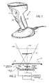
- FIG. 1 is a perspective view of a portable imaging system operative in either a handheld mode, or a hands-free mode, for capturing return light from targets;
- FIG. 2 is a schematic diagram of various components of the system of FIG. 1 ;
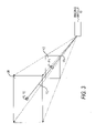
- FIG. 3 is a schematic diagram depicting operation of the system of FIG. 1 in accordance with the present invention.
- Reference numeral 30 in FIG. 1 generally identifies an imaging system or reader having a generally vertical window 26 and a gun-shaped housing 28 supported by a base 32 for supporting the imaging reader 30 on a countertop.
- the imaging reader 30 can thus be used in a hands-free mode as a stationary workstation in which products are slid, swiped past, or presented to, the vertical window 26 , or can be picked up off the countertop and held in an operator's hand and used in a handheld mode in which a trigger 34 is manually depressed to initiate imaging of indicia to be read.
- the base 32 can be omitted, and housings of other configurations can be employed.
- an imager 24 is mounted on a printed circuit board 22 in the reader.
- the imager 24 is a solid-state device, for example, a CCD or a CMOS imager, and has a one- or two-dimensional array of addressable image sensors or pixels operative for capturing return light captured and projected by an imaging lens assembly 20 along an optical path 46 through the window 26 .
- the return light is scattered and/or reflected from a system target 38 , for example, a one- and/or two-dimensional symbol, or a non-symbol target, over a field of view.
- the non-symbol target can be virtually anything, such as a person, place, or thing whose picture is to be acquired.
- the targets are located anywhere in a working range of distances between a close-in working distance (WD 1 ) and a far-out working distance (WD 2 ).
- WD 1 is about two inches from the imager array 24 and generally coincides with the window 26
- WD 2 can be many feet from the window 26 .
- a symbol target is located relatively close to the window 26
- a non-symbol target is located relatively further away from the window 26 . As described above, these different distances compromise the capability of the imaging system to rapidly acquire both non-symbol targets and symbol targets.
- An illuminator is also mounted in the imaging reader and preferably includes a light source, e.g., a laser or a light emitting diode (LED) 18 , and a collimating lens 16 for generating a collimated laser beam.
- a light source e.g., a laser or a light emitting diode (LED) 18
- a collimating lens 16 for generating a collimated laser beam.
- the imager 24 and the light source 18 are operatively connected to a controller or microprocessor 36 operative for controlling the operation of these components.
- a memory 14 is connected and accessible to the controller 36 .
- the microprocessor is the same as the one used for processing the return light from target symbols and for decoding the captured target images.
- the microprocessor 36 sends a command signal to pulse the light source 18 for a short time period, say 500 microseconds or less, and energizes and exposes the imager 24 to collect light from a target only during said time period.
- a typical array needs about 33 milliseconds to acquire the entire target image and operates at a frame rate of about 30 frames per second.
- the array may have on the order of one million addressable image sensors.
- the imager 24 , lens assembly 20 , laser 18 , collimating lens 16 , controller 36 and memory 14 are collectively depicted in FIG. 3 as an imaging module 10 .
- the laser 18 is operative for illuminating a calibration target 12 at a calibration distance d 1 with the collimated laser beam
- the imager 24 is operative for capturing return light of a calibration image size p 1 from the calibration target 12 .
- the controller 36 is operative for storing the calibration distance d 1 and the calibration image size p 1 in the memory 14 for subsequent retrieval and processing as known quantities.
- the laser 18 is operative for illuminating the system target 38 at a variable target distance d 2 with the collimated light beam
- the imager 24 is operative for capturing return light of a target image size p 2 from the system target 38 .
- the collimated light beam has a beam spot of a size s 1 during the calibration mode of operation, and a size S 2 during the imaging mode of operation.
- the beam spot has a diameter not less than two millimeters in diameter in a preferred embodiment to obtain good accuracy.
- the controller 36 is operative for determining the variable target distance d 2 based on the stored calibration distance d 1 and the stored calibration image size p 1 both of which are known in advance of the imaging mode, and the target image size p 2 .
- the controller 36 measures the calibration image size p 1 by counting a number of the sensors that captured light from the calibration target 12 during the calibration mode, and measures the target image size p 2 by counting a number of the sensors that captured light from the system target 38 during the imaging mode.
- the target image size p 2 is inversely linearly proportional to the variable target distance d 2 .
- the target image size p 2 changes accordingly; hence, the size of the target image size p 2 is indicative of the variable target distance d 2 .
- Resolution of an image is defined as the number of pixels per physical unit, e.g., length.
- the resolution r 1 of the calibration target 12 and the resolution r 2 of the system target 38 can be expressed as:
- the controller 36 is operative for determining the variable target distance d 2 by multiplying the stored calibration distance d 1 by the stored calibration image size p 1 divided by the target image size p 2 .
- the target distance d 2 can be used in many ways to enhance system performance and reliability.
- the value of the target distance d 2 can be used to adjust the focal length of the imaging lens assembly 20 for intelligent focusing. Whether the focus is or is not adjusted, this invention can achieve faster decode times and an extended range of working distances.
- the value of the target distance d 2 can be used to instruct the controller 36 to select the appropriate decoding algorithm to decode the target symbol.
- One algorithm can be used for close-in symbols, while another algorithm can be used for far-out symbols. The exact location of the beam spot on a target image is unimportant. Parallax is not a factor in the distance determination.
- the collimated light beam during the imaging mode of operation also advantageously serves as an aiming beam for targeting the system target.
Landscapes
- Physics & Mathematics (AREA)
- Engineering & Computer Science (AREA)
- General Physics & Mathematics (AREA)
- Electromagnetism (AREA)
- Remote Sensing (AREA)
- Radar, Positioning & Navigation (AREA)
- Computer Networks & Wireless Communication (AREA)
- General Health & Medical Sciences (AREA)
- Computer Vision & Pattern Recognition (AREA)
- Theoretical Computer Science (AREA)
- Artificial Intelligence (AREA)
- Toxicology (AREA)
- Health & Medical Sciences (AREA)
- Measurement Of Optical Distance (AREA)
- Optical Radar Systems And Details Thereof (AREA)
- Length Measuring Devices By Optical Means (AREA)
- Studio Devices (AREA)
Abstract
Description
- Solid-state imaging systems or readers have been used to electro-optically read targets, such as one-dimensional bar code symbols, particularly of the Universal Product Code (UPC) type, each having a row of bars and spaces spaced apart along one direction, and two-dimensional symbols, such as Code 49, which introduced the concept of vertically stacking a plurality of rows of bar and space patterns in a single symbol, as described in U.S. Pat. No. 4,794,239. Another two-dimensional code structure for increasing the amount of data that can be represented or stored on a given amount of surface area is known as PDF417, as described in U.S. Pat. No. 5,304,786.
- These solid-state imaging systems have also been used to capture images or pictures of a non-symbol target and include an imager having a one- or two-dimensional array of cells or photosensors, which correspond to image elements or pixels in a field of view of the imager. Such an imager may include a one- or two-dimensional charge coupled device (CCD) or a complementary metal oxide semiconductor (CMOS) device and associated circuits for producing electronic signals corresponding to a one- or two-dimensional array of pixel information over the field of view.
- It is therefore known to use a solid-state imaging system for capturing a monochrome image of a target symbol as, for example, disclosed in U.S. Pat. No. 5,703,349. It is also known to use a solid-state imaging system with multiple buried channels for capturing a full color image of the target as, for example, disclosed in U.S. Pat. No. 4,613,895. It is common to provide a two-dimensional CCD with a 640×480 resolution commonly found in VGA monitors, although other resolution sizes are possible.
- The design of a high performance imaging system for capturing the image of a target symbol and decoding the symbol, as well as capturing the image of a non-symbol target, presents many challenges. Symbols are generally located relatively close to the imager, whereas non-symbol targets whose pictures are to be taken are generally located relatively further away from the imager. Of course, in many applications, symbols themselves can be located anywhere within a wide range of working distances away from the imaging system.
- Optimal performance can be achieved using auto-focus/zoom optical systems to focus at different distances from the imager; however, these optical systems use extra sensors. For example, it is known to use a rangefinder of the infrared or ultrasonic type for determining the distance to the target, and to change the focal length of these optical systems based on the distance determined by the rangefinder. It is also known to use the parallax of an aiming spot to estimate target distance. However, in practice, such measures are relatively slow, add extra complexity and expense, and degrade system performance and reliability.
- One feature of the present invention resides, briefly stated, in an imaging system for, and a method of, determining a target distance to a system target located at variable distances from the system, without using a rangefinder, extra sensors or parallax. The system includes an illuminator, a solid-state imager having an array of image sensors, and a controller or microprocessor. The illuminator preferably includes a laser or a light emitting diode (LED) and a collimating lens for generating a collimated light beam.
- During a calibration mode of operation, the illuminator is operative for illuminating a calibration target at a calibration distance with the collimated light beam, and the imager is operative for capturing return light of a calibration image size from the calibration target. The controller is operative for storing the calibration distance and the calibration image size in a memory for subsequent retrieval and processing.
- During a subsequent imaging mode of operation, the illuminator is operative for illuminating the system target at the variable target distance with the collimated light beam, and the imager is operative for capturing return light of a target image size from the system target. The collimated light beam has a beam spot of a generally constant size during both modes of operation. The beam spot is generally circular and has a diameter not less than two millimeters in diameter in a preferred embodiment.
- The controller is operative for determining the variable target distance based on the stored calibration distance, the stored calibration image size, and the target image size. The target image size is inversely proportional to the variable target distance. The controller measures the calibration image size by counting a number of the sensors that captured light from the calibration target during the calibration mode, and measures the target image size by counting a number of the sensors that captured light from the system target during the imaging mode. The controller is operative for determining the variable target distance by multiplying the stored calibration distance by the stored calibration image size divided by the target image size. This enhances system performance and reliability.
- In a preferred embodiment, the system includes a housing having a window, and the illuminator is mounted in the housing and is operative for directing the collimated light beam through the window. The imager is also mounted in the housing and is operative for capturing the return light through the window. An imaging lens is advantageously provided for focusing the return light from the targets onto the image sensors. The collimated light beam during the imaging mode of operation also advantageously serves as an aiming beam for targeting the system target.
- The method of determining the target distance to the system target located at variable distances is performed by illuminating a calibration target at a calibration distance with a collimated light beam during a calibration mode of operation, illuminating the system target at the variable target distance with the collimated light beam during an imaging mode of operation, configuring the collimated light beam with a beam spot of a generally constant size during both modes of operation, capturing return light of a calibration image size from the calibration target during the calibration mode, capturing return light of a target image size from the system target during the imaging mode, and determining the variable target distance based on the calibration distance, the calibration image size, and the target image size. More specifically, the determining step is performed by determining the variable target distance by multiplying the calibration distance by the calibration image size divided by the target image size.
- The novel features which are considered as characteristic of the invention are set forth in particular in the appended claims. The invention itself, however, both as to its construction and its method of operation, together with additional objects and advantages thereof, will be best understood from the following description of specific embodiments when read in connection with the accompanying drawings.
-
FIG. 1 is a perspective view of a portable imaging system operative in either a handheld mode, or a hands-free mode, for capturing return light from targets; -
FIG. 2 is a schematic diagram of various components of the system ofFIG. 1 ; and -
FIG. 3 is a schematic diagram depicting operation of the system ofFIG. 1 in accordance with the present invention. -
Reference numeral 30 inFIG. 1 generally identifies an imaging system or reader having a generallyvertical window 26 and a gun-shaped housing 28 supported by abase 32 for supporting theimaging reader 30 on a countertop. Theimaging reader 30 can thus be used in a hands-free mode as a stationary workstation in which products are slid, swiped past, or presented to, thevertical window 26, or can be picked up off the countertop and held in an operator's hand and used in a handheld mode in which atrigger 34 is manually depressed to initiate imaging of indicia to be read. In another variation, thebase 32 can be omitted, and housings of other configurations can be employed. - As schematically shown in
FIG. 2 , animager 24 is mounted on a printedcircuit board 22 in the reader. Theimager 24 is a solid-state device, for example, a CCD or a CMOS imager, and has a one- or two-dimensional array of addressable image sensors or pixels operative for capturing return light captured and projected by animaging lens assembly 20 along anoptical path 46 through thewindow 26. The return light is scattered and/or reflected from asystem target 38, for example, a one- and/or two-dimensional symbol, or a non-symbol target, over a field of view. The non-symbol target can be virtually anything, such as a person, place, or thing whose picture is to be acquired. The targets are located anywhere in a working range of distances between a close-in working distance (WD1) and a far-out working distance (WD2). In a preferred embodiment, WD1 is about two inches from theimager array 24 and generally coincides with thewindow 26, and WD2 can be many feet from thewindow 26. Typically, a symbol target is located relatively close to thewindow 26, whereas a non-symbol target is located relatively further away from thewindow 26. As described above, these different distances compromise the capability of the imaging system to rapidly acquire both non-symbol targets and symbol targets. - An illuminator is also mounted in the imaging reader and preferably includes a light source, e.g., a laser or a light emitting diode (LED) 18, and a
collimating lens 16 for generating a collimated laser beam. As shown inFIG. 2 , theimager 24 and thelight source 18 are operatively connected to a controller ormicroprocessor 36 operative for controlling the operation of these components. Amemory 14 is connected and accessible to thecontroller 36. Preferably, the microprocessor is the same as the one used for processing the return light from target symbols and for decoding the captured target images. - In operation, the
microprocessor 36 sends a command signal to pulse thelight source 18 for a short time period, say 500 microseconds or less, and energizes and exposes theimager 24 to collect light from a target only during said time period. A typical array needs about 33 milliseconds to acquire the entire target image and operates at a frame rate of about 30 frames per second. The array may have on the order of one million addressable image sensors. - The
imager 24,lens assembly 20,laser 18, collimatinglens 16,controller 36 andmemory 14 are collectively depicted inFIG. 3 as animaging module 10. During a calibration mode of operation, thelaser 18 is operative for illuminating acalibration target 12 at a calibration distance d1 with the collimated laser beam, and theimager 24 is operative for capturing return light of a calibration image size p1 from thecalibration target 12. Thecontroller 36 is operative for storing the calibration distance d1 and the calibration image size p1 in thememory 14 for subsequent retrieval and processing as known quantities. - During an imaging mode of operation, also shown in
FIG. 3 , thelaser 18 is operative for illuminating thesystem target 38 at a variable target distance d2 with the collimated light beam, and theimager 24 is operative for capturing return light of a target image size p2 from thesystem target 38. The collimated light beam has a beam spot of a size s1 during the calibration mode of operation, and a size S2 during the imaging mode of operation. The beam spot is generally circular and has a generally constant size, that is, s1=s2 throughout the range of working distances. The beam spot has a diameter not less than two millimeters in diameter in a preferred embodiment to obtain good accuracy. - The
controller 36 is operative for determining the variable target distance d2 based on the stored calibration distance d1 and the stored calibration image size p1 both of which are known in advance of the imaging mode, and the target image size p2. Thecontroller 36 measures the calibration image size p1 by counting a number of the sensors that captured light from thecalibration target 12 during the calibration mode, and measures the target image size p2 by counting a number of the sensors that captured light from thesystem target 38 during the imaging mode. - The target image size p2 is inversely linearly proportional to the variable target distance d2. When the distance between the
system target 38 and themodule 10 changes, the target image size p2 changes accordingly; hence, the size of the target image size p2 is indicative of the variable target distance d2. The larger the target image size p2 (measured in pixels), the closer is thesystem target 38. - Resolution of an image is defined as the number of pixels per physical unit, e.g., length. Thus, the resolution r1 of the
calibration target 12 and the resolution r2 of thesystem target 38 can be expressed as: -
r 1 /r 2 =d 2 /d 1 (1) -
From geometry, it is known that: -
s 1 =p 1 /r 1 (2) -
and -
s 2 =p 2 /r 2 (3) - As noted above, since the physical size of the beam spot is substantially constant over a wide range, then:
-
s1=s2 (4) -
Solving equations (1) to (4), we get: -
d 2 =d 1 *p 1 /p 2 (5) - In other words, the
controller 36 is operative for determining the variable target distance d2 by multiplying the stored calibration distance d1 by the stored calibration image size p1 divided by the target image size p2. - Once the target distance d2 is known, it can be used in many ways to enhance system performance and reliability. For example, the value of the target distance d2 can be used to adjust the focal length of the
imaging lens assembly 20 for intelligent focusing. Whether the focus is or is not adjusted, this invention can achieve faster decode times and an extended range of working distances. Also, the value of the target distance d2 can be used to instruct thecontroller 36 to select the appropriate decoding algorithm to decode the target symbol. One algorithm can be used for close-in symbols, while another algorithm can be used for far-out symbols. The exact location of the beam spot on a target image is unimportant. Parallax is not a factor in the distance determination. - The collimated light beam during the imaging mode of operation also advantageously serves as an aiming beam for targeting the system target.
- It will be understood that each of the elements described above, or two or more together, also may find a useful application in other types of constructions differing from the types described above. Thus, imaging systems having different configurations can be used.
- While the invention has been illustrated and described as determining target distance in an imaging reader, it is not intended to be limited to the details shown, since various modifications and structural changes may be made without departing in any way from the spirit of the present invention.
- Without further analysis, the foregoing will so fully reveal the gist of the present invention that others can, by applying current knowledge, readily adapt it for various applications without omitting features that, from the standpoint of prior art, fairly constitute essential characteristics of the generic or specific aspects of this invention and, therefore, such adaptations should and are intended to be comprehended within the meaning and range of equivalence of the following claims.
Claims (21)
Priority Applications (1)
| Application Number | Priority Date | Filing Date | Title |
|---|---|---|---|
| US12/008,460 US7679724B2 (en) | 2008-01-11 | 2008-01-11 | Determining target distance in imaging reader |
Applications Claiming Priority (1)
| Application Number | Priority Date | Filing Date | Title |
|---|---|---|---|
| US12/008,460 US7679724B2 (en) | 2008-01-11 | 2008-01-11 | Determining target distance in imaging reader |
Publications (2)
| Publication Number | Publication Date |
|---|---|
| US20090180098A1 true US20090180098A1 (en) | 2009-07-16 |
| US7679724B2 US7679724B2 (en) | 2010-03-16 |
Family
ID=40850356
Family Applications (1)
| Application Number | Title | Priority Date | Filing Date |
|---|---|---|---|
| US12/008,460 Active US7679724B2 (en) | 2008-01-11 | 2008-01-11 | Determining target distance in imaging reader |
Country Status (1)
| Country | Link |
|---|---|
| US (1) | US7679724B2 (en) |
Families Citing this family (1)
| Publication number | Priority date | Publication date | Assignee | Title |
|---|---|---|---|---|
| US10248886B2 (en) * | 2013-10-30 | 2019-04-02 | Pgs Geophysical As | System and method for underwater distance measurement |
Citations (4)
| Publication number | Priority date | Publication date | Assignee | Title |
|---|---|---|---|---|
| US4530600A (en) * | 1982-02-22 | 1985-07-23 | Northrop Corporation | Variable attenuator for optical transceiver |
| US5886775A (en) * | 1997-03-12 | 1999-03-23 | M+Ind | Noncontact digitizing imaging system |
| US20040240754A1 (en) * | 2001-06-29 | 2004-12-02 | Smith Melvyn Lionel | Overhead dimensioning system and method |
| US20050213075A1 (en) * | 2001-12-14 | 2005-09-29 | Cooke Bradly J | Target identification system and method |
-
2008
- 2008-01-11 US US12/008,460 patent/US7679724B2/en active Active
Patent Citations (4)
| Publication number | Priority date | Publication date | Assignee | Title |
|---|---|---|---|---|
| US4530600A (en) * | 1982-02-22 | 1985-07-23 | Northrop Corporation | Variable attenuator for optical transceiver |
| US5886775A (en) * | 1997-03-12 | 1999-03-23 | M+Ind | Noncontact digitizing imaging system |
| US20040240754A1 (en) * | 2001-06-29 | 2004-12-02 | Smith Melvyn Lionel | Overhead dimensioning system and method |
| US20050213075A1 (en) * | 2001-12-14 | 2005-09-29 | Cooke Bradly J | Target identification system and method |
Also Published As
| Publication number | Publication date |
|---|---|
| US7679724B2 (en) | 2010-03-16 |
Similar Documents
| Publication | Publication Date | Title |
|---|---|---|
| US8910872B2 (en) | Imaging reader and method with dual function illumination light assembly | |
| US8056808B2 (en) | Arrangement for and method of controlling image capture parameters in response to motion of an imaging reader | |
| US8534556B2 (en) | Arrangement for and method of reducing vertical parallax between an aiming pattern and an imaging field of view in a linear imaging reader | |
| US8618468B2 (en) | Imaging module with folded illuminating and imaging paths | |
| US10534944B1 (en) | Method and apparatus for decoding multiple symbology types | |
| US20100078483A1 (en) | Arrangement for and method of generating uniform distributed line pattern for imaging reader | |
| EP2401698B1 (en) | Compact imaging engine for imaging reader | |
| US20090272808A1 (en) | Imaging module with optical elements of one-piece construction | |
| US9010643B2 (en) | Selective working distance range restriction in imaging system | |
| US20100147957A1 (en) | Range finding in imaging reader for electro-optically reading indicia | |
| US8740080B2 (en) | Imaging reader for and method of receipt acknowledgment and symbol capture | |
| US8006906B2 (en) | Arrangement for and method of generating uniform distributed line pattern for imaging reader | |
| US7679724B2 (en) | Determining target distance in imaging reader | |
| US20100096462A1 (en) | Arrangement for and method of enhancing performance of an imaging reader | |
| EP2140398B1 (en) | Image enhancement in imaging system | |
| EP2542999B1 (en) | Data capture terminal with automatic focusing over a limited range of working distances | |
| US20080023555A1 (en) | Aperture stop in imaging reader |
Legal Events
| Date | Code | Title | Description |
|---|---|---|---|
| AS | Assignment |
Owner name: SYMBOL TECHNOLOGIES, INC., NEW YORK Free format text: ASSIGNMENT OF ASSIGNORS INTEREST;ASSIGNORS:WANG, DAYOU;YU, MING;REEL/FRAME:020413/0149 Effective date: 20071217 Owner name: SYMBOL TECHNOLOGIES, INC.,NEW YORK Free format text: ASSIGNMENT OF ASSIGNORS INTEREST;ASSIGNORS:WANG, DAYOU;YU, MING;REEL/FRAME:020413/0149 Effective date: 20071217 |
|
| STCF | Information on status: patent grant |
Free format text: PATENTED CASE |
|
| CC | Certificate of correction | ||
| FPAY | Fee payment |
Year of fee payment: 4 |
|
| AS | Assignment |
Owner name: MORGAN STANLEY SENIOR FUNDING, INC. AS THE COLLATERAL AGENT, MARYLAND Free format text: SECURITY AGREEMENT;ASSIGNORS:ZIH CORP.;LASER BAND, LLC;ZEBRA ENTERPRISE SOLUTIONS CORP.;AND OTHERS;REEL/FRAME:034114/0270 Effective date: 20141027 Owner name: MORGAN STANLEY SENIOR FUNDING, INC. AS THE COLLATE Free format text: SECURITY AGREEMENT;ASSIGNORS:ZIH CORP.;LASER BAND, LLC;ZEBRA ENTERPRISE SOLUTIONS CORP.;AND OTHERS;REEL/FRAME:034114/0270 Effective date: 20141027 |
|
| AS | Assignment |
Owner name: SYMBOL TECHNOLOGIES, LLC, NEW YORK Free format text: CHANGE OF NAME;ASSIGNOR:SYMBOL TECHNOLOGIES, INC.;REEL/FRAME:036083/0640 Effective date: 20150410 |
|
| AS | Assignment |
Owner name: SYMBOL TECHNOLOGIES, INC., NEW YORK Free format text: RELEASE BY SECURED PARTY;ASSIGNOR:MORGAN STANLEY SENIOR FUNDING, INC.;REEL/FRAME:036371/0738 Effective date: 20150721 |
|
| MAFP | Maintenance fee payment |
Free format text: PAYMENT OF MAINTENANCE FEE, 8TH YEAR, LARGE ENTITY (ORIGINAL EVENT CODE: M1552) Year of fee payment: 8 |
|
| MAFP | Maintenance fee payment |
Free format text: PAYMENT OF MAINTENANCE FEE, 12TH YEAR, LARGE ENTITY (ORIGINAL EVENT CODE: M1553); ENTITY STATUS OF PATENT OWNER: LARGE ENTITY Year of fee payment: 12 |