US2008317A - Wood slicing machine - Google Patents
Wood slicing machine Download PDFInfo
- Publication number
- US2008317A US2008317A US744038A US74403834A US2008317A US 2008317 A US2008317 A US 2008317A US 744038 A US744038 A US 744038A US 74403834 A US74403834 A US 74403834A US 2008317 A US2008317 A US 2008317A
- Authority
- US
- United States
- Prior art keywords
- knife
- block
- rest
- slicing
- cutting
- Prior art date
- Legal status (The legal status is an assumption and is not a legal conclusion. Google has not performed a legal analysis and makes no representation as to the accuracy of the status listed.)
- Expired - Lifetime
Links
- 239000002023 wood Substances 0.000 title description 12
- 238000005520 cutting process Methods 0.000 description 38
- 230000005484 gravity Effects 0.000 description 2
- 239000011121 hardwood Substances 0.000 description 2
- 235000006629 Prosopis spicigera Nutrition 0.000 description 1
- 240000000037 Prosopis spicigera Species 0.000 description 1
- 238000010276 construction Methods 0.000 description 1
- 230000007423 decrease Effects 0.000 description 1
- 239000000835 fiber Substances 0.000 description 1
- 230000001788 irregular Effects 0.000 description 1
- 239000011435 rock Substances 0.000 description 1
Images


Classifications
-
- B—PERFORMING OPERATIONS; TRANSPORTING
- B27—WORKING OR PRESERVING WOOD OR SIMILAR MATERIAL; NAILING OR STAPLING MACHINES IN GENERAL
- B27L—REMOVING BARK OR VESTIGES OF BRANCHES; SPLITTING WOOD; MANUFACTURE OF VENEER, WOODEN STICKS, WOOD SHAVINGS, WOOD FIBRES OR WOOD POWDER
- B27L5/00—Manufacture of veneer ; Preparatory processing therefor
- B27L5/06—Cutting strips from a stationarily- held trunk or piece by a rocking knife carrier, or from rocking trunk or piece by a stationarily-held knife carrier; Veneer- cutting machines
Definitions
- My invention relates to a machine used for slic-' ing thin strips from a block of wood, such strips as used in the making of boxes, or for-veneers or similar purposes.
- the slicing is done by means of a heavy knife; the block which is to be sliced is generally first treated with steam and heat and is placed on the shelf or block sup-- port provided in the machine, the block being further supported by a back-rest during the slicing operation.
- the cutting edge of the knife and that such holding of the block may be accomplished by subjectingthe block to lateral pressure, that is, to a pressure more or less perpendicular to a cutting plane of the knife. Without imposing this lateral pressure on the block during this cutting operationof the knife, the irregular fibers of .the wood often tend to cause heavy and uneven slices, and the cutting of thin slices is difficult.
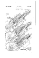
- Fig. 1 is a perspective elevation with the slicing knife in raised position
- Fig. 2 is alarger scale'vertical sectionofmymaof my machine chine approximatelytaken on the line pointed by the arrow2 in Fig. 1;
- Fig. 3 is a, still larger scale front elevation of my :machine looking in the direction pointed by the arrow 3.in Fig. 2; v
- Fig. 4 is a fragmentary detail of the upper part I of mymachine as shown in Fig. 3;
- Figs. .5, 6 and 7 are'fragmentary, more or less diagrammaticvertical sections of my machine illustrating in their order relative positions of the wooden block, the block support or shelf, the back-rest for th'erblo'ck, and the slicing knife, during the cutting operation of the latter.
- Fig. 5 shows the position of said parts beforethe beginning of the slicing operation
- Fig. 6 shows their position when. the slicing operation is one-half completed
- Fig; 7 shows their position when the slicing operation is completed.
- My machine comprises a sup'porting'frame consisting of side uprights a, w having bases b and braces c and (I connected to the side uprights by bolts 0' and dflrespectively.
- a shaft e journaled. in the side uprights a, are attached heavy disks f and 7", one of which, 1, is driven by means of belts g from a pulley h, driven by any suitable means, forexample amotor (not shown)
- the disks jand f are connected by articulated arms 7 and 7", to the ends of the rod 12, which carries .the upper endof the frame k, to which is fastened the back-rest m (see Figs.
- the slicing knife 10 is fastened to the bar 0 v by screws p and the bar 0 in turn is attached to the, frame is by a pair of bolts q passing from the frame is thru the slots q in the ends of the bar 0.
- the frame 70 is adapted to slideinguides't, each composed of a top and bottom member, which members are bolted together, and each bottom member-is also screwed to an upright a.
- slideinguides't each composed of a top and bottom member, which members are bolted together, and each bottom member-is also screwed to an upright a.
- These guide tracks maybe made with removable linings t held in place by screws t2 *to permit the linings to be renewed when required by wear. As shown by Figs.
- the sides of frame 10 are not perpendicular to the rod 11 and the guide tracks t are so arranged as to permit the frame is to slide obliquely with reference to the uprights a in order that the knife p will make a slicing cut.
- the topof the frame is comprises a cross bar 1c and one of the frame members 0 also is provided at its top. with a cross bar 02.
- Rods u are rigidly supported by said cross car 02 and are slidably supported in said cross bar it.
- On the rods u are mounted expansion springs 12. It will be seen from Figs.
- the supporting shelf 2 which holds the block of wood during the slicing, is made with a front apron or flange 3 for convenience in sliding the block of wood on to the shelf.
- The'shelf2 is firmly bolted to the rocker arms 4, the lower ends of which are provided with journal boxes 5 in whichbear cams 6 rigidly mounted on the shaft 6.
- rocker arms 4 are provided with guide webs 4a, see,Figs.f5, Gand '7, adapted to slide on a roller I3 mounted on a pin 1 attachedto the frame upright a, thus enabling the .rocker arm 4, and therewith the block supporting shelf 2, to rock and move towards and away from the back-rest in coincidence with the rotation of the cams 6 on the shaft e.
- the shelf 2 is provided with a slot 8 in which is inserted a strip of hard wood 9 adjustable by set screws It.
- This strip-9 serves as the bottom cutting surface for'the slicing knife.
- the backrest m is provided with a series of ribs m which, as shown inFigs. 5,76 and 7, recede downward from a place parallel with the front face of the knifep;
- FIG. 5 The manner in which myslicing machine op erates is illustrated in Figs. 5, 6 and 7.
- Fig. 5 the block of wood ll, ready for slicing, has been placed on the supporting shelf 2, and, since this shelf is inclinedbackward at an angle of about the block of wood is causedto slide down by gravityand rest against the upper ends of the ribsm' of the back-rest m.
- the slicing knife 1) as seen in Fig. 5, is in raised position and ready for its downward cutting stroke. 1
- the shaft e and cams 6 turn in a ,clockwise direction, as indicated by the arrow.
- lateral pressure is exactly where the slicing is taking place.
- I claim: 7 1. In a wooden block slicing machine the combination of a 'reciprocated slicing knife, a movable support and a back-rest for the block, the
- back-rest moving with the knife and adapted to 'provide a bearing for the block at a point ap proximately coinciding with the cutting edge of the knife, and means'for reciprocating said knife and for moving said block support towards and from the back-rest in synchronism with the cutting and return movements of the knife, whereby the block support constantly causes lateral pressure of the block against the back-rest at the 'pointwhere the knife is cutting thru the block,
- a reciprocated slicing knife a support and a back-rest for the block, the back-rest moving with the knife and adapted to provide a bearing for the block at a point slightly below the cutting edge of the knife, and means for reciprocating said knife and for moving said block support towards and from the back-rest in synchronism with the cutting and return movements of the knife, whereby the block support constantly causes lateral pressure of the block against the back-rest at the point where the knife is cutting thru the block, and said pressure is removed during the return movement of the knife.
- a reciprocated slicing knife a support and a back-rest for the block, the supporting face of the block support sloping inward, the back-rest moving with the knife and adapted to provide a bearing for the block at a point approximately coinciding with the cutt'mg edge of the knife, and means for reciprocating said knife and for moving said block support towards and from the back-rest in synchronism with the cutting and return movements of the knife, whereby the block support constantly causes lateral pressure of the block against the back-rest at the point where the knife is cutting thru the block, and said pressure is removed during the return movement of the knife.
- a reciprocated slicing knife, a sup port and a back-rest for the block the supporting face of the block support sloping inward, the back-rest moving with the knife, the bearing face of the back-rest receding downwardly from a plane parallel to the plane of the knife, and adapted to provide a bearing for the block at a point approximately coinciding with the cutting edge of the knife, whereby the block support constantly causes lateral pressure of the block against the back-rest at the point where the knife is cutting thru the block, and said pressure is removed during the return movement of the knife.
- a reciprocated slicing knife a block support having angular movement with respect to the plane of the slicing knife, the supporting face of the block support sloping inward, a backrest for the block, said back-rest moving with the knife and adapted to provide a bearing for the block at a point approximately coinciding with the cutting edge of the knife, and means for synchronizing said angular movement of the block support with the cutting and return movements of the knife, whereby the block support causes lateral pressure of the block against the back-rest at the point where the knife is cutting thru the block, and said pressure is removed during the return movement of the knife.
- a reciprocated slicing knife the combination of a reciprocated slicing knife, arms pivoted at one end and supported by a cam at the other, a block support carried by said arms, the supporting face of the block support sloping inward, a back-rest for the block, said back-rest moving with the knife and adapted to provide a bearing for the block at a point approximately coinciding with the cutting edge of the knife, and means for synchronizing the operation of said cam with the cuttingandreturn movements of the knife, whereby the block support causes lateral pressure of the block against the backrest at the point where the knife is cutting thru the block, and said pressure is removed during the return movement of the knife.
- a frame including inclined uprights, a carrier'mounted on said frame, and longitudinally obliquely reciprocable, a slicing-knife and a back-rest carried by said carrier, at block support mounted on the frame, the supporting face of said block support arranged perpendicular to the plane of said knife, and means for reciprocating said carrier and moving said block support towards and from the back-rest in synchronism with the cutting and return movements of the knife.
- a frame including inclined uprights, a carrier mounted on said frame, and longitudinally obliquely reciprocable, a slicing-knife and a backrest carried by said carrier, arms pivotally and slidably supported at one end on said frame, a rotary cam element supporting the other end of said arms, a block support carried by said arms, the supporting face of said support arranged perpendicular to the plane of said knife, means for reciprocating said carrier and for rotating said cams, whereby to move the block support towards and from the back-rest in synchronism with the cutting and return movements of the knife.
- a. wooden block slicing machine the combination of a reciprocated slicing knife, a block support having angular movement with respect to the plane of the slicingknife, the supporting face of the block support sloping inward, a back-rest for the block, said back-rest moving with the knife, the bearing face of the back-rest receding downwardly from a plane parallel to the plane of the knife and adapted to provide a bearing for the block at a point approximately coinciding with the cutting edge of the knife, and means for synchronizing said angular movement of the block support with the cutting and return movements of the knife, whereby the block support causes lateral pressure of the block against the back-rest at the point where the knife is cutting thru the block, and said pressure is removed during the return movement of the knife.
Landscapes
- Engineering & Computer Science (AREA)
- Life Sciences & Earth Sciences (AREA)
- Manufacturing & Machinery (AREA)
- Wood Science & Technology (AREA)
- Forests & Forestry (AREA)
- Manufacture Of Wood Veneers (AREA)
Description
Filed Sept. 14, 1954 5 Sheets-$heet 1 M W, M/ i m m/ Jufiy 16, 1935.
F. J. VOIGT WOOD SLICING MACHINE Filed SepL 14, 1934 lllIHl 1| 5 Sheets-Sheet 2 July 16, 1935. F. J. VOIGT WOOD SLICING MACHINE Filed Sept. 14, 1954 3 SheetsSheet 5 I I II I I Patented July 16, 1935 UNITED STATES PAT ENT OFFICE 1 My invention relates to a machine used for slic-' ing thin strips from a block of wood, such strips as used in the making of boxes, or for-veneers or similar purposes. r
In machines of this character the slicing is done by means of a heavy knife; the block which is to be sliced is generally first treated with steam and heat and is placed on the shelf or block sup-- port provided in the machine, the block being further supported by a back-rest during the slicing operation.
I have discovered that in order to insure that the slices cut from the block will be straight and clean, and also to facilitate the cutting of thin slices, it is necessary that the block be firmly held against the back-rest during the cutting operation at a point approximately coinciding with,
the cutting edge of the knife; and that such holding of the block may be accomplished by subjectingthe block to lateral pressure, that is, to a pressure more or less perpendicular to a cutting plane of the knife. Without imposing this lateral pressure on the block during this cutting operationof the knife, the irregular fibers of .the wood often tend to cause heavy and uneven slices, and the cutting of thin slices is difficult.
I have further discovered that it is desirable to have the block fed automatically against the back-rest, constantly holding it against the latter, and that this may be practically accomplished by arranging the supporting face of the block sup port so as to decline at an angle, thus causing gravity to draw the block against the back-rest when the block is not engaged by the knife.
I have further discovered that strong lateral pressure between the block and back-rest may be developed by making the block support movable towards and from the back-wrest and providing means for synchronizing movementtowards'the back-rest with the cutting movement of the knife and movement away from the back-rest" with the return movement of the knife, thus causing said pressure to be applied during the cutting move- 'ment of the knife andwithdrawing such pressure during the return movement of the knife.
The objects of my invention are to incorporate in a wooden block slicing machine the above mentioned features, and I attain the objects by the ;devices and combinations hereinafter fully described with reference to the accompanying drawings.
In such drawings:
Fig. 1 is a perspective elevation with the slicing knife in raised position;
i Fig. 2 is alarger scale'vertical sectionofmymaof my machine chine approximatelytaken on the line pointed by the arrow2 in Fig. 1;
Fig. 3 is a, still larger scale front elevation of my :machine looking in the direction pointed by the arrow 3.in Fig. 2; v
Fig. 4 is a fragmentary detail of the upper part I of mymachine as shown in Fig. 3; and
Figs. .5, 6 and 7, are'fragmentary, more or less diagrammaticvertical sections of my machine illustrating in their order relative positions of the wooden block, the block support or shelf, the back-rest for th'erblo'ck, and the slicing knife, during the cutting operation of the latter. Thus Fig. 5 shows the position of said parts beforethe beginning of the slicing operation; Fig. 6 shows their position when. the slicing operation is one-half completed; and Fig; 7 shows their position when the slicing operation is completed.
My machine comprises a sup'porting'frame consisting of side uprights a, w having bases b and braces c and (I connected to the side uprights by bolts 0' and dflrespectively. To both ends of a shaft e, journaled. in the side uprights a, are attached heavy disks f and 7", one of which, 1, is driven by means of belts g from a pulley h, driven by any suitable means, forexample amotor (not shown) The disks jand f are connected by articulated arms 7 and 7", to the ends of the rod 12, which carries .the upper endof the frame k, to which is fastened the back-rest m (see Figs. 3 and 4) and the supporting bar 0 of the slicing knife 10.. The slicing knife 10 is fastened to the bar 0 v by screws p and the bar 0 in turn is attached to the, frame is by a pair of bolts q passing from the frame is thru the slots q in the ends of the bar 0.
.These slots q enable a slight adjustment to be madein the positionof the bar 0 when the bolts q are loosen-ed, such adjustment beingregulated by the set screws 1', r threaded in the lugs s on the frame k, the said set screws 1*, r bearing against the ends of thebar o. 1 The frame 70 is adapted to slideinguides't, each composed of a top and bottom member, which members are bolted together, and each bottom member-is also screwed to an upright a. These guide tracks maybe made with removable linings t held in place by screws t2 *to permit the linings to be renewed when required by wear. As shown by Figs. 3 and 4, the sides of frame 10 are not perpendicular to the rod 11 and the guide tracks t are so arranged as to permit the frame is to slide obliquely with reference to the uprights a in order that the knife p will make a slicing cut. The topof the frame is comprises a cross bar 1c and one of the frame members 0 also is provided at its top. with a cross bar 02. Rods u are rigidly supported by said cross car 02 and are slidably supported in said cross bar it. On the rods u are mounted expansion springs 12. It will be seen from Figs. 1 and 3 that each revolution of the disks I, J" will cause the articulated arms :i, 7" to pull the rod 2 and therewith the frame It, the back-rest m and the slicing knife p down for cutting one slice (as shown by l2) off the block I I. With the downward movement of the frame It the rods u will be projected thru the holes in the upper cross bar It and thus compress the springs 11. With the lifting movement of the arms 1', 7'" and the return of the frame It and therewith the knife and back-rest'to normal or initial position during the completion of the 'revolution of the disks f, f, these springs 12 will be expanded. v i 3 The supporting shelf 2, which holds the block of wood during the slicing, is made with a front apron or flange 3 for convenience in sliding the block of wood on to the shelf. The'shelf2 is firmly bolted to the rocker arms 4, the lower ends of which are provided with journal boxes 5 in whichbear cams 6 rigidly mounted on the shaft 6. The upper ends of the rocker arms 4 are provided with guide webs 4a, see,Figs.f5, Gand '7, adapted to slide on a roller I3 mounted on a pin 1 attachedto the frame upright a, thus enabling the .rocker arm 4, and therewith the block supporting shelf 2, to rock and move towards and away from the back-rest in coincidence with the rotation of the cams 6 on the shaft e.
i The shelf 2 is provided with a slot 8 in which is inserted a strip of hard wood 9 adjustable by set screws It. This strip-9 serves as the bottom cutting surface for'the slicing knife. The backrest m is provided with a series of ribs m which, as shown inFigs. 5,76 and 7, recede downward from a place parallel with the front face of the knifep;
The manner in which myslicing machine op erates is illustrated in Figs. 5, 6 and 7. In Fig. 5 the block of wood ll, ready for slicing, has been placed on the supporting shelf 2, and, since this shelf is inclinedbackward at an angle of about the block of wood is causedto slide down by gravityand rest against the upper ends of the ribsm' of the back-rest m. The slicing knife 1), as seen in Fig. 5, is in raised position and ready for its downward cutting stroke. 1
As further shown by Fig. 5, the angle made by the supporting. shelf'2 with the back-rest m and also with the blade of the knife 1; at this instance isslightly less than 90. This causes theblock of wood I i, which is of rectangular cross section, to bear against the back-rest at the upper end ,only, and this is also accentuated by the fact that the ribs m of the'back-restlm recede slightly downward. The shaft e and cams 6 turn in a ,clockwise direction, as indicated by the arrow.
When the edge of the slicing knife strikes the top of the block I l it will exert such pressure on the :block as would ordinarily be sufficient to prevent any outward sliding of the block on the supporting, shelf 2 away from the back-rest. When the slicing knife descends, however, the back-rest descendswith it, and at the same time the cams 'ii'cause the supporting shelf 2 to be moved inward. and into the position shown in Fig. 6. In
'this position the slicing knifeis half way thru the block; Thedownward force of the knife blade holds the block firmly on the shelf, but the inward movement of the shelf causes'great lateral pressure to be exerted against the top of theribs m by the rear face of the block. The angle made by the top of the shelf 2 with the plane of the slicing knife 10 has also become slightly greater.
lateral pressure is exactly where the slicing is taking place.
' Referring now to Fig. 7, it will be seen that the slicing knife p has completed its downward stroke and has reached the strip of hardwood 9. The
back-rest has passed below the back of the shelf "2 leaving the strip of wood i2 which has been sliced off free to fall down behind the machine. The journals 5 and the bottoms of the supports 4 "are in their extreme inward position. The angle :made by the shelf 2 with the plane of the slicing knife p is slightly greater than 90". It will be noticedthat the rear face of the block I! does not touch the knife blade at the top, consequently, as -the knife blade is drawn upward, there will very little friction between knife blade and wood block, which would round off and wear away the cutting edge of the knife blade. When the knife blade again reaches its position above the block II, the force of gravity will cause the block ll once more to slide back against the ribs m of .the back-rest m and block slicing knife'andbackrest are again in the-position indicated by Fig, 5.
Referring again to Fig. 3, it is clearly seen that due to the diagonal downward movement of the frame It and slicing knife p the knife has an oblique cutting motion; while this is not absolutely necessary and my machine would work also if the knife descended in a line at right angles to the shelf and block, I have found that this oblique I have found it possible with the construction g described to run my machine ata very high rate of speed; I have been able to make thin, even .slices and to cut the blocks quite close to the front face. It is, of course, desirable to turn the blocks if it is not required to have the slices all of the same width, and this can be done without even stopping the machine. By removing such a large percentage of the friction between the face of the slicing knife and the rear face of the block during the upward movement of the knife, I have found that the life of the cutting edge of the slicing knife is very materially lengthenedf By making the wheels) and I very heavy,
by having springs u on the rods by having the diameter of the pulley h small in comparison to that of the wheels I and f and by running my machine at a high rate of speed, I have found that a very even, regular movement is obtained .and the machine has proven itself'by repeated tests to be highly satisfactory.
I claim: 7 1. In a wooden block slicing machine the combination of a 'reciprocated slicing knife, a movable support and a back-rest for the block, the
back-rest moving with the knife and adapted to 'provide a bearing for the block at a point ap proximately coinciding with the cutting edge of the knife, and means'for reciprocating said knife and for moving said block support towards and from the back-rest in synchronism with the cutting and return movements of the knife, whereby the block support constantly causes lateral pressure of the block against the back-rest at the 'pointwhere the knife is cutting thru the block,
and said pressure is removed during the return movement of the knife.
2. In a wooden block slicing machine the combination of a reciprocated slicing knife, a support and a back-rest for the block, the back-rest moving with the knife and adapted to provide a bearing for the block at a point slightly below the cutting edge of the knife, and means for reciprocating said knife and for moving said block support towards and from the back-rest in synchronism with the cutting and return movements of the knife, whereby the block support constantly causes lateral pressure of the block against the back-rest at the point where the knife is cutting thru the block, and said pressure is removed during the return movement of the knife.
3. In a wooden block slicing machine the combination of a reciprocated slicing knife, a support and a back-rest for the block, the supporting face of the block support sloping inward, the back-rest moving with the knife and adapted to provide a bearing for the block at a point approximately coinciding with the cutt'mg edge of the knife, and means for reciprocating said knife and for moving said block support towards and from the back-rest in synchronism with the cutting and return movements of the knife, whereby the block support constantly causes lateral pressure of the block against the back-rest at the point where the knife is cutting thru the block, and said pressure is removed during the return movement of the knife.
4. In a wooden block slicing machine the combination of a reciprocated slicing knife, a sup port and a back-rest for the block, the supporting face of the block support sloping inward, the back-rest moving with the knife, the bearing face of the back-rest receding downwardly from a plane parallel to the plane of the knife, and adapted to provide a bearing for the block at a point approximately coinciding with the cutting edge of the knife, whereby the block support constantly causes lateral pressure of the block against the back-rest at the point where the knife is cutting thru the block, and said pressure is removed during the return movement of the knife.
5. In a wooden block slicing machine the combination of a reciprocated slicing knife, a rockable support and a back-rest for the block, the supporting face of the block-support sloping inward, the back rest moving with the knife, the
bearing face of the back-rest receding downwardly from a plane parallel to the plane of the knife and adapted to provide a bearing for the block at a point slightly below the cutting edge of the knife, and means for reciprocating said knife and for moving said block support towards and from the back-rest in synchronism with the cutting and return movements of the knife, whereby the block support constantly causes lateral pressure of the block against the back-rest at the point where the knife is cutting thru the block, and said pressure is removed during the return movement of the knife.
6. In a wooden block slicing machine the combination of a reciprocated slicing knife, a block support having angular movement with respect to the plane of the slicing knife, the supporting face of the block support sloping inward, a backrest for the block, said back-rest moving with the knife and adapted to provide a bearing for the block at a point approximately coinciding with the cutting edge of the knife, and means for synchronizing said angular movement of the block support with the cutting and return movements of the knife, whereby the block support causes lateral pressure of the block against the back-rest at the point where the knife is cutting thru the block, and said pressure is removed during the return movement of the knife.
7. In a wooden block slicing machine the combination of a reciprocated slicing knife, arms pivoted at one end and supported by a cam at the other, a block support carried by said arms, the supporting face of the block support sloping inward, a back-rest for the block, said back-rest moving with the knife and adapted to provide a bearing for the block at a point approximately coinciding with the cutting edge of the knife, and means for synchronizing the operation of said cam with the cuttingandreturn movements of the knife, whereby the block support causes lateral pressure of the block against the backrest at the point where the knife is cutting thru the block, and said pressure is removed during the return movement of the knife.
8. A frame including inclined uprights, a carrier'mounted on said frame, and longitudinally obliquely reciprocable, a slicing-knife and a back-rest carried by said carrier, at block support mounted on the frame, the supporting face of said block support arranged perpendicular to the plane of said knife, and means for reciprocating said carrier and moving said block support towards and from the back-rest in synchronism with the cutting and return movements of the knife.
9. A frame including inclined uprights, a carrier mounted on said frame, and longitudinally obliquely reciprocable, a slicing-knife and a backrest carried by said carrier, arms pivotally and slidably supported at one end on said frame, a rotary cam element supporting the other end of said arms, a block support carried by said arms, the supporting face of said support arranged perpendicular to the plane of said knife, means for reciprocating said carrier and for rotating said cams, whereby to move the block support towards and from the back-rest in synchronism with the cutting and return movements of the knife.
10. In a. wooden block slicing machine the combination of a reciprocated slicing knife, a block support having angular movement with respect to the plane of the slicingknife, the supporting face of the block support sloping inward, a back-rest for the block, said back-rest moving with the knife, the bearing face of the back-rest receding downwardly from a plane parallel to the plane of the knife and adapted to provide a bearing for the block at a point approximately coinciding with the cutting edge of the knife, and means for synchronizing said angular movement of the block support with the cutting and return movements of the knife, whereby the block support causes lateral pressure of the block against the back-rest at the point where the knife is cutting thru the block, and said pressure is removed during the return movement of the knife.
FREDERICK J. VOIGT.
Priority Applications (1)
| Application Number | Priority Date | Filing Date | Title |
|---|---|---|---|
| US744038A US2008317A (en) | 1934-09-14 | 1934-09-14 | Wood slicing machine |
Applications Claiming Priority (1)
| Application Number | Priority Date | Filing Date | Title |
|---|---|---|---|
| US744038A US2008317A (en) | 1934-09-14 | 1934-09-14 | Wood slicing machine |
Publications (1)
| Publication Number | Publication Date |
|---|---|
| US2008317A true US2008317A (en) | 1935-07-16 |
Family
ID=24991180
Family Applications (1)
| Application Number | Title | Priority Date | Filing Date |
|---|---|---|---|
| US744038A Expired - Lifetime US2008317A (en) | 1934-09-14 | 1934-09-14 | Wood slicing machine |
Country Status (1)
| Country | Link |
|---|---|
| US (1) | US2008317A (en) |
Cited By (5)
| Publication number | Priority date | Publication date | Assignee | Title |
|---|---|---|---|---|
| US2604913A (en) * | 1947-03-25 | 1952-07-29 | Charles F Bamford | Machine for slicing veneer strips from wood blocks |
| US2639740A (en) * | 1953-05-26 | Hafer | ||
| US2670771A (en) * | 1949-08-30 | 1954-03-02 | Armstrong Cork Co | Automatic splitting machine |
| WO1992005020A1 (en) * | 1990-09-20 | 1992-04-02 | Gebrüder Linck Maschinenfabrik 'gatterlinck' Gmbh & Co. Kg | Device for the chip-free cutting of strips from square timber |
| US20040211488A1 (en) * | 2003-02-21 | 2004-10-28 | Bunlue Yontrarak | Veneer slicer |
-
1934
- 1934-09-14 US US744038A patent/US2008317A/en not_active Expired - Lifetime
Cited By (6)
| Publication number | Priority date | Publication date | Assignee | Title |
|---|---|---|---|---|
| US2639740A (en) * | 1953-05-26 | Hafer | ||
| US2604913A (en) * | 1947-03-25 | 1952-07-29 | Charles F Bamford | Machine for slicing veneer strips from wood blocks |
| US2670771A (en) * | 1949-08-30 | 1954-03-02 | Armstrong Cork Co | Automatic splitting machine |
| WO1992005020A1 (en) * | 1990-09-20 | 1992-04-02 | Gebrüder Linck Maschinenfabrik 'gatterlinck' Gmbh & Co. Kg | Device for the chip-free cutting of strips from square timber |
| US20040211488A1 (en) * | 2003-02-21 | 2004-10-28 | Bunlue Yontrarak | Veneer slicer |
| US7066222B2 (en) | 2003-02-21 | 2006-06-27 | Bunlue Yontrarak | Veneer slicer |
Similar Documents
| Publication | Publication Date | Title |
|---|---|---|
| US2008317A (en) | Wood slicing machine | |
| CN103662156B (en) | A kind of long-strip financial products pats collating unit | |
| CN108638150B (en) | A sugarcane quantitative cutting device | |
| US1357829A (en) | Combined vegetable slicer and cuber | |
| US2093755A (en) | Slicing machine | |
| US2223466A (en) | Meat-slitting machine | |
| US942164A (en) | Cutting-machine. | |
| US1728843A (en) | Bacon slicer | |
| US2005109A (en) | Slicing machine | |
| US1663543A (en) | Slicing machine | |
| US2293094A (en) | Meat-tendering machine | |
| US1907602A (en) | Meat-cubing machine | |
| US2071853A (en) | Nut hulling machine | |
| US1977463A (en) | Feeding mechanism for slicing machines | |
| US1379420A (en) | Leather-cutting machine | |
| US2208834A (en) | Bread slicing machine | |
| US2011043A (en) | Slicing attachment for bread wrapping machines | |
| US1507259A (en) | Meat-cutting machine | |
| US2085484A (en) | Meat cutting machine | |
| US1685184A (en) | Slicing machine | |
| US1926965A (en) | Fruit pitter and corer | |
| CN222874680U (en) | A multi-knife group automatic donkey-hide gelatin cutting machine | |
| US1954032A (en) | Clamp for slicers | |
| US2113631A (en) | Ice cube machine | |
| US2119660A (en) | Slicing machine |