US20080267463A1 - Fingerprint identification apparatus and portable electronic device having same - Google Patents
Fingerprint identification apparatus and portable electronic device having same Download PDFInfo
- Publication number
- US20080267463A1 US20080267463A1 US11/923,040 US92304007A US2008267463A1 US 20080267463 A1 US20080267463 A1 US 20080267463A1 US 92304007 A US92304007 A US 92304007A US 2008267463 A1 US2008267463 A1 US 2008267463A1
- Authority
- US
- United States
- Prior art keywords
- fingerprint identification
- fingerprint
- identification apparatus
- module
- beam splitter
- Prior art date
- Legal status (The legal status is an assumption and is not a legal conclusion. Google has not performed a legal analysis and makes no representation as to the accuracy of the status listed.)
- Abandoned
Links
Images



Classifications
-
- G—PHYSICS
- G06—COMPUTING OR CALCULATING; COUNTING
- G06V—IMAGE OR VIDEO RECOGNITION OR UNDERSTANDING
- G06V40/00—Recognition of biometric, human-related or animal-related patterns in image or video data
- G06V40/10—Human or animal bodies, e.g. vehicle occupants or pedestrians; Body parts, e.g. hands
- G06V40/12—Fingerprints or palmprints
- G06V40/13—Sensors therefor
- G06V40/1324—Sensors therefor by using geometrical optics, e.g. using prisms
Definitions
- the present invention generally relates to a fingerprint identification apparatus and a portable electronic device having same.
- a mobile phone usually has the function of storing personal information including communication records, contact information, daily events and so on. Consequently, a passcode is usually required for accessing and protecting personal information in a mobile phone.
- the passcode can easily be deciphered, which makes personal information vulnerable. Therefore, a mobile phone having a fingerprint identification apparatus can achieve a high degree of safety for protection.
- the fingerprint identification apparatus in the mobile phone for example, can verify that a user's fingerprints are in fact the fingerprints of its owner, and subsequently grant access to the functions and information therein.
- a conventional fingerprint identification apparatus of a mobile phone consists of two pieces of material, the first piece is transparent with adhesive on a side, the second piece has a side coated with a substance that would not adhere to the adhesive, this second piece is folded in the centre making two flaps, one flap having an opening with adhesive material provided on the outside.
- the fingertip is placed on the adhesive surface of the first material, natural oils and dust are lifted from the finger leaving a clean and clear fingerprint on the adhesive.
- the non-adhering surface lies on the adhesive and protects the fingerprint until it had to be examined then the non-adhering surface on the flap lifts easily.
- a fingerprint identification apparatus that can instantly identify the fingerprint of a user, thus making the fingerprint identification more convenient when used in a portable electronic device.
- a first present embodiment provides a fingerprint identification apparatus.
- the fingerprint identification apparatus includes: an image pickup module and a digital camera module.
- the image pickup module includes a beam splitter, a lighting module and a fingerprint identification module.
- the beam splitter includes a first surface, a second surface adjoining the first surface, a third surface opposite to the second surface.
- the lighting module is disposed facing towards the first surface and used to emit parallel light beams toward the first surface.
- the digital camera module is disposed facing towards the second surface, and being used to capture a fingerprint of a user or taking pictures.
- the fingerprint identification module is used to distinguish similarity between the captured fingerprint and a previously registered image.
- a second present embodiment provides a fingerprint identification apparatus.
- the fingerprint identification apparatus includes an image pickup module and a fingerprint identification module.
- the image pickup module comprising: a light source for emitting parallel light beams; a beam splitter having a first input port for receiving light beams in a first direction from a fingerprint of a user, a second input port for receiving the light beams in a second direction from the light source, and an output port for outputting the light beams along the first direction therefrom, the first direction being perpendicular to the second direction; a digital camera module for capturing an image of the fingerprint of a user or taking pictures.
- the fingerprint identification module is used to distinguish similarity between the captured fingerprint and a previously registered image.
- a third present embodiment provides portable electronic device, includes: a main body which has a display screen; and a fingerprint identification apparatus mounted on the main body.
- the fingerprint identification apparatus includes: an image pickup module, a digital camera module and a fingerprint identification module.
- the image pickup module includes a beam splitter and a lighting module.
- the beam splitter includes a first surface, a second surface adjoining the first surface, a third surface opposite to the second surface.
- the lighting module is disposed facing towards the first surface and used to emit parallel light beams toward the first surface.
- the digital camera module is disposed facing towards the second surface, and being used to capturing a fingerprint of a user or taking pictures.
- the fingerprint identification module is used to distinguish similarity between the captured fingerprint and a previously registered image.
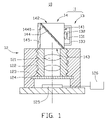
- FIG. 1 is a schematic, cross-sectional view of a fingerprint identification apparatus according to a first preferred embodiment
- FIGS. 2 and 3 are schematic, light path views of carrying out fingerprint identification by the fingerprint identification apparatus in FIG. 1 ;
- FIG. 4 is schematic, light path view of taking a picture by the fingerprint identification apparatus in FIG. 1 ;
- FIG. 5 is a schematic, cross-sectional view of a fingerprint identification apparatus according to a second preferred embodiment.
- FIG. 6 is a schematic, cross-sectional view of a portable electronic device including the fingerprint identification apparatus in FIG. 1 , according to a third preferred embodiment.
- the present fingerprint identification apparatus 10 includes an image pickup module 11 , and a digital camera module 12 .
- the image pickup module 11 includes a lighting module 13 and a beam splitter 14 placed on the opposite side of the lighting module 13 .
- the lighting module 13 includes a light source 131 and a collimating lens 132 disposed opposite to the light source 131 .
- the collimating lens 132 is used to transform light beams emitted from the light source 131 into parallel light.
- the light source 131 can be a semiconductor light emitting diode (LED), an organic light emitting diode (OLED), a combination of an edge-lighting type light guide plate with at least a LED, etc.
- the light source 131 is a semiconductor LED.
- the lighting module 13 can be provided without the collimating lens 132 when the light source 131 can directly emit the parallel light beams itself, for example, the light source 131 is a combination of an edge-lighting type light guide plate with at least one semiconductor LED, so that the light source 131 can be placed directly opposite to the beam splitter 14 .
- the lighting module 13 further includes a square shell 133 used to receive the light source 131 and the collimating lens 132 therein. Furthermore, a reflective film is suitably coated on inner surface of the shell 133 and configured for improving utilization ratio of the light emitted from the light source 131 .
- the beam splitter 14 includes an incident surface 141 , a first emitting surface 142 adjoining the incident surface 141 , a second emitting surface 143 opposite to the first emitting surface 142 , and a glass plate 144 obliquely located between the first emitting surface 142 and the second emitting surface 143 , a beam splitting film 1440 is coated on the glass plate 144 .
- the incident surface 141 is opposite to the lighting module 13 .
- the second emitting surface 143 is next to the digital camera module 12 and perpendicular to the incident surface 141 .
- the beam splitting film 1440 can be a dielectric optical film or a metallic film. In this embodiment, the beam splitting film 1440 is an aluminum film.
- the image pickup module 11 further includes a reflective film 145 .
- the reflective film 145 is coated on a surface of the beam splitter 14 that is opposite to the incident surface 141 .
- the digital camera module 12 includes several lenses 121 , a lens barrel 122 , a lens holder 123 , a glass plate 124 , an image sensor 125 and a fingerprint identification module 126 .
- the several lenses 121 are received in the lens barrel 122 .
- the lens barrel 122 is held in the lens holder 123 by engaging an internal thread of the lens holder 123 together with an external thread of the lens barrel 122 .
- the glass plate 124 is placed in the lens holder 123 and located between the lens 121 and the image sensor 125 , which is used to protect the image sensor 125 from contamination.
- the image sensor 125 is used to convert an optical signal into an electronic signal.
- the fingerprint identification module 126 is electrically connected with the image sensor 125 . There is a fingerprint information should be stored in advance in the fingerprint identification module 126 .
- parallel light beams 101 emitted from the lighting module 13 are incident into the beam splitter 14 by the incident surface 141 at a 45 degree angle advantageously, and then being separated into a first light beam 102 and a second light beam 103 with a same spectral component substantially, the first light beam 102 and the second light beam 103 are respectively incident into the reflective film 145 and the first emitting surface 142 .
- the second light beam 103 is again incident into the beam splitter 14 after being reflected by a finger 109 that placed on the first emitting surface 142 , and then separates into a third light beam 104 and a fourth light beam 105 with a same spectral component substantially by the beam splitting film 1440 .
- the third light beam 104 and the fourth light beam 105 are respectively incident into the digital camera module 12 and the lighting module 13 .
- the digital camera module 12 capture the fingerprint of the finger 109 , that is, the image sensor 125 of the digital camera module 12 receives the third light beam 104 passed through the several lens 121 , and converts the third light beam 104 into electronic signals correspondingly.
- the fingerprint identification module 126 then compares the electronic signals generated from the image sensor 125 with fingerprint information stored in advance to distinguish similarity between the captured image and a previously registered image so as to recognize the identification of the fingerprint.
- the first emitting surface 142 is provided in the direction facing towards the area where the image is to be taken, and the lighting module 13 is switched off.
- Light beams 106 reflected from the area is incident into the beam splitter 14 , and then separated into a third light beam 107 and a fourth light beam 108 with a same spectral component substantially by the beam splitting film 1440 .
- the third light beam 107 is incident into the digital camera module 12 after passing through the second emitting surface 143
- the fourth light beam 108 is incident into the lighting module 13 .
- the image sensor 125 of the digital camera module 12 receives the third light beam 107 passed through the several lenses 121 , and converts the third light beam 107 into electronic signals correspondingly.
- An image storage system (not shown) of the digital camera module 12 then saves the electronic signals therein, so as to realize the function for taking picture of the fingerprint identification apparatus 10 .
- the fingerprint identification apparatus 10 with simple structure is used for capturing and identifying fingerprint of the user with the assistance of the glass plate 144 with beam splitting film 1440 coating thereon, so that the fingerprint identification apparatus 10 can instantly identify the fingerprint of a user.
- the fingerprint identification apparatus 10 can also function as a camera for taking pictures.
- a fingerprint identification apparatus 20 in accordance with a second present embodiment, is shown.
- the fingerprint identification apparatus 20 is approximately same as that of the fingerprint identification apparatus 10 , the difference is the image pickup module.
- the fingerprint identification apparatus 20 includes an image pickup module 21 with a lighting source 23 for emitting parallel light beams and a beam splitter 24 disposed on the opposite side of the lighting source 23 .
- the beam splitter 24 includes a first triangular prism 241 and a second triangular prism 242 which adhered with the first triangular prism 241 .
- the first prism 241 and the second prism 242 together cooperatively formed an integral rectangular prism bisected by a junction of the triangular prisms.
- the integral rectangular prism formed by the first prism 241 and the second prism 242 includes a first input port 243 facing towards the area where the image is to be taken, a second input port 244 adjoining the lighting source 23 , and an output port 245 opposite to the first input port 243 .
- the first input port 243 is used to receive light beams in a first direction A from a fingerprint of a user or scenery.
- the second input port 244 could receive the light beams in a second direction B from the lighting source 23 when the lighting source 23 emitting the parallel light toward itself.
- the output port 245 is used to output the light beams along the first direction A from the first input port 243 to the digital camera module 12 .
- the first direction A is perpendicular to the second direction B.
- the portable electronic device 30 includes a main body 31 having a display screen 311 and a keystroke part 312 on a surface 301 thereof.
- the digital camera module 12 of the fingerprint identification apparatus 10 is located in the main body 31 and next to the display screen 311 .
- the image pickup module 11 is disposed on the main body 31 facing towards the lens barrel 122 of the digital camera module 12 . It can be understood that the keystroke part 312 can be placed on an adjacent surface of the surface 301 , instead.
- functions for fingerprint identification and image capturing of the portable electronic device 30 are approximately same as that of the fingerprint identification apparatus 10 .
- the functions of fingerprint identification and image capturing can be switched easily.
Landscapes
- Engineering & Computer Science (AREA)
- Physics & Mathematics (AREA)
- Optics & Photonics (AREA)
- Human Computer Interaction (AREA)
- General Physics & Mathematics (AREA)
- Multimedia (AREA)
- Theoretical Computer Science (AREA)
- Image Input (AREA)
- Measurement Of The Respiration, Hearing Ability, Form, And Blood Characteristics Of Living Organisms (AREA)
Abstract
A fingerprint identification apparatus includes an image pickup module and a digital camera module. The image pickup module including a beam splitter that includes a first surface, a second surface adjoining the first surface, a third surface opposite to the second surface; and a lighting module disposed facing towards the first surface and configured for emitting parallel light beams toward the first surface. The digital camera module is disposed facing towards the second surface and configured for capturing a fingerprint of a user or taking pictures; and a fingerprint identification module for distinguishing similarity between the captured fingerprint and a previously registered image.
Description
- 1. Technical Field
- The present invention generally relates to a fingerprint identification apparatus and a portable electronic device having same.
- 2. Description of Related Art
- With the trend toward a highly mobile workforce, the use of portable electronic devices such as mobile phone and personal digital assistant (PDA) are growing at an ever-increasing rate. These devices offer a variety of functions that are quickly becoming a necessity in people's daily life. A mobile phone usually has the function of storing personal information including communication records, contact information, daily events and so on. Consequently, a passcode is usually required for accessing and protecting personal information in a mobile phone. However, only several numbers are allowed for the passcode of mobile phones. The passcode can easily be deciphered, which makes personal information vulnerable. Therefore, a mobile phone having a fingerprint identification apparatus can achieve a high degree of safety for protection. The fingerprint identification apparatus in the mobile phone, for example, can verify that a user's fingerprints are in fact the fingerprints of its owner, and subsequently grant access to the functions and information therein.
- A conventional fingerprint identification apparatus of a mobile phone consists of two pieces of material, the first piece is transparent with adhesive on a side, the second piece has a side coated with a substance that would not adhere to the adhesive, this second piece is folded in the centre making two flaps, one flap having an opening with adhesive material provided on the outside. When the fingertip is placed on the adhesive surface of the first material, natural oils and dust are lifted from the finger leaving a clean and clear fingerprint on the adhesive. When the fold is closed, the non-adhering surface lies on the adhesive and protects the fingerprint until it had to be examined then the non-adhering surface on the flap lifts easily. Since, such fingerprint identification apparatus needs to collect a sample of the fingerprint and then to exam the sample, this result in that the operation is discommodious, especially that the fingerprint identification apparatus cannot identify the fingerprint of the user instantly, it is not an ideal fingerprint identification apparatus to be used in a portable electronic device.
- What is needed, is a fingerprint identification apparatus that can instantly identify the fingerprint of a user, thus making the fingerprint identification more convenient when used in a portable electronic device.
- A first present embodiment provides a fingerprint identification apparatus. The fingerprint identification apparatus includes: an image pickup module and a digital camera module. The image pickup module includes a beam splitter, a lighting module and a fingerprint identification module. The beam splitter includes a first surface, a second surface adjoining the first surface, a third surface opposite to the second surface. The lighting module is disposed facing towards the first surface and used to emit parallel light beams toward the first surface. The digital camera module is disposed facing towards the second surface, and being used to capture a fingerprint of a user or taking pictures. The fingerprint identification module is used to distinguish similarity between the captured fingerprint and a previously registered image.
- A second present embodiment provides a fingerprint identification apparatus. The fingerprint identification apparatus includes an image pickup module and a fingerprint identification module. The image pickup module comprising: a light source for emitting parallel light beams; a beam splitter having a first input port for receiving light beams in a first direction from a fingerprint of a user, a second input port for receiving the light beams in a second direction from the light source, and an output port for outputting the light beams along the first direction therefrom, the first direction being perpendicular to the second direction; a digital camera module for capturing an image of the fingerprint of a user or taking pictures. The fingerprint identification module is used to distinguish similarity between the captured fingerprint and a previously registered image.
- A third present embodiment provides portable electronic device, includes: a main body which has a display screen; and a fingerprint identification apparatus mounted on the main body. The fingerprint identification apparatus includes: an image pickup module, a digital camera module and a fingerprint identification module. The image pickup module includes a beam splitter and a lighting module. The beam splitter includes a first surface, a second surface adjoining the first surface, a third surface opposite to the second surface. The lighting module is disposed facing towards the first surface and used to emit parallel light beams toward the first surface. The digital camera module is disposed facing towards the second surface, and being used to capturing a fingerprint of a user or taking pictures. The fingerprint identification module is used to distinguish similarity between the captured fingerprint and a previously registered image.
- Other advantages and novel features will become more apparent from the following detailed description of preferred embodiments when taken in conjunction with the accompanying drawings.
- Many aspects of the present fingerprint identification apparatus and portable electronic device can be better understood with reference to the following drawings. The components in the drawings are not necessarily drawn to scale, the emphasis instead being placed upon clearly illustrating the principles of the present glue dispenser. Moreover, in the drawings, like reference numerals designate corresponding parts throughout the several views.
-
FIG. 1 is a schematic, cross-sectional view of a fingerprint identification apparatus according to a first preferred embodiment; -
FIGS. 2 and 3 are schematic, light path views of carrying out fingerprint identification by the fingerprint identification apparatus inFIG. 1 ; -
FIG. 4 is schematic, light path view of taking a picture by the fingerprint identification apparatus inFIG. 1 ; -
FIG. 5 is a schematic, cross-sectional view of a fingerprint identification apparatus according to a second preferred embodiment; and -
FIG. 6 is a schematic, cross-sectional view of a portable electronic device including the fingerprint identification apparatus inFIG. 1 , according to a third preferred embodiment. - The exemplifications set out herein illustrate various preferred embodiments, in various forms, and such exemplifications are not to be construed as limiting the scope of the present fingerprint identification apparatus and portable electronic device in any manner.
- Referring to
FIG. 1 , afingerprint identification apparatus 10, in accordance with a first present embodiment, is shown. The presentfingerprint identification apparatus 10 includes animage pickup module 11, and adigital camera module 12. - The
image pickup module 11 includes alighting module 13 and abeam splitter 14 placed on the opposite side of thelighting module 13. - The
lighting module 13 includes alight source 131 and acollimating lens 132 disposed opposite to thelight source 131. The collimatinglens 132 is used to transform light beams emitted from thelight source 131 into parallel light. Thelight source 131 can be a semiconductor light emitting diode (LED), an organic light emitting diode (OLED), a combination of an edge-lighting type light guide plate with at least a LED, etc. In this embodiment, thelight source 131 is a semiconductor LED. - It can be understood that the
lighting module 13 can be provided without the collimatinglens 132 when thelight source 131 can directly emit the parallel light beams itself, for example, thelight source 131 is a combination of an edge-lighting type light guide plate with at least one semiconductor LED, so that thelight source 131 can be placed directly opposite to thebeam splitter 14. - The
lighting module 13 further includes asquare shell 133 used to receive thelight source 131 and thecollimating lens 132 therein. Furthermore, a reflective film is suitably coated on inner surface of theshell 133 and configured for improving utilization ratio of the light emitted from thelight source 131. - The
beam splitter 14 includes anincident surface 141, afirst emitting surface 142 adjoining theincident surface 141, asecond emitting surface 143 opposite to thefirst emitting surface 142, and aglass plate 144 obliquely located between thefirst emitting surface 142 and the second emittingsurface 143, abeam splitting film 1440 is coated on theglass plate 144. Theincident surface 141 is opposite to thelighting module 13. Thesecond emitting surface 143 is next to thedigital camera module 12 and perpendicular to theincident surface 141. Thebeam splitting film 1440 can be a dielectric optical film or a metallic film. In this embodiment, the beam splittingfilm 1440 is an aluminum film. - The
image pickup module 11 further includes areflective film 145. Thereflective film 145 is coated on a surface of thebeam splitter 14 that is opposite to theincident surface 141. - The
digital camera module 12 includesseveral lenses 121, alens barrel 122, alens holder 123, aglass plate 124, animage sensor 125 and afingerprint identification module 126. Theseveral lenses 121 are received in thelens barrel 122. Thelens barrel 122 is held in thelens holder 123 by engaging an internal thread of thelens holder 123 together with an external thread of thelens barrel 122. Theglass plate 124 is placed in thelens holder 123 and located between thelens 121 and theimage sensor 125, which is used to protect theimage sensor 125 from contamination. Theimage sensor 125 is used to convert an optical signal into an electronic signal. Thefingerprint identification module 126 is electrically connected with theimage sensor 125. There is a fingerprint information should be stored in advance in thefingerprint identification module 126. - Referring to
FIG. 2 , parallellight beams 101 emitted from thelighting module 13 are incident into thebeam splitter 14 by theincident surface 141 at a 45 degree angle advantageously, and then being separated into afirst light beam 102 and a secondlight beam 103 with a same spectral component substantially, thefirst light beam 102 and the secondlight beam 103 are respectively incident into thereflective film 145 and the first emittingsurface 142. - Referring to
FIG. 3 , the secondlight beam 103 is again incident into thebeam splitter 14 after being reflected by afinger 109 that placed on the first emittingsurface 142, and then separates into a thirdlight beam 104 and a fourthlight beam 105 with a same spectral component substantially by thebeam splitting film 1440. The thirdlight beam 104 and the fourthlight beam 105 are respectively incident into thedigital camera module 12 and thelighting module 13. Thedigital camera module 12 capture the fingerprint of thefinger 109, that is, theimage sensor 125 of thedigital camera module 12 receives the thirdlight beam 104 passed through theseveral lens 121, and converts the thirdlight beam 104 into electronic signals correspondingly. Thefingerprint identification module 126 then compares the electronic signals generated from theimage sensor 125 with fingerprint information stored in advance to distinguish similarity between the captured image and a previously registered image so as to recognize the identification of the fingerprint. - Referring to
FIG. 4 , when taking pictures with the presentfingerprint identification apparatus 10, the first emittingsurface 142 is provided in the direction facing towards the area where the image is to be taken, and thelighting module 13 is switched off.Light beams 106 reflected from the area is incident into thebeam splitter 14, and then separated into a thirdlight beam 107 and a fourthlight beam 108 with a same spectral component substantially by thebeam splitting film 1440. The thirdlight beam 107 is incident into thedigital camera module 12 after passing through the second emittingsurface 143, and the fourthlight beam 108 is incident into thelighting module 13. Theimage sensor 125 of thedigital camera module 12 receives the thirdlight beam 107 passed through theseveral lenses 121, and converts the thirdlight beam 107 into electronic signals correspondingly. An image storage system (not shown) of thedigital camera module 12 then saves the electronic signals therein, so as to realize the function for taking picture of thefingerprint identification apparatus 10. - As described above, the
fingerprint identification apparatus 10 with simple structure is used for capturing and identifying fingerprint of the user with the assistance of theglass plate 144 withbeam splitting film 1440 coating thereon, so that thefingerprint identification apparatus 10 can instantly identify the fingerprint of a user. In addition, thefingerprint identification apparatus 10 can also function as a camera for taking pictures. - Referring to
FIG. 5 , afingerprint identification apparatus 20, in accordance with a second present embodiment, is shown. Thefingerprint identification apparatus 20 is approximately same as that of thefingerprint identification apparatus 10, the difference is the image pickup module. - The
fingerprint identification apparatus 20 includes animage pickup module 21 with alighting source 23 for emitting parallel light beams and abeam splitter 24 disposed on the opposite side of thelighting source 23. Thebeam splitter 24 includes a firsttriangular prism 241 and a secondtriangular prism 242 which adhered with the firsttriangular prism 241. Thefirst prism 241 and thesecond prism 242 together cooperatively formed an integral rectangular prism bisected by a junction of the triangular prisms. - The integral rectangular prism formed by the
first prism 241 and thesecond prism 242 includes afirst input port 243 facing towards the area where the image is to be taken, asecond input port 244 adjoining thelighting source 23, and anoutput port 245 opposite to thefirst input port 243. Thefirst input port 243 is used to receive light beams in a first direction A from a fingerprint of a user or scenery. Thesecond input port 244 could receive the light beams in a second direction B from thelighting source 23 when thelighting source 23 emitting the parallel light toward itself. Theoutput port 245 is used to output the light beams along the first direction A from thefirst input port 243 to thedigital camera module 12. In this embodiment, the first direction A is perpendicular to the second direction B. - The
fingerprint identification apparatus 20 can also capture fingerprint information accurately by using the integral rectangular prism formed by thefirst prism 241 and thesecond prism 242. In addition, thefingerprint identification apparatus 20 can also be used for taking pictures. - Referring to
FIG. 6 , a portableelectronic device 30 including thefingerprint identification apparatus 10 described above, in accordance with a third present embodiment, is shown. The portableelectronic device 30 includes amain body 31 having adisplay screen 311 and akeystroke part 312 on asurface 301 thereof. Thedigital camera module 12 of thefingerprint identification apparatus 10 is located in themain body 31 and next to thedisplay screen 311. Theimage pickup module 11 is disposed on themain body 31 facing towards thelens barrel 122 of thedigital camera module 12. It can be understood that thekeystroke part 312 can be placed on an adjacent surface of thesurface 301, instead. - In this embodiment, functions for fingerprint identification and image capturing of the portable
electronic device 30 are approximately same as that of thefingerprint identification apparatus 10. When the portableelectronic device 30 is in operation, the functions of fingerprint identification and image capturing can be switched easily. - It is to be understood, however, that even though numerous characteristics and advantages of the present invention have been set forth in the foregoing description, together with details of the structure and function of the invention, the disclosure is illustrative only, and changes may be made in detail, especially in matters of shape, size, and arrangement of parts within the principles of the invention to the full extent indicated by the broad general meaning of the terms in which the appended claims are expressed.
Claims (12)
1. A fingerprint identification apparatus comprising:
an image pickup module comprising:
a beam splitter including a first surface, a second surface adjoining the first surface, a third surface opposite to the second surface; and
a lighting module disposed facing towards the first surface and configured for emitting parallel light beams toward the first surface; and
a digital camera module disposed facing towards the second surface, the digital camera module being configured for capturing a fingerprint of a user or taking pictures; and
a fingerprint identification module for distinguishing similarity between the captured fingerprint and a previously registered image.
2. The fingerprint identification apparatus of claim 1 , wherein the lighting module comprises a light source and a collimating lens, the collimating lens being disposed between the light source and the first surface of the beam splitter.
3. The fingerprint identification apparatus of claim 2 , wherein the light source is selected from a group consisting of a semiconductor light emitting diode, and an organic light emitting diode.
4. The fingerprint identification apparatus of claim 1 , further comprising a reflective film coated on a surface of the beam splitter that is opposite to the first surface.
5. The fingerprint identification apparatus of claim 1 , wherein the beam splitter further includes a glass plate with a beam splitting film coating thereon, the parallel light beams incidence at a 45 degree angle.
6. The fingerprint identification apparatus of claim 5 , wherein the beam splitting film is selected from a group consisting of a dielectric optical film and a metallic film.
7. A fingerprint identification apparatus comprising:
an image pickup module comprising:
a light source for emitting parallel light beams;
a beam splitter having a first input port for receiving light beams in a first direction from a fingerprint of a user, a second input port for receiving the light beams in a second direction from the light source, and an output port for outputting the light beams along the first direction therefrom, the first direction being perpendicular to the second direction;
a digital camera module for capturing an image of the fingerprint of a user or taking pictures; and
a fingerprint identification module for distinguishing similarity between the captured fingerprint and a previously registered image.
8. The fingerprint identification apparatus of claim 7 , wherein the beam splitter includes first and second triangular prisms adhered to each other, the first and second prisms cooperatively forming an integral rectangular prism bisected by a junction of the triangular prisms.
9. A portable electronic device comprising
a main body having a display screen; and
a fingerprint identification apparatus mounted on the main body, the fingerprint identification apparatus comprising:
an image pickup module comprising:
a beam splitter including a first surface, a second surface adjoining the first surface, a third surface opposite to the second surface; and
a lighting module disposed facing towards the first surface and configured for emitting parallel light beams toward the first surface; and
a digital camera module disposed facing towards the second surface, the digital camera module configured for capturing a fingerprint of a user or taking pictures; and
a fingerprint identification module for distinguishing similarity between the captured fingerprint and a previously registered image.
10. The portable electronic device of claim 9 , wherein the fingerprint identification apparatus further comprises a reflective film coated on a surface of the beam splitter that is opposite to the first surface.
11. The portable electronic device of claim 9 , wherein the beam splitter further includes a glass plate with a beam splitting film coating thereon, the parallel light beams incidence at a 45 degree angle.
12. The portable electronic device of claim 11 , wherein the beam splitting film is selected from a group consisting of a dielectric optical film and a metallic film.
Applications Claiming Priority (2)
| Application Number | Priority Date | Filing Date | Title |
|---|---|---|---|
| CN200710200505.2 | 2007-04-25 | ||
| CNA2007102005052A CN101295350A (en) | 2007-04-25 | 2007-04-25 | Fingerprint identification device and portable electronic device |
Publications (1)
| Publication Number | Publication Date |
|---|---|
| US20080267463A1 true US20080267463A1 (en) | 2008-10-30 |
Family
ID=39887023
Family Applications (1)
| Application Number | Title | Priority Date | Filing Date |
|---|---|---|---|
| US11/923,040 Abandoned US20080267463A1 (en) | 2007-04-25 | 2007-10-24 | Fingerprint identification apparatus and portable electronic device having same |
Country Status (2)
| Country | Link |
|---|---|
| US (1) | US20080267463A1 (en) |
| CN (1) | CN101295350A (en) |
Cited By (9)
| Publication number | Priority date | Publication date | Assignee | Title |
|---|---|---|---|---|
| US20100208952A1 (en) * | 2009-02-19 | 2010-08-19 | Jew-Chieh Wu | Fingerprint indentifying system |
| CN103336958A (en) * | 2013-07-22 | 2013-10-02 | 屈帅 | Handprint identifying anti-theft device for electronic product border |
| WO2017142500A1 (en) * | 2016-02-21 | 2017-08-24 | Gri̇med Sağlik Hi̇zmetleri̇ Ve Bi̇lgi̇sayar Ürünleri̇ Sanayi̇ Ti̇caret Li̇mi̇ted Şi̇rketi̇ | Portable non-contact multispectral fingerprint and / or palm print imaging device |
| US20180348438A1 (en) * | 2015-11-25 | 2018-12-06 | Zte Corporation | Terminal Having Fingerprint Identification Function |
| US10489629B1 (en) | 2018-02-06 | 2019-11-26 | Shenzhen GOODIX Technology Co., Ltd. | Under-screen biometric identification apparatus and electronic device |
| WO2019235039A1 (en) * | 2018-06-05 | 2019-12-12 | ソニー株式会社 | Optical module, authentication device, control method, and program |
| EP3591578A1 (en) * | 2018-07-06 | 2020-01-08 | Shenzhen Goodix Technology Co., Ltd. | Under-screen biometric identification apparatus and electronic device |
| US20200342197A1 (en) * | 2019-04-25 | 2020-10-29 | Shenzhen GOODIX Technology Co., Ltd. | Optical fingerprint identification apparatus, electronic device and fingerprint identification method |
| US20220224618A1 (en) * | 2021-01-12 | 2022-07-14 | Dell Products L.P. | Transceiver with integrated visual indicator for port link and activity |
Families Citing this family (10)
| Publication number | Priority date | Publication date | Assignee | Title |
|---|---|---|---|---|
| CN105184247B (en) * | 2015-08-28 | 2018-12-28 | 京东方科技集团股份有限公司 | A kind of fingerprint recognition element, its recognition methods, display device and display device |
| CN105303177B (en) * | 2015-10-21 | 2019-02-01 | Oppo广东移动通信有限公司 | A kind of camera with fingerprint identification function and corresponding terminal |
| CN105469030B (en) * | 2015-11-11 | 2020-06-19 | 西安易朴通讯技术有限公司 | Electronic equipment with fingerprint identification function |
| CN106355160A (en) * | 2016-09-06 | 2017-01-25 | 京东方科技集团股份有限公司 | Pattern recognition device and electronic equipment |
| CN108241832A (en) * | 2016-12-23 | 2018-07-03 | 创智能科技股份有限公司 | Biometric identification device |
| CN108009533A (en) * | 2018-01-04 | 2018-05-08 | 敦捷光电股份有限公司 | Optical fingerprint identification system |
| CN109190583B (en) * | 2018-09-18 | 2020-11-03 | 维沃移动通信有限公司 | a terminal device |
| WO2020088129A1 (en) * | 2018-10-30 | 2020-05-07 | Oppo广东移动通信有限公司 | Fingerprint module, electronic device and fingerprint acquisition method |
| CN109376668B (en) * | 2018-10-30 | 2024-02-27 | Oppo广东移动通信有限公司 | Fingerprint module, electronic equipment and fingerprint acquisition method |
| CN113627344B (en) * | 2021-08-11 | 2025-02-25 | 上海乐闪闪智能科技有限公司 | Dual biometric detection system, secure identification method, application and electronic device |
Citations (9)
| Publication number | Priority date | Publication date | Assignee | Title |
|---|---|---|---|---|
| US3771129A (en) * | 1972-07-27 | 1973-11-06 | Sperry Rand Corp | Optical processor fingerprint identification apparatus |
| US5448649A (en) * | 1994-05-24 | 1995-09-05 | Chen; Wang S. | Apparatus for imaging fingerprint or topographic relief pattern on the surface of an object |
| US5812252A (en) * | 1995-01-31 | 1998-09-22 | Arete Associates | Fingerprint--Acquisition apparatus for access control; personal weapon and other systems controlled thereby |
| US6426837B1 (en) * | 1999-03-22 | 2002-07-30 | Mems Optical, Inc. | Diffractive selectively polarizing beam splitter and beam routing prisms produced thereby |
| US6631199B1 (en) * | 1998-12-08 | 2003-10-07 | Allen W. L. Topping | Automated identification through analysis of optical birefringence within nail beds |
| US6753989B2 (en) * | 2001-08-02 | 2004-06-22 | De La Rue International Limited | Recording surface relief microstructure |
| US20070058844A1 (en) * | 2005-09-06 | 2007-03-15 | Fenrich Richard K | System and method for implementing algorithmic correction of image distortion within a fingerprint imaging system |
| US20070165208A1 (en) * | 2005-12-23 | 2007-07-19 | Ingenia Technology Limited | Optical authentication |
| US20080118114A1 (en) * | 2002-05-09 | 2008-05-22 | Sony Corporation | Living-tissue pattern detecting method, living-tissue pattern detecting device, biometric authentication method, and biometric authentication device |
-
2007
- 2007-04-25 CN CNA2007102005052A patent/CN101295350A/en active Pending
- 2007-10-24 US US11/923,040 patent/US20080267463A1/en not_active Abandoned
Patent Citations (10)
| Publication number | Priority date | Publication date | Assignee | Title |
|---|---|---|---|---|
| US3771129A (en) * | 1972-07-27 | 1973-11-06 | Sperry Rand Corp | Optical processor fingerprint identification apparatus |
| US5448649A (en) * | 1994-05-24 | 1995-09-05 | Chen; Wang S. | Apparatus for imaging fingerprint or topographic relief pattern on the surface of an object |
| US5812252A (en) * | 1995-01-31 | 1998-09-22 | Arete Associates | Fingerprint--Acquisition apparatus for access control; personal weapon and other systems controlled thereby |
| US6631199B1 (en) * | 1998-12-08 | 2003-10-07 | Allen W. L. Topping | Automated identification through analysis of optical birefringence within nail beds |
| US6426837B1 (en) * | 1999-03-22 | 2002-07-30 | Mems Optical, Inc. | Diffractive selectively polarizing beam splitter and beam routing prisms produced thereby |
| US6753989B2 (en) * | 2001-08-02 | 2004-06-22 | De La Rue International Limited | Recording surface relief microstructure |
| US20080118114A1 (en) * | 2002-05-09 | 2008-05-22 | Sony Corporation | Living-tissue pattern detecting method, living-tissue pattern detecting device, biometric authentication method, and biometric authentication device |
| US7415139B2 (en) * | 2002-05-09 | 2008-08-19 | Sony Corporation | Living-tissue pattern detecting method, living-tissue pattern detecting device, biometric authentication method, and biometric authentication device |
| US20070058844A1 (en) * | 2005-09-06 | 2007-03-15 | Fenrich Richard K | System and method for implementing algorithmic correction of image distortion within a fingerprint imaging system |
| US20070165208A1 (en) * | 2005-12-23 | 2007-07-19 | Ingenia Technology Limited | Optical authentication |
Cited By (15)
| Publication number | Priority date | Publication date | Assignee | Title |
|---|---|---|---|---|
| US8391569B2 (en) * | 2009-02-19 | 2013-03-05 | Gingy Technology Inc. | Fingerprint identifying system |
| US20100208952A1 (en) * | 2009-02-19 | 2010-08-19 | Jew-Chieh Wu | Fingerprint indentifying system |
| CN103336958A (en) * | 2013-07-22 | 2013-10-02 | 屈帅 | Handprint identifying anti-theft device for electronic product border |
| US10656340B2 (en) * | 2015-11-25 | 2020-05-19 | Zte Corporation | Terminal having fingerprint identification function |
| US20180348438A1 (en) * | 2015-11-25 | 2018-12-06 | Zte Corporation | Terminal Having Fingerprint Identification Function |
| WO2017142500A1 (en) * | 2016-02-21 | 2017-08-24 | Gri̇med Sağlik Hi̇zmetleri̇ Ve Bi̇lgi̇sayar Ürünleri̇ Sanayi̇ Ti̇caret Li̇mi̇ted Şi̇rketi̇ | Portable non-contact multispectral fingerprint and / or palm print imaging device |
| US10691917B2 (en) | 2018-02-06 | 2020-06-23 | Shenzhen GOODIX Technology Co., Ltd. | Under-screen biometric identification apparatus and electronic device |
| US10489629B1 (en) | 2018-02-06 | 2019-11-26 | Shenzhen GOODIX Technology Co., Ltd. | Under-screen biometric identification apparatus and electronic device |
| CN111767893A (en) * | 2018-02-06 | 2020-10-13 | 深圳市汇顶科技股份有限公司 | Under-screen biometric identification devices and electronic equipment |
| US11501555B2 (en) | 2018-02-06 | 2022-11-15 | Shenzhen GOODIX Technology Co., Ltd. | Under-screen biometric identification apparatus and electronic device |
| WO2019235039A1 (en) * | 2018-06-05 | 2019-12-12 | ソニー株式会社 | Optical module, authentication device, control method, and program |
| EP3591578A1 (en) * | 2018-07-06 | 2020-01-08 | Shenzhen Goodix Technology Co., Ltd. | Under-screen biometric identification apparatus and electronic device |
| US20200342197A1 (en) * | 2019-04-25 | 2020-10-29 | Shenzhen GOODIX Technology Co., Ltd. | Optical fingerprint identification apparatus, electronic device and fingerprint identification method |
| US11810395B2 (en) * | 2019-04-25 | 2023-11-07 | Shenzhen GOODIX Technology Co., Ltd. | Optical fingerprint identification apparatus, electronic device and fingerprint identification method |
| US20220224618A1 (en) * | 2021-01-12 | 2022-07-14 | Dell Products L.P. | Transceiver with integrated visual indicator for port link and activity |
Also Published As
| Publication number | Publication date |
|---|---|
| CN101295350A (en) | 2008-10-29 |
Similar Documents
| Publication | Publication Date | Title |
|---|---|---|
| US8270686B2 (en) | Fingerprint identification apparatus and portable electronic device having same | |
| US11386691B2 (en) | Optical device, module, apparatus, and system for fingerprint identification | |
| CN110235143B (en) | Under-screen fingerprint recognition device and electronic equipment | |
| EP3825901B1 (en) | Lens system, fingerprint identification device and terminal device | |
| US8204283B2 (en) | Fingerprint input module | |
| US11366290B2 (en) | Lens system, fingerprint identification apparatus and terminal device | |
| CN101295350A (en) | Fingerprint identification device and portable electronic device | |
| CN108108718A (en) | Thin film transistor panel for optical fingerprint identification in screen | |
| WO2019237872A1 (en) | Fingerprint identification apparatus and electronic device | |
| CN109784264B (en) | Optical fingerprint imaging device and display | |
| WO2017118031A1 (en) | Optical fingerprint sensor module | |
| CN108564023A (en) | Fingerprint identification device and display equipment | |
| WO2020243934A1 (en) | Optical image acquisition apparatus and electronic device | |
| KR20180068040A (en) | Flat Panel Display Embedding Optical Imaging Sensor | |
| CN209312028U (en) | Optical lens, fingerprint recognition mould group and mobile terminal | |
| US8593560B2 (en) | Image-capturing module for simplifying optical component | |
| CN106264448B (en) | Skin analysis device and image acquisition module thereof | |
| CN111133442A (en) | Fingerprint detection device and electronic equipment | |
| CN210142338U (en) | Optical fingerprint identification module and electronic equipment | |
| CN210295124U (en) | Fingerprint detection device and electronic equipment | |
| CN109271058B (en) | Display module and electronic device | |
| EP3591578B1 (en) | Under-screen biometric identification apparatus and electronic device | |
| WO2019134062A1 (en) | Light-emitting diode panel for in-screen optical fingerprint recognition | |
| TWI402759B (en) | Fingerprint recognizing device and portable electronic device | |
| US20200285827A1 (en) | Under-display sensing device |
Legal Events
| Date | Code | Title | Description |
|---|---|---|---|
| AS | Assignment |
Owner name: HON HAI PRECISION INDUSTRY CO., LTD., TAIWAN Free format text: ASSIGNMENT OF ASSIGNORS INTEREST;ASSIGNOR:YUAN, KUN-I;REEL/FRAME:020006/0988 Effective date: 20071019 |
|
| STCB | Information on status: application discontinuation |
Free format text: ABANDONED -- FAILURE TO RESPOND TO AN OFFICE ACTION |