US20080098983A1 - Cool combustion emissions solution for auto-igniting internal combustion engine - Google Patents
Cool combustion emissions solution for auto-igniting internal combustion engine Download PDFInfo
- Publication number
- US20080098983A1 US20080098983A1 US11/588,015 US58801506A US2008098983A1 US 20080098983 A1 US20080098983 A1 US 20080098983A1 US 58801506 A US58801506 A US 58801506A US 2008098983 A1 US2008098983 A1 US 2008098983A1
- Authority
- US
- United States
- Prior art keywords
- fuel
- volume
- engine
- piston
- internal combustion
- Prior art date
- Legal status (The legal status is an assumption and is not a legal conclusion. Google has not performed a legal analysis and makes no representation as to the accuracy of the status listed.)
- Abandoned
Links
- 238000002485 combustion reaction Methods 0.000 title claims abstract description 55
- 239000000446 fuel Substances 0.000 claims abstract description 99
- 238000004519 manufacturing process Methods 0.000 claims abstract description 10
- 239000004071 soot Substances 0.000 claims abstract 3
- 238000002347 injection Methods 0.000 claims description 17
- 239000007924 injection Substances 0.000 claims description 17
- 238000000034 method Methods 0.000 claims description 16
- 239000012530 fluid Substances 0.000 claims description 5
- 239000007921 spray Substances 0.000 claims description 5
- 239000007788 liquid Substances 0.000 claims description 4
- 230000004044 response Effects 0.000 claims description 2
- 230000005465 channeling Effects 0.000 claims 1
- 230000015572 biosynthetic process Effects 0.000 abstract description 2
- GQPLMRYTRLFLPF-UHFFFAOYSA-N Nitrous Oxide Chemical compound [O-][N+]#N GQPLMRYTRLFLPF-UHFFFAOYSA-N 0.000 description 22
- 230000006835 compression Effects 0.000 description 17
- 238000007906 compression Methods 0.000 description 17
- 239000001272 nitrous oxide Substances 0.000 description 11
- 239000013618 particulate matter Substances 0.000 description 5
- 239000000203 mixture Substances 0.000 description 4
- 239000002283 diesel fuel Substances 0.000 description 3
- 238000006073 displacement reaction Methods 0.000 description 3
- 238000013459 approach Methods 0.000 description 2
- 230000008901 benefit Effects 0.000 description 2
- 238000004891 communication Methods 0.000 description 2
- 239000007789 gas Substances 0.000 description 2
- 229930195733 hydrocarbon Natural products 0.000 description 2
- 150000002430 hydrocarbons Chemical class 0.000 description 2
- -1 but not limited to Substances 0.000 description 1
- 239000006227 byproduct Substances 0.000 description 1
- 239000003818 cinder Substances 0.000 description 1
- 239000000567 combustion gas Substances 0.000 description 1
- 238000009826 distribution Methods 0.000 description 1
- 230000008030 elimination Effects 0.000 description 1
- 238000003379 elimination reaction Methods 0.000 description 1
- 238000005516 engineering process Methods 0.000 description 1
- 239000003502 gasoline Substances 0.000 description 1
- 239000010763 heavy fuel oil Substances 0.000 description 1
- 230000003993 interaction Effects 0.000 description 1
- 238000012986 modification Methods 0.000 description 1
- 230000004048 modification Effects 0.000 description 1
- 239000002245 particle Substances 0.000 description 1
- 230000008569 process Effects 0.000 description 1
- 238000010791 quenching Methods 0.000 description 1
- 230000000171 quenching effect Effects 0.000 description 1
- 230000009467 reduction Effects 0.000 description 1
- 238000007493 shaping process Methods 0.000 description 1
- 239000000243 solution Substances 0.000 description 1
- 208000024891 symptom Diseases 0.000 description 1
- 238000012546 transfer Methods 0.000 description 1
Images

Classifications
-
- F—MECHANICAL ENGINEERING; LIGHTING; HEATING; WEAPONS; BLASTING
- F02—COMBUSTION ENGINES; HOT-GAS OR COMBUSTION-PRODUCT ENGINE PLANTS
- F02B—INTERNAL-COMBUSTION PISTON ENGINES; COMBUSTION ENGINES IN GENERAL
- F02B23/00—Other engines characterised by special shape or construction of combustion chambers to improve operation
- F02B23/02—Other engines characterised by special shape or construction of combustion chambers to improve operation with compression ignition
- F02B23/06—Other engines characterised by special shape or construction of combustion chambers to improve operation with compression ignition the combustion space being arranged in working piston
- F02B23/0618—Other engines characterised by special shape or construction of combustion chambers to improve operation with compression ignition the combustion space being arranged in working piston having in-cylinder means to influence the charge motion
- F02B23/063—Other engines characterised by special shape or construction of combustion chambers to improve operation with compression ignition the combustion space being arranged in working piston having in-cylinder means to influence the charge motion the combustion space in the piston interacting fluid dynamically with the cylinder head, the injector body or the cylinder wall
-
- F—MECHANICAL ENGINEERING; LIGHTING; HEATING; WEAPONS; BLASTING
- F02—COMBUSTION ENGINES; HOT-GAS OR COMBUSTION-PRODUCT ENGINE PLANTS
- F02B—INTERNAL-COMBUSTION PISTON ENGINES; COMBUSTION ENGINES IN GENERAL
- F02B1/00—Engines characterised by fuel-air mixture compression
- F02B1/12—Engines characterised by fuel-air mixture compression with compression ignition
-
- F—MECHANICAL ENGINEERING; LIGHTING; HEATING; WEAPONS; BLASTING
- F02—COMBUSTION ENGINES; HOT-GAS OR COMBUSTION-PRODUCT ENGINE PLANTS
- F02B—INTERNAL-COMBUSTION PISTON ENGINES; COMBUSTION ENGINES IN GENERAL
- F02B23/00—Other engines characterised by special shape or construction of combustion chambers to improve operation
- F02B23/02—Other engines characterised by special shape or construction of combustion chambers to improve operation with compression ignition
- F02B23/06—Other engines characterised by special shape or construction of combustion chambers to improve operation with compression ignition the combustion space being arranged in working piston
- F02B23/0633—Other engines characterised by special shape or construction of combustion chambers to improve operation with compression ignition the combustion space being arranged in working piston the combustion space being almost completely enclosed in the piston, i.e. having a small inlet in comparison to its volume
-
- F—MECHANICAL ENGINEERING; LIGHTING; HEATING; WEAPONS; BLASTING
- F02—COMBUSTION ENGINES; HOT-GAS OR COMBUSTION-PRODUCT ENGINE PLANTS
- F02B—INTERNAL-COMBUSTION PISTON ENGINES; COMBUSTION ENGINES IN GENERAL
- F02B23/00—Other engines characterised by special shape or construction of combustion chambers to improve operation
- F02B23/02—Other engines characterised by special shape or construction of combustion chambers to improve operation with compression ignition
- F02B23/06—Other engines characterised by special shape or construction of combustion chambers to improve operation with compression ignition the combustion space being arranged in working piston
- F02B23/0636—Other engines characterised by special shape or construction of combustion chambers to improve operation with compression ignition the combustion space being arranged in working piston the combustion space having a substantially flat and horizontal bottom
- F02B23/0639—Other engines characterised by special shape or construction of combustion chambers to improve operation with compression ignition the combustion space being arranged in working piston the combustion space having a substantially flat and horizontal bottom the combustion space having substantially the shape of a cylinder
-
- F—MECHANICAL ENGINEERING; LIGHTING; HEATING; WEAPONS; BLASTING
- F02—COMBUSTION ENGINES; HOT-GAS OR COMBUSTION-PRODUCT ENGINE PLANTS
- F02B—INTERNAL-COMBUSTION PISTON ENGINES; COMBUSTION ENGINES IN GENERAL
- F02B23/00—Other engines characterised by special shape or construction of combustion chambers to improve operation
- F02B23/02—Other engines characterised by special shape or construction of combustion chambers to improve operation with compression ignition
- F02B23/06—Other engines characterised by special shape or construction of combustion chambers to improve operation with compression ignition the combustion space being arranged in working piston
- F02B23/0645—Details related to the fuel injector or the fuel spray
- F02B23/0648—Means or methods to improve the spray dispersion, evaporation or ignition
- F02B23/0651—Means or methods to improve the spray dispersion, evaporation or ignition the fuel spray impinging on reflecting surfaces or being specially guided throughout the combustion space
-
- F—MECHANICAL ENGINEERING; LIGHTING; HEATING; WEAPONS; BLASTING
- F02—COMBUSTION ENGINES; HOT-GAS OR COMBUSTION-PRODUCT ENGINE PLANTS
- F02M—SUPPLYING COMBUSTION ENGINES IN GENERAL WITH COMBUSTIBLE MIXTURES OR CONSTITUENTS THEREOF
- F02M67/00—Apparatus in which fuel-injection is effected by means of high-pressure gas, the gas carrying the fuel into working cylinders of the engine, e.g. air-injection type
- F02M67/02—Apparatus in which fuel-injection is effected by means of high-pressure gas, the gas carrying the fuel into working cylinders of the engine, e.g. air-injection type the gas being compressed air, e.g. compressed in pumps
- F02M67/04—Apparatus in which fuel-injection is effected by means of high-pressure gas, the gas carrying the fuel into working cylinders of the engine, e.g. air-injection type the gas being compressed air, e.g. compressed in pumps the air being extracted from working cylinders of the engine
-
- F—MECHANICAL ENGINEERING; LIGHTING; HEATING; WEAPONS; BLASTING
- F02—COMBUSTION ENGINES; HOT-GAS OR COMBUSTION-PRODUCT ENGINE PLANTS
- F02M—SUPPLYING COMBUSTION ENGINES IN GENERAL WITH COMBUSTIBLE MIXTURES OR CONSTITUENTS THEREOF
- F02M67/00—Apparatus in which fuel-injection is effected by means of high-pressure gas, the gas carrying the fuel into working cylinders of the engine, e.g. air-injection type
- F02M67/10—Injectors peculiar thereto, e.g. valve less type
- F02M67/12—Injectors peculiar thereto, e.g. valve less type having valves
-
- F—MECHANICAL ENGINEERING; LIGHTING; HEATING; WEAPONS; BLASTING
- F02—COMBUSTION ENGINES; HOT-GAS OR COMBUSTION-PRODUCT ENGINE PLANTS
- F02B—INTERNAL-COMBUSTION PISTON ENGINES; COMBUSTION ENGINES IN GENERAL
- F02B2275/00—Other engines, components or details, not provided for in other groups of this subclass
- F02B2275/14—Direct injection into combustion chamber
-
- F—MECHANICAL ENGINEERING; LIGHTING; HEATING; WEAPONS; BLASTING
- F02—COMBUSTION ENGINES; HOT-GAS OR COMBUSTION-PRODUCT ENGINE PLANTS
- F02B—INTERNAL-COMBUSTION PISTON ENGINES; COMBUSTION ENGINES IN GENERAL
- F02B3/00—Engines characterised by air compression and subsequent fuel addition
- F02B3/06—Engines characterised by air compression and subsequent fuel addition with compression ignition
-
- F—MECHANICAL ENGINEERING; LIGHTING; HEATING; WEAPONS; BLASTING
- F02—COMBUSTION ENGINES; HOT-GAS OR COMBUSTION-PRODUCT ENGINE PLANTS
- F02D—CONTROLLING COMBUSTION ENGINES
- F02D13/00—Controlling the engine output power by varying inlet or exhaust valve operating characteristics, e.g. timing
- F02D13/02—Controlling the engine output power by varying inlet or exhaust valve operating characteristics, e.g. timing during engine operation
- F02D13/0269—Controlling the valves to perform a Miller-Atkinson cycle
-
- Y—GENERAL TAGGING OF NEW TECHNOLOGICAL DEVELOPMENTS; GENERAL TAGGING OF CROSS-SECTIONAL TECHNOLOGIES SPANNING OVER SEVERAL SECTIONS OF THE IPC; TECHNICAL SUBJECTS COVERED BY FORMER USPC CROSS-REFERENCE ART COLLECTIONS [XRACs] AND DIGESTS
- Y02—TECHNOLOGIES OR APPLICATIONS FOR MITIGATION OR ADAPTATION AGAINST CLIMATE CHANGE
- Y02T—CLIMATE CHANGE MITIGATION TECHNOLOGIES RELATED TO TRANSPORTATION
- Y02T10/00—Road transport of goods or passengers
- Y02T10/10—Internal combustion engine [ICE] based vehicles
- Y02T10/12—Improving ICE efficiencies
Definitions
- the present disclosure relates generally to low emissions cool combustion in an internal combustion engine, and relates more particularly to a structure and method of injecting fuel into a compressed air stream in a variable volume of an internal combustion engine.
- NOx nitrous oxide
- unburned hydrocarbons are generally believed to be the result of inadequate air being available in the vicinity of the fuel during combustion while temperature and pressure remain above an auto-ignition point.
- HCCI homogeneous charge compression ignition
- the present disclosure is directed to these and other problems associated with undesirable emissions from compression ignition engines.
- a method of operating an internal combustion engine includes compressing a trapped quantity of air in a variable volume beyond an auto-ignition point of a fuel. A majority of the compressed trapped quantity of air is displaced from a first volume to a second volume of the variable volume by moving an engine piston from top dead center. The displacement includes flowing the compressed air away from an engine head and through an airflow passage of the variable volume, which is defined by a surface other than an engine block. Fuel is injected into the compressed air flowing through the airflow passage. The fuel is then auto-ignited.
- an internal combustion engine in another aspect, includes a variable volume with portions defined by an engine head, an engine block and a reciprocating piston.
- the engine includes means for trapping a quantity of air in the variable volume when the piston moves toward top dead center.
- the variable volume includes an airflow passage that is defined by a surface other than the block, and the variable volume includes a first volume fluidly connected to a second volume by the airflow passage when the piston is at top dead center. Movement of the piston from top dead center displaces fluid in the first volume through the airflow passage, away from the head, to the second volume.
- a fuel injector is positioned for injection of fuel into the airflow passage.
- the engine also includes means for actuating the fuel injector to inject fuel when air in the variable volume is above an auto-ignition point of the fuel.
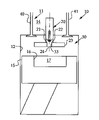
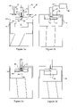
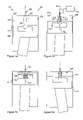
- FIGS. 1 a - d are a sequence of events in an internal combustion engine according to one embodiment of the present disclosure
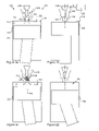
- FIGS. 2 a - d are a sequence of events in an internal combustion engine according to a second embodiment of the present disclosure
- FIGS. 3 a - d are a sequence of events in an internal combustion engine according to a third embodiment of the present disclosure.
- FIG. 4 is a graph of equivalence ratio ⁇ versus combustion temperature T, that identifies particle matter production and NOx production regimes.
- Engines 10 , 110 , 210 each include an engine body 11 , 111 , 211 that comprises an engine head 14 , 114 , 214 and a block 13 , 113 , 213 that defines at least one engine cylinder 12 , 112 , 212 .
- a piston 15 , 115 , 215 reciprocates in each one of the respective cylinders 12 , 112 , 212 .
- variable volume 30 , 130 , 230 The variable volume is configured to trap a quantity of air when the piston 15 , 115 , 215 moves toward a top dead center position, as shown in FIGS. 1A , 2 A and 3 A.
- the means for trapping the quantity of air includes maintaining valves that open into the variable volume closed while the piston 15 , 115 , 215 moves toward top dead center. For instance, intake valve 40 and exhaust valve 41 are maintained closed when the piston 15 moves toward top dead center as in a conventional compression ignition engine that burns conventional distillate diesel fuel.
- 6,883,468 shows intake and exhaust valves that are maintained closed when its piston is moving toward top dead center, it could not properly be considered as including a means for trapping a quantity of air in a variable volume according to the present disclosure since it includes an open valve that fluidly connects its variable volume to a fixed volume accumulator when its piston moves toward top dead center.
- a means for trapping a quantity of air in the variable volume according to the present disclosure means that the trapped air is confined in the variable volume and isolated from mixing with air in other volume(s) of the engine.
- the variable volume 30 , 130 , 230 includes an airflow passage 33 , 133 , 233 that is defined by a surface other than the engine block 13 , 113 , 213 .
- the variable volume 30 , 130 , 230 includes a first volume 31 , 131 , 231 that is fluidly connected to a second volume 32 , 132 , 232 by the airflow passage 33 , 133 , 233 when the piston 15 , 115 , 215 is at top dead center as shown in FIGS. 1B , 2 B, 3 B, respectively.
- the first volume 31 , 131 , 231 is larger than the second volume 32 , 132 , 232 at top dead center.
- movement of the piston 15 , 115 , 215 displaces fluid in the first volume 31 , 131 , 231 through the airflow passage 33 , 133 , 233 to the second volume 32 , 132 , 232 when the movement is from top dead center.
- the displaced fluid moves away from the head 14 , 114 , 214 due to the geometry of the variable volume 30 , 130 , 230 .
- This aspect of the disclosure promotes heat release from combustion away from the head.
- a fuel injector 20 , 120 , 220 is positioned for the injection of fuel into the airflow passage 33 , 133 , 233 .
- fuel injector 20 includes a nozzle tip 21 with one or more nozzle outlets 22 positioned in airflow passage 33 .
- Fuel injector 20 also includes a projection 23 that is positioned in cylinder 12 .
- the spray patterns produced by the respective fuel injectors 20 , 120 , 220 are preferably such that thorough mixing occurs with the air during the delay between fuel leaving the fuel injector and auto-ignition in the variable volume.
- the fuel injector need not necessarily be positioned in the airflow passage in order to inject fuel into the airflow passage.
- the respective fuel injectors 20 , 120 , 220 are electronically controlled such that a means, such as an electronic controller 50 , 150 , 250 can control the fuel injector to inject fuel when air in the variable volume 30 , 130 , 230 is above an auto-ignition point of the fuel.
- the electronic controllers 50 , 150 , 250 are in control communication with the respective fuel injectors 20 , 120 , 220 via a communication line 51 , 151 , 251 in a conventional manner.
- a means for actuating a fuel injector could include electronic control, cam actuation, hydraulic actuation, or simply a fluid connection to a high pressure common rail.
- a projection 23 , 223 is part of at least one of the engine body, the fuel injector and the piston, and defines at least a portion of the air flow passage 33 , 233 respectively.
- the embodiments of FIGS. 1 and 3 include a projection 23 and 223 that is received into an opening 16 , 216 defined by the engine piston 15 , 215 .
- the opening 16 , 216 is part of a cavity 17 , 217 defined by the piston 15 , 215 , respectively.
- the embodiment of FIG. 1 shows the nozzle tip 20 that includes the nozzle outlets 22 actually positioned inside the projection 23 .
- the projection 23 , 223 channels a segment of the air flow passage 33 , 233 in a direction parallel to a centerline 24 , 224 of the cylinder 12 , 212 .
- variable volume is located entirely within the engine cylinder 12 , 212 and piston 15 , 215 .
- the embodiment of FIG. 2 allows for the possibility of a relatively flat topped piston 115 . This is accomplished by locating a portion of the variable volume 130 in the engine head 114 .
- the embodiment of FIG. 2 shows the first volume 131 of the variable volume 130 located in an engine head encircling the nozzle tip 121 of fuel injector 120 .
- the centerline of the nozzle tip is co-linear with the cylinder centerline 124 .
- the geometry for the FIG. 2 embodiment is such that the engine head 114 channels the air flow passage 133 in a direction parallel to both a centerline of the nozzle tip fuel injector and the cylinder cinder line 124 .
- the present disclosure finds general applicability to any internal combustion engine that auto-ignites fuel rather than using some other ignition strategy such as a spark plug or glow plug.
- some other ignition strategy such as a spark plug or glow plug.
- the present disclosure has been illustrated in the context of injection of liquid distillate diesel fuel, the present disclosure also finds application to other fuels including, but not limited to, gasoline, gaseous fuels, residual fuel oil and any other fuel or mixture of fuels that allow for auto-ignition.
- variable volume 30 , 130 , 230 has a geometry that allows for combustion at or near a target combustion point X on the graph that results in low particulate and NOx emissions.
- combustion timing for engines according to the present disclosure are closely controlled similar to that of a conventional diesel engine by the injection timing.
- the engines of the present disclosure may be equipped with some device, such as a variable valve actuator associated with the intake valve for adjusting the compression ratio across the engine's operating range.
- some devices such as a variable valve actuator associated with the intake valve for adjusting the compression ratio across the engine's operating range.
- Other versions might include some other device for varying compression ratio of all cylinders simultaneously. Such devices are known to those skilled in the art.
- a quantity of air is trapped in the variable volume 30 , 130 , 230 and is compressed beyond an auto-ignition point of a fuel (see FIGS. 1A , 2 A, and 3 A).
- fuel injection may occur during the compression stroke when the compressed trapped quantity of air is being displaced from the second volume 32 , 132 , 232 to the first volume 31 , 131 , 231 .
- no fuel injection will typically occur when the air is compressed and relatively stagnant at top dead center as shown in FIGS. 1B , 2 B, and 3 B.
- a majority of the compressed trapped quantity of air is displaced from the first volume, 31 , 131 , 231 to the second volume 32 , 132 , 232 of the variable volume 30 , 130 , 230 by moving the engine piston 15 , 115 , 215 away from top dead center.
- compressed air is flowed away from the engine head 14 , 114 , 214 through the air flow passage 33 , 133 , 233 which is defined by a surface other than the engine block 13 , 113 , 213 .
- the present disclosure seeks to flow the compressed air away from the engine block in order to combust the fuel in a way that avoids excess heat transfer to the engine head and/or block in order to boost the efficiency of the engine on par with that of other conventional engines.
- Those skilled in the art will appreciate that, although the stagnation pressure and temperature of the compressed air is above an auto-ignition point of the fuel, the conditions locally in the air flow passage 33 , 133 , 233 may drop below auto-ignition conditions briefly due to the velocity of the flow. In all cases of the disclosure, fuel is injected into the compressed air flowing through the air flow passage.
- the fuel is then auto-ignited, typically after some ignition delay due either to the conditions in the cylinder, moisture content of the air, an ignition delay associated with the particular fuel, or auto-ignitions conditions re-emerging upon the air/fuel mixture leaving the air flow passage 33 , 133 , 233 .
- the displacement of the compressed air is accomplished by dividing the compressed air via movement of the piston 15 , 115 , 215 into at least two volumes that are separated by the air flow passage 33 , 133 , 233 in response to the engine piston being at top dead center.
- the geometry of the variable volume 30 , 130 , 230 and the injection timing are such that the fuel auto-ignites in a combustion zone that is isolated from the cylinder wall defined by the engine block 13 , 113 , 213 .
- the combustion zone is located primarily in the cavity 17 , 217 that is defined by the piston 15 , 215 .
- the combustion zone is located centrally toward the center of the cylinder 112 so that combustion should be occurring and nearly complete before contact is made with the cylinder wall defined by the engine block 113 as shown in FIGS. 2C and 2D .
- the fuel is preferably injected during the expansion stroke, as shown in FIGS. 1C , 2 C, 3 B-C.
- the present disclosure recognizes that as the expansion stroke continues, auto-ignition conditions will eventually cease to exist as the volume of the variable volume 30 , 130 , 230 grows.
- the fuel should be injected and ignited before the end of auto-ignition conditions.
- the present disclosure also recognizes that it may be desirable to inject some or all of the fuel during the compression stroke while the piston is moving before the piston arrives at top dead center. For instance, in cases where the total amount of desired fuel simply can not be injected during the expansion stroke, a portion of the fuel may be injected during the compression stroke, such as at high load operating ranges of the engine.
- the compressed air will be displaced from the second volume 32 , 132 , 232 to the first volume 31 , 131 , 231 as the piston 15 , 115 , 215 approaches top dead center during the compression stroke.
- the movement of the compressed air through the air flow passage 33 , 133 , 233 during the compression stroke is similar but in an opposite direction to the air flow occurring in the expansion stroke. Nevertheless, those skilled in the art might find it advantageous to inject fuel during the compression stroke, during the expansion stroke, or both, but may or may not during the relatively stagnant conditions existing in the immediate vicinity of top dead center.
- spray patterns of the present disclosure could take many different forms.
- the fuel injector would have a spray pattern and hole distribution similar to that of a conventional distillate diesel fuel injector.
- fuel injectors according to the present disclosure may need to utilize substantially lower injection pressures than that necessary in conventional fuel injectors. Because the compressed air is moving in the vicinity of the nozzle outlets, the mixing normally accomplished with high injection pressures and conventional diesel engines is not necessary. Thus, substantially lower injection pressures should make the present disclosure less expensive to manufacture in conventional fuel injection systems, and possibly more readily applicable as a retrofit to existing engines.
- the key to the cool combustion solution taught in the present disclosure is the mixing of fuel with air/combustion gases within the combustion chamber.
- the key to the reduction in undesirable emissions is to reduce the residence time that the fuel is combusting at or near stoichiometric conditions with temperatures above the NOx generation threshold as shown in the graph of FIG. 4 .
- Combustion can be completed at lean conditions due to the auto-ignition characteristics of liquid fuels under high pressure created by a reciprocating engine with a diesel level high compression ratio.
- air is brought to the fuel instead of the prevailing diesel technology logic that is focused on bringing the fuel to the air.
- the paradigm switch of the present disclosure accomplished via the mixing reduces the residence time that the fuel/air mixture is above the NOx production threshold to produce NOx emissions.
- the fuel injection can be ramped up as air enters the combustion zone to maximize the natural air motion along with obtaining the optimum combustion temperature and highest efficiency for targeted emissions levels.
Landscapes
- Engineering & Computer Science (AREA)
- Chemical & Material Sciences (AREA)
- Combustion & Propulsion (AREA)
- Mechanical Engineering (AREA)
- General Engineering & Computer Science (AREA)
- Physics & Mathematics (AREA)
- Fluid Mechanics (AREA)
- Dispersion Chemistry (AREA)
- Combustion Methods Of Internal-Combustion Engines (AREA)
- Output Control And Ontrol Of Special Type Engine (AREA)
- Electrical Control Of Air Or Fuel Supplied To Internal-Combustion Engine (AREA)
Abstract
Cool combustion refers to combusting fuel in a region of equivalence ratios and temperatures between a soot production region and a NOx production region. Cool combustion is achieved by compressing air in a variable volume of an internal combustion engine beyond an auto-ignition point of a fuel. The compressed air is made to flow in an airflow passage by movement of a piston in the vicinity of top dead center. Fuel is injected into the compressed air stream, auto-ignites and burns in the low emissions region between NOx and soot formation regimes.
Description
- The present disclosure relates generally to low emissions cool combustion in an internal combustion engine, and relates more particularly to a structure and method of injecting fuel into a compressed air stream in a variable volume of an internal combustion engine.
- Traditional compression ignition engines operate by injecting fuel into relatively stagnant compressed air in the vicinity of top dead center. The air is compressed to pressures and temperatures that cause directly injected liquid fuel to auto-ignite upon injection after an ignition delay. Current compression ignition engines create undesirable emissions that include nitrous oxide (NOx), unburned hydrocarbons and particulate matter as a byproduct of combustion. NOx is generally a result of the fuel being combusted at or near stoichiometric conditions with temperatures above the NOx production threshold temperature. Particulate matter is generally believed to be the result of a fuel-rich combustion plume resulting from the injection of fuel into a relatively stagnant volume of compressed air. Unburned hydrocarbons are generally believed to be the result of inadequate air being available in the vicinity of the fuel during combustion while temperature and pressure remain above an auto-ignition point.
- One relatively new method of auto-igniting fuel in an internal combustion to achieve lower emissions is often referred to as homogeneous charge compression ignition (HCCI). This method includes mixing fuel with air before compressing the mixture to an auto-ignition point. HCCI has proven the ability to produce extremely low NOx emissions. However, HCCI is not without problems. For instance, controlling ignition timing, achieving high load operation and producing excess particulate matter have been challenges facing developers of HCCI engines.
- Another approach for reducing emissions has been a reliance upon ever more sophisticated aftertreatment processes. Although aftertreatment can effectively remove substantial amounts of undesirable emissions from internal combustion engine exhaust, they merely treat the symptoms of an emissions problem rather than addressing the problem of how to avoid creating undesirable emissions at the time of combustion.
- The present disclosure is directed to these and other problems associated with undesirable emissions from compression ignition engines.
- A method of operating an internal combustion engine includes compressing a trapped quantity of air in a variable volume beyond an auto-ignition point of a fuel. A majority of the compressed trapped quantity of air is displaced from a first volume to a second volume of the variable volume by moving an engine piston from top dead center. The displacement includes flowing the compressed air away from an engine head and through an airflow passage of the variable volume, which is defined by a surface other than an engine block. Fuel is injected into the compressed air flowing through the airflow passage. The fuel is then auto-ignited.
- In another aspect, an internal combustion engine includes a variable volume with portions defined by an engine head, an engine block and a reciprocating piston. The engine includes means for trapping a quantity of air in the variable volume when the piston moves toward top dead center. The variable volume includes an airflow passage that is defined by a surface other than the block, and the variable volume includes a first volume fluidly connected to a second volume by the airflow passage when the piston is at top dead center. Movement of the piston from top dead center displaces fluid in the first volume through the airflow passage, away from the head, to the second volume. A fuel injector is positioned for injection of fuel into the airflow passage. The engine also includes means for actuating the fuel injector to inject fuel when air in the variable volume is above an auto-ignition point of the fuel.
-
FIGS. 1 a-d are a sequence of events in an internal combustion engine according to one embodiment of the present disclosure; -
FIGS. 2 a-d are a sequence of events in an internal combustion engine according to a second embodiment of the present disclosure; -
FIGS. 3 a-d are a sequence of events in an internal combustion engine according to a third embodiment of the present disclosure; -
FIG. 4 is a graph of equivalence ratio φ versus combustion temperature T, that identifies particle matter production and NOx production regimes. - In order to illustrate the breadth of the present disclosure, five embodiments of an internal combustion engine according to the present disclosure are illustrated in
FIGS. 1 , 2, 3, 4 and 5 respectively.Engines engine body engine head block engine cylinder piston respective cylinders block head piston variable volume piston FIGS. 1A , 2A and 3A. The means for trapping the quantity of air includes maintaining valves that open into the variable volume closed while thepiston intake valve 40 andexhaust valve 41 are maintained closed when thepiston 15 moves toward top dead center as in a conventional compression ignition engine that burns conventional distillate diesel fuel. Although co-owned U.S. Pat. No. 6,883,468 shows intake and exhaust valves that are maintained closed when its piston is moving toward top dead center, it could not properly be considered as including a means for trapping a quantity of air in a variable volume according to the present disclosure since it includes an open valve that fluidly connects its variable volume to a fixed volume accumulator when its piston moves toward top dead center. Thus, a means for trapping a quantity of air in the variable volume according to the present disclosure means that the trapped air is confined in the variable volume and isolated from mixing with air in other volume(s) of the engine. - The
variable volume airflow passage engine block variable volume first volume second volume airflow passage piston FIGS. 1B , 2B, 3B, respectively. Those skilled in the art will recognize that in all of the disclosed embodiments, thefirst volume second volume FIGS. 1C , 2C, 3C, 4 and 5, movement of thepiston first volume airflow passage second volume head variable volume - A
fuel injector airflow passage FIG. 1 embodiment,fuel injector 20 includes anozzle tip 21 with one ormore nozzle outlets 22 positioned inairflow passage 33.Fuel injector 20 also includes aprojection 23 that is positioned incylinder 12. The spray patterns produced by therespective fuel injectors - In the illustrated embodiments, the
respective fuel injectors electronic controller variable volume electronic controllers respective fuel injectors communication line 51, 151, 251 in a conventional manner. Nevertheless, those skilled in the art will appreciate that a simple cam-driven fuel injector without electronic control could still fall within the scope of the present disclosure. Those skilled in the art will appreciate that better results are likely available across an engine's operating range when electronic control affords the ability to inject at any timing independent of engine crank angle. Thus, a means for actuating a fuel injector according to the present disclosure could include electronic control, cam actuation, hydraulic actuation, or simply a fluid connection to a high pressure common rail. - Although not necessary, all of the disclosed embodiments share a symmetry geometry with regard to the
engine cylinder fuel injector fuel injectors - Those skilled in the art will recognize that in some embodiments of the present disclosure, a
projection 23, 223 is part of at least one of the engine body, the fuel injector and the piston, and defines at least a portion of theair flow passage FIGS. 1 and 3 include aprojection 23 and 223 that is received into anopening engine piston opening cavity piston FIG. 1 shows thenozzle tip 20 that includes thenozzle outlets 22 actually positioned inside theprojection 23. In each case, theprojection 23, 223 channels a segment of theair flow passage centerline cylinder - It is important to note that in the embodiments of
FIGS. 1 , 3, the variable volume is located entirely within theengine cylinder piston FIG. 2 , on the other hand allows for the possibility of a relatively flat toppedpiston 115. This is accomplished by locating a portion of thevariable volume 130 in theengine head 114. In particular, the embodiment ofFIG. 2 shows thefirst volume 131 of thevariable volume 130 located in an engine head encircling thenozzle tip 121 offuel injector 120. By orienting thefuel injector 120 in a co-linear relationship with thecylinder center line 124, the centerline of the nozzle tip is co-linear with thecylinder centerline 124. Thus, the geometry for theFIG. 2 embodiment is such that theengine head 114 channels theair flow passage 133 in a direction parallel to both a centerline of the nozzle tip fuel injector and thecylinder cinder line 124. - The present disclosure finds general applicability to any internal combustion engine that auto-ignites fuel rather than using some other ignition strategy such as a spark plug or glow plug. Although the present disclosure has been illustrated in the context of injection of liquid distillate diesel fuel, the present disclosure also finds application to other fuels including, but not limited to, gasoline, gaseous fuels, residual fuel oil and any other fuel or mixture of fuels that allow for auto-ignition.
- Referring to
FIG. 4 , a graph of equivalence ratio φ verses combustion temperature T is illustrated in which the regions of particulate matter P and NOx formation are shown. In all cases of the present disclosure, thevariable volume - When in operation, a quantity of air is trapped in the
variable volume FIGS. 1A , 2A, and 3A). Depending upon circumstances, fuel injection may occur during the compression stroke when the compressed trapped quantity of air is being displaced from thesecond volume first volume FIGS. 1B , 2B, and 3B. A majority of the compressed trapped quantity of air is displaced from the first volume, 31, 131, 231 to thesecond volume variable volume engine piston engine head air flow passage engine block air flow passage air flow passage - The displacement of the compressed air is accomplished by dividing the compressed air via movement of the
piston air flow passage variable volume engine block FIGS. 1 and 3 , the combustion zone is located primarily in thecavity piston FIG. 2 , the combustion zone is located centrally toward the center of thecylinder 112 so that combustion should be occurring and nearly complete before contact is made with the cylinder wall defined by theengine block 113 as shown inFIGS. 2C and 2D . - In most instances, the fuel is preferably injected during the expansion stroke, as shown in
FIGS. 1C , 2C, 3B-C. However, the present disclosure recognizes that as the expansion stroke continues, auto-ignition conditions will eventually cease to exist as the volume of thevariable volume second volume first volume piston air flow passage air flow passage - Those skilled in the art will appreciate that spray patterns of the present disclosure could take many different forms. For instance, in the embodiments of
FIGS. 1-3 , the fuel injector would have a spray pattern and hole distribution similar to that of a conventional distillate diesel fuel injector. Those skilled in the art will appreciate that fuel injectors according to the present disclosure may need to utilize substantially lower injection pressures than that necessary in conventional fuel injectors. Because the compressed air is moving in the vicinity of the nozzle outlets, the mixing normally accomplished with high injection pressures and conventional diesel engines is not necessary. Thus, substantially lower injection pressures should make the present disclosure less expensive to manufacture in conventional fuel injection systems, and possibly more readily applicable as a retrofit to existing engines. - The key to the cool combustion solution taught in the present disclosure is the mixing of fuel with air/combustion gases within the combustion chamber. The key to the reduction in undesirable emissions is to reduce the residence time that the fuel is combusting at or near stoichiometric conditions with temperatures above the NOx generation threshold as shown in the graph of
FIG. 4 . Combustion can be completed at lean conditions due to the auto-ignition characteristics of liquid fuels under high pressure created by a reciprocating engine with a diesel level high compression ratio. In all versions of the present disclosure, air is brought to the fuel instead of the prevailing diesel technology logic that is focused on bringing the fuel to the air. The paradigm switch of the present disclosure accomplished via the mixing reduces the residence time that the fuel/air mixture is above the NOx production threshold to produce NOx emissions. Since the fuel is mixed in the center of the combustion chamber, the fuel has limited interaction with the low temperature walls, reducing the combustion quenching typical in diesel engines, and the undesirable emissions associated with poor combustion adjacent the cylinder head and walls. Finally, the elimination of locally fuel rich diesel combustion plumes reduces the production of particulate matter. - Due to the geometry of the variable volume and the inclusion of an
air flow passage - Those skilled in the art will appreciate that engines of the present disclosure could benefit from a variety of rate shaping injection pressure control variable compression ratio exhaust gas recirculation variable valve actuation and other known techniques currently being explored to reduce emissions at one or more operating conditions.
- The present description is for illustrative purposes only, and should not be construed to narrow the breadth of the present disclosure in any fashion. Thus, those skilled in the art will appreciate the various modifications might be made to the presently disclosed embodiments without departing from the intended spirit and scope of the present disclosure. Other aspects, features and advantages will be apparent upon an examination of the attached drawing Figures and appended claims.
Claims (20)
1. A method of operating an internal combustion engine, comprising the steps of:
compressing a trapped quantity of air in a variable volume beyond an auto-ignition point of a fuel;
displacing a majority of the compressed trapped quantity of air from a first volume to a second volume of the variable volume by moving an engine piston away from top dead center;
the displacing step including flowing the compressed air away from an engine head and through an air flow passage of the variable volume, which is defined by a surface other than a block;
injecting the fuel into the compressed air flowing through the air flow passage;
auto-igniting the fuel.
2. The method of claim 1 wherein the flowing step includes a step of encircling a nozzle tip of the fuel injector with the compressed air.
3. The method of claim 1 including a step of dividing the compressed air among at least two volumes of the variable volume separated by the air flow passage in response to the engine piston being at the top dead center position.
4. The method of claim 1 wherein the injecting step includes a spray pattern about a cylinder centerline.
5. The method of claim 1 wherein the auto-igniting step is performed in a combustion zone isolated from the cylinder wall.
6. The method of claim 1 wherein the injecting step includes a second amount of fuel;
injecting a first amount of fuel before top dead center.
7. The method of claim 1 wherein the flowing step includes channeling the compressed air flow around a nozzle tip and in a direction parallel to a centerline of the nozzle tip of the fuel injector.
8. The method of claim 1 wherein the fuel is a liquid at a time of the injecting step.
9. The method of claim 1 wherein the auto-igniting step is performed in a cavity defined by the engine piston.
10. The method of claim 1 wherein the auto-igniting step is performed away from a cylinder wall and the engine head.
11. An internal combustion engine comprising:
a variable volume that includes portion defined by an engine head, a block and a reciprocating piston;
means for trapping a quantity of air in the variable volume when the piston moves toward top dead center;
the variable volume including an air flow passage that is defined by a surface other than the block, and the variable volume including a first volume fluidly connected to a second volume by the air flow passage when the piston is at top dead center;
movement of the piston away from top dead center displaces fluid in the first volume through the air flow passage and away from the engine head to the second volume;
a fuel injector being positioned for injection of fuel into the air flow passage; and
means for actuating the fuel injector to inject fuel when air in the variable volume is above an auto-ignition point of the fuel.
12. The internal combustion engine of claim 11 wherein the first volume is larger than the second volume when the piston is at the top dead center position.
13. The internal combustion engine of claim 12 including a projection that is part of at least one of the engine body, the fuel injector and the piston, and defines at least a portion of the air flow passage.
14. The internal combustion engine of claim 13 wherein the piston defines an opening that receives the projection when the piston is at the top dead center position.
15. The internal combustion engine of claim 13 wherein a nozzle tip of the fuel injector is positioned inside the projection.
16. The internal combustion engine of claim 12 wherein the projection channels a segment of the air flow passage in a direction parallel to a centerline of the cylinder.
17. The internal combustion engine of claim 12 wherein the variable volume includes a cylinder, and the first volume includes a chamber disposed in a head of the engine body.
18. The internal combustion engine of claim 17 wherein the nozzle tip centerline is co-linear with a cylinder centerline.
19. The internal combustion engine of claim 17 wherein the engine head channels the air flow passage in a direction parallel to a centerline of a nozzle tip of the fuel injector.
20. The internal combustion engine of claim 11 including means, including a geometry of the variable volume and an injection timing controller, for combusting the fuel in a region of equivalence ratios and temperatures between a soot production region and a NOx production region.
Priority Applications (1)
| Application Number | Priority Date | Filing Date | Title |
|---|---|---|---|
| US11/588,015 US20080098983A1 (en) | 2006-10-26 | 2006-10-26 | Cool combustion emissions solution for auto-igniting internal combustion engine |
Applications Claiming Priority (1)
| Application Number | Priority Date | Filing Date | Title |
|---|---|---|---|
| US11/588,015 US20080098983A1 (en) | 2006-10-26 | 2006-10-26 | Cool combustion emissions solution for auto-igniting internal combustion engine |
Publications (1)
| Publication Number | Publication Date |
|---|---|
| US20080098983A1 true US20080098983A1 (en) | 2008-05-01 |
Family
ID=39328633
Family Applications (1)
| Application Number | Title | Priority Date | Filing Date |
|---|---|---|---|
| US11/588,015 Abandoned US20080098983A1 (en) | 2006-10-26 | 2006-10-26 | Cool combustion emissions solution for auto-igniting internal combustion engine |
Country Status (1)
| Country | Link |
|---|---|
| US (1) | US20080098983A1 (en) |
Cited By (5)
| Publication number | Priority date | Publication date | Assignee | Title |
|---|---|---|---|---|
| US10584639B2 (en) | 2014-08-18 | 2020-03-10 | Woodward, Inc. | Torch igniter |
| US11421601B2 (en) | 2019-03-28 | 2022-08-23 | Woodward, Inc. | Second stage combustion for igniter |
| US11608773B2 (en) * | 2016-01-14 | 2023-03-21 | Nautilus Engineering, Llc | Systems and methods of compression ignition engines |
| IT202200005297A1 (en) * | 2022-03-18 | 2023-09-18 | Stefano Grimaldi | COMPRESSION IGNITION ENDothermic ENGINE WITH LOW EMISSION OF NITROGEN OXIDES AND PARTICULARS, AND RELATED METHOD |
| US12305578B2 (en) | 2020-06-23 | 2025-05-20 | Woodward, Inc. | Ignition system for power generation engine |
Citations (12)
| Publication number | Priority date | Publication date | Assignee | Title |
|---|---|---|---|---|
| US2021744A (en) * | 1932-04-14 | 1935-11-19 | Perkins F Ltd | Internal-combustion engine of the fuel-injection type |
| US2122785A (en) * | 1934-05-22 | 1938-07-05 | Tinker Walter Howard | Internal combustion engine |
| US3650261A (en) * | 1970-11-18 | 1972-03-21 | Thomas A Hutsell | Diesel engine |
| US4860699A (en) * | 1988-07-05 | 1989-08-29 | John Rocklein | Two-cycle engine |
| US4872433A (en) * | 1987-12-07 | 1989-10-10 | Paul Marius A | Combustion chamber configurations for two cycle engines |
| US5357924A (en) * | 1991-06-21 | 1994-10-25 | Nippon Clean Engine Research Institute Co., Ltd. | Direct-injection type compression-ignition internal combustion engine |
| US6098588A (en) * | 1997-02-27 | 2000-08-08 | Motorenfabrik Hatz Gmbh & Co. Kg | Injection device and combustion process for an internal combustion engine |
| US6161518A (en) * | 1998-03-27 | 2000-12-19 | Kabushiki Kaisha Toyota Chuo Kenkyusho | Direct-injection diesel engine and combustion method for the same |
| US6814064B2 (en) * | 2000-11-29 | 2004-11-09 | Kenneth W. Cowans | High efficiency engine with variable compression ratio and charge (VCRC engine) |
| US20050076880A1 (en) * | 2003-10-10 | 2005-04-14 | Julius Drew | Internal combustion engine |
| US6883468B2 (en) * | 2003-03-27 | 2005-04-26 | Caterpillar Inc | Premixed fuel and gas method and apparatus for a compression ignition engine |
| US20060021587A1 (en) * | 2004-07-30 | 2006-02-02 | Robel Wade J | Combustion control system of a homogeneous charge |
-
2006
- 2006-10-26 US US11/588,015 patent/US20080098983A1/en not_active Abandoned
Patent Citations (12)
| Publication number | Priority date | Publication date | Assignee | Title |
|---|---|---|---|---|
| US2021744A (en) * | 1932-04-14 | 1935-11-19 | Perkins F Ltd | Internal-combustion engine of the fuel-injection type |
| US2122785A (en) * | 1934-05-22 | 1938-07-05 | Tinker Walter Howard | Internal combustion engine |
| US3650261A (en) * | 1970-11-18 | 1972-03-21 | Thomas A Hutsell | Diesel engine |
| US4872433A (en) * | 1987-12-07 | 1989-10-10 | Paul Marius A | Combustion chamber configurations for two cycle engines |
| US4860699A (en) * | 1988-07-05 | 1989-08-29 | John Rocklein | Two-cycle engine |
| US5357924A (en) * | 1991-06-21 | 1994-10-25 | Nippon Clean Engine Research Institute Co., Ltd. | Direct-injection type compression-ignition internal combustion engine |
| US6098588A (en) * | 1997-02-27 | 2000-08-08 | Motorenfabrik Hatz Gmbh & Co. Kg | Injection device and combustion process for an internal combustion engine |
| US6161518A (en) * | 1998-03-27 | 2000-12-19 | Kabushiki Kaisha Toyota Chuo Kenkyusho | Direct-injection diesel engine and combustion method for the same |
| US6814064B2 (en) * | 2000-11-29 | 2004-11-09 | Kenneth W. Cowans | High efficiency engine with variable compression ratio and charge (VCRC engine) |
| US6883468B2 (en) * | 2003-03-27 | 2005-04-26 | Caterpillar Inc | Premixed fuel and gas method and apparatus for a compression ignition engine |
| US20050076880A1 (en) * | 2003-10-10 | 2005-04-14 | Julius Drew | Internal combustion engine |
| US20060021587A1 (en) * | 2004-07-30 | 2006-02-02 | Robel Wade J | Combustion control system of a homogeneous charge |
Cited By (7)
| Publication number | Priority date | Publication date | Assignee | Title |
|---|---|---|---|---|
| US10584639B2 (en) | 2014-08-18 | 2020-03-10 | Woodward, Inc. | Torch igniter |
| US11608773B2 (en) * | 2016-01-14 | 2023-03-21 | Nautilus Engineering, Llc | Systems and methods of compression ignition engines |
| US11421601B2 (en) | 2019-03-28 | 2022-08-23 | Woodward, Inc. | Second stage combustion for igniter |
| US11965466B2 (en) | 2019-03-28 | 2024-04-23 | Woodward, Inc. | Second stage combustion for igniter |
| US12305578B2 (en) | 2020-06-23 | 2025-05-20 | Woodward, Inc. | Ignition system for power generation engine |
| WO2023175643A1 (en) * | 2022-03-17 | 2023-09-21 | Stefano Grimaldi | Compression ignition endothermic engine with low emission of nitrogen oxides and particulate, and related method |
| IT202200005297A1 (en) * | 2022-03-18 | 2023-09-18 | Stefano Grimaldi | COMPRESSION IGNITION ENDothermic ENGINE WITH LOW EMISSION OF NITROGEN OXIDES AND PARTICULARS, AND RELATED METHOD |
Similar Documents
| Publication | Publication Date | Title |
|---|---|---|
| Krishnamoorthi et al. | A review on low temperature combustion engines: Performance, combustion and emission characteristics | |
| US6752131B2 (en) | Electronically-controlled late cycle air injection to achieve simultaneous reduction of NOx and particulates emissions from a diesel engine | |
| US8555852B2 (en) | Gaseous-fuelled stoichiometric compression ignition internal combustion engine | |
| US9255539B2 (en) | Spark-ignition direct injection engine | |
| EP2948667B1 (en) | Method for operating piston engine and piston engine | |
| CN102822470B (en) | Be arranged to reciprocating piston in cylinder of internal-combustion engine | |
| US9850812B2 (en) | Engine combustion control at low loads via fuel reactivity stratification | |
| US20150114342A1 (en) | Spark-ignition direct-injection engine | |
| JP4007310B2 (en) | Internal combustion engine capable of premixed compression self-ignition operation using two types of fuel | |
| KR101745005B1 (en) | Diesel - Gasoline Complex Engine | |
| CN112761780B (en) | Lean combustion system and method and engine | |
| JPH07332141A (en) | Compression ignition type gasoline engine | |
| CN101413449A (en) | Homogenous charge compression ignition engine and controlling method of the engine | |
| US7219649B2 (en) | Engine system and method of operating same over multiple engine load ranges | |
| US10273891B2 (en) | Gaseous fuel internal combustion engine and operating method therefor | |
| WO2008081395A2 (en) | Method for operating a diesel engine in a homogeneous charge compression ignition combustion mode under idle and light-load operating conditions | |
| US11143137B1 (en) | Engine system, combustion control system, and operating method with close-coupled early pilots and cylinder temperature control | |
| US7377254B2 (en) | Extending operating range of a homogeneous charge compression ignition engine via cylinder deactivation | |
| KR20210016475A (en) | How to increase the load in a four-stroke internal combustion engine | |
| CN116044582A (en) | Diesel oil and ammonia dual-fuel engine combustion system and combustion method adopting mixed gas active reforming | |
| US20100180859A1 (en) | Four-cycle engine | |
| US6935303B2 (en) | Method of controlling the injection of fluid into an internal combustion engine | |
| CN216518261U (en) | Ammonia fuel combustion system and engine | |
| CN114233465B (en) | Ammonia fuel combustion system, engine and combustion control method | |
| US20080098983A1 (en) | Cool combustion emissions solution for auto-igniting internal combustion engine |
Legal Events
| Date | Code | Title | Description |
|---|---|---|---|
| AS | Assignment |
Owner name: CATERPILLAR INC., ILLINOIS Free format text: ASSIGNMENT OF ASSIGNORS INTEREST;ASSIGNOR:BAILEY, BRETT M.;REEL/FRAME:018474/0297 Effective date: 20061019 |
|
| STCB | Information on status: application discontinuation |
Free format text: ABANDONED -- FAILURE TO RESPOND TO AN OFFICE ACTION |