US20080098720A1 - Securing assembly - Google Patents
Securing assembly Download PDFInfo
- Publication number
- US20080098720A1 US20080098720A1 US11/272,717 US27271705A US2008098720A1 US 20080098720 A1 US20080098720 A1 US 20080098720A1 US 27271705 A US27271705 A US 27271705A US 2008098720 A1 US2008098720 A1 US 2008098720A1
- Authority
- US
- United States
- Prior art keywords
- thrust reverser
- release
- structure according
- movable
- reverser structure
- Prior art date
- Legal status (The legal status is an assumption and is not a legal conclusion. Google has not performed a legal analysis and makes no representation as to the accuracy of the status listed.)
- Abandoned
Links
- 230000015572 biosynthetic process Effects 0.000 claims description 57
- 238000005755 formation reaction Methods 0.000 claims description 57
- 230000000712 assembly Effects 0.000 description 2
- 238000000429 assembly Methods 0.000 description 2
- 239000012530 fluid Substances 0.000 description 2
- 238000012423 maintenance Methods 0.000 description 1
- 238000012986 modification Methods 0.000 description 1
- 230000004048 modification Effects 0.000 description 1
Images

Classifications
-
- E—FIXED CONSTRUCTIONS
- E05—LOCKS; KEYS; WINDOW OR DOOR FITTINGS; SAFES
- E05C—BOLTS OR FASTENING DEVICES FOR WINGS, SPECIALLY FOR DOORS OR WINDOWS
- E05C19/00—Other devices specially designed for securing wings, e.g. with suction cups
- E05C19/10—Hook fastenings; Fastenings in which a link engages a fixed hook-like member
-
- F—MECHANICAL ENGINEERING; LIGHTING; HEATING; WEAPONS; BLASTING
- F02—COMBUSTION ENGINES; HOT-GAS OR COMBUSTION-PRODUCT ENGINE PLANTS
- F02K—JET-PROPULSION PLANTS
- F02K1/00—Plants characterised by the form or arrangement of the jet pipe or nozzle; Jet pipes or nozzles peculiar thereto
- F02K1/54—Nozzles having means for reversing jet thrust
- F02K1/56—Reversing jet main flow
-
- F—MECHANICAL ENGINEERING; LIGHTING; HEATING; WEAPONS; BLASTING
- F02—COMBUSTION ENGINES; HOT-GAS OR COMBUSTION-PRODUCT ENGINE PLANTS
- F02K—JET-PROPULSION PLANTS
- F02K1/00—Plants characterised by the form or arrangement of the jet pipe or nozzle; Jet pipes or nozzles peculiar thereto
- F02K1/54—Nozzles having means for reversing jet thrust
- F02K1/76—Control or regulation of thrust reversers
- F02K1/766—Control or regulation of thrust reversers with blocking systems or locking devices; Arrangement of locking devices for thrust reversers
-
- E—FIXED CONSTRUCTIONS
- E05—LOCKS; KEYS; WINDOW OR DOOR FITTINGS; SAFES
- E05B—LOCKS; ACCESSORIES THEREFOR; HANDCUFFS
- E05B51/00—Operating or controlling locks or other fastening devices by other non-mechanical means
- E05B51/02—Operating or controlling locks or other fastening devices by other non-mechanical means by pneumatic or hydraulic means
-
- E—FIXED CONSTRUCTIONS
- E05—LOCKS; KEYS; WINDOW OR DOOR FITTINGS; SAFES
- E05B—LOCKS; ACCESSORIES THEREFOR; HANDCUFFS
- E05B53/00—Operation or control of locks by mechanical transmissions, e.g. from a distance
- E05B53/003—Operation or control of locks by mechanical transmissions, e.g. from a distance flexible
-
- E—FIXED CONSTRUCTIONS
- E05—LOCKS; KEYS; WINDOW OR DOOR FITTINGS; SAFES
- E05B—LOCKS; ACCESSORIES THEREFOR; HANDCUFFS
- E05B63/00—Locks or fastenings with special structural characteristics
- E05B63/14—Arrangement of several locks or locks with several bolts, e.g. arranged one behind the other
-
- E—FIXED CONSTRUCTIONS
- E05—LOCKS; KEYS; WINDOW OR DOOR FITTINGS; SAFES
- E05B—LOCKS; ACCESSORIES THEREFOR; HANDCUFFS
- E05B63/00—Locks or fastenings with special structural characteristics
- E05B63/24—Arrangements in which the fastening members which engage one another are mounted respectively on the wing and the frame and are both movable, e.g. for release by moving either of them
- E05B63/248—Arrangements in which the fastening members which engage one another are mounted respectively on the wing and the frame and are both movable, e.g. for release by moving either of them the striker being movable for latching, and pushed back by a member on the wing for unlatching, or vice versa
-
- F—MECHANICAL ENGINEERING; LIGHTING; HEATING; WEAPONS; BLASTING
- F05—INDEXING SCHEMES RELATING TO ENGINES OR PUMPS IN VARIOUS SUBCLASSES OF CLASSES F01-F04
- F05D—INDEXING SCHEME FOR ASPECTS RELATING TO NON-POSITIVE-DISPLACEMENT MACHINES OR ENGINES, GAS-TURBINES OR JET-PROPULSION PLANTS
- F05D2240/00—Components
- F05D2240/10—Stators
- F05D2240/14—Casings or housings protecting or supporting assemblies within
-
- F—MECHANICAL ENGINEERING; LIGHTING; HEATING; WEAPONS; BLASTING
- F05—INDEXING SCHEMES RELATING TO ENGINES OR PUMPS IN VARIOUS SUBCLASSES OF CLASSES F01-F04
- F05D—INDEXING SCHEME FOR ASPECTS RELATING TO NON-POSITIVE-DISPLACEMENT MACHINES OR ENGINES, GAS-TURBINES OR JET-PROPULSION PLANTS
- F05D2260/00—Function
- F05D2260/30—Retaining components in desired mutual position
Definitions
- This invention relates to securing assemblies. More particularly, but not exclusively, the invention relates to securing assemblies for use in securing inner regions of thrust reverser structures of gas turbine engines.
- the thrust reverser structures of a gas turbine engine are hinged at the pylon. When the thrust reverser structures are closed, latches secure the outer J blades to one another, thereby holding the outer J blades in the outer V grooves.
- the thrust reverser structures also include inner J blades and inner V grooves but the inner J blades are not secured to one another. There is thus a danger that the inner J blades may become dislodged from the inner V grooves.
- a thrust reverser structure for a gas turbine engine comprising an outer structure and an inner structure, the structure is capable of being secured in a closed position via outer fastening members on the outer structure, characterised in that the structure is capable of being further secured on the inner structure via a securing device having a securing position and first and second release arrangements, each release arrangement being operable to release the securing device to a non-securing position.
- the securing device can secure the thrust reverser structure to one another in a closed condition.
- Each release arrangement is desirably operable to release the securing device and allow the thrust reverser structure to move to an open condition.
- the first release arrangement is a main release arrangement and may be disposed for convenient use by a user.
- the second release arrangement may be operated when the first release arrangement is inoperable.
- the second release arrangement may be a subsidiary release arrangement.
- the securing device may comprise a first securing member mountable on a first of the thrust reverser structure.
- the first securing member may extend from said first thrust reverser structure to a second of the thrust reverser structures when the securing device is in the securing position.
- the securing device may comprise a second securing member mountable on a second of the thrust reverser structure.
- the first and second securing members can co-operate with each other to secure the first securing member to the second securing member.
- the securing device may comprise a latching arrangement.
- the first securing member comprises a movable latch member mounted on said first thrust reverser structure.
- the movable latch member is pivotally mounted on said first thrust reverser structure.
- the second securing member comprises a fixed latch member, mounted on the second thrust reverser structure.
- the fixed latch member is fixedly mounted on said second thrust reverser structure.
- the movable latch member is movable between latched and unlatched conditions.
- the movable and fixed latch members comprise co-operating formations, which can co-operate with each other when the movable latch member is in the latched condition to secure the movable latch member to the fixed latch member and thereby secure the first and second thrust reverser structure to each other.
- resilient urging means is provided to urge the movable latch member to the latched condition.
- the resilient urging means may comprise a spring.
- the co-operating formations comprise hook formations.
- the hook formation can desirably hook onto one another when the securing device is in the securing position.
- the movable latch member extends from the first thrust reverser structure to the second thrust reverser structure to co-operate with the fixed latch member when the securing device is in the securing position.
- the first release arrangement may comprise a flexible member, such as a cable.
- the flexible member may be attached to the movable latch member to move the movable latch member from the latched to the unlatched condition, when a force is applied to the flexible member, for example by pulling the flexible member conveniently the flexible member can extend to a region external of the first and second thrust reverser structure for ease of use.
- resilient urging means is provided on the movable latch member to urge the movable latch member to the latched condition.
- a release formation may be provided on the movable latch member.
- the release formation may interact with the first and second release arrangements.
- the release formation may extend from the movable latch member and may comprise a lever.
- the first release arrangement may be secured to the release formation.
- the second release arrangement may include an opening member to engage the release formation.
- the securing device may comprise a detent arrangement.
- the first securing member comprises a fixed detent member mounted on said first thrust reverser structure.
- the fixed detent member is fixedly mounted relative to said first thrust reverser structure.
- the second securing member comprises a movable detent member movably mounted relative to said second thrust reverser structure.
- the movably detent member is movable in a direction transverse to the second thrust reverser structure.
- the movable detent member is pivotally mounted on the second thrust reverser structure.
- the movable detent member may be movable between an extended condition and a retracted condition.
- the first and second detent members can co-operate with each other to secure the fixed and movable detent members to each other.
- the fixed and movable detent members can be released from each other.
- Resilient urging means for example a spring, may be provided to urge the movable detent member to the extended condition.
- the fixed detent member may comprise an engagement surface to engage the movable detent member when the fixed and movable detent members are in the securing position.
- the engagement surface may be provided by an aperture or recess in the fixed detent member.
- the second release arrangement may comprise a flexible member, such as a cable.
- the flexible member may be attached to the movable detent member to move the movable detent member from the extended to the retracted condition when a force is applied to the flexible member, for example by pulling the flexible member.
- the flexible member can extend to a region external of the first and second thrust reverser structures for ease of use.
- a release member may be provided on the fixed detent member for engagement with an opening member.
- the release member on the fixed detent member may comprise a pivoting member pivotally mounted on the fixed detent member.
- the pivoting member may be a T-shaped member.
- a first arm portion of the T-shaped member may be attached to the flexible member.
- a second arm portion of the T-shaped member may engage the movable detent member, whereby applying an appropriate force to the first arm causes the T-shaped member to pivot to move the second arm into engagement with the movable detent member to move the movable detent member to the retracted position.
- the T-shaped member may include a leg portion extending transverse to the first and second arm portions.
- the second release arrangement may comprise an opening member to engage the release formation to cause the release formation to move the movable detent member to the retracted condition.
- the opening member may comprise a force applying arrangement to apply a force to the release formation.
- the opening member may comprise a substantially rigid member to pull or push said release formation.
- the opening member may be elongate.
- the opening member may comprise a bolt which may be receivable in a release aperture in one of the first and second thrust reverser structures. Desirably, when the opening member is received in the release aperture, the opening member engages the release formation to release the securing device to the non-secured position.
- the release aperture and the opening member may be threaded, whereby the opening member can threadably engage the threads in the opening and on screwing the opening member into the aperture, the opening member can engage the release formation to release the securing device to the non-secured position.
- the opening member may comprise a pneumatic or hydraulic ram which, when operated, can engage the release formation to release the securing device to the non-secured position.
- the release formation may define an aperture for receiving on end portion of the opening member.
- the opening member may comprise an elongate shank and an enlarged end portion.
- the aperture in the release member may have a first region to receive the enlarged end portion and a second narrow region into which the shank can be slid, wherein the opening member can pull the release formation to move the movable latch member to the unlatched condition.
- the opening member may comprise a rod insertable through a hatch in the first or second thrust reverser structure to push the release formation and move the movable latch member to the unlatched condition.
- the opening member may comprise a cam member, which may be attached to a further flexible member.
- the cam member may be of a conical or frustoconical configuration.
- the cam member may be arranged to move transverse to the direction of motion of the movable latch member. When the cam member is moved, the cam member may slide across the release formation to move the release formation in the direction transverse to the direction of movement of the cam member.
- opening member comprises a hinge pin extending through the pivot, of the movable latch member wherein removal of the hinge pin releases the movable latch member from its latched condition.
- FIG. 1 is a rear perspective end view of a gas turbine engine
- FIG. 2 is a diagrammatic end view of a first version of a first embodiment of a securing device
- FIG. 3 is a diagrammatic end view of a second version of a first embodiment of a securing device
- FIG. 3A is a view in the direction of the arrow III in FIG. 3 ;
- FIG. 4 is a diagrammatic end view of a third version of a first embodiment of a securing device
- FIG. 5 is a diagrammatic end view of a fourth version of a first embodiment of a securing device
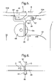
- FIG. 6 is a diagrammatic view along the lines VI-VI in FIG. 5 ;
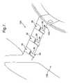
- FIG. 7 is a diagrammatic perspective view of a fifth version of a first embodiment of a securing device
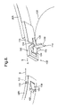
- FIG. 8 is a perspective view of a second embodiment of a securing device
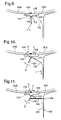
- FIG. 9 is an end view of the securing device shown in FIG. 7 , showing the securing device in a securing position;
- FIG. 10 is a view similar to FIG. 8 showing a first release arrangement releasing the securing device to a non-securing position
- FIG. 11 is a view similar to FIG. 9 showing the first release arrangement inoperative, and a second release arrangement releasing the securing device to a non-securing position.
- FIG. 1 shows a perspective rear view of a gas turbine engine 10 in comprising a pair of thrust reverse structures 12 A, 12 B, hingedly mounted to the pylon 14 .
- the engine 10 is mounted on the aircraft at a pylon 14 .
- the thrust reverser structures 12 A, 12 B each comprise thrust reverser doors (not shown) which act to direct the air flow from the engine fan forwardly, for example to decelerate the aircraft when landing.
- FIG. 1 the thrust reverser structures 12 A, 12 B are shown in an open condition, such as when maintenance is taking place on the engine.
- Each of the thrust reverser structures 12 A, 12 B comprises an outer C-shaped structure 16 A, 16 B, which are secured together in a closed condition by manually operable outer fastening means.
- the outer fastening means are in the form of latches 18 , each comprising respective first and second fastening members 20 , 22 . This arrangement would be immediately appreciated and understood by those skilled in the art and so further description is not necessary.
- Each of the thrust reverser structures 12 A, 12 B also includes an inner C-shaped structure 24 A, 24 B.
- a holding formation in the form of an annular groove 26 extends around the core 28 of the engine 10 .
- a J-shaped elongate curved member 30 A, 30 B extends around each of the inner C-shaped structures 24 A, 24 B and engages in the annular groove 26 , when the thrust reverser structures 12 A, 12 B are in their closed condition.
- Securing devices (not shown in FIG. 1 ) are provided on the inner J-shaped C members 30 A, 30 B to secure the inner C-shaped structures 24 A, 24 B in their closed conditions.
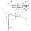
- FIG. 2 shows a close up diagrammatic view of the ends of the J-shaped curved members 30 A, 30 B showing a securing device 34 for securing the J-shaped members together.
- the securing device 34 shown in FIG. 2 , is in the form of a latching arrangement 36 , comprising a movable latch member 38 pivotally attached to the first J-shaped member 30 A by a pivot pin 40 .
- Resilient urging means in the form of a spring 42 is provided around the pin 40 to urge the movable latch member 38 to a latched condition (as shown) in the direction of the arrow A.
- the movable latch member 38 includes a hook formation 44 at its free end, the purpose of which is described below.
- a fixed latch member 46 is fixedly mounted on the second J-shaped member 30 B as shown.
- the fixed latch member 46 includes a hook formation 48 arranged in a position to co-operate with the hook formation 44 on the movable latch member 44 and prevent opening of the J-shaped members 30 A, 30 B.
- the fixed latch member 46 also includes a cam surface 50 which is initially engaged by the hook formation on the movable latch member 38 when the first and second J-shaped members are brought together in the directions indicated by the arrows B and C.
- the hook formation 44 on the movable latch member 38 rides over the cam surface 50 and in so doing pivots outwardly in the direction opposite to the arrow A.
- the spring 42 moves the movable latch member 38 in the direction of the arrow A to the latched condition, shown in FIG. 2 .
- a first release arrangement in the form of a cable 52 which can extend across suitable cable guides (not shown) and housings (not shown).
- the cable 52 is attached to a free end 56 of a release member 54 , which, in turn, is attached to the movable latch member 38 at a region adjacent the hook formation 44 .
- a second release arrangement 58 is provided in case the cable 52 is inoperative, for example if it breaks.
- the second release arrangement 58 comprises a pneumatic or hydraulic ram arrangement comprising a feed line 60 for feeding a pneumatic or hydraulic fluid to a cylinder 62 in which a piston 64 is mounted.
- a rod 66 extends from the piston towards the free end region 56 of the release member 54 .
- the second release arrangement 58 can be used to open the latch arrangement 36 .
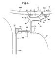
- FIGS. 3 , 6 there is shown a further version of the embodiment shown in FIG. 2 .
- FIGS. 3 to 6 shows a latch arrangement 36 having many of the same features as the latch arrangement 36 shown in FIG. 2 and these have been designated with the same reference numerals.
- the latch arrangement shown in FIG. 3 differs from the latch arrangement shown in FIG. 2 in that the second release arrangement 58 comprises a pull rod 70 insertable through an aperture 72 in the form of a hatch in the casing of the thrust reverser structure 12 A.
- the pull rod 70 comprises an elongate shank 74 having an enlarged end portion 76 .
- FIG. 3A shows a view in the direction of the arrow III in FIG. 3 of the release member 54 , which defines an aperture 78 .
- the aperture 78 has an enlarged region 80 through which the enlarged end 76 of the pull rod 70 can be inserted, and a narrow region 82 .
- the pull rod 70 can be moved downwardly so that the shank is disposed within the narrow region 82 of the aperture 78 .
- the enlarged end 76 engages the release member 54 , which is then pulled in the direction of the arrow D, to move the movable latch member 38 to its unlatched condition.
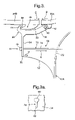
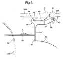
- the second release arrangement comprises a push rod 86 which is insertable in the direction indicated by the arrow F through an aperture 88 in the form of a hatch in the casing of the thrust reverser structure 12 B.
- the second release arrangement comprises a conical or frustoconical cam member 90 attached to a cable 92 .
- the cam member 90 has a cam surface 91 to engage the release member 54 .
- the cable 92 extends substantially at right angles to the cable 52 .
- the cam member 90 is also moved in the same direction.
- the cam surface 91 slides over the release formation 54 moving it in the direction of the arrow D thereby moving the movable latch member to the unlatched condition.
- FIG. 7 three latching arrangements 36 are shown diagrammatically.
- Each of the movable latch members 38 is pivotally mounted by a single hinge pin 100 .
- the hinge pin 100 By removing the hinge pin 100 , for example by sliding it out, the movable latch members are no longer attached to the thrust reverser structure 12 B, which is thus no longer attached by the latching arrangements 36 to the other thrust reverser structure 12 A.
- FIGS. 8 to 11 there is shown a second embodiment comprising a detent arrangement 102 comprising a movable detent member 104 mounted on the second J-shaped member 30 B, and a fixed detent member 106 mounted on the first J-shaped member 30 A.
- the movable detent member 104 has a cam surface 108 and is pivotally mounted in an aperture 105 of the second J-shaped member 30 B by a pivot pin 110 .
- the movable detent member 104 is pivotally movable about the pivot pin 110 between an extended condition as shown in FIG. 8 and a retracted condition, in which the movable detent member 104 lies within the aperture 105 .
- Resilient urging means in the form of a spring 112 (shown in broken lines in FIG. 8 ) urges the movable detent member 104 to the extended condition.
- the fixed detent member 106 extends from the first J-shaped member 30 A to engage the movable detent member 104 .
- the two ends of the first and second J-shaped members 30 A, 30 B and the fixed and movable detent members 104 , 106 are brought together by being moved in the respective directions indicated by the arrows G and H.
- the fixed detent member 106 engages the cam surface 108 of the movable detent member 104
- the movable detent member 104 pivots about the pivot pin 110 to its retracted position lying flush with the second J-shaped member.
- the fixed detent member 106 defines an aperture 107 to receive the movable detent member 104 , when the movable detent member 104 is in its extended condition.
- the fixed detent member 106 slides over the retracted movable detent member 104 , until the first and second J-shaped members are fully closed. In this position, the spring 112 moves the movable detent member 104 to its extended condition in the aperture 107 of the fixed detent member 106 , thus securing the fixed detent member 106 to the movable detent member 104 .
- the fixed detent member 106 carries a relapse member 114 in the form of a pivotally mounted T-shaped member.
- the T-shaped member 114 is pivotally attached to lugs 116 on the fixed detent member 106 by a pivot member 118 at the junction of the arms of the T-shaped member.
- a first release arrangement comprising a cable 120 extends from a first arm 122 of the T-shaped member 114 .
- a second arm 124 opposite the first arm 122 is arranged over the aperture 107 in the fixed detent member 106 (see FIG. 9 ).
- the T-shaped member 114 is pivoted about the pivot member 118 , in the direction of the arrow H, so that the second arm 122 pushes the movable detent member to its retracted condition thereby releasing the first and second J-shaped members 30 A, 30 B so that they can move in the directions indicated by the arrows J and K.
- an elongate threaded screwer 126 can be threadably received in a threaded aperture 128 in the casing of the thrust reversal structure 12 A. As the screw 126 is screwed into the aperture 128 , it engages a third arm 130 of the T-shaped member 114 .
- the third arm 130 is connected to the first and second arms 122 , 124 at their junction with each other.
- the pushing of the screw 126 against the third arm 130 causes the T-shaped member 114 to pivot about the pivot member 118 in the direction of the arrow H in FIG. 11 so that the second arm 124 pushes the movable detent member 104 to its retracted condition so that the fixed detent member 106 can release itself from the movable detent member 104 and the two J-shaped members can move apart as indicated by the arrows K and J.
Landscapes
- Engineering & Computer Science (AREA)
- Mechanical Engineering (AREA)
- Chemical & Material Sciences (AREA)
- Combustion & Propulsion (AREA)
- General Engineering & Computer Science (AREA)
- Lock And Its Accessories (AREA)
- Pivots And Pivotal Connections (AREA)
Abstract
A thrust reverser structure for a gas turbine engine, the structure comprising an outer structure and an inner structure, the structure is capable of being secured in a closed position via outer fastening members on the outer structure, characterised in that the structure is capable of being further secured on the inner structure via a securing device having a securing position and first and second release arrangements, each release arrangement being operable to release the securing device to a non-securing position.
Description
- This invention relates to securing assemblies. More particularly, but not exclusively, the invention relates to securing assemblies for use in securing inner regions of thrust reverser structures of gas turbine engines.
- The thrust reverser structures of a gas turbine engine are hinged at the pylon. When the thrust reverser structures are closed, latches secure the outer J blades to one another, thereby holding the outer J blades in the outer V grooves. The thrust reverser structures also include inner J blades and inner V grooves but the inner J blades are not secured to one another. There is thus a danger that the inner J blades may become dislodged from the inner V grooves.
- According to one aspect of this invention, there is, provided a thrust reverser structure for a gas turbine engine, the structure comprising an outer structure and an inner structure, the structure is capable of being secured in a closed position via outer fastening members on the outer structure, characterised in that the structure is capable of being further secured on the inner structure via a securing device having a securing position and first and second release arrangements, each release arrangement being operable to release the securing device to a non-securing position.
- Preferably, the securing device can secure the thrust reverser structure to one another in a closed condition. Each release arrangement is desirably operable to release the securing device and allow the thrust reverser structure to move to an open condition.
- Preferably, the first release arrangement is a main release arrangement and may be disposed for convenient use by a user. The second release arrangement may be operated when the first release arrangement is inoperable. The second release arrangement may be a subsidiary release arrangement.
- The securing device may comprise a first securing member mountable on a first of the thrust reverser structure. The first securing member may extend from said first thrust reverser structure to a second of the thrust reverser structures when the securing device is in the securing position.
- The securing device may comprise a second securing member mountable on a second of the thrust reverser structure. Conveniently, the first and second securing members can co-operate with each other to secure the first securing member to the second securing member.
- In a first embodiment, the securing device may comprise a latching arrangement. Desirably, the first securing member comprises a movable latch member mounted on said first thrust reverser structure. Conveniently, the movable latch member is pivotally mounted on said first thrust reverser structure.
- In the first embodiment, the second securing member comprises a fixed latch member, mounted on the second thrust reverser structure. Conveniently, the fixed latch member is fixedly mounted on said second thrust reverser structure.
- Desirably, the movable latch member is movable between latched and unlatched conditions. Preferably, the movable and fixed latch members comprise co-operating formations, which can co-operate with each other when the movable latch member is in the latched condition to secure the movable latch member to the fixed latch member and thereby secure the first and second thrust reverser structure to each other.
- Preferably, resilient urging means is provided to urge the movable latch member to the latched condition. The resilient urging means may comprise a spring.
- Preferably, the co-operating formations comprise hook formations. The hook formation can desirably hook onto one another when the securing device is in the securing position.
- Preferably, the movable latch member extends from the first thrust reverser structure to the second thrust reverser structure to co-operate with the fixed latch member when the securing device is in the securing position.
- The first release arrangement may comprise a flexible member, such as a cable. The flexible member may be attached to the movable latch member to move the movable latch member from the latched to the unlatched condition, when a force is applied to the flexible member, for example by pulling the flexible member conveniently the flexible member can extend to a region external of the first and second thrust reverser structure for ease of use.
- Preferably resilient urging means is provided on the movable latch member to urge the movable latch member to the latched condition.
- A release formation may be provided on the movable latch member. The release formation may interact with the first and second release arrangements. The release formation may extend from the movable latch member and may comprise a lever. The first release arrangement may be secured to the release formation. The second release arrangement may include an opening member to engage the release formation.
- In the second embodiment, the securing device may comprise a detent arrangement. Desirably, the first securing member comprises a fixed detent member mounted on said first thrust reverser structure. Conveniently, the fixed detent member is fixedly mounted relative to said first thrust reverser structure.
- In the second embodiment, the second securing member comprises a movable detent member movably mounted relative to said second thrust reverser structure. Conveniently, the movably detent member is movable in a direction transverse to the second thrust reverser structure. Preferably, the movable detent member is pivotally mounted on the second thrust reverser structure. The movable detent member may be movable between an extended condition and a retracted condition. Preferably, when the second detent member is in the extended condition, the first and second detent members can co-operate with each other to secure the fixed and movable detent members to each other. Preferably, when the movable detent member is in the retracted condition, the fixed and movable detent members can be released from each other.
- Resilient urging means, for example a spring, may be provided to urge the movable detent member to the extended condition.
- The fixed detent member may comprise an engagement surface to engage the movable detent member when the fixed and movable detent members are in the securing position. The engagement surface may be provided by an aperture or recess in the fixed detent member.
- The second release arrangement may comprise a flexible member, such as a cable. The flexible member may be attached to the movable detent member to move the movable detent member from the extended to the retracted condition when a force is applied to the flexible member, for example by pulling the flexible member.
- Conveniently, the flexible member can extend to a region external of the first and second thrust reverser structures for ease of use.
- A release member may be provided on the fixed detent member for engagement with an opening member. The release member on the fixed detent member may comprise a pivoting member pivotally mounted on the fixed detent member.
- The pivoting member may be a T-shaped member. Preferably a first arm portion of the T-shaped member may be attached to the flexible member. A second arm portion of the T-shaped member may engage the movable detent member, whereby applying an appropriate force to the first arm causes the T-shaped member to pivot to move the second arm into engagement with the movable detent member to move the movable detent member to the retracted position.
- The T-shaped member may include a leg portion extending transverse to the first and second arm portions. The second release arrangement may comprise an opening member to engage the release formation to cause the release formation to move the movable detent member to the retracted condition.
- The opening member may comprise a force applying arrangement to apply a force to the release formation. The opening member may comprise a substantially rigid member to pull or push said release formation. The opening member may be elongate.
- In one embodiment, the opening member may comprise a bolt which may be receivable in a release aperture in one of the first and second thrust reverser structures. Desirably, when the opening member is received in the release aperture, the opening member engages the release formation to release the securing device to the non-secured position.
- The release aperture and the opening member may be threaded, whereby the opening member can threadably engage the threads in the opening and on screwing the opening member into the aperture, the opening member can engage the release formation to release the securing device to the non-secured position.
- Alternatively, the opening member may comprise a pneumatic or hydraulic ram which, when operated, can engage the release formation to release the securing device to the non-secured position.
- In another alternative, the release formation may define an aperture for receiving on end portion of the opening member. The opening member may comprise an elongate shank and an enlarged end portion. The aperture in the release member may have a first region to receive the enlarged end portion and a second narrow region into which the shank can be slid, wherein the opening member can pull the release formation to move the movable latch member to the unlatched condition.
- In another embodiment the opening member may comprise a rod insertable through a hatch in the first or second thrust reverser structure to push the release formation and move the movable latch member to the unlatched condition.
- In another embodiment, the opening member may comprise a cam member, which may be attached to a further flexible member. The cam member may be of a conical or frustoconical configuration. The cam member may be arranged to move transverse to the direction of motion of the movable latch member. When the cam member is moved, the cam member may slide across the release formation to move the release formation in the direction transverse to the direction of movement of the cam member.
- Another alternative of the opening member comprises a hinge pin extending through the pivot, of the movable latch member wherein removal of the hinge pin releases the movable latch member from its latched condition.
- Embodiments of the invention will now be described by way of example only, with reference to the accompanying drawings, in which:
-
FIG. 1 is a rear perspective end view of a gas turbine engine; -
FIG. 2 is a diagrammatic end view of a first version of a first embodiment of a securing device; -
FIG. 3 is a diagrammatic end view of a second version of a first embodiment of a securing device; -
FIG. 3A is a view in the direction of the arrow III inFIG. 3 ; -
FIG. 4 is a diagrammatic end view of a third version of a first embodiment of a securing device; -
FIG. 5 is a diagrammatic end view of a fourth version of a first embodiment of a securing device; -
FIG. 6 is a diagrammatic view along the lines VI-VI inFIG. 5 ; -
FIG. 7 is a diagrammatic perspective view of a fifth version of a first embodiment of a securing device; -
FIG. 8 is a perspective view of a second embodiment of a securing device; -
FIG. 9 is an end view of the securing device shown inFIG. 7 , showing the securing device in a securing position; -
FIG. 10 is a view similar toFIG. 8 showing a first release arrangement releasing the securing device to a non-securing position; and -
FIG. 11 is a view similar toFIG. 9 showing the first release arrangement inoperative, and a second release arrangement releasing the securing device to a non-securing position. -
FIG. 1 shows a perspective rear view of agas turbine engine 10 in comprising a pair ofthrust reverse structures pylon 14. Theengine 10 is mounted on the aircraft at apylon 14. - The
thrust reverser structures - In
FIG. 1 thethrust reverser structures - Each of the
thrust reverser structures structure latches 18, each comprising respective first andsecond fastening members - Each of the
thrust reverser structures structure annular groove 26 extends around thecore 28 of theengine 10. A J-shaped elongatecurved member structures annular groove 26, when thethrust reverser structures - Securing devices (not shown in
FIG. 1 ) are provided on the inner J-shapedC members structures -
FIG. 2 shows a close up diagrammatic view of the ends of the J-shapedcurved members device 34 for securing the J-shaped members together. - The securing
device 34, shown inFIG. 2 , is in the form of a latchingarrangement 36, comprising amovable latch member 38 pivotally attached to the first J-shapedmember 30A by apivot pin 40. Resilient urging means in the form of aspring 42 is provided around thepin 40 to urge themovable latch member 38 to a latched condition (as shown) in the direction of the arrow A. Themovable latch member 38 includes ahook formation 44 at its free end, the purpose of which is described below. - A fixed
latch member 46 is fixedly mounted on the second J-shapedmember 30B as shown. The fixedlatch member 46 includes ahook formation 48 arranged in a position to co-operate with thehook formation 44 on themovable latch member 44 and prevent opening of the J-shapedmembers - The fixed
latch member 46 also includes acam surface 50 which is initially engaged by the hook formation on themovable latch member 38 when the first and second J-shaped members are brought together in the directions indicated by the arrows B and C. Thehook formation 44 on themovable latch member 38 rides over thecam surface 50 and in so doing pivots outwardly in the direction opposite to the arrow A. When the first and second J-shaped members are fully closed and thehook formation 44 on the movable latch member has passed over thehook formation 48 thespring 42 moves themovable latch member 38 in the direction of the arrow A to the latched condition, shown inFIG. 2 . - In order to release the
movable latch member 38 from the fixedlatch member 46 and allow the J-shaped members to open a first release arrangement in the form of acable 52, which can extend across suitable cable guides (not shown) and housings (not shown). Thecable 52 is attached to afree end 56 of arelease member 54, which, in turn, is attached to themovable latch member 38 at a region adjacent thehook formation 44. By applying a force to thefree end region 56 of therelease member 54 in the direction indicated by the arrow D thehook formation 44 of themovable latch member 38 is disengaged from thehook formation 48 of the fixedlatch member 46. This force can be applied by pulling the cable D. - A
second release arrangement 58 is provided in case thecable 52 is inoperative, for example if it breaks. Thesecond release arrangement 58 comprises a pneumatic or hydraulic ram arrangement comprising afeed line 60 for feeding a pneumatic or hydraulic fluid to acylinder 62 in which apiston 64 is mounted. Arod 66 extends from the piston towards thefree end region 56 of therelease member 54. Thus, by supplying pneumatic or hydraulic fluid to thecylinder 62, thepiston 64 and therod 66 are moved in the direction of the arrow E to push thefree end region 56 in the direction of the arrow D. This disengages thehook formation 44 of themovable latch member 38 from thehook formation 48 of the fixedlatch member 46 to move themovable latch member 38 to an unlatched condition and allow the J-shapedmembers - Thus, in the event that the
cable 52 snaps or is otherwise inoperable, thesecond release arrangement 58 can be used to open thelatch arrangement 36. - Referring to
FIGS. 3 , 6 there is shown a further version of the embodiment shown inFIG. 2 .FIGS. 3 to 6 shows alatch arrangement 36 having many of the same features as thelatch arrangement 36 shown inFIG. 2 and these have been designated with the same reference numerals. - The latch arrangement shown in
FIG. 3 differs from the latch arrangement shown inFIG. 2 in that thesecond release arrangement 58 comprises apull rod 70 insertable through anaperture 72 in the form of a hatch in the casing of thethrust reverser structure 12A. Thepull rod 70 comprises anelongate shank 74 having anenlarged end portion 76. -
FIG. 3A shows a view in the direction of the arrow III inFIG. 3 of therelease member 54, which defines anaperture 78. Theaperture 78 has anenlarged region 80 through which theenlarged end 76 of thepull rod 70 can be inserted, and anarrow region 82. - When the
enlarged end 76 has been inserted through theenlarged region 80 of theaperture 78, thepull rod 70 can be moved downwardly so that the shank is disposed within thenarrow region 82 of theaperture 78. In this position, by pulling on thepull rod 70 in the direction of the arrow E, theenlarged end 76 engages therelease member 54, which is then pulled in the direction of the arrow D, to move themovable latch member 38 to its unlatched condition. - In
FIG. 4 , the second release arrangement comprises apush rod 86 which is insertable in the direction indicated by the arrow F through anaperture 88 in the form of a hatch in the casing of thethrust reverser structure 12B. When thepush rod 86 engages thefree end region 56 of therelease member 54, continued pushing in the direction of the arrow F moves themovable latch member 38 to its unlatched condition. - In
FIGS. 5 and 6 , the second release arrangement comprises a conical orfrustoconical cam member 90 attached to acable 92. - The
cam member 90 has acam surface 91 to engage therelease member 54. Thecable 92 extends substantially at right angles to thecable 52. By pulling thecable 92 in the direction indicated by the arrow G, thecam member 90 is also moved in the same direction. Thecam surface 91 slides over therelease formation 54 moving it in the direction of the arrow D thereby moving the movable latch member to the unlatched condition. - In
FIG. 7 , three latchingarrangements 36 are shown diagrammatically. Each of themovable latch members 38 is pivotally mounted by asingle hinge pin 100. By removing thehinge pin 100, for example by sliding it out, the movable latch members are no longer attached to thethrust reverser structure 12B, which is thus no longer attached by the latchingarrangements 36 to the other thrust reverserstructure 12A. - Referring to
FIGS. 8 to 11 there is shown a second embodiment comprising adetent arrangement 102 comprising amovable detent member 104 mounted on the second J-shapedmember 30B, and a fixeddetent member 106 mounted on the first J-shapedmember 30A. - The
movable detent member 104 has acam surface 108 and is pivotally mounted in anaperture 105 of the second J-shapedmember 30B by apivot pin 110. Themovable detent member 104 is pivotally movable about thepivot pin 110 between an extended condition as shown inFIG. 8 and a retracted condition, in which themovable detent member 104 lies within theaperture 105. - Resilient urging means in the form of a spring 112 (shown in broken lines in
FIG. 8 ) urges themovable detent member 104 to the extended condition. - The fixed
detent member 106 extends from the first J-shapedmember 30A to engage themovable detent member 104. The two ends of the first and second J-shapedmembers movable detent members detent member 106 engages thecam surface 108 of themovable detent member 104, themovable detent member 104 pivots about thepivot pin 110 to its retracted position lying flush with the second J-shaped member. - The fixed
detent member 106 defines an aperture 107 to receive themovable detent member 104, when themovable detent member 104 is in its extended condition. - The fixed
detent member 106 slides over the retractedmovable detent member 104, until the first and second J-shaped members are fully closed. In this position, thespring 112 moves themovable detent member 104 to its extended condition in the aperture 107 of the fixeddetent member 106, thus securing the fixeddetent member 106 to themovable detent member 104. - The fixed
detent member 106 carries arelapse member 114 in the form of a pivotally mounted T-shaped member. The T-shapedmember 114 is pivotally attached to lugs 116 on the fixeddetent member 106 by apivot member 118 at the junction of the arms of the T-shaped member. - A first release arrangement comprising a
cable 120 extends from afirst arm 122 of the T-shapedmember 114. Asecond arm 124, opposite thefirst arm 122 is arranged over the aperture 107 in the fixed detent member 106 (seeFIG. 9 ). When a force is applied to thecable 120 in the direction of the arrow I (seeFIG. 10 ), the T-shapedmember 114 is pivoted about thepivot member 118, in the direction of the arrow H, so that thesecond arm 122 pushes the movable detent member to its retracted condition thereby releasing the first and second J-shapedmembers - In the event that the
cable 120 breaks, an elongate threadedscrewer 126 can be threadably received in a threadedaperture 128 in the casing of thethrust reversal structure 12A. As thescrew 126 is screwed into theaperture 128, it engages athird arm 130 of the T-shapedmember 114. Thethird arm 130 is connected to the first andsecond arms - The pushing of the
screw 126 against thethird arm 130 causes the T-shapedmember 114 to pivot about thepivot member 118 in the direction of the arrow H inFIG. 11 so that thesecond arm 124 pushes themovable detent member 104 to its retracted condition so that the fixeddetent member 106 can release itself from themovable detent member 104 and the two J-shaped members can move apart as indicated by the arrows K and J. - Although this description of the preferred embodiments has described only a single securing device on each of the inner C-shaped
structures members - Various modifications can be made without departing from the scope of the invention.
Claims (43)
1. A thrust reverser structure for a gas turbine engine, the structure comprising an outer structure and an inner structure, the structure is capable of being secured in a closed position via outer fastening members on the outer structure, characterised in that the structure is capable of being further secured on the inner structure via a securing device having a securing position and first and second release arrangements, each release arrangement being operable to release the securing device to a non-securing position.
2. A thrust reverser structure according to claim 1 characterised in that the securing device can secure the thrust reverser structures to one another in a closed condition, and each release arrangement is desirably operable to release the securing device and allow the thrust reverser structures to move to an open condition.
3. A thrust reverser structure according to claim 1 characterised in that the first release arrangement is a main release arrangement and the second release arrangement can be operated when the first release arrangement is inoperable.
4. A thrust reverser structure according to claim 1 characterised in that the securing device comprises a first securing member mountable on a first of the thrust reverser structures, the first securing member extending from said first thrust reverser structure to a second of the thrust reverser structures when the securing device is in the securing position.
5. A thrust reverser structure according to claim 4 characterised in that the securing device comprises a second securing member mountable on a second of the thrust reverser structures, wherein the first and second securing members can co-operate with each other to secure the first securing member to the second securing member.
6. A thrust reverser structure according to claim 4 characterised in that the securing device comprises a latching arrangement, and the first securing member comprises a movable latch member mounted on said first thrust reverser structure, wherein the movable latch member is movable between latched and unlatched conditions.
7. A thrust reverser structure according to claim 6 characterised in that the movable latch member is pivotally mounted on said first thrust reverser structure.
8. A thrust reverser structure according to claim 6 characterised in that the second securing member comprises a fixed latch member mounted on the second thrust reverser structure.
9. A thrust reverser structure according to claim 8 characterised in that the movable and fixed latch members comprise co-operating formations, which can co-operate with each other when the movable latch member is in the latched condition to secure the movable latch member to the fixed latch member and thereby secure the first and second thrust reverser structures to each other.
10. A thrust reverser structure according to claim 9 characterised in that the co-operating formations comprise hook formations, wherein the hook formations can hook onto one another when the securing device is in the securing position.
11. A thrust reverser structure according to claim 8 characterised in that the movable latch member extends from the first thrust reverser structure to the second thrust reverser structure to co-operate with the fixed latch member when the securing device is in the securing position.
12. A thrust reverser structure according to claim 6 characterised in that the first release arrangement comprises a flexible member attached to the movable latch member to move the movable latch member from the latched to the unlatched condition, when a force is applied to the flexible member.
13. A thrust reverser structure according to claim 12 characterised in that the flexible member extends to a region external of the first and second thrust reverser structures for ease of use.
14. A thrust reverser structure according to claim 6 characterised in that a release formation is provided on the movable latch member, the release formation interacting with the first and second release arrangements.
15. A thrust reverser structure according to claim 14 characterised in that the release formation extends from the movable latch member and comprises a lever.
16. A thrust reverser structure according to claim 14 characterised in that the first release arrangement is secured to the release formation.
17. A thrust reverser structure according to claim 14 characterised in that the second release arrangement includes an opening member to engage the release formation.
18. A thrust reverser structure according to claims 6 characterised in that resilient urging means is provided on the movable latch member to urge the movable latch member to the latched condition.
19. A thrust reverser structure according to claim 1 characterised in that the securing device comprises a detent arrangement, wherein the first securing member comprises a fixed detent member mounted on said first thrust reverser structure.
20. A thrust reverser structure according to claim 19 characterised in that the second securing member comprises a movable detent member movably mounted relative to said second thrust reverser structure.
21. A thrust reverser structure according to claim 20 characterised in that the movable detent member is movable in a direction transverse to the second thrust reverser structure.
22. A thrust reverser structure according to claim 20 characterised in that the movable detent member is pivotally mounted on the second thrust reverser structure.
23. A thrust reverser structure according to claim 20 characterised in that the movable detent member is movable between an extended condition and a retracted condition, wherein when the movable detent member is in the extended condition, the fixed and movable detent members can co-operate with each other to secure the fixed and movable detent members to each other, and when the movable detent member is in the retracted condition, the fixed and movable detent members can be released from each other.
24. A thrust reverser structure according to claim 23 characterised in that resilient urging means is provided to urge the movable detent member to the extended condition.
25. A thrust reverser structure according to claims 22 characterised in that the fixed detent member comprises an engagement surface to engage the movable detent member when the fixed and movable detent members are in the securing position.
26. A thrust reverser structure according to claim 27 characterised in that the engagement surface is provided by an aperture or recess in the fixed detent member.
27. A thrust reverser structure according to claims 20 characterised in that the second release arrangement comprises a flexible member arranged to move the movable detent member from the extended to the retracted condition when a force is applied to the flexible member.
28. A thrust reverser structure according to claim 27 characterised in that the flexible member can extend to a region external of the first and second thrust reverser structures for ease of use.
29. A thrust reverser structure according to claim 27 characterised in that a release member is provided on the fixed detent member for engagement with an opening member, said release member comprising a pivoting member pivotally mounted on the fixed detent member.
30. A thrust reverser structure according to claim 29 characterised in that the flexible member can extend to a region external of the first and second thrust reverser structures for ease of use, and the pivoting member comprises a T-shaped member, wherein a first arm portion of the T-shaped member is attached to the flexible member, and a second arm portion of the T-shaped member engages the movable detent member, whereby applying an appropriate force to the first arm portion causes the T-shaped member to pivot to move the second arm portion into engagement with the movable detent member to move the movable detent member to the retracted position.
31. A thrust reverser structure according to claim 30 characterised in that the T-shaped member includes a release formation comprising a leg portion extending transverse to the first and second arm portions wherein the second release arrangement comprises an opening member to engage the release formation to cause the release formation to move the movable detent member to the retracted condition.
32. A thrust reverser structure according to claim 31 characterised in that the opening member comprises a force applying arrangement to apply a force to the release formation.
33. A thrust reverser structure according to claim 32 characterised in that the opening member comprises a substantially rigid member to pull or push said release formation.
34. A thrust reverser structure according to claim 33 characterised in that the opening member is elongate.
35. A thrust reverser structure according to claim 14 characterised in that the opening member comprises a bolt receivable in a release aperture in one of the first and second thrust reverser structures, wherein when the opening member is received in the release aperture, the opening member engages the release formation to release the securing device to the non-secured position.
36. A thrust reverser structure according to claim 35 characterised in that the release aperture and the opening member are threaded, whereby the opening member can threadably engage the threads in the release aperture and on screwing the opening member into the aperture, the opening member can engage the release formation to release the securing device to the non-secured position.
37. A thrust reverser structure according to claims 14 characterised in that the opening member comprises a pneumatic or hydraulic ram which, when operated, can engage the release formation to release the securing device to the non-secured position.
38. A thrust reverser structure according to claim 14 characterised in that the release formation defines an aperture for receiving one end portion of the opening member, the opening member comprising an elongate shank and an enlarged end portion.
39. A thrust reverser structure according to claim 38 characterised in that the aperture in the release member has a first region to receive the enlarged end portion and a second narrow region in which the shank can be slid, wherein the opening member can pull the release formation to move the movable latch member to the unlatched condition.
40. A thrust reverser structure according to claim 14 characterised in that the opening member comprises a rod insertable through a hatch in the first or second thrust reverser structure to push the release formation and move the movable latch member to the unlatched condition.
41. A thrust reverser structure according to claim 14 characterised in that the opening member comprises a cam member attached to a further flexible member, the cam member being arranged to move transverse to the direction of motion of the movable latch member, whereby when the cam member is moved, the cam member slides across the release formation to move the release formation in the direction transverse to the direction of movement of the cam member.
42. A thrust reverser structure according to claim 41 characterised in that the cam member is of a conical or frustoconical configuration.
43. A thrust reverser structure according to claim 14 characterised in that the opening member comprises a hinge pin extending through the pivot, of the movable latch member wherein removal of the hinge pin releases the movable latch member from its latched condition.
Applications Claiming Priority (2)
| Application Number | Priority Date | Filing Date | Title |
|---|---|---|---|
| GBGB0426916.3A GB0426916D0 (en) | 2004-12-08 | 2004-12-08 | Securing assembly |
| GB0426916.3 | 2004-12-08 |
Publications (1)
| Publication Number | Publication Date |
|---|---|
| US20080098720A1 true US20080098720A1 (en) | 2008-05-01 |
Family
ID=34073388
Family Applications (1)
| Application Number | Title | Priority Date | Filing Date |
|---|---|---|---|
| US11/272,717 Abandoned US20080098720A1 (en) | 2004-12-08 | 2005-11-15 | Securing assembly |
Country Status (3)
| Country | Link |
|---|---|
| US (1) | US20080098720A1 (en) |
| EP (1) | EP1669553A2 (en) |
| GB (1) | GB0426916D0 (en) |
Cited By (12)
| Publication number | Priority date | Publication date | Assignee | Title |
|---|---|---|---|---|
| US20060277895A1 (en) * | 2005-05-11 | 2006-12-14 | Thornock Russel L | Aircraft systems including cascade thrust reversers |
| US20070007388A1 (en) * | 2005-06-27 | 2007-01-11 | Harrison Geoffrey E | Thrust reversers including locking assemblies for inhibiting deflection |
| US7600371B2 (en) | 2005-10-18 | 2009-10-13 | The Boeing Company | Thrust reversers including support members for inhibiting deflection |
| US20110101158A1 (en) * | 2005-03-29 | 2011-05-05 | The Boeing Company | Thrust Reversers Including Monolithic Components |
| US20140131515A1 (en) * | 2011-01-17 | 2014-05-15 | Aircelle | Aircraft turbojet engine thrust reverser with a reduced number of latches |
| CN105339640A (en) * | 2013-07-02 | 2016-02-17 | Mra系统有限公司 | Engine and band clamp |
| US9435293B2 (en) | 2013-02-22 | 2016-09-06 | United Technologies Corporation | Full ring sliding nacelle with thrust reverser |
| US9573695B2 (en) | 2013-02-22 | 2017-02-21 | United Technologies Corporation | Integrated nozzle and plug |
| US9581108B2 (en) | 2013-02-22 | 2017-02-28 | United Technologies Corporation | Pivot thrust reverser with multi-point actuation |
| US10060292B2 (en) | 2013-03-14 | 2018-08-28 | United Technologies Corporation | Castellated latch mechanism for a gas turbine engine |
| US10339571B2 (en) | 2011-06-30 | 2019-07-02 | Intel Corporation | Method and apparatus for dynamic, real-time ad insertion based on meta-data within a hardware based root of trust |
| EP4123152A1 (en) * | 2021-07-20 | 2023-01-25 | Rohr, Inc. | Thrust reverser system latch assembly and method of operating same |
Families Citing this family (1)
| Publication number | Priority date | Publication date | Assignee | Title |
|---|---|---|---|---|
| FR2970513B1 (en) * | 2011-01-14 | 2015-07-31 | Aircelle Sa | DEVICE FOR CONNECTING A FRAME FRONT TO A BLOWER HOUSING |
Citations (1)
| Publication number | Priority date | Publication date | Assignee | Title |
|---|---|---|---|---|
| US5819527A (en) * | 1995-09-13 | 1998-10-13 | Societe De Construction Des Avions Hurel-Dubois | Electro/hydraulic system for a 2 door thrust reverser |
-
2004
- 2004-12-08 GB GBGB0426916.3A patent/GB0426916D0/en not_active Ceased
-
2005
- 2005-11-10 EP EP05256958A patent/EP1669553A2/en not_active Withdrawn
- 2005-11-15 US US11/272,717 patent/US20080098720A1/en not_active Abandoned
Patent Citations (1)
| Publication number | Priority date | Publication date | Assignee | Title |
|---|---|---|---|---|
| US5819527A (en) * | 1995-09-13 | 1998-10-13 | Societe De Construction Des Avions Hurel-Dubois | Electro/hydraulic system for a 2 door thrust reverser |
Cited By (27)
| Publication number | Priority date | Publication date | Assignee | Title |
|---|---|---|---|---|
| US20110101158A1 (en) * | 2005-03-29 | 2011-05-05 | The Boeing Company | Thrust Reversers Including Monolithic Components |
| US20060277895A1 (en) * | 2005-05-11 | 2006-12-14 | Thornock Russel L | Aircraft systems including cascade thrust reversers |
| US7690190B2 (en) | 2005-05-11 | 2010-04-06 | The Boeing Company | Aircraft systems including cascade thrust reversers |
| US20070007388A1 (en) * | 2005-06-27 | 2007-01-11 | Harrison Geoffrey E | Thrust reversers including locking assemblies for inhibiting deflection |
| US7559507B2 (en) * | 2005-06-27 | 2009-07-14 | The Boeing Company | Thrust reversers including locking assemblies for inhibiting deflection |
| US7600371B2 (en) | 2005-10-18 | 2009-10-13 | The Boeing Company | Thrust reversers including support members for inhibiting deflection |
| US20140131515A1 (en) * | 2011-01-17 | 2014-05-15 | Aircelle | Aircraft turbojet engine thrust reverser with a reduced number of latches |
| US9476383B2 (en) * | 2011-01-17 | 2016-10-25 | Aircelle | Aircraft turbojet engine thrust reverser with a reduced number of latches |
| US11580570B2 (en) | 2011-06-30 | 2023-02-14 | Intel Corporation | Method and apparatus for dynamic, real-time ad insertion based on meta-data within a hardware based root of trust |
| US10339571B2 (en) | 2011-06-30 | 2019-07-02 | Intel Corporation | Method and apparatus for dynamic, real-time ad insertion based on meta-data within a hardware based root of trust |
| US9611048B2 (en) | 2013-02-22 | 2017-04-04 | United Technologies Corporation | ATR axial V-groove |
| US9970388B2 (en) | 2013-02-22 | 2018-05-15 | United Technologies Corporation | Tandem thrust reverser with sliding rails |
| US9573695B2 (en) | 2013-02-22 | 2017-02-21 | United Technologies Corporation | Integrated nozzle and plug |
| US9617009B2 (en) | 2013-02-22 | 2017-04-11 | United Technologies Corporation | ATR full ring sliding nacelle |
| US9631578B2 (en) | 2013-02-22 | 2017-04-25 | United Technologies Corporation | Pivot thrust reverser surrounding inner surface of bypass duct |
| US9670876B2 (en) | 2013-02-22 | 2017-06-06 | United Technologies Corporation | Tandem thrust reverser with sliding rails |
| US9695778B2 (en) | 2013-02-22 | 2017-07-04 | United Technologies Corporation | Tandem thrust reverser with multi-point actuation |
| US9694912B2 (en) | 2013-02-22 | 2017-07-04 | United Technologies Corporation | ATR guide pins for sliding nacelle |
| US9822734B2 (en) | 2013-02-22 | 2017-11-21 | United Technologies Corporation | Tandem thrust reverser with multi-bar linkage |
| US9581108B2 (en) | 2013-02-22 | 2017-02-28 | United Technologies Corporation | Pivot thrust reverser with multi-point actuation |
| US9435293B2 (en) | 2013-02-22 | 2016-09-06 | United Technologies Corporation | Full ring sliding nacelle with thrust reverser |
| US10180117B2 (en) | 2013-02-22 | 2019-01-15 | United Technologies Corporation | Full ring sliding nacelle with thrust reverser |
| US10060292B2 (en) | 2013-03-14 | 2018-08-28 | United Technologies Corporation | Castellated latch mechanism for a gas turbine engine |
| US10190537B2 (en) | 2013-07-02 | 2019-01-29 | Mra Systems, Inc. | Engine and band clamp |
| CN105339640A (en) * | 2013-07-02 | 2016-02-17 | Mra系统有限公司 | Engine and band clamp |
| EP4123152A1 (en) * | 2021-07-20 | 2023-01-25 | Rohr, Inc. | Thrust reverser system latch assembly and method of operating same |
| US11933247B2 (en) | 2021-07-20 | 2024-03-19 | Rohr, Inc. | Thrust reverser system latch assembly and method of operating same |
Also Published As
| Publication number | Publication date |
|---|---|
| EP1669553A2 (en) | 2006-06-14 |
| GB0426916D0 (en) | 2005-01-12 |
Similar Documents
| Publication | Publication Date | Title |
|---|---|---|
| US20080098720A1 (en) | Securing assembly | |
| US6334730B1 (en) | Telescopic rod for opening a mobile cowl, in particular of an aircraft engine bay | |
| RU2436712C2 (en) | Turbojet engine nacelle with lateral opening of flaps | |
| US5826823A (en) | Actuator and safety lock system for pivoting door thrust reverser for aircraft jet engine | |
| US5046689A (en) | Cowling interlock system | |
| EP1286037B1 (en) | Lock for a turbofan engine thrust reverser | |
| US20180245610A1 (en) | Curtain Retention Bracket | |
| US11236700B2 (en) | Three actuator cascade type thrust reverser actuation system | |
| US4549708A (en) | Cowling latch system | |
| US9353559B2 (en) | Latching system for securing two components | |
| US9988157B2 (en) | Fan cowl balking latch | |
| US6604355B1 (en) | Thrust reverser hook latch system | |
| EP3281873B1 (en) | Brake release for aircraft seat | |
| CN102939244A (en) | Turbojet engine nacelle including device for absorbing circumferential stresses | |
| US20120234983A1 (en) | Control surface assembly | |
| US20180362173A1 (en) | Self-latching nacelle | |
| CN103477007A (en) | Locking device with mechanical detection of closing and opening | |
| EP1288479B2 (en) | Thrust reverser sleeve lock | |
| EP1988239B1 (en) | Dual action structural latch | |
| CN101253095B (en) | Dynamic self-locking latch device | |
| CN100424334C (en) | Thrust reverser lock with locking device | |
| US20150307198A1 (en) | Assembly for an aircraft comprising a moveable access panel | |
| US8590287B2 (en) | Device for opening and closing a thrust reverser door of a jet engine | |
| US20080134664A1 (en) | Thrust reverser pin lock | |
| US20250020014A1 (en) | Assembly with an open-door locking system |
Legal Events
| Date | Code | Title | Description |
|---|---|---|---|
| AS | Assignment |
Owner name: ROLLS-ROYCE PLC, GREAT BRITAIN Free format text: ASSIGNMENT OF ASSIGNORS INTEREST;ASSIGNOR:WATSON, MATTHEW PHILLIP;REEL/FRAME:017235/0327 Effective date: 20051108 |
|
| STCB | Information on status: application discontinuation |
Free format text: ABANDONED -- FAILURE TO RESPOND TO AN OFFICE ACTION |