US20080098710A1 - Inlet airflow management system for a pulse detonation engine for supersonic applications - Google Patents
Inlet airflow management system for a pulse detonation engine for supersonic applications Download PDFInfo
- Publication number
- US20080098710A1 US20080098710A1 US11/554,824 US55482406A US2008098710A1 US 20080098710 A1 US20080098710 A1 US 20080098710A1 US 55482406 A US55482406 A US 55482406A US 2008098710 A1 US2008098710 A1 US 2008098710A1
- Authority
- US
- United States
- Prior art keywords
- valve timing
- pulse detonation
- stator
- detonation
- devices
- Prior art date
- Legal status (The legal status is an assumption and is not a legal conclusion. Google has not performed a legal analysis and makes no representation as to the accuracy of the status listed.)
- Granted
Links
- 238000005474 detonation Methods 0.000 title claims abstract description 117
- 230000000903 blocking effect Effects 0.000 claims abstract description 19
- 238000004891 communication Methods 0.000 claims description 9
- 238000011144 upstream manufacturing Methods 0.000 description 13
- 238000000034 method Methods 0.000 description 12
- 239000000446 fuel Substances 0.000 description 7
- 230000001902 propagating effect Effects 0.000 description 7
- 238000002347 injection Methods 0.000 description 3
- 239000007924 injection Substances 0.000 description 3
- 238000002485 combustion reaction Methods 0.000 description 2
- 238000004200 deflagration Methods 0.000 description 2
- 239000000203 mixture Substances 0.000 description 2
- 238000010926 purge Methods 0.000 description 2
- 239000007795 chemical reaction product Substances 0.000 description 1
- 238000005516 engineering process Methods 0.000 description 1
- 230000000977 initiatory effect Effects 0.000 description 1
- 230000013011 mating Effects 0.000 description 1
- 230000004048 modification Effects 0.000 description 1
- 238000012986 modification Methods 0.000 description 1
- 239000007800 oxidant agent Substances 0.000 description 1
- 239000000047 product Substances 0.000 description 1
- 230000001105 regulatory effect Effects 0.000 description 1
- VEMKTZHHVJILDY-UHFFFAOYSA-N resmethrin Chemical compound CC1(C)C(C=C(C)C)C1C(=O)OCC1=COC(CC=2C=CC=CC=2)=C1 VEMKTZHHVJILDY-UHFFFAOYSA-N 0.000 description 1
- 230000029058 respiratory gaseous exchange Effects 0.000 description 1
- 230000035939 shock Effects 0.000 description 1
- 238000004513 sizing Methods 0.000 description 1
Images


Classifications
-
- F—MECHANICAL ENGINEERING; LIGHTING; HEATING; WEAPONS; BLASTING
- F02—COMBUSTION ENGINES; HOT-GAS OR COMBUSTION-PRODUCT ENGINE PLANTS
- F02C—GAS-TURBINE PLANTS; AIR INTAKES FOR JET-PROPULSION PLANTS; CONTROLLING FUEL SUPPLY IN AIR-BREATHING JET-PROPULSION PLANTS
- F02C5/00—Gas-turbine plants characterised by the working fluid being generated by intermittent combustion
- F02C5/02—Gas-turbine plants characterised by the working fluid being generated by intermittent combustion characterised by the arrangement of the combustion chamber in the chamber in the plant
-
- F—MECHANICAL ENGINEERING; LIGHTING; HEATING; WEAPONS; BLASTING
- F02—COMBUSTION ENGINES; HOT-GAS OR COMBUSTION-PRODUCT ENGINE PLANTS
- F02K—JET-PROPULSION PLANTS
- F02K7/00—Plants in which the working fluid is used in a jet only, i.e. the plants not having a turbine or other engine driving a compressor or a ducted fan; Control thereof
- F02K7/02—Plants in which the working fluid is used in a jet only, i.e. the plants not having a turbine or other engine driving a compressor or a ducted fan; Control thereof the jet being intermittent, i.e. pulse-jet
- F02K7/06—Plants in which the working fluid is used in a jet only, i.e. the plants not having a turbine or other engine driving a compressor or a ducted fan; Control thereof the jet being intermittent, i.e. pulse-jet with combustion chambers having valves
-
- F—MECHANICAL ENGINEERING; LIGHTING; HEATING; WEAPONS; BLASTING
- F23—COMBUSTION APPARATUS; COMBUSTION PROCESSES
- F23C—METHODS OR APPARATUS FOR COMBUSTION USING FLUID FUEL OR SOLID FUEL SUSPENDED IN A CARRIER GAS OR AIR
- F23C15/00—Apparatus in which combustion takes place in pulses influenced by acoustic resonance in a gas mass
-
- F—MECHANICAL ENGINEERING; LIGHTING; HEATING; WEAPONS; BLASTING
- F23—COMBUSTION APPARATUS; COMBUSTION PROCESSES
- F23R—GENERATING COMBUSTION PRODUCTS OF HIGH PRESSURE OR HIGH VELOCITY, e.g. GAS-TURBINE COMBUSTION CHAMBERS
- F23R7/00—Intermittent or explosive combustion chambers
-
- F—MECHANICAL ENGINEERING; LIGHTING; HEATING; WEAPONS; BLASTING
- F05—INDEXING SCHEMES RELATING TO ENGINES OR PUMPS IN VARIOUS SUBCLASSES OF CLASSES F01-F04
- F05D—INDEXING SCHEME FOR ASPECTS RELATING TO NON-POSITIVE-DISPLACEMENT MACHINES OR ENGINES, GAS-TURBINES OR JET-PROPULSION PLANTS
- F05D2260/00—Function
- F05D2260/40—Transmission of power
- F05D2260/403—Transmission of power through the shape of the drive components
- F05D2260/4031—Transmission of power through the shape of the drive components as in toothed gearing
Definitions
- This invention relates to pulse detonation systems, and more particularly, to an inlet airflow management system for use on a pulse detonation engine for supersonic applications.
- PDCs pulse detonation combustors
- PDEs engines
- inlet stability is an important aspect of maintaining proper operation of a pulse detonation engine. This is particularly true in applications with multiple combustors with a common inlet, where it is important to minimize or eliminate disruptions to the inlet. Such disruptions include pressure fluctuations, which have the potential to “un-start” or stall the airflow through the inlet, compressor, or other upstream devices.
- pulse detonation engine is used herein, this term is intended to describe all combustion type devices employing pulse detonation technology, including but not limited to pulse detonation combustors, and the like.
- a pulse detonation engine comprises a mechanically driven timing rotor in a cone or device configuration.
- the cone (or device) configuration is designed with a specially designed slot or slots, and blockages to open and close the pulse detonation engine at the appropriate times during the pulse detonation cycle.
- a valve timing device is made rotatable around a central axis.
- the device contains a blocking portion and a slot portion, and as the device is rotated the detonation chamber of the PDE is either closed or opened to the upstream portions of the system.
- the device may be coupled to a sprocket or sprocket coupled to a drive motor or device, or may be directly driven by the motor, to provide the necessary rotation.
- the rotational speed of the timing device can be adjustable to coincide with operational changes in the PDE.
- valve timing device At the forward end of the PDE the valve timing device is mated with a stationary slotted geometry herein referred to as a stator device, which is open to detonation chamber of the PDE.
- stator device a stationary slotted geometry herein referred to as a stator device, which is open to detonation chamber of the PDE.
- the configuration and mating of the valve timing and stator devices are such that as the valve timing device is rotated the detonation chamber is opened and closed to the upstream portions of the system.
- the present invention also contains an embodiment where a plurality of pulse detonation engines are coupled to each other and the valve timing devices of each respective PDE are rotated together or separately.
- a further embodiment of the present invention is one where a plurality of pulse detonation engines are coupled to each other and a single valve timing device rotates along the centerline of the plurality of PDEs.
- This invention is not limited to the configuration of one or a plurality of PDEs connected to a single timing device.
- a single timing device may be connected to each PDE and rotated together or separately.
- a “pulse detonation combustor” PDC (also including PDEs) is understood to mean any device or system that produces both a pressure rise and velocity increase from a series of repeating detonations or quasi-detonations within the device.
- a “quasi-detonation” is a supersonic turbulent combustion process that produces a pressure rise and velocity increase higher than the pressure rise and velocity increase produced by a deflagration wave.
- Embodiments of PDCs (and PDEs) include a means of igniting a fuelloxidizer mixture, for example a fuel/air mixture, and a detonation chamber, in which pressure wave fronts initiated by the ignition process coalesce to produce a detonation wave.
- Each detonation or quasi-detonation is initiated either by external ignition, such as spark discharge or laser pulse, or by gas dynamic processes, such as shock focusing, auto ignition or by another detonation (i.e. cross-fire).
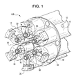
- FIG. 1 shows a diagrammatical representation of a plurality of pulse detonation engines and a valve control device in accordance with an embodiment of the present invention
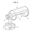
- FIG. 2 shows a diagrammatical representation of a valve timing device in accordance with the embodiment of the present invention shown in FIG. 1 ;
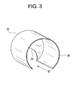
- FIG. 3 shows a diagrammatical representation of a stator device in accordance with the embodiment of the present invention shown in FIG. 1 ;
- FIG. 4 shows a diagrammatical representation of a timing method used for the embodiment of the present invention shown in FIG. 1 ;
- FIG. 5 shows a diagrammatical representation of the embodiment shown in FIG. 1 , during operation
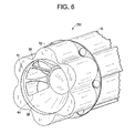
- FIG. 6 shows a diagrammatical representation of a plurality of pulse detonation engines and a valve control timing device in accordance with an additional embodiment of the present invention
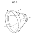
- FIG. 7 shows a diagrammatical representation of a valve timing device in accordance with the embodiment shown in FIG. 6 ;
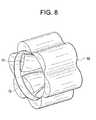
- FIG. 8 shows a diagrammatical representation of a stator device in accordance with the embodiment shown in FIG. 6 ;
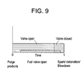
- FIG. 9 shows a graphical representation of the timing of air flow through the PDE that is controlled by the components of the present invention as it relates to a single detonation cycle.
- air is to include any all oxidizers, including but not limited to air, that can be used as a fuel oxidizer.
- FIG. 1 depicts an assembly 100 of a plurality of pulse detonation engines 10 in accordance with the present invention.
- Each of the engines 10 have a detonation chamber 12 which is downstream of the inlet portion 14 of the engine 10 .
- the inlet portion 14 of each of the engines 10 contains a valve timing device 16 , a stator device 18 , and a mounting bracket 20 . Further, each of the valve timing devices 16 contain a shaft 22 and a sprocket 24 .
- Each of the stator devices 18 contain an open portion 26 which allows air flow to enter the stator devices 18 and valve timing devices 16 during operation.
- the assembly 100 shown in FIG. 1 , is positioned downstream of a compressor in a typical gas turbine engine configuration. Further, the upstream portion of the assembly 100 is coupled to an air flow manifold structure which provides air flow to the pulse detonation engines 10 . It is contemplated that each pulse detonation engine 10 is coupled to the compressor stage (not shown) through a separate manifold structure, or that all engines 10 share a common supply manifold.
- Each of the valve timing devices 16 are rotated via the shaft 22 which has a sprocket 24 on and end thereof. Further, as shown in FIG. 1 , shafts 22 are supported by mounting brackets 20 .
- the present invention is not limited, in any way, with regard to the structure or configuration of the mounting brackets 20 depicted in FIG. 1 .
- the mounting brackets 20 are to be secured to the engine structure by any known conventional means.
- FIG. 2 shows a valve timing device 16 in accordance with an embodiment of the present invention.
- the timing device 16 is coupled to a shaft 22 which is supported by the mounting bracket 20 .
- a sprocket 24 At the end of the shaft 22 is a sprocket 24 .
- the timing device contains a blocking portion 28 and a slot portion 30 .
- the air flow from the compressor stage (not shown) enters the detonation chamber 12 when the slot portion 30 rotates to allow the air flow to enter the chamber 12 .
- Air flow is then blocked by the blocking portion 28 , when the blocking portion 28 rotates to block the air flow from entering the detonation chamber 12 .
- sprocket 24 Although the use of a sprocket 24 is shown with respect to the above embodiment, the present invention is not limited in this regard. It is contemplated that any known and conventional means to impart rotation or movement may be used.
- the present invention is not limited to having a single blocking portion 28 and slot portion 30 on the timing valve 16 .
- the timing valve 16 may have more than one blocking portions 28 (for example two) which are separated from each other by slot portions. Such a configuration will increase the overall frequency of operation while keeping the rotation rate the same.
- FIG. 2 shows the openings to be essentially rectangular in shape
- the present invention is not limited in this way. It is contemplated that the openings and/or blocking portion be tapered or angled (or have any other geometric shape) to optimize performance of the device. By tapering or angling the openings, the amount of air flow can be regulated or controlled depending on the desired characteristics and performance
- FIG. 3 shows a stator device 18 in accordance with an embodiment of the present invention.
- the forward most end of the stator device has an open portion 26 which allows air flow to enter the volume of the timing device 16 and stator device 18 .
- the size and shape of the open portion 26 is to control the amount of air flow to ensure the desired performance and operation. Further, the open portion 26 is to be of a sufficient size to allow the shaft 22 to pass through.
- the stator device 18 also has a wall portion 34 and a slot portion 32 . During operation, the air flow passes through the slot portion 32 into the detonation chamber 12 .
- the timing device 16 rotates partially within the stator device 18 . In an alternative embodiment of the present invention, this may be reversed.
- FIG. 4 shows an embodiment of a valve timing mechanism for the inlet air management system of the present invention.
- the view in this figure is the forward most end view of the assembly 100 .
- six pulse detonation engines 10 are shown, the present invention is not limited to this number, and although they are shown in a symmetrical circular patter, again the present invention is not limited to this, as the engines 10 can be distributed in any pattern or configuration.
- the sprockets 24 are engaged with a belts 40 , where the belts are driven by motors 42 .
- the motors 42 drive the belts 40
- each of the sprockets 24 are rotated, thus rotating the shafts 22 and the timing devices 16 .
- the motors can be operated at different speeds so that the operational frequency of the respective engines 10 are different. Additionally, this embodiment allows some of the engines 10 to be operated while the others are not, depending on the operational parameters. Further, the motors 42 can operate at the same speed as each other so as to ensure that the operational frequency of all of the engines 10 is the same.
- all of the sprockets 24 are coupled to the same belt 40 .
- all of the timing devices 16 are rotated at the same rate.
- the sprockets 24 can be made of various sizes so as to adjust the rotation rates of the respective timing devices. Namely, by using sprockets 24 of different sizes the respective rotational rates of the timing devices will be different even though the motor 42 is providing a constant speed.
- At least one of the motors 42 is a variable speed motor, which allows the rotational speed of the timing devices 16 (driven by that motor) to be adjusted based on the operational requirements and parameters.
- each of the respective engines 10 is coupled to its own individual motor 42 and belt 40 .
- each of the motors 42 can be operated at the same speed, or can be operated at varying speeds so as to provide for asynchronous operation of the engines 10 .
- each of the engines 10 may have the same operational frequency (for example 100 Hz) but are configured such that they are not pulsing at the same time. This is accomplished by having the timing devices 16 of respective engines 10 having different starting orientations such that even though they share the same rotational rate as the other engines 10 , the engines 10 respective operations (i.e. pulse detonations) are not occurring simultaneously.
- the motors 42 may be variable speed motors such that the operation of each respective engine 10 can be varied based on operational characteristics and parameters.
- FIG. 5 depicts a cross-section of an engine 10 in accordance with the embodiment of the present invention discussed with regard to FIGS. 1 through 4 .
- the stator device 18 and timing device 16 are positioned off-center with respect to the centerline of the engine 10 and the detonation chamber 12 . This is done to allow for the efficient flow of air from the stator and timing devices into the chamber 12 based on the configuration of the devices shown in FIGS. 2 and 3 .
- the present invention is not limited to this configuration and it is contemplated that additional embodiments of the stator and timing devices can be used which allows for similar operation.
- the respective opening portions of the timing and stator devices be on the downstream end wall of each of these components, such that the devices can be positioned on the centerline of the detonation chamber.
- the present invention is not limited by the physical structure of the devices or their relative positioning with regard to the detonation chamber.
- the timing device 16 rotates. This allows the open portion 30 of the timing device 16 to communicate with the open portion 32 of the stator device 18 as the rotation occurs. This permits the air flow F to pass from the devices to the detonation chamber 12 . Then as the blocking portion 28 of the timing device 16 passes by the opening 32 of the stator device 18 , the air flow F is temporarily blocked from entering the detonation chamber.
- the size of the respective open portions ( 30 of the timing device 16 , and 32 of the stator device 18 ) are determined to optimize operation of the engine 10 .
- the opening 30 of the timing device 16 should be sufficient to allow the air flow F to sufficiently form an air buffer with any residual post-detonation products within the chamber 12 and refill the chamber 12 with the necessary amount of air flow for the next detonation.
- the assembly 200 includes a plurality of pulse detonation engines 10 which are configured in a similar fashion to that described with regard to FIG. 1 . Because their respective structure is similar, a detailed discussion of the engines 10 will not be repeated at this point.
- a single valve timing device 60 and a single stator device 62 are used for the plurality of engines 10 .
- the stator device 62 is secured to the inlet portion of the engines 10 .
- the present invention is not limited by the means of securing the stator device 62 to the engines.
- Within the stator device 62 are a plurality of channels 70 , which are configured so as to communicate with the respective inlet portions of the engines 10 . This ensures that air flow will pass along the channels 70 to the respective engines 10 , for engine operation.
- the shape and geometry of the channels 70 are such that operational efficiency and performance are optimized.
- valve timing device 60 Within an opening 72 of the stator device 62 is a valve timing device 60 .
- the valve timing device 60 rotates about an axis which corresponds to a centerline of the assembly 200 .
- the valve timing device 60 has a plurality of openings 64 which allow the air flow to pass through to the channels 70 , and ultimately the engines 10 , for operation.
- the openings 64 are separated by support struts 66 , which provide for structural integrity of the device 60 .
- the embodiment shown in FIGS. 6 and 7 has three openings 64 and two support struts 66 .
- the present invention is not limited to this embodiment.
- an embodiment of the present invention can have a single opening, two openings, or more than three, to provide the necessary air flow to each of the engines 10 .
- another embodiment of the present invention has openings which are positioned 180 degrees from each other on the device 60 . This embodiment allows for the simultaneous operation of engines 10 which are opposite each other, as the valve timing device 60 rotates.
- valve timing device 60 is conical in shape.
- the present invention is not limited to this geometry.
- the centerline of the valve timing device 60 and stator device 62 is coincident with the centerline of the assembly 200 .
- the pulse detonation system may be fueled either upstream, downstream, or from within the valve timing or stator devices.
- the valve timing device 60 includes a drive connection portion 68 ( FIG. 7 ).
- a motor (not shown) is either coupled directly or via a drive shaft or mechanism to impart rotation on the timing device 60 .
- the motor is a variable speed motor to control the timing of the detonations and operation of the engines.
- the valve timing device may be driven by a belt or similar mechanism, as shown in FIG. 4 .
- a flange (or similar structure) may extend from the upstream portion of the valve timing device 60 , such that a belt may provide the necessary rotation.
- FIG. 9 A diagrammatical representation of this timing is shown in FIG. 9 , For the purposes of simplicity the time is shown from 0 to 1, with no units (i.e. seconds, ms, etc.) The selection of 0 to 1 is intended to merely reflect a single cycle of the device.
- the blocking portion 28 of the timing device 16 blocks the opening 30 of the stator device 18 and the fuel injection ends. Although it is shown in this figure that the fuel injection ends after the air flow is blocked, the present invention is not limited to this embodiment. Following these events, and when the opening 32 of the stator device 18 is blocked the spark/detonation occurs. Thus, any forward propagating pressure wave is blocked from entering the devices (and going further upstream). Thus damage to any upstream components is avoided.
- the opening 32 of the stator device 18 is completely blocked by the blocking portion 28 when detonation occurs.
- the present invention is not limited to this embodiment, and it is contemplated that the opening 32 be nearly closed when detonation begins and be fully closed when the main bulk of the forward propagating pressure wave reaches the devices.
- the timing of the operation, and the overall sizing of the components are selected to avoid the forward propagation of any significant or appreciable amount of any pressure wave generated from the detonation process. This will protect any upstream components from high pressure waves generated by the pulse detonation process
- the present invention has been discussed above specifically with respect to aircraft applications, the present invention is not limited to this and can be in any similar detonation/deflagration device in which the minimization of forward propagating pressure waves is desired.
Landscapes
- Engineering & Computer Science (AREA)
- Chemical & Material Sciences (AREA)
- Combustion & Propulsion (AREA)
- Mechanical Engineering (AREA)
- General Engineering & Computer Science (AREA)
- Fluidized-Bed Combustion And Resonant Combustion (AREA)
Abstract
Description
- This invention relates to pulse detonation systems, and more particularly, to an inlet airflow management system for use on a pulse detonation engine for supersonic applications.
- With the recent development of pulse detonation combustors (PDCs) and engines (PDEs), various efforts have been underway to use PDC/Es in practical applications, such as combustors for aircraft engines. Just as with any normal air breathing engine, inlet stability is an important aspect of maintaining proper operation of a pulse detonation engine. This is particularly true in applications with multiple combustors with a common inlet, where it is important to minimize or eliminate disruptions to the inlet. Such disruptions include pressure fluctuations, which have the potential to “un-start” or stall the airflow through the inlet, compressor, or other upstream devices.
- These problems are particularly prevalent in pulse detonation engines which use open inlet tubes. During operation, PDE's create a high pressure detonation wave used for propulsion (as it exits the PDE). However, it has also been observed that a forward propagating pressure wave, which may contain fuel-air reaction products, is generated. Because the pulse detonation process is a high pressure rise process, these forward propagating pressure waves may provide enough perturbation to “un-start” the PDE inlet, as well as expose some of the upstream components to high pressure pulses, which could cause damage to these components.
- Thus, it is desirable to provide some means or methodology to block these forward propagating pressure waves. Some efforts have been made to accomplish this by using conventional air flow valves. However, because of the operational pressures and frequencies involved (which can be as high as 100 Hz), such devices have had limited or no success.
- Therefore, there exists a need to block any upstream pressure waves generated by a detonation, using a relatively simple and robust system. It is noted that although the expression “pulse detonation engine” is used herein, this term is intended to describe all combustion type devices employing pulse detonation technology, including but not limited to pulse detonation combustors, and the like.
- In an embodiment of the invention, a pulse detonation engine (PDE) comprises a mechanically driven timing rotor in a cone or device configuration. The cone (or device) configuration is designed with a specially designed slot or slots, and blockages to open and close the pulse detonation engine at the appropriate times during the pulse detonation cycle.
- At the upstream most portion of the pulse detonation engine (upstream of the detonation chamber), a valve timing device is made rotatable around a central axis. The device contains a blocking portion and a slot portion, and as the device is rotated the detonation chamber of the PDE is either closed or opened to the upstream portions of the system. The device may be coupled to a sprocket or sprocket coupled to a drive motor or device, or may be directly driven by the motor, to provide the necessary rotation. The rotational speed of the timing device can be adjustable to coincide with operational changes in the PDE.
- At the forward end of the PDE the valve timing device is mated with a stationary slotted geometry herein referred to as a stator device, which is open to detonation chamber of the PDE. The configuration and mating of the valve timing and stator devices are such that as the valve timing device is rotated the detonation chamber is opened and closed to the upstream portions of the system.
- The present invention also contains an embodiment where a plurality of pulse detonation engines are coupled to each other and the valve timing devices of each respective PDE are rotated together or separately.
- A further embodiment of the present invention, is one where a plurality of pulse detonation engines are coupled to each other and a single valve timing device rotates along the centerline of the plurality of PDEs.
- This invention is not limited to the configuration of one or a plurality of PDEs connected to a single timing device. Alternatively, a single timing device may be connected to each PDE and rotated together or separately.
- As used herein, a “pulse detonation combustor” PDC (also including PDEs) is understood to mean any device or system that produces both a pressure rise and velocity increase from a series of repeating detonations or quasi-detonations within the device. A “quasi-detonation” is a supersonic turbulent combustion process that produces a pressure rise and velocity increase higher than the pressure rise and velocity increase produced by a deflagration wave. Embodiments of PDCs (and PDEs) include a means of igniting a fuelloxidizer mixture, for example a fuel/air mixture, and a detonation chamber, in which pressure wave fronts initiated by the ignition process coalesce to produce a detonation wave. Each detonation or quasi-detonation is initiated either by external ignition, such as spark discharge or laser pulse, or by gas dynamic processes, such as shock focusing, auto ignition or by another detonation (i.e. cross-fire).
- The advantages, nature and various additional features of the invention will appear more fully upon consideration of the illustrative embodiment of the invention which is schematically set forth in the figures, in which:
-
FIG. 1 shows a diagrammatical representation of a plurality of pulse detonation engines and a valve control device in accordance with an embodiment of the present invention; -
FIG. 2 shows a diagrammatical representation of a valve timing device in accordance with the embodiment of the present invention shown inFIG. 1 ; -
FIG. 3 shows a diagrammatical representation of a stator device in accordance with the embodiment of the present invention shown inFIG. 1 ; -
FIG. 4 shows a diagrammatical representation of a timing method used for the embodiment of the present invention shown inFIG. 1 ; -
FIG. 5 shows a diagrammatical representation of the embodiment shown inFIG. 1 , during operation; -
FIG. 6 shows a diagrammatical representation of a plurality of pulse detonation engines and a valve control timing device in accordance with an additional embodiment of the present invention; -
FIG. 7 shows a diagrammatical representation of a valve timing device in accordance with the embodiment shown inFIG. 6 ; -
FIG. 8 shows a diagrammatical representation of a stator device in accordance with the embodiment shown inFIG. 6 ; and -
FIG. 9 shows a graphical representation of the timing of air flow through the PDE that is controlled by the components of the present invention as it relates to a single detonation cycle. - The present invention will be explained in further detail by making reference to the accompanying drawings, which do not limit the scope of the invention in any way.
- As used herein, the term “air” is to include any all oxidizers, including but not limited to air, that can be used as a fuel oxidizer.
-
FIG. 1 depicts anassembly 100 of a plurality ofpulse detonation engines 10 in accordance with the present invention. Each of theengines 10 have adetonation chamber 12 which is downstream of theinlet portion 14 of theengine 10. Theinlet portion 14 of each of theengines 10 contains avalve timing device 16, astator device 18, and amounting bracket 20. Further, each of thevalve timing devices 16 contain ashaft 22 and asprocket 24. - Each of the
stator devices 18 contain anopen portion 26 which allows air flow to enter thestator devices 18 andvalve timing devices 16 during operation. Although not shown, it is contemplated that theassembly 100, shown inFIG. 1 , is positioned downstream of a compressor in a typical gas turbine engine configuration. Further, the upstream portion of theassembly 100 is coupled to an air flow manifold structure which provides air flow to thepulse detonation engines 10. It is contemplated that eachpulse detonation engine 10 is coupled to the compressor stage (not shown) through a separate manifold structure, or that allengines 10 share a common supply manifold. - Each of the
valve timing devices 16 are rotated via theshaft 22 which has asprocket 24 on and end thereof. Further, as shown inFIG. 1 ,shafts 22 are supported bymounting brackets 20. The present invention is not limited, in any way, with regard to the structure or configuration of themounting brackets 20 depicted inFIG. 1 . Themounting brackets 20 are to be secured to the engine structure by any known conventional means. -
FIG. 2 shows avalve timing device 16 in accordance with an embodiment of the present invention. Thetiming device 16 is coupled to ashaft 22 which is supported by themounting bracket 20. At the end of theshaft 22 is asprocket 24, In an exemplary embodiment of the present invention, the timing device contains a blockingportion 28 and aslot portion 30. During operation, as thetiming device 16 is rotated by theshaft 22, the air flow from the compressor stage (not shown) enters thedetonation chamber 12 when theslot portion 30 rotates to allow the air flow to enter thechamber 12. Air flow is then blocked by the blockingportion 28, when the blockingportion 28 rotates to block the air flow from entering thedetonation chamber 12. Such an operation avoids the need for having complicated air flow control equipment to control air flow from the compressor stage (not shown). In fact, air flow from the compressor stage can be maintained constant, resulting in relatively minor pressure rises as the blockingportion 28 blocks air flow from entering thedetonation chambers 12. These pressure rises are relatively small when compared to the pressure rises which may be experienced due to forward propagating pressure waves from the pulse detonation process. - Although the use of a
sprocket 24 is shown with respect to the above embodiment, the present invention is not limited in this regard. It is contemplated that any known and conventional means to impart rotation or movement may be used. - Additionally, the present invention is not limited to having a
single blocking portion 28 andslot portion 30 on thetiming valve 16. Specifically, it is contemplated that thetiming valve 16 may have more than one blocking portions 28 (for example two) which are separated from each other by slot portions. Such a configuration will increase the overall frequency of operation while keeping the rotation rate the same. - Moreover, although
FIG. 2 (and the followingFIG. 3 ) shows the openings to be essentially rectangular in shape, the present invention is not limited in this way. It is contemplated that the openings and/or blocking portion be tapered or angled (or have any other geometric shape) to optimize performance of the device. By tapering or angling the openings, the amount of air flow can be regulated or controlled depending on the desired characteristics and performance -
FIG. 3 shows astator device 18 in accordance with an embodiment of the present invention. The forward most end of the stator device has anopen portion 26 which allows air flow to enter the volume of thetiming device 16 andstator device 18. The size and shape of theopen portion 26 is to control the amount of air flow to ensure the desired performance and operation. Further, theopen portion 26 is to be of a sufficient size to allow theshaft 22 to pass through. Thestator device 18 also has awall portion 34 and aslot portion 32. During operation, the air flow passes through theslot portion 32 into thedetonation chamber 12. In the assembly of the present invention, thetiming device 16 rotates partially within thestator device 18. In an alternative embodiment of the present invention, this may be reversed. -
FIG. 4 shows an embodiment of a valve timing mechanism for the inlet air management system of the present invention. The view in this figure is the forward most end view of theassembly 100. Further, although sixpulse detonation engines 10 are shown, the present invention is not limited to this number, and although they are shown in a symmetrical circular patter, again the present invention is not limited to this, as theengines 10 can be distributed in any pattern or configuration. - In
FIG. 4 , thesprockets 24 are engaged with abelts 40, where the belts are driven bymotors 42. As themotors 42 drive thebelts 40, each of thesprockets 24 are rotated, thus rotating theshafts 22 and thetiming devices 16. In this embodiment, the motors can be operated at different speeds so that the operational frequency of therespective engines 10 are different. Additionally, this embodiment allows some of theengines 10 to be operated while the others are not, depending on the operational parameters. Further, themotors 42 can operate at the same speed as each other so as to ensure that the operational frequency of all of theengines 10 is the same. - In an alternative embodiment, all of the
sprockets 24 are coupled to thesame belt 40. In this embodiment, all of thetiming devices 16 are rotated at the same rate. It is also contemplated that thesprockets 24 can be made of various sizes so as to adjust the rotation rates of the respective timing devices. Namely, by usingsprockets 24 of different sizes the respective rotational rates of the timing devices will be different even though themotor 42 is providing a constant speed. - In a further alternative embodiment, at least one of the
motors 42 is a variable speed motor, which allows the rotational speed of the timing devices 16 (driven by that motor) to be adjusted based on the operational requirements and parameters. - Additionally it is noted that although this embodiment is shown with two
motors 42, it is contemplated that more than twomotors 42 can be used, such that the motor to engine ratio is less than that shown inFIG. 4 . - In a further alternative to the present invention, each of the
respective engines 10 is coupled to its ownindividual motor 42 andbelt 40. In this embodiment, each of themotors 42 can be operated at the same speed, or can be operated at varying speeds so as to provide for asynchronous operation of theengines 10. - Additionally, in this embodiment (as also in the embodiments discussed above) each of the
engines 10 may have the same operational frequency (for example 100 Hz) but are configured such that they are not pulsing at the same time. This is accomplished by having the timingdevices 16 ofrespective engines 10 having different starting orientations such that even though they share the same rotational rate as theother engines 10, theengines 10 respective operations (i.e. pulse detonations) are not occurring simultaneously. Further, as with the previous embodiments, themotors 42 may be variable speed motors such that the operation of eachrespective engine 10 can be varied based on operational characteristics and parameters. -
FIG. 5 depicts a cross-section of anengine 10 in accordance with the embodiment of the present invention discussed with regard toFIGS. 1 through 4 . As shown in this figure, thestator device 18 andtiming device 16 are positioned off-center with respect to the centerline of theengine 10 and thedetonation chamber 12. This is done to allow for the efficient flow of air from the stator and timing devices into thechamber 12 based on the configuration of the devices shown inFIGS. 2 and 3 . However, the present invention is not limited to this configuration and it is contemplated that additional embodiments of the stator and timing devices can be used which allows for similar operation. For example, it is contemplated that the respective opening portions of the timing and stator devices be on the downstream end wall of each of these components, such that the devices can be positioned on the centerline of the detonation chamber. In any event, the present invention is not limited by the physical structure of the devices or their relative positioning with regard to the detonation chamber. - As shown in
FIG. 5 , as theshaft 22 rotates thetiming device 16 rotates. This allows theopen portion 30 of thetiming device 16 to communicate with theopen portion 32 of thestator device 18 as the rotation occurs. This permits the air flow F to pass from the devices to thedetonation chamber 12. Then as the blockingportion 28 of thetiming device 16 passes by theopening 32 of thestator device 18, the air flow F is temporarily blocked from entering the detonation chamber. - The size of the respective open portions (30 of the
timing device engine 10. For example, in an embodiment of the invention, theopening 30 of thetiming device 16 should be sufficient to allow the air flow F to sufficiently form an air buffer with any residual post-detonation products within thechamber 12 and refill thechamber 12 with the necessary amount of air flow for the next detonation. - Turning now to
FIGS. 6 , 7 and 8, an additional exemplary embodiment of the present invention is shown. As withFIG. 1 , theassembly 200 includes a plurality ofpulse detonation engines 10 which are configured in a similar fashion to that described with regard toFIG. 1 . Because their respective structure is similar, a detailed discussion of theengines 10 will not be repeated at this point. In this embodiment, a singlevalve timing device 60 and asingle stator device 62 are used for the plurality ofengines 10. - In this embodiment, the
stator device 62 is secured to the inlet portion of theengines 10. The present invention is not limited by the means of securing thestator device 62 to the engines. Within thestator device 62 are a plurality ofchannels 70, which are configured so as to communicate with the respective inlet portions of theengines 10. This ensures that air flow will pass along thechannels 70 to therespective engines 10, for engine operation. The shape and geometry of thechannels 70 are such that operational efficiency and performance are optimized. - Within an
opening 72 of thestator device 62 is avalve timing device 60. Thevalve timing device 60 rotates about an axis which corresponds to a centerline of theassembly 200. As shown inFIG. 7 , thevalve timing device 60 has a plurality ofopenings 64 which allow the air flow to pass through to thechannels 70, and ultimately theengines 10, for operation. As shown, theopenings 64 are separated by support struts 66, which provide for structural integrity of thedevice 60. The embodiment shown inFIGS. 6 and 7 has threeopenings 64 and two support struts 66. However, the present invention is not limited to this embodiment. Namely, an embodiment of the present invention can have a single opening, two openings, or more than three, to provide the necessary air flow to each of theengines 10. Moreover, another embodiment of the present invention has openings which are positioned 180 degrees from each other on thedevice 60. This embodiment allows for the simultaneous operation ofengines 10 which are opposite each other, as thevalve timing device 60 rotates. - In
FIGS. 6 and 7 , thevalve timing device 60 is conical in shape. However, the present invention is not limited to this geometry. Further, unlike the embodiment shown inFIGS. 1 to 4 , in this embodiment the centerline of thevalve timing device 60 andstator device 62 is coincident with the centerline of theassembly 200. - Further, the pulse detonation system may be fueled either upstream, downstream, or from within the valve timing or stator devices.
- The
valve timing device 60 includes a drive connection portion 68 (FIG. 7 ). In this embodiment, a motor (not shown) is either coupled directly or via a drive shaft or mechanism to impart rotation on thetiming device 60. Again, the motor is a variable speed motor to control the timing of the detonations and operation of the engines. In an alternative embodiment, the valve timing device may be driven by a belt or similar mechanism, as shown inFIG. 4 . In this configuration, a flange (or similar structure) may extend from the upstream portion of thevalve timing device 60, such that a belt may provide the necessary rotation. - A diagrammatical representation of this timing is shown in
FIG. 9 , For the purposes of simplicity the time is shown from 0 to 1, with no units (i.e. seconds, ms, etc.) The selection of 0 to 1 is intended to merely reflect a single cycle of the device. At time 0 the valve system opens. This is when theopening 30 of thetiming device 16 begins communication with theopening 32 of thestator device 18. As these openings communicate with each other, the air flow F begins to purge thedetonation chamber 12 of the engine. At some point after T=0, the purge process ends and fuel is injected into thechamber 12 to mix with the air flow F. It is noted that the present invention is not limited in any way with respect to the fuel injection and/or spark initiation methodology used, as any known methods may be used and employed. - At some point after fuel fill begins the blocking
portion 28 of thetiming device 16 blocks theopening 30 of thestator device 18 and the fuel injection ends. Although it is shown in this figure that the fuel injection ends after the air flow is blocked, the present invention is not limited to this embodiment. Following these events, and when theopening 32 of thestator device 18 is blocked the spark/detonation occurs. Thus, any forward propagating pressure wave is blocked from entering the devices (and going further upstream). Thus damage to any upstream components is avoided. - In the embodiment discussed above, the
opening 32 of thestator device 18 is completely blocked by the blockingportion 28 when detonation occurs. However, the present invention is not limited to this embodiment, and it is contemplated that theopening 32 be nearly closed when detonation begins and be fully closed when the main bulk of the forward propagating pressure wave reaches the devices. In any event, the timing of the operation, and the overall sizing of the components are selected to avoid the forward propagation of any significant or appreciable amount of any pressure wave generated from the detonation process. This will protect any upstream components from high pressure waves generated by the pulse detonation process - It is noted that although the present invention has been discussed above specifically with respect to aircraft applications, the present invention is not limited to this and can be in any similar detonation/deflagration device in which the minimization of forward propagating pressure waves is desired.
- While the invention has been described in terms of various specific embodiments, those skilled in the art will recognize that the invention can be practiced with modification within the spirit and scope of the claims.
Claims (34)
Priority Applications (1)
| Application Number | Priority Date | Filing Date | Title |
|---|---|---|---|
| US11/554,824 US7891164B2 (en) | 2006-10-31 | 2006-10-31 | Inlet airflow management system for a pulse detonation engine for supersonic applications |
Applications Claiming Priority (1)
| Application Number | Priority Date | Filing Date | Title |
|---|---|---|---|
| US11/554,824 US7891164B2 (en) | 2006-10-31 | 2006-10-31 | Inlet airflow management system for a pulse detonation engine for supersonic applications |
Publications (2)
| Publication Number | Publication Date |
|---|---|
| US20080098710A1 true US20080098710A1 (en) | 2008-05-01 |
| US7891164B2 US7891164B2 (en) | 2011-02-22 |
Family
ID=39328498
Family Applications (1)
| Application Number | Title | Priority Date | Filing Date |
|---|---|---|---|
| US11/554,824 Expired - Fee Related US7891164B2 (en) | 2006-10-31 | 2006-10-31 | Inlet airflow management system for a pulse detonation engine for supersonic applications |
Country Status (1)
| Country | Link |
|---|---|
| US (1) | US7891164B2 (en) |
Cited By (7)
| Publication number | Priority date | Publication date | Assignee | Title |
|---|---|---|---|---|
| US20090139199A1 (en) * | 2007-11-15 | 2009-06-04 | General Electric Company | Pulse detonation combustor valve for high temperature and high pressure operation |
| US20090266047A1 (en) * | 2007-11-15 | 2009-10-29 | General Electric Company | Multi-tube, can-annular pulse detonation combustor based engine with tangentially and longitudinally angled pulse detonation combustors |
| US20100242436A1 (en) * | 2009-03-31 | 2010-09-30 | General Electric Company | Modulation of inlet mass flow and resonance for a multi-tube pulse detonation engine system using phase shifted operation and detuning |
| US20110146285A1 (en) * | 2009-12-17 | 2011-06-23 | General Electric Company | Pulse detonation system with fuel lean inlet region |
| US20120017563A1 (en) * | 2009-01-27 | 2012-01-26 | Michel Aguilar | Jet engine, in particular a jet engine for an aircraft |
| US8341932B2 (en) | 2009-03-19 | 2013-01-01 | General Electric Company | Rotary air valve firing patterns for resonance detuning |
| CN118729326A (en) * | 2024-07-08 | 2024-10-01 | 南京理工大学 | A rotating detonation combustion chamber with variable flow resistance |
Families Citing this family (7)
| Publication number | Priority date | Publication date | Assignee | Title |
|---|---|---|---|---|
| US7531908B2 (en) * | 2002-10-02 | 2009-05-12 | University Of South Florida | Apparatus that harnesses explosive force to do work |
| EP2971514B1 (en) | 2013-03-15 | 2020-07-22 | Rolls-Royce North American Technologies, Inc. | Continuous detonation combustion engine and system |
| EP3062023A1 (en) | 2015-02-20 | 2016-08-31 | Rolls-Royce North American Technologies, Inc. | Wave rotor with piston assembly |
| US10393383B2 (en) | 2015-03-13 | 2019-08-27 | Rolls-Royce North American Technologies Inc. | Variable port assemblies for wave rotors |
| CN105840317B (en) * | 2016-03-29 | 2017-08-22 | 朱超华 | Rotary combined valve and pulse-knocking formula engine |
| US11674476B2 (en) | 2017-06-09 | 2023-06-13 | General Electric Company | Multiple chamber rotating detonation combustor |
| US10641169B2 (en) | 2017-06-09 | 2020-05-05 | General Electric Company | Hybrid combustor assembly and method of operation |
Citations (9)
| Publication number | Priority date | Publication date | Assignee | Title |
|---|---|---|---|---|
| US5345758A (en) * | 1993-04-14 | 1994-09-13 | Adroit Systems, Inc. | Rotary valve multiple combustor pulse detonation engine |
| US6062018A (en) * | 1993-04-14 | 2000-05-16 | Adroit Systems, Inc. | Pulse detonation electrical power generation apparatus with water injection |
| US6505462B2 (en) * | 2001-03-29 | 2003-01-14 | General Electric Company | Rotary valve for pulse detonation engines |
| US6637187B2 (en) * | 2000-09-08 | 2003-10-28 | Techland Research, Inc. | Rotary inlet flow controller for pulse detonation combustion engines |
| US6889505B2 (en) * | 2003-04-02 | 2005-05-10 | General Electric Company | Pulse detonation system for a gas turbine engine |
| US7124573B2 (en) * | 2004-03-18 | 2006-10-24 | General Electric Company | Rotary pulse detonation system with aerodynamic detonation passages for use in a gas turbine engine |
| US7228683B2 (en) * | 2004-07-21 | 2007-06-12 | General Electric Company | Methods and apparatus for generating gas turbine engine thrust using a pulse detonator |
| US7520123B2 (en) * | 2005-05-12 | 2009-04-21 | Lockheed Martin Corporation | Mixing-enhancement inserts for pulse detonation chambers |
| US20090120059A1 (en) * | 2005-11-16 | 2009-05-14 | Sanders Bobby W | Seal for pulse detonation engine |
-
2006
- 2006-10-31 US US11/554,824 patent/US7891164B2/en not_active Expired - Fee Related
Patent Citations (10)
| Publication number | Priority date | Publication date | Assignee | Title |
|---|---|---|---|---|
| US5345758A (en) * | 1993-04-14 | 1994-09-13 | Adroit Systems, Inc. | Rotary valve multiple combustor pulse detonation engine |
| US5513489A (en) * | 1993-04-14 | 1996-05-07 | Adroit Systems, Inc. | Rotary valve multiple combustor pulse detonation engine |
| US6062018A (en) * | 1993-04-14 | 2000-05-16 | Adroit Systems, Inc. | Pulse detonation electrical power generation apparatus with water injection |
| US6637187B2 (en) * | 2000-09-08 | 2003-10-28 | Techland Research, Inc. | Rotary inlet flow controller for pulse detonation combustion engines |
| US6505462B2 (en) * | 2001-03-29 | 2003-01-14 | General Electric Company | Rotary valve for pulse detonation engines |
| US6889505B2 (en) * | 2003-04-02 | 2005-05-10 | General Electric Company | Pulse detonation system for a gas turbine engine |
| US7124573B2 (en) * | 2004-03-18 | 2006-10-24 | General Electric Company | Rotary pulse detonation system with aerodynamic detonation passages for use in a gas turbine engine |
| US7228683B2 (en) * | 2004-07-21 | 2007-06-12 | General Electric Company | Methods and apparatus for generating gas turbine engine thrust using a pulse detonator |
| US7520123B2 (en) * | 2005-05-12 | 2009-04-21 | Lockheed Martin Corporation | Mixing-enhancement inserts for pulse detonation chambers |
| US20090120059A1 (en) * | 2005-11-16 | 2009-05-14 | Sanders Bobby W | Seal for pulse detonation engine |
Cited By (9)
| Publication number | Priority date | Publication date | Assignee | Title |
|---|---|---|---|---|
| US20090139199A1 (en) * | 2007-11-15 | 2009-06-04 | General Electric Company | Pulse detonation combustor valve for high temperature and high pressure operation |
| US20090139203A1 (en) * | 2007-11-15 | 2009-06-04 | General Electric Company | Method and apparatus for tailoring the equivalence ratio in a valved pulse detonation combustor |
| US20090266047A1 (en) * | 2007-11-15 | 2009-10-29 | General Electric Company | Multi-tube, can-annular pulse detonation combustor based engine with tangentially and longitudinally angled pulse detonation combustors |
| US20120017563A1 (en) * | 2009-01-27 | 2012-01-26 | Michel Aguilar | Jet engine, in particular a jet engine for an aircraft |
| US8925296B2 (en) * | 2009-01-27 | 2015-01-06 | Michel Aguilar | Jet engine, in particular a jet engine for an aircraft |
| US8341932B2 (en) | 2009-03-19 | 2013-01-01 | General Electric Company | Rotary air valve firing patterns for resonance detuning |
| US20100242436A1 (en) * | 2009-03-31 | 2010-09-30 | General Electric Company | Modulation of inlet mass flow and resonance for a multi-tube pulse detonation engine system using phase shifted operation and detuning |
| US20110146285A1 (en) * | 2009-12-17 | 2011-06-23 | General Electric Company | Pulse detonation system with fuel lean inlet region |
| CN118729326A (en) * | 2024-07-08 | 2024-10-01 | 南京理工大学 | A rotating detonation combustion chamber with variable flow resistance |
Also Published As
| Publication number | Publication date |
|---|---|
| US7891164B2 (en) | 2011-02-22 |
Similar Documents
| Publication | Publication Date | Title |
|---|---|---|
| US7891164B2 (en) | Inlet airflow management system for a pulse detonation engine for supersonic applications | |
| CN109028142B (en) | Propulsion system and method of operating the same | |
| US20090139199A1 (en) | Pulse detonation combustor valve for high temperature and high pressure operation | |
| US11674476B2 (en) | Multiple chamber rotating detonation combustor | |
| CN109028149B (en) | Variable geometry rotary detonation combustor and method of operating same | |
| US8341932B2 (en) | Rotary air valve firing patterns for resonance detuning | |
| US7526912B2 (en) | Pulse detonation engines and components thereof | |
| JP5650910B2 (en) | Hybrid engine for power generation based on ground-mounted simple cycle pulse detonation combustor | |
| US7950219B2 (en) | Dual mode combustion operation of a pulse detonation combustor in a hybrid engine | |
| US6439503B1 (en) | Pulse detonation cluster engine | |
| US9726080B2 (en) | Helical cross flow (HCF) pulse detonation engine | |
| US20110146232A1 (en) | Control system for a pulse detonation turbine engine | |
| US11572840B2 (en) | Multi-mode combustion control for a rotating detonation combustion system | |
| EP2336523A2 (en) | Pulse detonation system with fuel lean inlet region | |
| US20180355792A1 (en) | Annular throats rotating detonation combustor | |
| US7614211B2 (en) | Swirling flows and swirler to enhance pulse detonation engine operation | |
| EP2472090A2 (en) | A gas engine turbine comprising a thrust augmentation system | |
| US7131260B2 (en) | Multiple detonation initiator for frequency multiplied pulsed detonation combustion | |
| US20100242436A1 (en) | Modulation of inlet mass flow and resonance for a multi-tube pulse detonation engine system using phase shifted operation and detuning | |
| US20080127630A1 (en) | Turbine for application to pulse detonation combustion system and engine containing the turbine |
Legal Events
| Date | Code | Title | Description |
|---|---|---|---|
| AS | Assignment |
Owner name: GENERAL ELECTRIC COMPANY, NEW YORK Free format text: ASSIGNMENT OF ASSIGNORS INTEREST;ASSIGNORS:JANSSEN, JONATHAN SEBASTIAN;TANGIRALA, VENKAT ESWARLU;DEAN, ANTHONY JOHN;AND OTHERS;REEL/FRAME:018459/0431;SIGNING DATES FROM 20061020 TO 20061023 |
|
| FEPP | Fee payment procedure |
Free format text: PAYOR NUMBER ASSIGNED (ORIGINAL EVENT CODE: ASPN); ENTITY STATUS OF PATENT OWNER: LARGE ENTITY |
|
| STCF | Information on status: patent grant |
Free format text: PATENTED CASE |
|
| CC | Certificate of correction | ||
| FPAY | Fee payment |
Year of fee payment: 4 |
|
| MAFP | Maintenance fee payment |
Free format text: PAYMENT OF MAINTENANCE FEE, 8TH YEAR, LARGE ENTITY (ORIGINAL EVENT CODE: M1552) Year of fee payment: 8 |
|
| FEPP | Fee payment procedure |
Free format text: MAINTENANCE FEE REMINDER MAILED (ORIGINAL EVENT CODE: REM.); ENTITY STATUS OF PATENT OWNER: LARGE ENTITY |
|
| LAPS | Lapse for failure to pay maintenance fees |
Free format text: PATENT EXPIRED FOR FAILURE TO PAY MAINTENANCE FEES (ORIGINAL EVENT CODE: EXP.); ENTITY STATUS OF PATENT OWNER: LARGE ENTITY |
|
| STCH | Information on status: patent discontinuation |
Free format text: PATENT EXPIRED DUE TO NONPAYMENT OF MAINTENANCE FEES UNDER 37 CFR 1.362 |
|
| FP | Lapsed due to failure to pay maintenance fee |
Effective date: 20230222 |