US20080098679A1 - Waterproof gate assembly structure - Google Patents
Waterproof gate assembly structure Download PDFInfo
- Publication number
- US20080098679A1 US20080098679A1 US11/589,306 US58930606A US2008098679A1 US 20080098679 A1 US20080098679 A1 US 20080098679A1 US 58930606 A US58930606 A US 58930606A US 2008098679 A1 US2008098679 A1 US 2008098679A1
- Authority
- US
- United States
- Prior art keywords
- inner casing
- sheathing layer
- inflatable inner
- assembly structure
- waterproof
- Prior art date
- Legal status (The legal status is an assumption and is not a legal conclusion. Google has not performed a legal analysis and makes no representation as to the accuracy of the status listed.)
- Abandoned
Links
- XEEYBQQBJWHFJM-UHFFFAOYSA-N Iron Chemical compound [Fe] XEEYBQQBJWHFJM-UHFFFAOYSA-N 0.000 claims abstract description 14
- 229910052742 iron Inorganic materials 0.000 claims abstract description 7
- 239000000463 material Substances 0.000 claims description 4
- 239000004033 plastic Substances 0.000 claims description 4
- 239000000835 fiber Substances 0.000 claims description 2
- 239000003566 sealing material Substances 0.000 description 3
- 239000007779 soft material Substances 0.000 description 3
- 238000000034 method Methods 0.000 description 1
- 238000012986 modification Methods 0.000 description 1
- 230000004048 modification Effects 0.000 description 1
Images


Classifications
-
- E—FIXED CONSTRUCTIONS
- E06—DOORS, WINDOWS, SHUTTERS, OR ROLLER BLINDS IN GENERAL; LADDERS
- E06B—FIXED OR MOVABLE CLOSURES FOR OPENINGS IN BUILDINGS, VEHICLES, FENCES OR LIKE ENCLOSURES IN GENERAL, e.g. DOORS, WINDOWS, BLINDS, GATES
- E06B9/00—Screening or protective devices for wall or similar openings, with or without operating or securing mechanisms; Closures of similar construction
- E06B9/02—Shutters, movable grilles, or other safety closing devices, e.g. against burglary
-
- E—FIXED CONSTRUCTIONS
- E02—HYDRAULIC ENGINEERING; FOUNDATIONS; SOIL SHIFTING
- E02B—HYDRAULIC ENGINEERING
- E02B7/00—Barrages or weirs; Layout, construction, methods of, or devices for, making same
- E02B7/20—Movable barrages; Lock or dry-dock gates
- E02B7/22—Stop log dams; Emergency gates
-
- E—FIXED CONSTRUCTIONS
- E02—HYDRAULIC ENGINEERING; FOUNDATIONS; SOIL SHIFTING
- E02B—HYDRAULIC ENGINEERING
- E02B7/00—Barrages or weirs; Layout, construction, methods of, or devices for, making same
- E02B7/20—Movable barrages; Lock or dry-dock gates
- E02B7/54—Sealings for gates
-
- E—FIXED CONSTRUCTIONS
- E06—DOORS, WINDOWS, SHUTTERS, OR ROLLER BLINDS IN GENERAL; LADDERS
- E06B—FIXED OR MOVABLE CLOSURES FOR OPENINGS IN BUILDINGS, VEHICLES, FENCES OR LIKE ENCLOSURES IN GENERAL, e.g. DOORS, WINDOWS, BLINDS, GATES
- E06B9/00—Screening or protective devices for wall or similar openings, with or without operating or securing mechanisms; Closures of similar construction
- E06B2009/007—Flood panels
Definitions
- the present invention relates to a waterproof gate assembly structure, and more particularly to a waterproof gate assembly structure, wherein one side of a sheathing layer of which is provided with locking elements to replace an inflatable inner casing installed inside the sheathing layer and provided with a nozzle, with the nozzle being extended outward to the sheathing layer, such that gas can be filled into the inflatable inner casing until it is full.
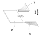
- a conventional waterproof gate is composed of locking grooves A 1 and a baffle A 2 , wherein the locking grooves A 1 should be first fixed at two sides of a wall A 3 respectively, such that when the gate is used, the baffle A 2 can be emplaced into the locking grooves A 1 .
- an effect of waterproof is not perfect.
- the primary object of present invention is to provide a waterproof gate assembly structure, wherein one side of a sheathing layer of which is provided with locking elements to replace an inflatable inner casing which is located inside the sheathing layer, and the inflatable inner casing is provided with a nozzle which is extended outward to the sheathing layer. Gas can be filled into the inflatable inner casing through the nozzle until it is full, so as to more tightly fill a space that has not been filled completely, thereby achieving a function of waterproof.
- FIG. 1 shows a perspective view of a conventional waterproof gate.
- FIG. 2 shows a schematic view of an embodiment of conventional waterproof gate.
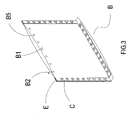
- FIG. 3 shows a perspective view of the present invention.
- FIG. 4 shows an exploded view of the present invention.
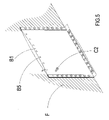
- FIG. 5 shows a schematic view of an embodiment of the present invention.
- FIG. 6 shows a second schematic view of an embodiment of the present invention.
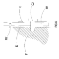
- FIG. 7 shows a third schematic view of an embodiment of the present invention.
- a waterproof gate assembly structure B of the present invention comprises a sheathing layer B 1 , a nozzle B 2 , iron pieces C, screw-holes C 1 , and fixing screws C 2 .
- An interior of the sheathing layer B 1 is installed with an inflatable inner casing D on which is provided with the nozzle B 2 being extended toward an exterior of the sheathing layer B 1 .
- Gas can be filled into the inflatable inner casing D through the nozzle B 2 until it is full, and a plurality of small holes B 4 is located at edges of two sides and a lower side of the sheathing layer B 1 , and is latched with boots B 3 , such that the small holes B 4 will not be damaged from a multiple time of usage.
- an upper side of the inflatable inner casing D is provided with a plurality of locking elements B 5 to provide for a replacement of the inflatable inner casing D.
- the iron pieces C should be used as a fixing medium.
- the iron pieces C are provided with the plural screw-holes C 1 which are corresponding to the small holes B 4 on the sheathing layer B 1 .
- the sheathing layer B 1 can be more rigidly fixed on the wall by using the iron pieces C and pads E, such that a function of waterproof can be more enhanced for the waterproof gate B.
- the pads E are placed between the sheathing layer B 1 and a wall F, such that the fixing screws C 2 are transfixed into the small holes B 4 , the screw-holes C 1 , and the pads E, to be latched into the wall F, wherein the upper side of sheathing layer B 1 is provided with the plural locking elements B 5 for providing at any time the replacement of the inflatable inner casing D or the sheathing layer B 1 when it is damaged, thereby saving a usage of resource.
- the sheathing layer B 1 is provided with the nozzle B 2 which is extended to the inflatable inner casing D in the sheathing layer B 1 .
- gas G is filled into the inflatable inner casing D through the nozzle B 2 , until it is full, such that an empty space between the sheathing layer B 1 and the wall F which has not been filled can be more tightly filled, thereby achieving the function of waterproof.
- the sheathing layer B 1 can be further made by a canvas, a plastic fiber, or other related soft material which is waterproof.
- the sheathing layer B 1 is made by the soft material, it is convenient to collect, without easily occupying a part of its space.
- the pads E are added between them to enhance the tightness, wherein the pads E can be further made by a rubber, a plastic, a mackintosh, and other related material which is tight and soft.
- the present invention is compared with a conventional waterproof gate as follow.
Landscapes
- Engineering & Computer Science (AREA)
- Structural Engineering (AREA)
- General Engineering & Computer Science (AREA)
- Civil Engineering (AREA)
- Mechanical Engineering (AREA)
- Architecture (AREA)
- Moulds For Moulding Plastics Or The Like (AREA)
Abstract
A waterproof gate assembly structure is constituted by a sheathing layer, a nozzle, an inflatable inner casing, iron pieces, and screw-holes, wherein the sheathing layer is fixed on a wall by transfixing fixing screws into the screw-holes, small holes, and pads, and an exterior of the sheathing layer is provided with the nozzle which is extended to the inflatable inner casing in the sheathing layer. Gas can be filled into the inflatable inner casing through the nozzle, until it is full, such that an unfilled space can be more tightly filled, thereby achieving an effective waterproof function. In addition, the sheathing layer is also provided with locking elements for taking out and replacing the inflatable inner casing.
Description
- (a) Field of the Invention
- The present invention relates to a waterproof gate assembly structure, and more particularly to a waterproof gate assembly structure, wherein one side of a sheathing layer of which is provided with locking elements to replace an inflatable inner casing installed inside the sheathing layer and provided with a nozzle, with the nozzle being extended outward to the sheathing layer, such that gas can be filled into the inflatable inner casing until it is full.
- (b) Description of the Prior Art
- Referring to
FIG. 1 andFIG. 2 , a conventional waterproof gate is composed of locking grooves A1 and a baffle A2, wherein the locking grooves A1 should be first fixed at two sides of a wall A3 respectively, such that when the gate is used, the baffle A2 can be emplaced into the locking grooves A1. However, as there is no any sealing material between the baffle A2 and locking grooves A1, an effect of waterproof is not perfect. - Accordingly, how to eliminate the aforementioned problem is a technical issue to be solved by the present inventor.
- The primary object of present invention is to provide a waterproof gate assembly structure, wherein one side of a sheathing layer of which is provided with locking elements to replace an inflatable inner casing which is located inside the sheathing layer, and the inflatable inner casing is provided with a nozzle which is extended outward to the sheathing layer. Gas can be filled into the inflatable inner casing through the nozzle until it is full, so as to more tightly fill a space that has not been filled completely, thereby achieving a function of waterproof.
- To enable a further understanding of the said objectives and the technological methods of the invention herein, the brief description of the drawings below is followed by the detailed description of the preferred embodiments.
-
FIG. 1 shows a perspective view of a conventional waterproof gate. -
FIG. 2 shows a schematic view of an embodiment of conventional waterproof gate. -
FIG. 3 shows a perspective view of the present invention. -
FIG. 4 shows an exploded view of the present invention. -
FIG. 5 shows a schematic view of an embodiment of the present invention. -
FIG. 6 shows a second schematic view of an embodiment of the present invention. -
FIG. 7 shows a third schematic view of an embodiment of the present invention. - Referring to
FIG. 3 andFIG. 4 , a waterproof gate assembly structure B of the present invention comprises a sheathing layer B1, a nozzle B2, iron pieces C, screw-holes C1, and fixing screws C2. An interior of the sheathing layer B1 is installed with an inflatable inner casing D on which is provided with the nozzle B2 being extended toward an exterior of the sheathing layer B1. Gas can be filled into the inflatable inner casing D through the nozzle B2 until it is full, and a plurality of small holes B4 is located at edges of two sides and a lower side of the sheathing layer B1, and is latched with boots B3, such that the small holes B4 will not be damaged from a multiple time of usage. In addition, an upper side of the inflatable inner casing D is provided with a plurality of locking elements B5 to provide for a replacement of the inflatable inner casing D. - As the small holes B4 of sheathing layer B1 cannot be fixed on a wall, the iron pieces C should be used as a fixing medium. The iron pieces C are provided with the plural screw-holes C1 which are corresponding to the small holes B4 on the sheathing layer B1.
- Accordingly, when the waterproof gate B is used, the sheathing layer B1 can be more rigidly fixed on the wall by using the iron pieces C and pads E, such that a function of waterproof can be more enhanced for the waterproof gate B.
- Referring to
FIGS. 4 to 6 , as the two sides and lower side of the sheathing layer B1 are provided with the plural small holes B4 which are latched with the boots B3, therefore if a user is using the structure of present invention, he or she should align the plural screw-holes C1 on the iron pieces C with the plural small holes B4 on the sheathing layer B1. Moreover, the pads E are placed between the sheathing layer B1 and a wall F, such that the fixing screws C2 are transfixed into the small holes B4, the screw-holes C1, and the pads E, to be latched into the wall F, wherein the upper side of sheathing layer B1 is provided with the plural locking elements B5 for providing at any time the replacement of the inflatable inner casing D or the sheathing layer B1 when it is damaged, thereby saving a usage of resource. - Referring to
FIG. 7 , the sheathing layer B1 is provided with the nozzle B2 which is extended to the inflatable inner casing D in the sheathing layer B1. When the structure is used, gas G is filled into the inflatable inner casing D through the nozzle B2, until it is full, such that an empty space between the sheathing layer B1 and the wall F which has not been filled can be more tightly filled, thereby achieving the function of waterproof. - On the other hand, the sheathing layer B1 can be further made by a canvas, a plastic fiber, or other related soft material which is waterproof. In addition, as the sheathing layer B1 is made by the soft material, it is convenient to collect, without easily occupying a part of its space.
- As the sheathing layer B1 cannot be tightly attached on the wall F, the pads E are added between them to enhance the tightness, wherein the pads E can be further made by a rubber, a plastic, a mackintosh, and other related material which is tight and soft.
- To further manifest the advancement and practicability of the present invention, the present invention is compared with a conventional waterproof gate as follow.
- Shortcomings of a conventional waterproof gate
-
- 1. As there is no any sealing material between the sheathing layer and the wall, the waterproof function is inferior.
- 2. The baffle is formed integrally and is oversized; therefore it is not easy to collect.
- Advantages of the present invention
-
- 1. The sealing material is installed between the sheathing layer and the wall, which improves the waterproof function.
- 2. As the sheathing layer is made by the soft material, it is easy and convenient to collect.
- 3. As the sheathing layer is provided with the locking elements, when the inflatable inner casing or the sheathing layer is damaged, either one can be replaced at any time, thereby achieving the saving of resource.
- 4. It has the advancement and practicability.
- 5. It can improve an industrial competitiveness.
- It is of course to be understood that the embodiments described herein is merely illustrative of the principles of the invention and that a wide variety of modifications thereto may be effected by persons skilled in the art without departing from the spirit and scope of the invention as set forth in the following claims.
Claims (5)
1. A waterproof gate assembly structure including a sheathing layer, iron pieces, an inflatable inner casing, a nozzle, locking elements, and screwing elements, wherein a canvas is provided with a plurality of screw-holes, and is fixed on a wall by transfixing fixing screws into the screw-holes; the sheathing layer being provided with the inflatable inner casing, and when the inflatable inner casing being full, an unfilled space being filled, in order to achieve a waterproof function; one side of the sheathing layer being provided with the locking elements for replacing the inflatable inner casing, thereby achieving a purpose of saving resource.
2. The waterproof gate assembly structure according to claim 1 , wherein the inflatable inner casing is further made by a rubber, a mackintosh, a plastic, and other related material which is extendable.
3. The waterproof gate assembly structure according to claim 1 , wherein the sheathing layer is further made by a canvas, a plastic fiber, and other related material that is waterproof.
4. The waterproof gate assembly structure according to claim 1 , wherein the inflatable inner casing is provided with the nozzle through which gas is filled into the inflatable inner casing.
5. The waterproof gate assembly structure according to claim 1 , wherein the locking element is further a button, a zipper, a Velcro tape, or other related material that opens the sheathing layer.
Priority Applications (1)
| Application Number | Priority Date | Filing Date | Title |
|---|---|---|---|
| US11/589,306 US20080098679A1 (en) | 2006-10-30 | 2006-10-30 | Waterproof gate assembly structure |
Applications Claiming Priority (1)
| Application Number | Priority Date | Filing Date | Title |
|---|---|---|---|
| US11/589,306 US20080098679A1 (en) | 2006-10-30 | 2006-10-30 | Waterproof gate assembly structure |
Publications (1)
| Publication Number | Publication Date |
|---|---|
| US20080098679A1 true US20080098679A1 (en) | 2008-05-01 |
Family
ID=39328478
Family Applications (1)
| Application Number | Title | Priority Date | Filing Date |
|---|---|---|---|
| US11/589,306 Abandoned US20080098679A1 (en) | 2006-10-30 | 2006-10-30 | Waterproof gate assembly structure |
Country Status (1)
| Country | Link |
|---|---|
| US (1) | US20080098679A1 (en) |
Cited By (9)
| Publication number | Priority date | Publication date | Assignee | Title |
|---|---|---|---|---|
| GB2493686A (en) * | 2011-03-07 | 2013-02-20 | Maurice Addison | Water damage prevention device |
| GB2516125A (en) * | 2013-07-08 | 2015-01-14 | Llyr Technologies | Glamorgan universal flood shield system |
| US20150107170A1 (en) * | 2013-10-23 | 2015-04-23 | Zachary Dax Olkin | Flood shield systems and methods |
| TWI553211B (en) * | 2014-08-20 | 2016-10-11 | 日本文化捲門股份有限公司 | Waterproof device for opening portion |
| JP2017197998A (en) * | 2016-04-28 | 2017-11-02 | 東レ株式会社 | Cutoff panel, manufacturing method of the same, and cutoff device using the same |
| IT201600050854A1 (en) * | 2016-09-09 | 2018-03-09 | Davide Cesare Nino Casetti | INFLATABLE BARRIER |
| US20190017315A1 (en) * | 2017-07-13 | 2019-01-17 | Samuel N. Barresi | Flood defense system |
| US11035141B1 (en) * | 2018-10-30 | 2021-06-15 | Flood Risk America, Inc. | Apparatus and system for protecting the interior of a structure from flood water |
| US11885121B2 (en) * | 2019-01-30 | 2024-01-30 | Donald Ouimette | System and method for protecting structures |
Citations (15)
| Publication number | Priority date | Publication date | Assignee | Title |
|---|---|---|---|---|
| US2792882A (en) * | 1955-05-13 | 1957-05-21 | James S Snyder | Retainer post assembly for paper grain door for boxcars |
| US3796010A (en) * | 1972-12-07 | 1974-03-12 | Presray Corp | Pneumatically sealable flood panel assembly |
| US3861081A (en) * | 1973-09-20 | 1975-01-21 | Stanley J Maskell | Flood barrier |
| US4682443A (en) * | 1986-05-21 | 1987-07-28 | Demo Elmer W | Removable self-contained flood protection device and method of installation |
| US4693042A (en) * | 1986-10-20 | 1987-09-15 | Villarreal Carlos E | System of flood protection for buildings |
| US5077945A (en) * | 1990-10-09 | 1992-01-07 | Koeniger Erich A | Doorway flood barrier |
| US5943832A (en) * | 1996-10-02 | 1999-08-31 | Russell; James E. | Flood or storm resistant barriers for doorways or window opening |
| US6029405A (en) * | 1998-04-23 | 2000-02-29 | Wood; Barbara A. | Apparatus and method for inhibiting water from entering a structure |
| US6425707B1 (en) * | 1997-08-09 | 2002-07-30 | Malcolm Brian Baxter | Flood protection device for closing opening in wall against floodwater |
| US6427396B1 (en) * | 1998-08-05 | 2002-08-06 | Floodgate Limited | Barrier arrangement |
| US6591553B1 (en) * | 2002-04-12 | 2003-07-15 | Andre B. Vaughn | Entranceway barrier apparatus |
| US7097891B2 (en) * | 2003-12-30 | 2006-08-29 | Mark S Fenelon | Door seal |
| US20060260226A1 (en) * | 2005-05-17 | 2006-11-23 | Ted Gower | Inflatable barrier |
| US20070107328A1 (en) * | 2005-10-21 | 2007-05-17 | Munch James A | Panel attachment system |
| US7464506B2 (en) * | 2004-09-24 | 2008-12-16 | Atkinson Allen J | Pneumatic hurricane shutters |
-
2006
- 2006-10-30 US US11/589,306 patent/US20080098679A1/en not_active Abandoned
Patent Citations (15)
| Publication number | Priority date | Publication date | Assignee | Title |
|---|---|---|---|---|
| US2792882A (en) * | 1955-05-13 | 1957-05-21 | James S Snyder | Retainer post assembly for paper grain door for boxcars |
| US3796010A (en) * | 1972-12-07 | 1974-03-12 | Presray Corp | Pneumatically sealable flood panel assembly |
| US3861081A (en) * | 1973-09-20 | 1975-01-21 | Stanley J Maskell | Flood barrier |
| US4682443A (en) * | 1986-05-21 | 1987-07-28 | Demo Elmer W | Removable self-contained flood protection device and method of installation |
| US4693042A (en) * | 1986-10-20 | 1987-09-15 | Villarreal Carlos E | System of flood protection for buildings |
| US5077945A (en) * | 1990-10-09 | 1992-01-07 | Koeniger Erich A | Doorway flood barrier |
| US5943832A (en) * | 1996-10-02 | 1999-08-31 | Russell; James E. | Flood or storm resistant barriers for doorways or window opening |
| US6425707B1 (en) * | 1997-08-09 | 2002-07-30 | Malcolm Brian Baxter | Flood protection device for closing opening in wall against floodwater |
| US6029405A (en) * | 1998-04-23 | 2000-02-29 | Wood; Barbara A. | Apparatus and method for inhibiting water from entering a structure |
| US6427396B1 (en) * | 1998-08-05 | 2002-08-06 | Floodgate Limited | Barrier arrangement |
| US6591553B1 (en) * | 2002-04-12 | 2003-07-15 | Andre B. Vaughn | Entranceway barrier apparatus |
| US7097891B2 (en) * | 2003-12-30 | 2006-08-29 | Mark S Fenelon | Door seal |
| US7464506B2 (en) * | 2004-09-24 | 2008-12-16 | Atkinson Allen J | Pneumatic hurricane shutters |
| US20060260226A1 (en) * | 2005-05-17 | 2006-11-23 | Ted Gower | Inflatable barrier |
| US20070107328A1 (en) * | 2005-10-21 | 2007-05-17 | Munch James A | Panel attachment system |
Cited By (12)
| Publication number | Priority date | Publication date | Assignee | Title |
|---|---|---|---|---|
| GB2493686A (en) * | 2011-03-07 | 2013-02-20 | Maurice Addison | Water damage prevention device |
| GB2516125A (en) * | 2013-07-08 | 2015-01-14 | Llyr Technologies | Glamorgan universal flood shield system |
| GB2516125B (en) * | 2013-07-08 | 2018-03-14 | Llyr Tech | Universal Flood Shield System |
| US20150107170A1 (en) * | 2013-10-23 | 2015-04-23 | Zachary Dax Olkin | Flood shield systems and methods |
| US9303448B2 (en) * | 2013-10-23 | 2016-04-05 | Zachary Dax Olkin | Flood shield systems and methods |
| TWI553211B (en) * | 2014-08-20 | 2016-10-11 | 日本文化捲門股份有限公司 | Waterproof device for opening portion |
| JP2017197998A (en) * | 2016-04-28 | 2017-11-02 | 東レ株式会社 | Cutoff panel, manufacturing method of the same, and cutoff device using the same |
| IT201600050854A1 (en) * | 2016-09-09 | 2018-03-09 | Davide Cesare Nino Casetti | INFLATABLE BARRIER |
| US20190017315A1 (en) * | 2017-07-13 | 2019-01-17 | Samuel N. Barresi | Flood defense system |
| US10344495B2 (en) * | 2017-07-13 | 2019-07-09 | Samuel N. Barresi | Flood defense system |
| US11035141B1 (en) * | 2018-10-30 | 2021-06-15 | Flood Risk America, Inc. | Apparatus and system for protecting the interior of a structure from flood water |
| US11885121B2 (en) * | 2019-01-30 | 2024-01-30 | Donald Ouimette | System and method for protecting structures |
Similar Documents
| Publication | Publication Date | Title |
|---|---|---|
| US10398205B2 (en) | Water resistant protective case for portable electronic device | |
| US6781825B2 (en) | Bumper | |
| US20080098679A1 (en) | Waterproof gate assembly structure | |
| US8770402B2 (en) | Waterproof protective case for a mobile device | |
| US10709220B2 (en) | Protective device case | |
| CN103620517B (en) | A case to protect your tablet | |
| US10524551B2 (en) | Case for a mobile device with a screen | |
| CN204131562U (en) | Containment vessel | |
| US20130113348A1 (en) | Ruggedized case for hand-held electronic device | |
| US9403631B2 (en) | Waterproof hermetically-sealed electronic product protection device | |
| US8084688B2 (en) | Electronic device | |
| US20200351396A1 (en) | Protective case for mobile device | |
| CN109843159A (en) | Medical Devices | |
| CN106456079A (en) | Radiation Image Detector, And Housing For Radiation Image Detector | |
| US20040256886A1 (en) | Shell structure for electrocar | |
| US11673516B2 (en) | Protective frame | |
| KR102322238B1 (en) | Fold type heating bag | |
| KR20210104612A (en) | Bed battress having a mash-member | |
| JP2011199042A (en) | Electronic apparatus unit | |
| US20070152967A1 (en) | Waterproof and impact resistant mouse | |
| TWI729780B (en) | Window structure with sustainability glass and frame thereof | |
| JP4743695B2 (en) | Edge protector and bathtub lid using the edge protector | |
| JP2004534931A5 (en) | ||
| CN207637080U (en) | A kind of calculator memory clamp device | |
| JP2017110772A (en) | Heat insulation panel |
Legal Events
| Date | Code | Title | Description |
|---|---|---|---|
| STCB | Information on status: application discontinuation |
Free format text: ABANDONED -- FAILURE TO RESPOND TO AN OFFICE ACTION |