US20080098678A1 - Structural floating foundation - Google Patents
Structural floating foundation Download PDFInfo
- Publication number
- US20080098678A1 US20080098678A1 US11/588,516 US58851606A US2008098678A1 US 20080098678 A1 US20080098678 A1 US 20080098678A1 US 58851606 A US58851606 A US 58851606A US 2008098678 A1 US2008098678 A1 US 2008098678A1
- Authority
- US
- United States
- Prior art keywords
- foundation
- low density
- floating foundation
- structural
- structural floating
- Prior art date
- Legal status (The legal status is an assumption and is not a legal conclusion. Google has not performed a legal analysis and makes no representation as to the accuracy of the status listed.)
- Abandoned
Links
- 239000000463 material Substances 0.000 claims abstract description 90
- XLYOFNOQVPJJNP-UHFFFAOYSA-N water Substances O XLYOFNOQVPJJNP-UHFFFAOYSA-N 0.000 claims abstract description 18
- 239000004567 concrete Substances 0.000 claims abstract description 15
- 239000004793 Polystyrene Substances 0.000 claims abstract description 10
- 229920002223 polystyrene Polymers 0.000 claims abstract description 10
- 229910000831 Steel Inorganic materials 0.000 claims description 6
- 239000010959 steel Substances 0.000 claims description 6
- 239000012779 reinforcing material Substances 0.000 claims description 5
- 239000007787 solid Substances 0.000 claims description 2
- 239000004568 cement Substances 0.000 description 4
- 239000003643 water by type Substances 0.000 description 4
- 238000010276 construction Methods 0.000 description 3
- 230000006378 damage Effects 0.000 description 3
- 241000607479 Yersinia pestis Species 0.000 description 2
- 238000010586 diagram Methods 0.000 description 2
- 230000014509 gene expression Effects 0.000 description 2
- 239000007788 liquid Substances 0.000 description 2
- 238000000034 method Methods 0.000 description 2
- 239000004576 sand Substances 0.000 description 2
- 241000238631 Hexapoda Species 0.000 description 1
- 241000256602 Isoptera Species 0.000 description 1
- 241000283984 Rodentia Species 0.000 description 1
- 230000004888 barrier function Effects 0.000 description 1
- 239000004566 building material Substances 0.000 description 1
- 230000006835 compression Effects 0.000 description 1
- 238000007906 compression Methods 0.000 description 1
- 238000005538 encapsulation Methods 0.000 description 1
- 230000009545 invasion Effects 0.000 description 1
- 239000000203 mixture Substances 0.000 description 1
- 239000000575 pesticide Substances 0.000 description 1
- 230000000284 resting effect Effects 0.000 description 1
- 230000000630 rising effect Effects 0.000 description 1
- 239000011435 rock Substances 0.000 description 1
- 230000009528 severe injury Effects 0.000 description 1
- 239000000126 substance Substances 0.000 description 1
- 230000003319 supportive effect Effects 0.000 description 1
Images


Classifications
-
- E—FIXED CONSTRUCTIONS
- E02—HYDRAULIC ENGINEERING; FOUNDATIONS; SOIL SHIFTING
- E02D—FOUNDATIONS; EXCAVATIONS; EMBANKMENTS; UNDERGROUND OR UNDERWATER STRUCTURES
- E02D27/00—Foundations as substructures
- E02D27/01—Flat foundations
-
- E—FIXED CONSTRUCTIONS
- E02—HYDRAULIC ENGINEERING; FOUNDATIONS; SOIL SHIFTING
- E02D—FOUNDATIONS; EXCAVATIONS; EMBANKMENTS; UNDERGROUND OR UNDERWATER STRUCTURES
- E02D27/00—Foundations as substructures
- E02D27/32—Foundations for special purposes
Definitions
- This invention is related in general to the field of construction.
- this invention is a novel method of providing a floating foundation for building structures.
- Homes and other buildings typically include some form of a foundation upon which the structure is built. As such, a building's foundation must provide a strong and stable base to attach walls and other structural components to. Traditionally, building foundations have been either placed in the ground or laid on top of the ground.
- foundations Traditional materials used in the construction of foundations are generally very dense, based on the desire that they be structurally strong. As such, traditional foundations consist of concrete or other dense materials, often laid down in one or more pouring. If concrete is used for the foundation, it is traditionally reinforced with steel, such as rebar or steel mesh, to strengthen and stabilize the foundation.
- floodwaters may damage floor surfaces, furniture, fixtures, and equipment within the structure.
- floodwater may also enter the structure through entryways and windows.
- floodwater which rises above the height of a building's foundation will most likely result in severe damage to the structure and its contents.
- the invention disclosed herein utilizes a structural floating foundation designed to lift a building structure when exposed to flooding. While some or all of the building's foundation may be exposed to floodwaters, the balance of the building's structure should remain above the water's level.
- forms are placed around the perimeter of the building's intended foundation.
- Blocks of low density material 23 are placed within the area created by the forms.
- the blocks of low density material 23 such as polystyrene or other similar material are separated from each other and the forms, creating a gap around each block. Concrete or similar material is then poured over and around the blocks of low density material and within the area defined by the forms, thus creating a hard, durable, and supportive foundation which is much lighter than a traditional foundation.
- polystyrene or similar material One characteristic of the polystyrene or similar material is that it need not be sealed from exposure from water. Under normal pressures, such as zero to two atmospheres, water will not normally impregnate the polystyrene or similar material. Because the density of the polystyrene or similar material is very low, the net density of the foundation including the polystyrene and concrete is less than that of water. As such, should the improved foundation be exposed to floodwaters, it will rise, preventing the floodwaters from entering the associated building structure.
- the ratio of high structural material 24 and low density material 23 may be adjusted to provide sufficient lift capacity to raise the foundation and the rest of the building structure when surrounded by water.
- steel or similar material may be introduced within the foundation to strengthen the structural floating foundation including the concrete or similar material.
- the blocks of low density material may be beveled along their lower edges to allow the concrete or similar material to flow under a portion of each block, thus more fully encapsulating the low density material.
- the blocks of low density material may be impregnated with pesticides or other chemicals to discourage pests such as termites, other types of insects, and rodents.
- FIG. 1 is an isometric view of a building including a structural floating foundation which is the subject of this invention.
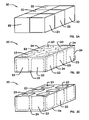
- FIG. 2A is an isometric block diagram of the structure floating foundation of FIG. 1 illustrating the cells.
- FIG. 2B is an isometric view of the structural floating foundation of FIG. 1 illustrating blocks of low density material and an high structural material encapsulating the low density material, according to the invention.
- FIG. 2C is an inverted isometric view of the structural floating foundation of FIG. 2B illustrating exposed surfaces of the low density material, according to the invention.
- FIG. 3A is an isometric view of the cells of the structural floating foundation of FIG. 2A .
- FIG. 3B is an isometric view of the cell of FIG. 3A illustrating a block of low density material or similar material of each cell encapsulated by high structural material, according to the invention.
- FIG. 3C is an inverted isometric view of the cell of FIG. 3B illustrating exposed surfaces of the low density material encapsulated within each cell, according to the invention.
- FIG. 1 is an illustration of a structure 10 comprised of a building 12 resting on a structural floating foundation 20 , according to the invention.
- the structural floating foundation 20 rests upon a building surface 14 .
- a pest control barrier 16 and/or a leveling material 18 such as aggregate or sand may be placed between the structural floating foundation 20 and the building surface 14 .
- the structural floating foundation 20 is illustrated as a combination of cells 22 .
- the composition of the cells of FIG. 2A is more fully illustrated by the isometric view of FIG. 2B which demonstrates a high structure material 24 either partially or fully encapsulating blocks of low density material 23 .
- the high structure material is any material that may be used to encapsulate the blocks of low density material 23 while providing load bearing capacity as needed to support a building 14 .
- this high structure material 24 may include a plethora of materials that may or may not be common in the construction industry and is therefore not limited to concrete or other traditional building materials.
- the high-structure material 24 is concrete.
- Concrete is comprised of cement, aggregate, such as sand or crushed rock, and water.
- the type of cement, the type of aggregate, and the ratio of cement to aggregate to water may be adjusted to affect its density.
- typical concrete, such as concrete using Portland® Cement usually has densities ranging from 90 to 125 pounds per cubic foot.
- Low density material 23 is any material that has a density lower than that of water that also may be effectively encapsulated by the high structural material 24 of this invention.
- the high-structural material 24 would need to be either “water-tight” or “air-tight, depending on the nature of the low-density material 23 .
- the high-structural material 24 would most likely need to fully encapsulate the low density material 23 .
- the structural floating foundation 20 would need to be designed to prevent flood waters from substantially invading the cavities occupied by either gaseous or liquid low density material 23 .
- the low density material 23 is a solid such as polystyrene or similar material.
- polystyrene or similar material has high compression strength. Another advantage of using polystyrene or similar material is that, under normal pressures, it will resist invasion by water, effectively displacing water under normal circumstances. This feature is also advantageous as it eliminates the need to have the high structural material 24 fully encapsulate the low-density material 23 . While any low density material 23 that has a density less than that of water may be used, this exemplary embodiment of the invention comprising a material which possesses a density substantially less than that of water. For the purposes of illustration only, the low density material 23 in this exemplary embodiment of the invention possesses a density approximating one (1) pound per cubic foot. For discussion purposes, the density of water at standard pressures and temperatures approximates 61 lbs per cubic foot.
- the structural floating foundation 20 is created by placing the blocks of low density material 23 on a building surface 14 ( FIG. 1 ) and placing the high structural material 24 over and around the blocks of low density material 23 , thus encapsulating the low density material 23 .
- the ratio of the volume of low density material 23 to the volume of the high structural material 24 is such that the combined density of the resulting structural floating foundation 20 is less than that of water, under normal pressures and temperatures, such as zero to two atmospheres and zero to 200 degrees Celsius.
- the structural floating foundation is intended to float when exposed to flood waters, lifting the building above the indicated flood waters.
- the low density material 23 is a single block.
- this exemplary embodiment of the invention includes a plurality of blocks of low density material 23 .
- the high structure material 24 may be placed in the gaps, thus creating areas of enhanced load bearing capacity and further encapsulating the blocks.
- an optional reinforcing material such as rebar or steel mesh is placed around and, optionally, through the low density material 23 and ultimately enmeshed by the high structure material 24 .
- the properties of such reinforcing material are well known in the art and are not the subject of this invention.
- forms may be placed around the perimeter of the intended foundation to contain the concrete or similar material 24 until it is set. Additionally, the blocks of low density material 23 may be beveled along their lower edges, allowing the high structure material 24 to more fully encapsulate the low density material 23 .
Landscapes
- Engineering & Computer Science (AREA)
- Life Sciences & Earth Sciences (AREA)
- General Life Sciences & Earth Sciences (AREA)
- Mining & Mineral Resources (AREA)
- Paleontology (AREA)
- Civil Engineering (AREA)
- General Engineering & Computer Science (AREA)
- Structural Engineering (AREA)
- Foundations (AREA)
Abstract
An apparatus for providing a foundation for a building structure wherein the foundation comprises a low density material, such as polystyrene, either partially or fully encapsulated by a high structure material, such as concrete. The apparatus is adapted so that the net density of the foundation is less than that of water, allowing the foundation to float when surrounded by water. The density of the foundation may be adapted so that a building placed on the foundation will be lifted above floodwaters by the foundation.
Description
- 1. Field of the Invention
- This invention is related in general to the field of construction. In particular, this invention is a novel method of providing a floating foundation for building structures.
- 2. Description of the Prior Art
- Homes and other buildings typically include some form of a foundation upon which the structure is built. As such, a building's foundation must provide a strong and stable base to attach walls and other structural components to. Traditionally, building foundations have been either placed in the ground or laid on top of the ground.
- Traditional materials used in the construction of foundations are generally very dense, based on the desire that they be structurally strong. As such, traditional foundations consist of concrete or other dense materials, often laid down in one or more pouring. If concrete is used for the foundation, it is traditionally reinforced with steel, such as rebar or steel mesh, to strengthen and stabilize the foundation.
- One problem with traditional foundations is that they are very heavy. Because the foundation is heavy, should a building be exposed to flooding, the foundation traditionally remains emplaced allowing the floodwater to rise above the height of the foundation. When this occurs, the floodwater will first come in contact with the exterior walls and other exterior surfaces of the structure. Once in contact with the exterior walls, etc., flood waters may seep through the wall material or through joints and cracks in the exterior surfaces. When this occurs, damage to the interior and exterior surfaces of the wall may occur as well as damage to the internal components of the wall structures.
- Additionally, once floodwaters seep through the exterior walls, they may damage floor surfaces, furniture, fixtures, and equipment within the structure. In severe cases of flooding, floodwater may also enter the structure through entryways and windows. In any event, floodwater which rises above the height of a building's foundation will most likely result in severe damage to the structure and its contents.
- Accordingly, it is desirable to have a method of constructing a building foundation that will reduce the likelihood of floodwaters rising above said foundation.
- The invention disclosed herein utilizes a structural floating foundation designed to lift a building structure when exposed to flooding. While some or all of the building's foundation may be exposed to floodwaters, the balance of the building's structure should remain above the water's level.
- In one embodiment of the invention, forms are placed around the perimeter of the building's intended foundation. Blocks of
low density material 23 are placed within the area created by the forms. The blocks oflow density material 23, such as polystyrene or other similar material are separated from each other and the forms, creating a gap around each block. Concrete or similar material is then poured over and around the blocks of low density material and within the area defined by the forms, thus creating a hard, durable, and supportive foundation which is much lighter than a traditional foundation. - One characteristic of the polystyrene or similar material is that it need not be sealed from exposure from water. Under normal pressures, such as zero to two atmospheres, water will not normally impregnate the polystyrene or similar material. Because the density of the polystyrene or similar material is very low, the net density of the foundation including the polystyrene and concrete is less than that of water. As such, should the improved foundation be exposed to floodwaters, it will rise, preventing the floodwaters from entering the associated building structure.
- While a building structure's weight is derived primarily from the foundation, the remaining portion of the building will have a non-negligible weight as well. The ratio of high
structural material 24 andlow density material 23 may be adjusted to provide sufficient lift capacity to raise the foundation and the rest of the building structure when surrounded by water. - In one embodiment of the invention, steel or similar material may be introduced within the foundation to strengthen the structural floating foundation including the concrete or similar material.
- In another embodiment of the invention, the blocks of low density material may be beveled along their lower edges to allow the concrete or similar material to flow under a portion of each block, thus more fully encapsulating the low density material.
- In still another embodiment of the invention, the blocks of low density material may be impregnated with pesticides or other chemicals to discourage pests such as termites, other types of insects, and rodents.
- Various other purposes and advantages of the invention will become clear from its description in the specification that follows and from the novel features particularly pointed out in the appended claims. Therefore, to the accomplishment of the objectives described above, this invention comprises the features hereinafter illustrated in the drawings, fully described in the detailed description of the preferred embodiments, and particularly pointed out in the claims. However, such drawings and description disclose just a few of the various ways in which the invention may be practiced and are not limiting.
-
FIG. 1 is an isometric view of a building including a structural floating foundation which is the subject of this invention. -
FIG. 2A is an isometric block diagram of the structure floating foundation ofFIG. 1 illustrating the cells. -
FIG. 2B is an isometric view of the structural floating foundation ofFIG. 1 illustrating blocks of low density material and an high structural material encapsulating the low density material, according to the invention. -
FIG. 2C is an inverted isometric view of the structural floating foundation ofFIG. 2B illustrating exposed surfaces of the low density material, according to the invention. -
FIG. 3A is an isometric view of the cells of the structural floating foundation ofFIG. 2A . -
FIG. 3B is an isometric view of the cell ofFIG. 3A illustrating a block of low density material or similar material of each cell encapsulated by high structural material, according to the invention. -
FIG. 3C is an inverted isometric view of the cell ofFIG. 3B illustrating exposed surfaces of the low density material encapsulated within each cell, according to the invention. - This invention is based on the idea of partially or fully encapsulating low-density material with a material providing a high level of structural support to produce a foundation with a net density less than that of water. Referring to figures, wherein like parts are designated with the same reference numerals and symbols,
FIG. 1 is an illustration of astructure 10 comprised of abuilding 12 resting on a structuralfloating foundation 20, according to the invention. The structuralfloating foundation 20 rests upon abuilding surface 14. Optionally, apest control barrier 16 and/or a levelingmaterial 18 such as aggregate or sand may be placed between the structural floatingfoundation 20 and thebuilding surface 14. - Referring to the isometric block diagram of
FIG. 2A , the structural floatingfoundation 20 is illustrated as a combination ofcells 22. The composition of the cells ofFIG. 2A is more fully illustrated by the isometric view ofFIG. 2B which demonstrates ahigh structure material 24 either partially or fully encapsulating blocks oflow density material 23. As used to describe this invention, the high structure material is any material that may be used to encapsulate the blocks oflow density material 23 while providing load bearing capacity as needed to support abuilding 14. As such, thishigh structure material 24 may include a plethora of materials that may or may not be common in the construction industry and is therefore not limited to concrete or other traditional building materials. However, in this exemplary embodiment of the invention, the high-structure material 24 is concrete. - Concrete is comprised of cement, aggregate, such as sand or crushed rock, and water. The type of cement, the type of aggregate, and the ratio of cement to aggregate to water may be adjusted to affect its density. However, typical concrete, such as concrete using Portland® Cement, usually has densities ranging from 90 to 125 pounds per cubic foot.
-
Low density material 23, as used to describe this invention, is any material that has a density lower than that of water that also may be effectively encapsulated by the highstructural material 24 of this invention. However, if thelow density material 23 is gaseous or liquid in nature, the high-structural material 24 would need to be either “water-tight” or “air-tight, depending on the nature of the low-density material 23. Additionally, the high-structural material 24 would most likely need to fully encapsulate thelow density material 23. Barring complete encapsulation by the highstructural material 24, the structural floatingfoundation 20 would need to be designed to prevent flood waters from substantially invading the cavities occupied by either gaseous or liquidlow density material 23. However, in this exemplary embodiment of the invention, thelow density material 23 is a solid such as polystyrene or similar material. - One of the advantages of using polystyrene or similar material is its high compression strength. Another advantage of using polystyrene or similar material is that, under normal pressures, it will resist invasion by water, effectively displacing water under normal circumstances. This feature is also advantageous as it eliminates the need to have the high
structural material 24 fully encapsulate the low-density material 23. While anylow density material 23 that has a density less than that of water may be used, this exemplary embodiment of the invention comprising a material which possesses a density substantially less than that of water. For the purposes of illustration only, thelow density material 23 in this exemplary embodiment of the invention possesses a density approximating one (1) pound per cubic foot. For discussion purposes, the density of water at standard pressures and temperatures approximates 61 lbs per cubic foot. - The structural floating
foundation 20 is created by placing the blocks oflow density material 23 on a building surface 14 (FIG. 1 ) and placing the highstructural material 24 over and around the blocks oflow density material 23, thus encapsulating thelow density material 23. In this embodiment of the invention, the ratio of the volume oflow density material 23 to the volume of the highstructural material 24 is such that the combined density of the resulting structural floatingfoundation 20 is less than that of water, under normal pressures and temperatures, such as zero to two atmospheres and zero to 200 degrees Celsius. As such, the structural floating foundation is intended to float when exposed to flood waters, lifting the building above the indicated flood waters. - In one embodiment of the invention, the
low density material 23 is a single block. However, this exemplary embodiment of the invention includes a plurality of blocks oflow density material 23. By separating the blocks oflow density material 23 with gaps between each other and an optional form surrounding the intended foundation, thehigh structure material 24 may be placed in the gaps, thus creating areas of enhanced load bearing capacity and further encapsulating the blocks. - In this exemplary embodiment of the invention, an optional reinforcing material such as rebar or steel mesh is placed around and, optionally, through the
low density material 23 and ultimately enmeshed by thehigh structure material 24. The properties of such reinforcing material are well known in the art and are not the subject of this invention. - If concrete or similar material is used as the
high structure material 24, then forms may be placed around the perimeter of the intended foundation to contain the concrete orsimilar material 24 until it is set. Additionally, the blocks oflow density material 23 may be beveled along their lower edges, allowing thehigh structure material 24 to more fully encapsulate thelow density material 23. - Those skilled in the art of making building foundations may develop other embodiments of the present invention. However, the terms and expressions which have been employed in the foregoing specification are used therein as terms of description and not of limitation, and there is no intention in the use of such terms and expressions of excluding equivalents of the features shown and described or portions thereof, it being recognized that the scope of the invention is defined and limited only by the claims which follow.
Claims (10)
1. a structural floating foundation, comprising:
low density material; and
high structure material adapted to at least partially encapsulate said low density material;
wherein said high structure material is further adapted to provide a load bearing surface for a building structure;
and further wherein the net density of the structural floating foundation is less than the density of water.
2. The structural floating foundation of claim 1 , wherein the low density material comprises polystyrene.
3. The structural floating foundation of claim 1 , wherein the high structure material comprises concrete.
4. The structural floating foundation of claim 1 , wherein the high structure material comprises reinforcing material.
5. The structural floating foundation of claim 4 , wherein the reinforcing material comprises steel.
6. The structural floating foundation of claim 5 , wherein the reinforcing material comprises steel mesh.
7. The structural floating foundation of claim 1 , wherein the high structure material is adapted to completely encapsulate the low density material.
8. The structural floating foundation of claim 1 , wherein the low density material is a solid at zero to two atmospheres and zero to 200 degrees Celsius.
9. The structural floating foundation of claim 8 , wherein the low density material comprises a lower edge and said lower edge is beveled.
10. The structural floating foundation of claim 9 , wherein the high structure material is placed under the lower edge and is adapted to more fully encapsulate the low density material.
Priority Applications (1)
| Application Number | Priority Date | Filing Date | Title |
|---|---|---|---|
| US11/588,516 US20080098678A1 (en) | 2006-10-27 | 2006-10-27 | Structural floating foundation |
Applications Claiming Priority (1)
| Application Number | Priority Date | Filing Date | Title |
|---|---|---|---|
| US11/588,516 US20080098678A1 (en) | 2006-10-27 | 2006-10-27 | Structural floating foundation |
Publications (1)
| Publication Number | Publication Date |
|---|---|
| US20080098678A1 true US20080098678A1 (en) | 2008-05-01 |
Family
ID=39328477
Family Applications (1)
| Application Number | Title | Priority Date | Filing Date |
|---|---|---|---|
| US11/588,516 Abandoned US20080098678A1 (en) | 2006-10-27 | 2006-10-27 | Structural floating foundation |
Country Status (1)
| Country | Link |
|---|---|
| US (1) | US20080098678A1 (en) |
Cited By (3)
| Publication number | Priority date | Publication date | Assignee | Title |
|---|---|---|---|---|
| US20120279490A1 (en) * | 2009-12-29 | 2012-11-08 | Create Technologies, Inc. | Wave generated energy focusing lens and reflector for solar concentration, collection, and harnessing |
| US8443573B1 (en) * | 2010-10-26 | 2013-05-21 | Kontek Industries, Inc. | Blast-resistant foundations |
| JP2015518931A (en) * | 2012-06-05 | 2015-07-06 | ブレー,チャールズ,コールダー | Modular foundation that can withstand ground movement |
Citations (7)
| Publication number | Priority date | Publication date | Assignee | Title |
|---|---|---|---|---|
| US3799093A (en) * | 1973-05-07 | 1974-03-26 | W Thomson | Floating prestressed concrete wharf |
| US4318361A (en) * | 1979-08-06 | 1982-03-09 | Builders Concrete, Inc. | Lightweight concrete marine float and method of constructing same |
| US4693631A (en) * | 1984-08-30 | 1987-09-15 | Pacific Marina Developments Pty. Ltd. | Floating breakwater |
| US5775248A (en) * | 1996-12-18 | 1998-07-07 | Simola; Charles H. | Stabilized float drum |
| US6199502B1 (en) * | 1999-08-27 | 2001-03-13 | Jerry L. Mattson | Concrete module for floating structures and method of construction |
| US20040040488A1 (en) * | 2002-08-30 | 2004-03-04 | Paul Trepanier | Pontoon and method of making the same |
| US6971327B2 (en) * | 2003-03-17 | 2005-12-06 | Mattson Jerry L | Concrete module for floating structures and method of construction |
-
2006
- 2006-10-27 US US11/588,516 patent/US20080098678A1/en not_active Abandoned
Patent Citations (7)
| Publication number | Priority date | Publication date | Assignee | Title |
|---|---|---|---|---|
| US3799093A (en) * | 1973-05-07 | 1974-03-26 | W Thomson | Floating prestressed concrete wharf |
| US4318361A (en) * | 1979-08-06 | 1982-03-09 | Builders Concrete, Inc. | Lightweight concrete marine float and method of constructing same |
| US4693631A (en) * | 1984-08-30 | 1987-09-15 | Pacific Marina Developments Pty. Ltd. | Floating breakwater |
| US5775248A (en) * | 1996-12-18 | 1998-07-07 | Simola; Charles H. | Stabilized float drum |
| US6199502B1 (en) * | 1999-08-27 | 2001-03-13 | Jerry L. Mattson | Concrete module for floating structures and method of construction |
| US20040040488A1 (en) * | 2002-08-30 | 2004-03-04 | Paul Trepanier | Pontoon and method of making the same |
| US6971327B2 (en) * | 2003-03-17 | 2005-12-06 | Mattson Jerry L | Concrete module for floating structures and method of construction |
Cited By (6)
| Publication number | Priority date | Publication date | Assignee | Title |
|---|---|---|---|---|
| US20120279490A1 (en) * | 2009-12-29 | 2012-11-08 | Create Technologies, Inc. | Wave generated energy focusing lens and reflector for solar concentration, collection, and harnessing |
| US9360235B2 (en) * | 2009-12-29 | 2016-06-07 | OAS Design Group, Inc. | Wave generated energy focusing lens and reflector for solar concentration, collection, and harnessing |
| US10359214B2 (en) | 2009-12-29 | 2019-07-23 | OAS Design Group, Inc. | Wave generated energy focusing lens and reflector for solar concentration, collection, and harnessing |
| US8443573B1 (en) * | 2010-10-26 | 2013-05-21 | Kontek Industries, Inc. | Blast-resistant foundations |
| US8468760B1 (en) * | 2010-10-26 | 2013-06-25 | Kontek Industries, Inc | Blast-resistant foundations |
| JP2015518931A (en) * | 2012-06-05 | 2015-07-06 | ブレー,チャールズ,コールダー | Modular foundation that can withstand ground movement |
Similar Documents
| Publication | Publication Date | Title |
|---|---|---|
| US20100154348A1 (en) | Construction for buildings protected against radiation | |
| CA2210789A1 (en) | Flotation system for buildings | |
| US4799348A (en) | Method and equipment for making a rigid slab enabling to carry a building | |
| US4365451A (en) | Poured adobe building construction and method of forming same | |
| US20080098678A1 (en) | Structural floating foundation | |
| US9970193B1 (en) | System and method for the construction of dwellings | |
| JP3897107B2 (en) | Structure and its construction method by bubble lightweight mixed earth method | |
| US20170037591A1 (en) | Aboveground foundation for building superstructures | |
| KR101117354B1 (en) | Lightweight material mounding structure and method for constructing the same | |
| CN217710837U (en) | Anti-floating underground building | |
| JP4176235B2 (en) | Liquefaction prevention method | |
| US9038328B2 (en) | Aboveground safety shelter | |
| RU55388U1 (en) | SPATIAL REINFORCED CONCRETE FOUNDATION PLATFORM FOR SMALL-STOREY BUILDINGS FOR CONSTRUCTION IN SPECIAL GROUND CONDITIONS AND SEISMICITY IN ASSEMBLY AND MONOLITHIC OPTIONS | |
| JP3154156B2 (en) | How to prevent floating of underground structures | |
| WO2019199317A1 (en) | System and method for the construction of dwellings | |
| CN114382107B (en) | Anti-floating underground buildings | |
| KR102229534B1 (en) | Wave dissipating block using of used tires and a inclined wall structure thereof | |
| US4594825A (en) | Cantilevered support member and foundation unit | |
| JP3727320B2 (en) | Ground reinforcement, foundation structure and foundation structure construction method | |
| GB2505765A (en) | A suspended concrete platform with platform formworks | |
| JPH0536044Y2 (en) | ||
| JPH06287965A (en) | Foundation for soft ground and construction method for foundation in soft ground | |
| JP2002030680A (en) | Cellar structure | |
| JP2002021094A (en) | Foundation structure for wooden house | |
| JPH06185088A (en) | Underground foundation structure and its construction method |
Legal Events
| Date | Code | Title | Description |
|---|---|---|---|
| STCB | Information on status: application discontinuation |
Free format text: ABANDONED -- FAILURE TO RESPOND TO AN OFFICE ACTION |