US20080098676A1 - Connectors and Methods of Construction for a Precast Special Concrete Moment Resisting Shear Wall and Precast Special Concrete Moment Resisting Frame Building Panel System - Google Patents
Connectors and Methods of Construction for a Precast Special Concrete Moment Resisting Shear Wall and Precast Special Concrete Moment Resisting Frame Building Panel System Download PDFInfo
- Publication number
- US20080098676A1 US20080098676A1 US11/554,611 US55461106A US2008098676A1 US 20080098676 A1 US20080098676 A1 US 20080098676A1 US 55461106 A US55461106 A US 55461106A US 2008098676 A1 US2008098676 A1 US 2008098676A1
- Authority
- US
- United States
- Prior art keywords
- wall
- panel
- connector
- concrete
- building
- Prior art date
- Legal status (The legal status is an assumption and is not a legal conclusion. Google has not performed a legal analysis and makes no representation as to the accuracy of the status listed.)
- Abandoned
Links
- 239000004567 concrete Substances 0.000 title claims abstract description 52
- 238000000034 method Methods 0.000 title claims abstract description 17
- 238000010276 construction Methods 0.000 title description 18
- 239000011178 precast concrete Substances 0.000 claims abstract description 19
- 230000000712 assembly Effects 0.000 claims abstract description 4
- 238000000429 assembly Methods 0.000 claims abstract description 4
- 238000009428 plumbing Methods 0.000 claims abstract description 3
- 230000002787 reinforcement Effects 0.000 claims description 30
- 239000000463 material Substances 0.000 claims description 18
- 229910000831 Steel Inorganic materials 0.000 claims description 12
- 239000010959 steel Substances 0.000 claims description 12
- 238000005266 casting Methods 0.000 claims description 11
- 238000013016 damping Methods 0.000 claims description 8
- 238000009413 insulation Methods 0.000 claims description 6
- 229910001335 Galvanized steel Inorganic materials 0.000 claims description 5
- 238000004873 anchoring Methods 0.000 claims description 5
- 239000006260 foam Substances 0.000 claims description 5
- 239000008397 galvanized steel Substances 0.000 claims description 5
- 229910001369 Brass Inorganic materials 0.000 claims description 2
- 239000010951 brass Substances 0.000 claims description 2
- 238000004519 manufacturing process Methods 0.000 claims description 2
- 239000011800 void material Substances 0.000 claims 4
- 239000000835 fiber Substances 0.000 claims 3
- 239000011440 grout Substances 0.000 claims 2
- 238000003780 insertion Methods 0.000 claims 2
- 230000037431 insertion Effects 0.000 claims 2
- 238000005452 bending Methods 0.000 claims 1
- 238000013461 design Methods 0.000 abstract description 17
- 229910000746 Structural steel Inorganic materials 0.000 abstract description 12
- 239000002131 composite material Substances 0.000 abstract description 4
- 239000011513 prestressed concrete Substances 0.000 abstract description 4
- 239000002023 wood Substances 0.000 abstract description 4
- 230000000694 effects Effects 0.000 abstract description 3
- 238000000465 moulding Methods 0.000 abstract description 3
- 239000011150 reinforced concrete Substances 0.000 abstract description 3
- 238000009433 steel framing Methods 0.000 abstract description 2
- 239000010410 layer Substances 0.000 description 10
- 238000005516 engineering process Methods 0.000 description 7
- 239000004568 cement Substances 0.000 description 5
- 239000011210 fiber-reinforced concrete Substances 0.000 description 5
- -1 admixtures Substances 0.000 description 4
- 210000003195 fascia Anatomy 0.000 description 4
- 239000011381 foam concrete Substances 0.000 description 4
- 239000000203 mixture Substances 0.000 description 4
- 229920006327 polystyrene foam Polymers 0.000 description 4
- 238000012360 testing method Methods 0.000 description 4
- 229910045601 alloy Inorganic materials 0.000 description 3
- 239000000956 alloy Substances 0.000 description 3
- 239000003795 chemical substances by application Substances 0.000 description 3
- 238000007689 inspection Methods 0.000 description 3
- 238000002360 preparation method Methods 0.000 description 3
- 238000011160 research Methods 0.000 description 3
- 230000003068 static effect Effects 0.000 description 3
- 239000002344 surface layer Substances 0.000 description 3
- 238000004458 analytical method Methods 0.000 description 2
- 230000008901 benefit Effects 0.000 description 2
- 238000009435 building construction Methods 0.000 description 2
- 238000004364 calculation method Methods 0.000 description 2
- 239000011248 coating agent Substances 0.000 description 2
- 238000000576 coating method Methods 0.000 description 2
- 239000003086 colorant Substances 0.000 description 2
- 238000007596 consolidation process Methods 0.000 description 2
- 238000011156 evaluation Methods 0.000 description 2
- 238000009472 formulation Methods 0.000 description 2
- 238000009432 framing Methods 0.000 description 2
- 230000005484 gravity Effects 0.000 description 2
- 230000007246 mechanism Effects 0.000 description 2
- 238000012986 modification Methods 0.000 description 2
- 230000004048 modification Effects 0.000 description 2
- 239000004033 plastic Substances 0.000 description 2
- 229920003023 plastic Polymers 0.000 description 2
- 238000009436 residential construction Methods 0.000 description 2
- XLYOFNOQVPJJNP-UHFFFAOYSA-N water Substances O XLYOFNOQVPJJNP-UHFFFAOYSA-N 0.000 description 2
- OKTJSMMVPCPJKN-UHFFFAOYSA-N Carbon Chemical compound [C] OKTJSMMVPCPJKN-UHFFFAOYSA-N 0.000 description 1
- 241000295126 Cascadia Species 0.000 description 1
- 229910001294 Reinforcing steel Inorganic materials 0.000 description 1
- 230000006978 adaptation Effects 0.000 description 1
- 238000007792 addition Methods 0.000 description 1
- 230000004075 alteration Effects 0.000 description 1
- 230000009286 beneficial effect Effects 0.000 description 1
- 229910052799 carbon Inorganic materials 0.000 description 1
- 239000003638 chemical reducing agent Substances 0.000 description 1
- 238000004040 coloring Methods 0.000 description 1
- 238000007796 conventional method Methods 0.000 description 1
- 238000005034 decoration Methods 0.000 description 1
- 238000011161 development Methods 0.000 description 1
- 238000006073 displacement reaction Methods 0.000 description 1
- 238000009826 distribution Methods 0.000 description 1
- 230000007613 environmental effect Effects 0.000 description 1
- 239000011152 fibreglass Substances 0.000 description 1
- 238000011049 filling Methods 0.000 description 1
- 238000009408 flooring Methods 0.000 description 1
- 239000010881 fly ash Substances 0.000 description 1
- 238000009415 formwork Methods 0.000 description 1
- 230000006870 function Effects 0.000 description 1
- 239000010440 gypsum Substances 0.000 description 1
- 229910052602 gypsum Inorganic materials 0.000 description 1
- 238000009434 installation Methods 0.000 description 1
- 238000003475 lamination Methods 0.000 description 1
- 239000004816 latex Substances 0.000 description 1
- 229920000126 latex Polymers 0.000 description 1
- 238000012423 maintenance Methods 0.000 description 1
- 231100000647 material safety data sheet Toxicity 0.000 description 1
- 238000002156 mixing Methods 0.000 description 1
- 229940028444 muse Drugs 0.000 description 1
- 230000008520 organization Effects 0.000 description 1
- 238000010422 painting Methods 0.000 description 1
- 239000011120 plywood Substances 0.000 description 1
- GMVPRGQOIOIIMI-DWKJAMRDSA-N prostaglandin E1 Chemical compound CCCCC[C@H](O)\C=C\[C@H]1[C@H](O)CC(=O)[C@@H]1CCCCCCC(O)=O GMVPRGQOIOIIMI-DWKJAMRDSA-N 0.000 description 1
- 230000009467 reduction Effects 0.000 description 1
- 230000001105 regulatory effect Effects 0.000 description 1
- 230000003014 reinforcing effect Effects 0.000 description 1
- 239000011347 resin Substances 0.000 description 1
- 229920005989 resin Polymers 0.000 description 1
- 239000000565 sealant Substances 0.000 description 1
- 229910021487 silica fume Inorganic materials 0.000 description 1
- 238000004088 simulation Methods 0.000 description 1
- 239000002893 slag Substances 0.000 description 1
- 239000002689 soil Substances 0.000 description 1
- 239000007787 solid Substances 0.000 description 1
- 239000010935 stainless steel Substances 0.000 description 1
- 229910001220 stainless steel Inorganic materials 0.000 description 1
- 239000012209 synthetic fiber Substances 0.000 description 1
- 229920002994 synthetic fiber Polymers 0.000 description 1
- 238000012956 testing procedure Methods 0.000 description 1
- 238000009431 timber framing Methods 0.000 description 1
- 238000013519 translation Methods 0.000 description 1
- 150000003673 urethanes Chemical class 0.000 description 1
- 229910052720 vanadium Inorganic materials 0.000 description 1
- 125000000391 vinyl group Chemical group [H]C([*])=C([H])[H] 0.000 description 1
- 229920002554 vinyl polymer Polymers 0.000 description 1
- 238000004078 waterproofing Methods 0.000 description 1
- 229910052882 wollastonite Inorganic materials 0.000 description 1
- 239000010456 wollastonite Substances 0.000 description 1
Images


Classifications
-
- E—FIXED CONSTRUCTIONS
- E04—BUILDING
- E04B—GENERAL BUILDING CONSTRUCTIONS; WALLS, e.g. PARTITIONS; ROOFS; FLOORS; CEILINGS; INSULATION OR OTHER PROTECTION OF BUILDINGS
- E04B1/00—Constructions in general; Structures which are not restricted either to walls, e.g. partitions, or floors or ceilings or roofs
- E04B1/02—Structures consisting primarily of load-supporting, block-shaped, or slab-shaped elements
- E04B1/04—Structures consisting primarily of load-supporting, block-shaped, or slab-shaped elements the elements consisting of concrete, e.g. reinforced concrete, or other stone-like material
- E04B1/043—Connections specially adapted therefor
-
- B—PERFORMING OPERATIONS; TRANSPORTING
- B28—WORKING CEMENT, CLAY, OR STONE
- B28B—SHAPING CLAY OR OTHER CERAMIC COMPOSITIONS; SHAPING SLAG; SHAPING MIXTURES CONTAINING CEMENTITIOUS MATERIAL, e.g. PLASTER
- B28B19/00—Machines or methods for applying the material to surfaces to form a permanent layer thereon
- B28B19/003—Machines or methods for applying the material to surfaces to form a permanent layer thereon to insulating material
-
- B—PERFORMING OPERATIONS; TRANSPORTING
- B28—WORKING CEMENT, CLAY, OR STONE
- B28B—SHAPING CLAY OR OTHER CERAMIC COMPOSITIONS; SHAPING SLAG; SHAPING MIXTURES CONTAINING CEMENTITIOUS MATERIAL, e.g. PLASTER
- B28B23/00—Arrangements specially adapted for the production of shaped articles with elements wholly or partly embedded in the moulding material; Production of reinforced objects
- B28B23/0025—Arrangements specially adapted for the production of shaped articles with elements wholly or partly embedded in the moulding material; Production of reinforced objects with installation or service material, e.g. tubes for electricity or water
-
- B—PERFORMING OPERATIONS; TRANSPORTING
- B28—WORKING CEMENT, CLAY, OR STONE
- B28B—SHAPING CLAY OR OTHER CERAMIC COMPOSITIONS; SHAPING SLAG; SHAPING MIXTURES CONTAINING CEMENTITIOUS MATERIAL, e.g. PLASTER
- B28B7/00—Moulds; Cores; Mandrels
- B28B7/0002—Auxiliary parts or elements of the mould
- B28B7/0014—Fastening means for mould parts, e.g. for attaching mould walls on mould tables; Mould clamps
- B28B7/0026—Fastening means for mould parts, e.g. for attaching mould walls on mould tables; Mould clamps using adhesive
-
- B—PERFORMING OPERATIONS; TRANSPORTING
- B28—WORKING CEMENT, CLAY, OR STONE
- B28B—SHAPING CLAY OR OTHER CERAMIC COMPOSITIONS; SHAPING SLAG; SHAPING MIXTURES CONTAINING CEMENTITIOUS MATERIAL, e.g. PLASTER
- B28B7/00—Moulds; Cores; Mandrels
- B28B7/0029—Moulds or moulding surfaces not covered by B28B7/0058 - B28B7/36 and B28B7/40 - B28B7/465, e.g. moulds assembled from several parts
- B28B7/0032—Moulding tables or similar mainly horizontal moulding surfaces
-
- E—FIXED CONSTRUCTIONS
- E04—BUILDING
- E04B—GENERAL BUILDING CONSTRUCTIONS; WALLS, e.g. PARTITIONS; ROOFS; FLOORS; CEILINGS; INSULATION OR OTHER PROTECTION OF BUILDINGS
- E04B1/00—Constructions in general; Structures which are not restricted either to walls, e.g. partitions, or floors or ceilings or roofs
- E04B1/02—Structures consisting primarily of load-supporting, block-shaped, or slab-shaped elements
- E04B1/04—Structures consisting primarily of load-supporting, block-shaped, or slab-shaped elements the elements consisting of concrete, e.g. reinforced concrete, or other stone-like material
- E04B1/06—Structures consisting primarily of load-supporting, block-shaped, or slab-shaped elements the elements consisting of concrete, e.g. reinforced concrete, or other stone-like material the elements being prestressed
-
- E—FIXED CONSTRUCTIONS
- E04—BUILDING
- E04B—GENERAL BUILDING CONSTRUCTIONS; WALLS, e.g. PARTITIONS; ROOFS; FLOORS; CEILINGS; INSULATION OR OTHER PROTECTION OF BUILDINGS
- E04B2/00—Walls, e.g. partitions, for buildings; Wall construction with regard to insulation; Connections specially adapted to walls
- E04B2/84—Walls made by casting, pouring, or tamping in situ
- E04B2/86—Walls made by casting, pouring, or tamping in situ made in permanent forms
- E04B2002/8682—Mixed technique using permanent and reusable forms
Definitions
- This invention deals with building construction and more specifically with the construction of prefabricated special concrete shear-walls, prefabricated special concrete moment frames, hybrid pre-cast/site cast concrete construction, ductile reinforcement connections, and new and novel methods of fulfilling the requirements of the seismic specifications of the current and proposed model building codes.
- a typical 7-1 ⁇ 2′′ wall section requires approximately 55% of the concrete required for an equivalent solid concrete wall, yet provides in excess of 85% of the equivalent effective load capacity, or about 8,000 lbs./lf.
- the IBC 2006 and ACI 318-05 further reference the “American Society of Civil Engineers Minimum Design Loads for Buildings and Other Structures”, or “ASCE 7”, Most of the specifications and details are for cast in place concrete, and any reference to pre-cast concrete generally or in regards to seismic requirements particularly are that any design with pre-cast concrete components should meet or exceed the strength requirements for cast in place concrete.
- PCI Precast Concrete Institute
- PCI-99 PCI Precast and Prestressed Concrete Handbook
- HUD Department of Housing and Urban Development
- FEMA Federal Emergency Management Agency
- BSSC Building Seismic Safety Council
- NHRP National Earthquake Hazard Reduction Program
- ERI Earthquake Engineering Research Institute
- ATC Earthquake Technology Council
- SESAC Scientific Earthquake Studies Advisory Committee
- NIST National Institute of Standards and Technologies
- NIST National Science Foundation
- NSF United States Geological Survey
- USGS United States Geological Survey
- ERDC Army Engineer Research and Development Center
- CUREE the Consortium of Universities for Research in Earthquake Engineering
- MCEER Multidisciplinary Center for Earthquake Engineering
- PEER Pacific Earthquake Engineering Resource Center
- NEC National Hazards Center at the University of Colorado
- SCEC Southern California Earthquake Center
- MAEC Mid-America Earthquake Center
- NEES Network for Earthquake Engineering Simulation
- Earthquake preparedness organizations include the Cascadia Region Earthquake Workgroup, (CREW), the Western States Seismic Policy Council, (WSSPC), the Northeast States Emergency Consortium, (NSEC), and the Central US Earthquake Consortium, (CUSEC).
- CREW Cascadia Region Earthquake Workgroup
- WSSPC Western States Seismic Policy Council
- NSEC Northeast States Emergency Consortium
- CUSEC Central US Earthquake Consortium
- HUD has long recognized the potential benefits of panelized building construction and in September of 2004 it presented a document entitled “Residential Panels Benchmark Requirements”, which outlined the state of the art at that time, categorized the various types of panel construction, and established some criteria for evaluating the various methods.
- HUD prepared a list of performance measures that was refined to “10 headings to focus the measures and to allow them to dovetail with code requirements, which would permit the performance measures to relate directly to relevant code citations.”
- the “Superior Wall SystemTM”, is not, however, available in areas with significant potential for seismic activity, (seismic zones D, E, and F.)
- the wall panel system herein described offers a building system conforming to the existing model codes for use anywhere including regions of high seismic activity.
- the wall panel system offers an economical building system that is beneficial to environmental conservation, durable, non-flammable, thermally efficient, attractive, and flexible to adaptations of conventional building technologies, components, and accessories.
- the diagonal wall connectors and wall anchor/shear plate with post-tensioning brace plate connectors of the present invention along with the building methods described, provide a wall panel connection that is as strong or stronger than the wall panels themselves, as well as being ductile and therefore able to dissipate substantial energy as that energy is transmitted amongst the various portions of the building component system during a seismic event.
- the dimensions of the columns are not limited by the dimensions of the wall panels, and therefore a multiple story construction may be designed according to the engineering requirements of a precast concrete moment frame building.
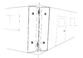
- FIG. 1 is a perspective view of two joined wall panels of the preferred embodiment of the invention attached as an outside corner of a building.
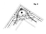
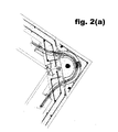
- FIG. 2 is a partial cross section view of the outside corner connection of two wall panels and an outside corner panel with the structural steel connector boundary element exposed and diagramming the typical reinforcement and tensioning strand of the preferred embodiment of the invention.
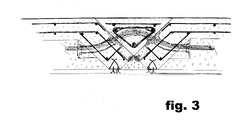
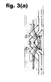
- FIG. 3 is a partial cross section view of the planar wall connection of two wall panels and a center column panel with the structural steel connector boundary element exposed and diagramming the typical reinforcement and tensioning strand of the preferred embodiment of the invention.
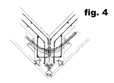
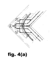
- FIG. 4 is a partial cross section view of the inside corner connection of two wall panels with the structural steel connector boundary element exposed and diagramming the typical reinforcement and tensioning strand of the preferred embodiment of the invention.
- FIG. 5 is a plan and elevation view of the connector of claim 1 .
- FIG. 6 is a plan and elevation view of the connector of claim 6 .
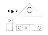
- FIG. 7 is a plan and elevation view of the connector of claim 12 .
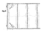
- FIG. 8 is an elevation view of the a wall anchor/shear plate with post-tensioning brace plate of claim 12 installed within the bottom and the top of the first wall cavity adjoining a panel end.
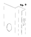
- FIG. 9 is a perspective view of the connector of claim 1 .
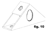
- FIG. 10 is a perspective view of the wall anchor/shear plate with post-tensioning brace plate of claim 12 .
- FIG. 2( a ) is an enlargement of FIG. 2 .
- FIG. 3( a ) is an enlargement of FIG. 3 .
- FIG. 4( a ) is an enlargement of FIG. 4 .
- a feasibility study is performed and upon acceptance an estimate of the building and construction costs is prepared.
- the licensed panel manufacturer prepares the necessary plans and documentation for permit application, including engineering of the structural assembly components, structural walls, columns, beams, diaphragms, moment frames, trusses, reinforcement bar, wire, cable, anchors, inserts, plates, ductile connectors, channel, tubing, and any other embedded elements and any other structural members.
- Structural steel must conform to one of the following specifications:
- Reusable assembly molds are formed on a horizontal surface or on a surface prepared with architectural features or designs, according to the drawings.
- the fascia of the mold may be crafted in a variety of ways to suit the particular application, or prepared directly upon a suitably flat surface with a proper seal and release agent.
- Some of the more common mold forming materials are lumber, plywood, polystyrene foam, stainless steel, or fiberglass and resins. Sometimes reinforced latex is used to make castings of existing complex shapes. Other applications may use gypsum and/or cement and urethanes or vinyl.
- the panel is framed at its top and bottom to establish the precise height of the panel. Additional components to provide for openings in the panel for the attachment of frames for doors, windows, or other features are placed against the mold face, with bracing and clamping devices to secure the components precisely in the mold.
- Corner column and center column panel molds are formed with fascia corresponding to the adjoining wall panels as described in the drawings.
- the ends of wall panel molds have a diagonal face that is facilitated by a diagonal wedge to provide a bracing surface to the ductile panel end connector.
- the wedge is placed perpendicular between the top and bottom of the mold, aligned and set to the precise dimensions of the panel.
- the mold is suitably prepared with sealants and release agents to facilitate the production of the panel.
- a surface layer of fiber-reinforced engineered cement composite (ECC) or other approved exterior type cement coating material, (stucco) or other cementitious materials as specified by the architectural or engineering documentation containing the specified coloring and waterproofing agents is applied to the entire exterior surface of the panel, (the inner face of the mold) sufficient to reach a uniform level surface and then such additional depth as may be required for the engineering of the particular application, (typically a minimum of 1′′.)
- Corner column panel molds are applied with a surface layer to each orthogonal face either simultaneously with the corner of the mold downwards, (each face of a typical corner at 45 degrees from horizontal), or in the case of molds which are particularly smooth or where the cement coating is not viscous enough to adhere to the mold face then each face is applied alternately in the horizontal position and allowed to set before alternating with the adjoining face.
- Center column panel molds with diagonal wedges to form the sides (edges) of the column are applied with a surface layer to the face.
- ductile panel end connector which is a boundary element plate that is fabricated of certified mill test steel plate and with slots in the end face are attached to the reinforcement assembly of Prestressing strand, welded wire and/or reinforcing bar.
- a single continuous connector plate extends from the top to the bottom of the panels, however, in many cases it may be more economical to install two or more shorter connectors.
- Any components such as threaded inserts, anchors, plates, sleeves, ductile connectors, pre-stressing connections and post-tensioning ducts and such other devices as may be necessary to fulfill the requirements of the code and as specified by the engineering documentation are placed into the mold with suitable means for precision placement of all components in relation to the dimensions of the panel and according to the drawings. Prestressing of the reinforcement is performed to the engineering specifications.
- a second layer of fiber reinforced concrete, ECC, foamed concrete, or other cementitious material as specified in the engineering documentation is applied over the first layer and covering the reinforcement assembly to the prescribed thickness of the building shell, (typically a minimum of 1-1 ⁇ 4′′) or as specified in the engineering documentation. Threaded inserts for the attachment of hooks for lifting and moving the panels may be placed along the top of the panels if they are not already incorporated in the reinforcement assembly.
- Foam or other forming materials to shape the interior ribs and beams of the wall panel are inserted into the panel assembly and glued, clamped, and braced to secure its position within the mold.
- a third layer of fiber reinforced concrete, ECC, foamed concrete, or other cementitous material as specified in the engineering documentation is applied over the second layer and covering the reinforcement assembly to the prescribed thickness of the wall panel, (typically a minimum of 3 ⁇ 4′′, for a typical minimum shell thickness of 2-3 ⁇ 4′′.)
- the interior of the wall is typically molded by forming with polystyrene foam that remains attached to the wall panel.
- the forming creates “ribs” and “beams” that are designed to emulate conventional framing, (studs, plates, etc.) so that conventional wall board, moldings, etc. and fasteners can be attached in the customary way.
- An assembly of polystyrene foam blocks is placed into the mold and fastened or braced with suitable anchoring to maintain its position during the final casting procedure.
- the rib configuration reduces the weight of the wall, provides substantial strength while minimizing the surface area exposed to the interior for better thermal efficiency, provides an area for thermal insulation in the finished wall, and facilitates the wall panel conforming to the specified wall dimensions.
- Devices such as electrical boxes, cable clips, etc. which are ordinarily nailed in wood frame construction may have their nails replaced with appropriate screw type anchors and may be inserted into cut-outs of the polystyrene foam adjoining the ribbed portion of the form according to the plans
- a trowel is drawn between the forms or between the perimeters of door or window framed openings and the forms and any excess cementitious material is removed.
- a modified 1-5 ⁇ 8′′ 25 gauge galvanized steel “hat channel” which has been riveted, welded, glued, or otherwise closed to form a triangular cross section is embedded into the concrete along the top, bottom, and along any other horizontal elements of the panel, (to replicate top and bottom plates, sub sills, headers, etc.), and along each rib or vertical element, (to replicate studs, trimmers, etc.), to facilitate the eventual attachment of the wall board and/or other interior wall materials.
- an unmodified 1-5 ⁇ 8′′ 25 gauge galvanized steel “hat channel” which has been fitted with an insulation strip on its interior face is embedded into the concrete along the top, bottom, and along any other horizontal elements of the panel, (to replicate top and bottom plates, sub sills, headers, etc.), and along each rib or vertical element, (to replicate studs, trimmers, etc.), to facilitate the eventual attachment of the wall board or other interior wall materials.
- This embodiment requires larger ribs and beam portions for embedment, and typically is somewhat more labor intensive.
- outside corner column molds are positioned with the corner down.
- Reinforcement according to the drawings (including metallic or plastic ducts for the passage of post-tensioning cable), are placed within the mold and foam or other forming material is situated to create a cavity.
- the form is filled with a layer of fiber reinforced concrete, ECC, foamed concrete, or other cementitious material as specified in the engineering documentation is applied over the first layer of ECC and covering the reinforcement assembly to the prescribed thickness of the building shell, (typically a minimum of 1-1 ⁇ 4′′). Threaded inserts for the attachment of hooks for lifting and moving the panels may be placed along the top of the panels if they are not already incorporated in the reinforcement assembly.
- the sides of the column fascia are now diagonal, to meet flush with the diagonal ends of the connected building panels to form the finished building corner assembly.
- Center column molds are positioned with the panel face down. Reinforcement according to the drawings is placed upon the first layer of ECC within the mold. Diagonal ends partially enclose the mold cavity and it is therefore particularly important with this element to assure the proper consolidation of the ECC with vibration.
- the form is filled with a second layer of ECC, fiber reinforced concrete, foamed concrete, or other cementitious material as specified in the engineering documentation over the first layer of ECC and covering the reinforcement assembly to the prescribed thickness of the building shell, (typically a minimum of 11 ⁇ 4′′). Threaded inserts for the attachment of hooks for lifting and moving the panels may be placed along the top of the panels if they are not already incorporated in the reinforcement assembly. The sides of the column fascia are now diagonal, to meet flush with the diagonal ends of the building panels.
- Center and corner Columns may be engineered to serve as supports for interior beams or interior walls as well as connections for exterior wall panels.
- Rapid laminations of the wall assembly with appropriate admixtures in the ECC assure that no cold joints will form between the layers and that the wall will therefore behave as a unit.
- Floor/ceiling diaphragms may be similarly prepared with ribs to emulate ceiling joists and embedded hat channel for attachment of wall board for the finished ceiling. (Threaded inserts may be substituted for the embedded hat channel when suspended ceilings are specified).
- Each panel is allowed to cure (set) for a period of time and under such conditions as is described in the engineering documentation and according to the testing procedures provided in the code.
- the panel When the concrete has achieved its prescribed hardness, the panel may be removed from the mold assembly.
- Additional structural elements such as beams, columns, diaphragms, moment frames, trusses, and any other pre-cast structural members are similarly prepared, with or without architectural decoration, as described in the building plans and engineering documentation.
- conventional wood or steel framing, hollow-core or double -T floor panels, or modular or manufactured homes may be built above the pre-cast concrete panel structure.
- the building components are assembled according to the plans and in the order specified in the architectural and engineering specifications, typically by crane.
- Brass plate dividers, with corresponding slots to the slots in the boundary element steel of the wall panel ends or the wall panel/center column connectors are placed between the faces of the end plates and attached with bolts forming a slotted bolt connector/friction slip surface
- Wall anchor/shear plate with post-tensioning brace plate is attached to cast-in-place anchors or to suitable building code approved wedge type or similar anchors in the end of wall openings adjoining wall connections. Any required site assembled reinforcement is attached or welded.
- Column panels are placed; grouted or caulked according plan specifications and post-tensioning cable or strand is threaded through the duct from wall panel to adjoining wall panel.
- the cable is tensioned to plan specifications, which secures the column panel securely to the wall panels in preparation for site casting.
- the post-tensioning cable provides a mechanism for self-righting of walls after minor seismic displacements as well as securing the intermediate or special concrete columns to the intermediate or special concrete shear walls.
- Vertical and horizontal post-tension cable may also be installed for additional reinforcement when specified in the engineering plans. Multiple floor assemblies may proceed directly after wall assembly of the previous floor.
- Column panels are installed after the upper wall anchor/shear plate with post-tensioning brace plate is attached with all-thread to the panel or other types of construction on the floor above.
- Column cavities with reinforcement as specified in the drawings is site cast by filling the column cavities with fiber reinforced concrete, ECC, or other cementitious material as specified in the engineering documentation.
Landscapes
- Engineering & Computer Science (AREA)
- Architecture (AREA)
- Chemical & Material Sciences (AREA)
- Ceramic Engineering (AREA)
- Mechanical Engineering (AREA)
- Manufacturing & Machinery (AREA)
- Physics & Mathematics (AREA)
- Electromagnetism (AREA)
- Civil Engineering (AREA)
- Structural Engineering (AREA)
- Buildings Adapted To Withstand Abnormal External Influences (AREA)
Abstract
A precast concrete wall panel molding system for fabricating a wall shell and a plurality of ribs and beams. A precast concrete wall panel molding system with facilities for incorporating door and window frames. A ductile panel end connector for attaching panels one to another whether in parallel or angled as in inside or outside corners. A ductile panel end connector for attaching panels to columns. A wall anchor/shear plate with post-tensioning brace plate. A hybrid precast/cast-in-place special moment resisting shear wall/special moment resisting frame reinforced concrete building system for regions of potential seismic activity. A prescriptive method building system for composite structural building assemblies with conventional wood and light-gauge steel framing, structural steel, and other building code approved and tested building systems, building components, building panel systems, building roofing systems, modular and manufactured buildings, and building electrical, mechanical, and plumbing systems. A precast concrete wall panel system conforming to industry practices and standards as published by the Precast/Prestressed Concrete Institute, (PCI) in it's “PCI Design Handbook” (fifth edition, 1999), the American Concrete Institute “Building Code Requirements for Structural Concrete” (ACI 318-05), The “International Building Code 2006” and the “Uniform Building Code”.
Description
-
-
U.S. Patent Documents 2043697 June 1936 Deichmann 2202745 May 1940 Muse RE21905 September 1941 Nielsen 2262899 November 1941 Mechlin 2270846 January 1942 Hines 3232018 February 1966 MacKean 3475529 October 1969 Lacy 3683578 August 1972 Zimmerman 3885369 May 1975 Ott 3979863 September 1976 Hurley et al. 4019293 April 1977 Armas 4030262 June 1977 Dean 4112646 September 1978 Clelland 4157640 June 1979 Joannes 4178343 December 1979 Rojo, Jr. 4182092 January 1980 Weaver 4211043 July 1980 Coday 4219978 September 1980 Brown 4320606 March 1982 GangaRao 4336676 June 1982 Artzer 4454702 June 1984 Bonilla-Lugo et al. 4530191 July 1985 Boisbluche 4570398 February 1986 Zimmerman 4605529 August 1986 Zimmerman 4611450 September 1986 Chen 4614013 September 1986 Stevenson 4669240 June 1987 Amormino 4731915 March 1988 Holder 4751803 June 1988 Zimmerman 4759160 July 1988 Fischer 4781006 November 1988 Haynes 4901491 February 1990 Phillips 4934121 June 1990 Zimmerman 4998393 March 1991 Baena 5055252 October 1991 Zimmerman 5058345 October 1991 Martinez 5222338 June 1993 Hull et al. 5317848 June 1994 Abbey 5335472 August 1994 Phillips 5381635 January 1995 Sanger 5398470 March 1995 Ritter et al. 5493838 February 1996 Ross 5501055 March 1996 Storch et al. 5566520 October 1996 Branitzky 5656194 August 1997 Zimmerman 5865001 February 1999 Martin et al. 5950390 September 1999 Jones 5953864 September 1999 Beck 6003278 December 1999 Weaver et al. 6112498 September 2000 Hansson et al. 6151843 November 2000 Weaver et al. 6260320 July 2001 Di Lorenzo 6338231 January 2002 Enriquez 6401417 June 2002 Leblang 6427406 August 2002 Weaver et al. 6463702 October 2002 Weaver et al. 6698150 March 2004 DiLorenzo 2634601 April 1953 Tillery 3435581 April 1969 Ahlqvist 3775922 December 1973 Myers 4333290 June 1982 Koberstein 4334395 June 1982 Dyar 4570398 February 1986 Zimmerman 4605529 August 1986 Zimmerman 4671032 June 1987 Reynolds 4751803 June 1988 Zimmerman 4934121 June 1990 Zimmerman 4974383 December 1990 Derr et al. 5055252 October 1991 Zimmerman 5207045 May 1993 Bodnar 5758464 June 1998 Hatton Foreign Patent Documents 2078381 September, 1962 CA 20 17 109 November, 1970 DE 22 54 174 May, 1974 DE 29 51 898 July, 1980 DE 34 13 305 October, 1984 DE 0 818 287 January, 1998 EP 483834 May, 1917 FR 863026 March, 1931 FR 898765 July, 1944 FR 1422473 March, 1966 FR 2045625 March, 1971 FR 2 560 621 September, 1985 FR 1 119 057 November, 1965 GB 10252278 September, 1998 JP - Weaver Precast & Florida, Inc.: “Epic Wall System”. cited by other.
- English language translation of German Patent No. DE 2 254 174 to Wittstock Kurt, Dipl.-lng. cited by other.
- This invention deals with building construction and more specifically with the construction of prefabricated special concrete shear-walls, prefabricated special concrete moment frames, hybrid pre-cast/site cast concrete construction, ductile reinforcement connections, and new and novel methods of fulfilling the requirements of the seismic specifications of the current and proposed model building codes.
- In a typical example of the preferred embodiment of the present invention, with a minimum rating of 5,000 psi concrete, a typical 7-½″ wall section requires approximately 55% of the concrete required for an equivalent solid concrete wall, yet provides in excess of 85% of the equivalent effective load capacity, or about 8,000 lbs./lf.
- This results in an effective factored load rated capacity for seismic applications of approximately 6,000 lbs./lf.
- When filled with insulation, (R=5/1″) the wall is engineered to a thermal rating of R-13.
- Every 1,000 sq. ft. of wood construction replaced with concrete saves an estimated 15 to 20 trees, (and lasts many times as long.)
- Pursuant to Chapters 16, 18 & 19 of the Uniform Building Code, for regular structures designed according to: Table 16 N, 1629.1-1629.10.2-1630.2.1-1630.2.3.2-1630.8.2.2-1630.9.2-1630.10.1-1630.11-1630.4-1630.5-1630.6-1630.7-1630.8-1630.8.2.2-1631.2-1631.5.5-1631.5.6-1631.5.7-1632.5-1633.2.4.1-1633.2.8-1633.2.9-1809.4-1921.3.2-1921.3.3-1921.4.4.5-1921.6.6-2213.7.1.3 the maximum allowed building height for a special moment resisting frame in concrete is not limited
- Conventional methods of constructing prefabricated concrete buildings and particularly prefabricated concrete foundations and foundation walls in seismically active areas have become increasingly difficult to design in recent years as the requirements of State's building codes and the model building codes on which they are based have become more restrictive with the continuing scientific research and resultant improved understanding of the vulnerability of ordinary concrete and conventional reinforcement methods to seismic events.
- These requirements have effectively prevented numerous innovative building systems from being utilized in seismically active areas.
- A recent “quick” search of the U.S. Patent office database returns 1147 matches for “building panel”.
- Most State's model codes are regularly updated to implement improvements, standardizations, and new technologies that have been adopted by the model code organizations. During the last ten years, consolidation has resulted in one model code organization, the “International Code Council” (ICC).
- Their publications, particularly the “International Residential Code” (IRC 2006), and the “International Building Code” (IBC 2006), when in reference to standards for concrete construction, refer to the “American Concrete Institute” and in particular their committee 318, and it's most recent publication; which is currently “Building Code Requirements for Structural Concrete (ACI 318-05) and Commentary (ACI 318-05R).
- The IBC 2006 and ACI 318-05 further reference the “American Society of Civil Engineers Minimum Design Loads for Buildings and Other Structures”, or “ASCE 7”, Most of the specifications and details are for cast in place concrete, and any reference to pre-cast concrete generally or in regards to seismic requirements particularly are that any design with pre-cast concrete components should meet or exceed the strength requirements for cast in place concrete.
- For construction details with exclusive relevance to precast concrete, readers are referred to the Precast Concrete Institute, (PCI), and its publication “PCI Precast and Prestressed Concrete Handbook”, (PCI-99).
- Further complicating the provisions is section 1908 of the “IBC 2006”, and specifications 1908.1.1 through 1908.1.16, which are modifications, exceptions, or additions to the seismic provisions of ACI 318-05
- Other organizations, regulatory bodies and bureaucracies contributing or participating in construction technologies evaluation, seismic safety, and concerns relevant to seismic design include the Department of Housing and Urban Development, (HUD), the Federal Emergency Management Agency, (FEMA), the Building Seismic Safety Council, (BSSC), the National Earthquake Hazard Reduction Program, (NEHRP), the Earthquake Engineering Research Institute, (EERI), the Applied Technology Council, (ATC), the Scientific Earthquake Studies Advisory Committee, (SESAC), the National Institute of Standards and Technologies, (NIST), the National Science Foundation, (NSF), the United States Geological Survey, (USGS), the U.S. Army Engineer Research and Development Center, (ERDC), the Consortium of Universities for Research in Earthquake Engineering, (CUREE), the Multidisciplinary Center for Earthquake Engineering, (MCEER), the Pacific Earthquake Engineering Resource Center, (PEER), the National Hazards Center at the University of Colorado, (NHC), the Southern California Earthquake Center, (SCEC), the Mid-America Earthquake Center, (MAEC), and the Network for Earthquake Engineering Simulation, (NEES).
- Earthquake preparedness organizations include the Cascadia Region Earthquake Workgroup, (CREW), the Western States Seismic Policy Council, (WSSPC), the Northeast States Emergency Consortium, (NSEC), and the Central US Earthquake Consortium, (CUSEC).
- HUD has long recognized the potential benefits of panelized building construction and in September of 2004 it presented a document entitled “Residential Panels Benchmark Requirements”, which outlined the state of the art at that time, categorized the various types of panel construction, and established some criteria for evaluating the various methods.
- Except for “Structurally Insulated Panels Systems”, (SIPS), and “concrete-skinned studs” (also known in the trade as Concrete Thin Shell, (CTS)), the model code makes no explicit provisions for the testing or use of other panel system in earthquake resistant construction, unless it is attached to a seismically designed structural steel.
- HUD prepared a list of performance measures that was refined to “10 headings to focus the measures and to allow them to dovetail with code requirements, which would permit the performance measures to relate directly to relevant code citations.”
- 1. 1. Safety and Fire Performance
- 2. 2. Weatherproofing
- 3. 3. Energy Performance
- 4. 4. Durability
- 5. 5. Dimensions
- 6. 6. Functions
- 7. 7. Aesthetics
- 8. 8. Maintenance
- 9. 9. Handling
- 10. 10. Flexibility
- Commentary from the American Concrete Institute outlines the following considerations for seismic design:
- “The principal steps involved in the earthquake-resistant design of a typical concrete structure according to building code provisions are as follows:
- 1. Determination of design earthquake forces:
- a. calculation of base shear corresponding to computed or estimated fundamental period of vibration of the structure (a preliminary design of the structure is assumed here).
- b. distribution of the base shear over the height of the building
- 2. Analysis of the structure under the (static) lateral earthquake forces calculated in step 1, as well as under gravity and wind loads, to obtain member design forces.
- 3. Designing members and joints for the critical combinations of gravity and lateral (wind or seismic) loads, and detailing them for ductile behavior.
- It is important to note that some buildings are required to be designed by a dynamic, rather than a static, lateral force procedure when one or more criteria of the static procedure are not satisfied.”
- Examples of attempts at resolving these needs are extensive in the patent literature and in the marketplace. The purpose of this invention is to improve upon the prior art to achieve the promise of these technologies with a cost effective seismic code compliant building technology.
- The primary focus of this invention pertains to affordable residential construction; however nothing about this invention limits it to such use.
- In U.S. residential construction one of the more successful panel systems is the “Superior Wall System™”, which is designed for basement/1st level construction with conventional light construction for up to an additional 2-½ floors. It is based on patents by Zimmerman, U.S. Pat. Nos. 6,494,004; 5,656,194; 5,055,252; 4,934,121; 4,751,803; 4,605,529; and 4,570,398. In its most recent iteration, the “Xi™” wall system, (patent #6,494,004), it fulfills the 10 categories of measure by HUD criteria effectively. It is manufactured at 17 facilities and is available in 24 States and the District of Columbia, It is the subject of ICC-ES legacy report #21-72 reissued Nov. 1st, 2005 (rated at 4,000 lb./If), and HUD Structural Engineering Bulletin #1117 Rev. 5, (4,360 lbs./If).
- The “Superior Wall System™”, is not, however, available in areas with significant potential for seismic activity, (seismic zones D, E, and F.)
- Analysis of the Superior Wall System™, reveals that principle among the reasons that the system is not available for seismic applications is insufficient/untested anchorage to a foundation system to resist seismic shear, inadequate and/or non-continuous reinforcement resulting in plastic hinge regions, a lack of ductile connections for beams, shear walls, or columns within the building, and a lack of a damping mechanism for dissipating the energy of a seismic event by ductile yielding or other means. In the parlance of the current building codes, it does not meet the requirements for “Special Concrete Moment Resisting Shear Walls”.
- One of the compelling rationales for concrete panel construction is the presumption of fire resistance. The ICC re-issued legacy report of the UBC, ER-3264, on Dec. 1, 2003. Its subject is the “Design of Fire-resistive Construction for Precast and Prestressed Concrete. It further states “The design of fire-resistive construction requires the use of the PCI manual “Design for Fire Resistance of Precast Prestressed Concrete,” 1989, a copy of which must be submitted to the building official when a fire-resistive design under this report is submitted for approval
- The wall panel system herein described, with the benefit of the connectors, boundary elements and ductile anchoring devices of the present invention, offers a building system conforming to the existing model codes for use anywhere including regions of high seismic activity. The wall panel system offers an economical building system that is beneficial to environmental conservation, durable, non-flammable, thermally efficient, attractive, and flexible to adaptations of conventional building technologies, components, and accessories.
- It may be seen in all known examples of the prior art that in each embodiment a substantially orthogonal connection attaches each wall panel one to another. Even in panel systems with integral corner panels the panel connections are potential failure points during a seismic event.
- The diagonal wall connectors and wall anchor/shear plate with post-tensioning brace plate connectors of the present invention, along with the building methods described, provide a wall panel connection that is as strong or stronger than the wall panels themselves, as well as being ductile and therefore able to dissipate substantial energy as that energy is transmitted amongst the various portions of the building component system during a seismic event.
- It will be seen in the following descriptions that the dimensions of the columns are not limited by the dimensions of the wall panels, and therefore a multiple story construction may be designed according to the engineering requirements of a precast concrete moment frame building.
-
FIG. 1 is a perspective view of two joined wall panels of the preferred embodiment of the invention attached as an outside corner of a building. -
FIG. 2 is a partial cross section view of the outside corner connection of two wall panels and an outside corner panel with the structural steel connector boundary element exposed and diagramming the typical reinforcement and tensioning strand of the preferred embodiment of the invention. -
FIG. 3 is a partial cross section view of the planar wall connection of two wall panels and a center column panel with the structural steel connector boundary element exposed and diagramming the typical reinforcement and tensioning strand of the preferred embodiment of the invention. -
FIG. 4 is a partial cross section view of the inside corner connection of two wall panels with the structural steel connector boundary element exposed and diagramming the typical reinforcement and tensioning strand of the preferred embodiment of the invention. -
FIG. 5 is a plan and elevation view of the connector of claim 1. -
FIG. 6 is a plan and elevation view of the connector of claim 6. -
FIG. 7 is a plan and elevation view of the connector of claim 12. -
FIG. 8 is an elevation view of the a wall anchor/shear plate with post-tensioning brace plate of claim 12 installed within the bottom and the top of the first wall cavity adjoining a panel end. -
FIG. 9 is a perspective view of the connector of claim 1. -
FIG. 10 is a perspective view of the wall anchor/shear plate with post-tensioning brace plate of claim 12. -
FIG. 2( a) is an enlargement ofFIG. 2 . -
FIG. 3( a) is an enlargement ofFIG. 3 . -
FIG. 4( a) is an enlargement ofFIG. 4 . - Conventional architectural building plans are prepared for a prospective building owner or developer by an architect or engineer. Soil, geo-technical, civil, and any other engineering studies required by the code and local building officials are prepared. The plans are submitted to a licensed panel manufacturer for evaluation of engineering requirements by an authorized engineer.
- A feasibility study is performed and upon acceptance an estimate of the building and construction costs is prepared. When a contract to build is executed, the licensed panel manufacturer prepares the necessary plans and documentation for permit application, including engineering of the structural assembly components, structural walls, columns, beams, diaphragms, moment frames, trusses, reinforcement bar, wire, cable, anchors, inserts, plates, ductile connectors, channel, tubing, and any other embedded elements and any other structural members.
- Engineering documentation of all loads, shear, stress, yield, moment calculations, inspections, tests, or other requirements are prepared.
- Architectural engineering documentation and drawings of patterns, designs, art work, textures, colors, and chemistry of cement composites, admixtures, colorants, precise ratios of water, temperatures, mixing times, ASTM specifications, MSDS documentation, curing times and procedures, or other requirements are prepared.
- Architectural engineering drawings with detailing, tolerances, and specifications are prepared.
- Building plans and documentation are submitted to the local building officials for permits.
- Any modifications necessary to comply with local codes or other requirements to obtain building permits are completed.
- Upon issuance of approved building plan permits, shop drawings with detailing, tolerances, and specifications are prepared.
- Site work and preparation commences and the foundation structural elements such as pilings, footings, grade beams, mat slabs or diaphragms are built. Engineering precision of all formwork and anchorage is essential with any precast structure. The code specified tolerance of ¼″ variation in 40′ must be rigorously maintained.
- Certified mill test reports are required for each shipment of reinforcing steel and/or structural steel to be used in structures assigned to Seismic Design Category D, E or F for resistance to flexural, shear and axial forces in reinforced concrete, intermediate and special moment frames, and boundary elements of special reinforced concrete shear walls. Structural steel must conform to one of the following specifications:
- (a) “Specification for Carbon Structural Steel” (ASTM A 36);
- (b) “Specification for High-Strength Low-Alloy Structural Steel” (ASTM A 242);
- (c) “Specification for High-Strength Low-Alloy Columbium-Vanadium Structural Steel” (ASTM A 572);
- (d) “Specification for High-Strength Low-Alloy Structural Steel with 50 ksi (345 MPa) Minimum Yield Point to 4 in. (100 mm) Thick” (ASTM A 588);
- (e) “Specification for Structural Steel Shapes” (ASTM A 992).
- Reusable assembly molds are formed on a horizontal surface or on a surface prepared with architectural features or designs, according to the drawings. The fascia of the mold may be crafted in a variety of ways to suit the particular application, or prepared directly upon a suitably flat surface with a proper seal and release agent. Some of the more common mold forming materials are lumber, plywood, polystyrene foam, stainless steel, or fiberglass and resins. Sometimes reinforced latex is used to make castings of existing complex shapes. Other applications may use gypsum and/or cement and urethanes or vinyl.
- The panel is framed at its top and bottom to establish the precise height of the panel. Additional components to provide for openings in the panel for the attachment of frames for doors, windows, or other features are placed against the mold face, with bracing and clamping devices to secure the components precisely in the mold.
- Corner column and center column panel molds are formed with fascia corresponding to the adjoining wall panels as described in the drawings.
- The ends of wall panel molds have a diagonal face that is facilitated by a diagonal wedge to provide a bracing surface to the ductile panel end connector. The wedge is placed perpendicular between the top and bottom of the mold, aligned and set to the precise dimensions of the panel.
- The mold is suitably prepared with sealants and release agents to facilitate the production of the panel.
- A surface layer of fiber-reinforced engineered cement composite (ECC) or other approved exterior type cement coating material, (stucco) or other cementitious materials as specified by the architectural or engineering documentation containing the specified coloring and waterproofing agents is applied to the entire exterior surface of the panel, (the inner face of the mold) sufficient to reach a uniform level surface and then such additional depth as may be required for the engineering of the particular application, (typically a minimum of 1″.)
- Corner column panel molds are applied with a surface layer to each orthogonal face either simultaneously with the corner of the mold downwards, (each face of a typical corner at 45 degrees from horizontal), or in the case of molds which are particularly smooth or where the cement coating is not viscous enough to adhere to the mold face then each face is applied alternately in the horizontal position and allowed to set before alternating with the adjoining face.
- Center column panel molds with diagonal wedges to form the sides (edges) of the column are applied with a surface layer to the face.
- (The science of concrete chemistry has made tremendous strides in recent years as witnessed by the emergence of a variety of proprietary composites with extraordinary purported properties of strength and ductility, far in excess of values established for “ready mix” concrete. While it is beyond the scope of the present invention to address the merits of specific compositions, it is the recommendation of this inventor that every consideration be given to continuous improvements in the art of concrete preparation. Minor alterations in concrete formulations and admixtures with proprietary pozzolans, fly ash, silica fume, slag, wollastonite, steel and synthetic fibers, high range water reducers, crystallizers, artificial and specialty aggregates, etc., can have a profound affect on the material properties and by inference the presumed durability of concrete formulations.)
- On each wall panel end a ductile panel end connector which is a boundary element plate that is fabricated of certified mill test steel plate and with slots in the end face are attached to the reinforcement assembly of Prestressing strand, welded wire and/or reinforcing bar. (In the preferred embodiment of this invention (shown in
FIG. 1 ), a single continuous connector plate extends from the top to the bottom of the panels, however, in many cases it may be more economical to install two or more shorter connectors.) Any components such as threaded inserts, anchors, plates, sleeves, ductile connectors, pre-stressing connections and post-tensioning ducts and such other devices as may be necessary to fulfill the requirements of the code and as specified by the engineering documentation are placed into the mold with suitable means for precision placement of all components in relation to the dimensions of the panel and according to the drawings. Prestressing of the reinforcement is performed to the engineering specifications. - A second layer of fiber reinforced concrete, ECC, foamed concrete, or other cementitious material as specified in the engineering documentation is applied over the first layer and covering the reinforcement assembly to the prescribed thickness of the building shell, (typically a minimum of 1-¼″) or as specified in the engineering documentation. Threaded inserts for the attachment of hooks for lifting and moving the panels may be placed along the top of the panels if they are not already incorporated in the reinforcement assembly.
- (Under most circumstances it is possible to install the entire reinforcement assembly as a single continuous assembly, which is the preferred embodiment of the present invention, and to apply the cementitious material more or less continuously; however nothing about the present invention precludes the subsequent installation of additional reinforcement, cementitious materials, or other components or assemblies when required.
- Foam or other forming materials to shape the interior ribs and beams of the wall panel are inserted into the panel assembly and glued, clamped, and braced to secure its position within the mold.
- A third layer of fiber reinforced concrete, ECC, foamed concrete, or other cementitous material as specified in the engineering documentation is applied over the second layer and covering the reinforcement assembly to the prescribed thickness of the wall panel, (typically a minimum of ¾″, for a typical minimum shell thickness of 2-¾″.)
- The interior of the wall is typically molded by forming with polystyrene foam that remains attached to the wall panel. The forming creates “ribs” and “beams” that are designed to emulate conventional framing, (studs, plates, etc.) so that conventional wall board, moldings, etc. and fasteners can be attached in the customary way. An assembly of polystyrene foam blocks is placed into the mold and fastened or braced with suitable anchoring to maintain its position during the final casting procedure. The rib configuration reduces the weight of the wall, provides substantial strength while minimizing the surface area exposed to the interior for better thermal efficiency, provides an area for thermal insulation in the finished wall, and facilitates the wall panel conforming to the specified wall dimensions. Devices such as electrical boxes, cable clips, etc. which are ordinarily nailed in wood frame construction may have their nails replaced with appropriate screw type anchors and may be inserted into cut-outs of the polystyrene foam adjoining the ribbed portion of the form according to the plans.
- A trowel is drawn between the forms or between the perimeters of door or window framed openings and the forms and any excess cementitious material is removed.
- In this preferred embodiment, a modified 1-⅝″ 25 gauge galvanized steel “hat channel” which has been riveted, welded, glued, or otherwise closed to form a triangular cross section is embedded into the concrete along the top, bottom, and along any other horizontal elements of the panel, (to replicate top and bottom plates, sub sills, headers, etc.), and along each rib or vertical element, (to replicate studs, trimmers, etc.), to facilitate the eventual attachment of the wall board and/or other interior wall materials.
- In an alternative embodiment, an unmodified 1-⅝″ 25 gauge galvanized steel “hat channel” which has been fitted with an insulation strip on its interior face is embedded into the concrete along the top, bottom, and along any other horizontal elements of the panel, (to replicate top and bottom plates, sub sills, headers, etc.), and along each rib or vertical element, (to replicate studs, trimmers, etc.), to facilitate the eventual attachment of the wall board or other interior wall materials. This embodiment requires larger ribs and beam portions for embedment, and typically is somewhat more labor intensive.
- Outside corner column molds are positioned with the corner down. Reinforcement according to the drawings, (including metallic or plastic ducts for the passage of post-tensioning cable), are placed within the mold and foam or other forming material is situated to create a cavity. The form is filled with a layer of fiber reinforced concrete, ECC, foamed concrete, or other cementitious material as specified in the engineering documentation is applied over the first layer of ECC and covering the reinforcement assembly to the prescribed thickness of the building shell, (typically a minimum of 1-¼″). Threaded inserts for the attachment of hooks for lifting and moving the panels may be placed along the top of the panels if they are not already incorporated in the reinforcement assembly. The sides of the column fascia are now diagonal, to meet flush with the diagonal ends of the connected building panels to form the finished building corner assembly.
- Center column molds are positioned with the panel face down. Reinforcement according to the drawings is placed upon the first layer of ECC within the mold. Diagonal ends partially enclose the mold cavity and it is therefore particularly important with this element to assure the proper consolidation of the ECC with vibration. The form is filled with a second layer of ECC, fiber reinforced concrete, foamed concrete, or other cementitious material as specified in the engineering documentation over the first layer of ECC and covering the reinforcement assembly to the prescribed thickness of the building shell, (typically a minimum of 1¼″). Threaded inserts for the attachment of hooks for lifting and moving the panels may be placed along the top of the panels if they are not already incorporated in the reinforcement assembly. The sides of the column fascia are now diagonal, to meet flush with the diagonal ends of the building panels.
- (Center and corner Columns may be engineered to serve as supports for interior beams or interior walls as well as connections for exterior wall panels.)
- Any excess concrete that may be extruded from between the edges of the hat channel is removed.
- Rapid laminations of the wall assembly with appropriate admixtures in the ECC assure that no cold joints will form between the layers and that the wall will therefore behave as a unit.
- Floor/ceiling diaphragms may be similarly prepared with ribs to emulate ceiling joists and embedded hat channel for attachment of wall board for the finished ceiling. (Threaded inserts may be substituted for the embedded hat channel when suspended ceilings are specified).
- Each panel is allowed to cure (set) for a period of time and under such conditions as is described in the engineering documentation and according to the testing procedures provided in the code.
- When the concrete has achieved its prescribed hardness, the panel may be removed from the mold assembly.
- Additional structural elements such as beams, columns, diaphragms, moment frames, trusses, and any other pre-cast structural members are similarly prepared, with or without architectural decoration, as described in the building plans and engineering documentation.
- Alternatively, conventional wood or steel framing, hollow-core or double -T floor panels, or modular or manufactured homes may be built above the pre-cast concrete panel structure.
- The building components are assembled according to the plans and in the order specified in the architectural and engineering specifications, typically by crane. Brass plate dividers, with corresponding slots to the slots in the boundary element steel of the wall panel ends or the wall panel/center column connectors are placed between the faces of the end plates and attached with bolts forming a slotted bolt connector/friction slip surface Wall anchor/shear plate with post-tensioning brace plate is attached to cast-in-place anchors or to suitable building code approved wedge type or similar anchors in the end of wall openings adjoining wall connections. Any required site assembled reinforcement is attached or welded. Column panels are placed; grouted or caulked according plan specifications and post-tensioning cable or strand is threaded through the duct from wall panel to adjoining wall panel. The cable is tensioned to plan specifications, which secures the column panel securely to the wall panels in preparation for site casting. The post-tensioning cable provides a mechanism for self-righting of walls after minor seismic displacements as well as securing the intermediate or special concrete columns to the intermediate or special concrete shear walls. Vertical and horizontal post-tension cable may also be installed for additional reinforcement when specified in the engineering plans. Multiple floor assemblies may proceed directly after wall assembly of the previous floor. Column panels are installed after the upper wall anchor/shear plate with post-tensioning brace plate is attached with all-thread to the panel or other types of construction on the floor above. Column cavities with reinforcement as specified in the drawings is site cast by filling the column cavities with fiber reinforced concrete, ECC, or other cementitious material as specified in the engineering documentation. Site casting, grouting, and any other structural work is completed, each floor of the structure being completed in its turn, roofing, doors and windows, interior framing, electrical, mechanical, plumbing, insulation, and similar improvements are completed, wall board is installed, painting, flooring, cabinetry, and finishing work is completed. As work progresses all necessary regular and special inspections are requested and performed until final inspection of the finished building is completed and delivered for occupancy.
Claims (21)
1. A connector for intermediate and special moment resisting precast concrete sheer walls and moment frames; a steel connector plate which is a torsion/shear friction slip damping ductile slotted bolt connector; a connector for securing a first building structural member to a second building structural member comprising a back member, a center member attached to the back member and the front member, a front member attached to the center and to the end members; and an end member attached to the front member, a connector with each adjoining member disposed substantially orthogonally to one another; a connector wherein the end member contains at least one tension opening which is slotted to receive a tension bolt fastener; a connector with an “inside” portion which may be attached to the steel reinforcement assembly of the precast shear wall, a connector with an “outside” portion which adjoins to a column member of the wall system; a connector wherein the back member may contain at least one opening for the passage of tensioning cable; a connector which is oriented diagonally to the plane of the wail at each end of a precast concrete wall panel.
2. The connector of claim 1 wherein the connecting means includes a plurality of steel studs for anchoring the plate to concrete.
3. The connector of claim 1 wherein the connecting means includes welded reinforcement bar.
4. The connector of claim 1 wherein the connecting means includes welded reinforcement wire.
5. The connector of claim 1 wherein the connecting means includes prestressing strand.
6. The connector of claim 1 wherein the end member is attached to both the front member and the back member with an opening in the back member for the insertion of a shear bolt, washers and nut.
7. A connector for attaching concrete shear panels of the present invention in planar fashion one to another; a steel connector plate which is a torsion/shear friction slip damping ductile slotted bolt connector; a connector comprising a left member attached to a right member, left member oriented orthogonally to the adjoining right member; a connector on which each member contains at least one tension opening which is slotted to receive a tension bolt fastener.
8. A connector for attaching concrete shear panels of the present invention in orthogonal fashion one to another, as for the inside corner of a building; a steel connector plate which is a torsion/shear friction slip damping ductile slotted bolt connector; a connector comprising a planar member; a connector on which the member contains at least two tension openings which are slotted to receive tension bolt fasteners.
9. A friction damping divider, which is a brass plate divider; which is a plate with at least one tension opening that is slotted for the passage of a tension bolt.
10. A 1-⅝″ 25 gauge galvanized steel “hat channel” which has been partially filled on its interior side with a layer of foam insulation to prevent concrete from obstructing the passage of wallboard fasteners; a steel “hat channel” which is embedded into the concrete along the top, bottom, and along any other horizontal elements of the panel. (to replicate top and bottom plates, sub sills, headers, etc.), and along each rib or vertical element, (to replicate studs, trimmers, etc.), to facilitate the eventual attachment of the wall board or other interior wall materials.
11. A modified 1-⅝″ 25 gauge galvanized steel “hat channel” which has been riveted, welded, glued, or otherwise closed to form a triangular cross section; a steel “hat channel which is embedded into the concrete along the top, bottom, and along any other horizontal elements of the panel, (to replicate top and bottom plates, sub sills, headers, etc.), and along each rib or vertical element, (to replicate studs, trimmers, etc.), to facilitate the eventual attachment of the wall board or other interior wall materials.
11. A 25 gauge galvanized steel corner channel which forms a square cross section with arms that extend from a common corner diagonally and flush with one another and connect to 2 adjoining connectors of claim 7 as when attaching 2 panels in an inside corner assembly; a light gauge steel corner channel which is fabricated for the attachment of wall board or other approved wall coverings on the inside corner of a prefabricated concrete wall panel.
12. A wall anchor shear plate/post-tensioning brace plate for special moment resisting precast concrete shear walls and moment frames; a steel wall anchor shear plate/post-tensioning brace plate connector which is a post-tensioning cable brace connector; a connector for securing a building structural panel member to a foundation comprising a back member attached to a bottom member and a top member, a bottom member attached to a back member and a front member, a front member attached to a bottom member and a top member, and a top member attached to a back member and a front member; a wall anchor shear plate/post-tensioning brace plate connector with each adjoining member disposed substantially orthogonally to one another; a wall anchor shear plate/post-tensioning brace plate connector wherein the bottom member contains two openings to receive anchor bolts; a wall anchor shear plate/post-tensioning brace plate with a top member with an opening for the passage of a post-tensioning cable; a wall anchor shear plate/post-tensioning brace plate wit a top member that serves as a brace for a building code tested and approved post-tensioning cable anchor; a wall anchor shear plate which is post-tensioning cable brace oriented diagonally to the vertical plane of the wall within the wall cavity of a precast concrete wall panel; a wall anchor shear plate/post-tensioning brace plate with a front and a back member with openings for the insertion of a post-tensioning cable wedge.
13. A precast concrete wail panel with a method of making a wall panel for attachment to like wall panels for building a wall, the method comprising the steps of:
(a) providing a mold for casting a concrete member (wall panel) having a generally planar portion including an inner surface and an outer surface, diagonally oriented planar end connectors, with engineered reinforcement, integral top and bottom beams, and a plurality of rib portions extending from the inner surface to the planar surface, (face of the wall), integral to beam portions along the top and bottom of each respective rib portion, with facility for casting openings for structural elements such as windows and doorways.
(b) providing a mold for casting a concrete member (center column panel) having a generally planar portion including an inner surface and an outer surface, diagonally oriented planar ends, wit a removable insert for creating an interior void for later casting in place, with engineered reinforcement, integral top and bottom beams, and embedded duct for the passage of tensioning strand.
(c) providing a mold for casting a concrete member (outside corner column panel) having two generally planar portions oriented orthogonally, (two outer surfaces), diagonally oriented planar interior with a removable insert for creating an interior void for later casting in place, with engineered reinforcement, and embedded duct for the passage of tensioning strand.
(d) Embedding connectors, reinforcement, ducts, and sleeves, electrical, mechanical, and plumbing connectors into the concrete body of the wall panel.
(e) Embedding anchors, plates, and similar structural elements for the transport, movement, and assembly of the finished wall system.
(f) Casting the concrete member in the mold with foam assemblies for forming rib and beam portions, the foam remaining in the wall portion to further serve as insulation in the finished wall assembly.
14. A method according to claims 1 and 6 , wherein a column panel of claim 13 b is attached to an 2 adjoining wall panels of claim 13 a to make a continuous planar wall to a building; said panels separated by a friction damping divider of claim 9 ; said panels connected with a panel connector of claim 7 , said panels bolted one to another with tension bolts, washers, and nuts; corner column panel of claim 13 b attached to the adjoined panels with tension strand; said corner column panel internal void cast in place with grout or concrete.
15. A method according to claims 1 and 6 , wherein a column panel of claim 13 c is attached to 2 adjoining wall panels of claim 13 a to make an outside corner to a building; said panels separated by a friction damping divider of claim 9 ; said panels bolted one to another with tension bolts, washers, and nuts; corner column panel of claim 13 c secured to the adjoined panels with tension strand; said corner column panel interior void cast in place with grout or concrete.
16. A method according to claims 1 and 6 , wherein a wall panel is attached to an adjoining wall panel to make an inside corner of a building; said panels separated by a friction damping divider of claim 9 ; said panels connected with two panel connectors of claim 7 and one panel connector of claim 8 , said panels bolted one to another with tension bolts, washers, and nuts.
17. A method according to claim 12 , wherein a wall panel of claim 13 a is attached to a foundation grade beam, pier, or similar foundation element with building code tested and approved anchor bolts and secured with a wall anchor shear plate/post-tensioning brace plate.
18. A method according to claim 12 , wherein wall panels of claim 13 a are attached one to another and to a column panel of claim 13 b or 13, to form a wall panel connection assembly as in an outside corner, an inside corner, or continuous planar wall, with post-tensioning cable passing through cable duct from wall panel to column panel to wall panel, (or wall panel to wall panel for inside corners,) and anchored to the foundation with a wall anchor shear plate/post-tensioning brace plate by means of tension strand, which geometry thereby serves to restore to vertical the orientation of the walls in the event of a minor seismic event.
19. A looped duct tension anchor, which is a shaped metallic tubing or flexible metallic duct, for anchoring special moment resisting precast concrete shear walls and special concrete moment frames to foundations, piers, beams, diaphragms, and slabs, and for their attachment one to another. A looped duct tension anchor, which is an un-bonded post-tensioning cable duct; an anchor for securing a building structural panel member to a foundation comprising a tube which is shaped (typically with bending equaling 180 degrees) and embedded within a foundation or structural member to facilitate the passage of a tensioning strand, cable, or fiber, A looped duct tension anchor, which is a shaped metallic tubing or flexible metallic duct, which is embedded within a foundation or precast structural member.
20. A method according to claim 19 , whereby a looped duct tension anchor, which is a shaped metallic tubing or flexible metallic duct, for anchoring special moment resisting precast concrete shear walls and special concrete moment frames is precisely positioned within foundations, piers, beams, diaphragms, walls, columns, or slabs. The positioning and placement of a looped duct tension anchor, which is an un-bonded post-tensioning cable duct, such placement being precisely positioned to facilitate alignment with un-bonded post tensioning ducts embedded within adjoining wall, column, beam, diaphragm, or other structural elements, such alignment facilitating the passage of a tensioning strand, cable, or fiber after placement of the structural member is complete, as when after a wall or column panel of claim 13 a, 13b, or 13 c is positioned upon a grade beam or slab, a tensioning strand may be passed from the top of the wall or column, (through the embedded duct in the wall or column) thence through the looped tension anchor of claim 19 , (embedded in the foundation) thence returning through the wall or column, (through another tension duct) to the top of the wall or column whereby tensioning as required is applied to the strand, cable, or fiber which is then secured by a wedge anchor or similar approved device. Similarly, precisely placed looped duct tension anchors embedded within the top of walls or columns facilitates the vertical attachment of wall or column panel's one to another for multiple story applications.
Priority Applications (1)
| Application Number | Priority Date | Filing Date | Title |
|---|---|---|---|
| US11/554,611 US20080098676A1 (en) | 2006-10-31 | 2006-10-31 | Connectors and Methods of Construction for a Precast Special Concrete Moment Resisting Shear Wall and Precast Special Concrete Moment Resisting Frame Building Panel System |
Applications Claiming Priority (1)
| Application Number | Priority Date | Filing Date | Title |
|---|---|---|---|
| US11/554,611 US20080098676A1 (en) | 2006-10-31 | 2006-10-31 | Connectors and Methods of Construction for a Precast Special Concrete Moment Resisting Shear Wall and Precast Special Concrete Moment Resisting Frame Building Panel System |
Publications (1)
| Publication Number | Publication Date |
|---|---|
| US20080098676A1 true US20080098676A1 (en) | 2008-05-01 |
Family
ID=39328475
Family Applications (1)
| Application Number | Title | Priority Date | Filing Date |
|---|---|---|---|
| US11/554,611 Abandoned US20080098676A1 (en) | 2006-10-31 | 2006-10-31 | Connectors and Methods of Construction for a Precast Special Concrete Moment Resisting Shear Wall and Precast Special Concrete Moment Resisting Frame Building Panel System |
Country Status (1)
| Country | Link |
|---|---|
| US (1) | US20080098676A1 (en) |
Cited By (39)
| Publication number | Priority date | Publication date | Assignee | Title |
|---|---|---|---|---|
| CN102002977A (en) * | 2008-11-19 | 2011-04-06 | 积水化学工业株式会社 | Assembling structure on a light foam concrete unit |
| CN102127941A (en) * | 2010-12-10 | 2011-07-20 | 清华大学 | Steel tube concrete column-double-layer steel plate combined shear wall and construction method thereof |
| US20120210669A1 (en) * | 2011-02-18 | 2012-08-23 | Senvex Co., Ltd. | Method of constructing prefabricated steel reinforced concrete (psrc) column using angle steels and psrc column using angle steels |
| US20120247055A1 (en) * | 2009-12-14 | 2012-10-04 | Illinois Tool Works Inc. | Structural unit comprising a truss and fibrous cementitious slab building element connected together |
| US20130319937A1 (en) * | 2012-05-31 | 2013-12-05 | William F. Brinton, Jr. | Modular, Scalable High Solids Methane Digester for Small-Sized to Medium-Sized Farms |
| CN103530459A (en) * | 2013-10-11 | 2014-01-22 | 同济大学建筑设计研究院(集团)有限公司 | Shrinkage and Creep Calculation Method of Giant Composite Components Considering Humidity Distribution |
| CN104074314A (en) * | 2014-07-17 | 2014-10-01 | 长沙远大住宅工业集团有限公司 | Pre-buried shear key connector box for precast facade panel and machining method of pre-buried shear key connector box |
| US9267283B1 (en) | 2014-12-11 | 2016-02-23 | Thomas Kentz | Kit for precast panels and method of assembling panels |
| US20170044754A1 (en) * | 2011-10-19 | 2017-02-16 | Eduardo Ricardo Aguila | Precast modular living habitat |
| US10041289B2 (en) * | 2014-08-30 | 2018-08-07 | Innovative Building Technologies, Llc | Interface between a floor panel and a panel track |
| CN108797791A (en) * | 2018-10-08 | 2018-11-13 | 湖南晨熙绿色建筑产业有限公司 | A kind of assembly method of upper and lower self-heat conserving external wall and floor |
| US10145103B2 (en) | 2010-06-08 | 2018-12-04 | Innovative Building Technologies, Llc | Premanufactured structures for constructing buildings |
| CN109183983A (en) * | 2018-10-08 | 2019-01-11 | 湖南晨熙绿色建筑产业有限公司 | A kind of assembly method of upper and lower interior wall and floor |
| US10190309B2 (en) | 2010-06-08 | 2019-01-29 | Innovative Building Technologies, Llc | Slab construction system and method for constructing multi-story buildings using pre-manufactured structures |
| US10260250B2 (en) | 2014-08-30 | 2019-04-16 | Innovative Building Technologies, Llc | Diaphragm to lateral support coupling in a structure |
| US10323428B2 (en) | 2017-05-12 | 2019-06-18 | Innovative Building Technologies, Llc | Sequence for constructing a building from prefabricated components |
| US10329764B2 (en) | 2014-08-30 | 2019-06-25 | Innovative Building Technologies, Llc | Prefabricated demising and end walls |
| WO2019139580A1 (en) * | 2015-01-24 | 2019-07-18 | Su Hao | A class of connectors to fast assembling of parts into a structure with robust connection and vibration mitigation |
| US10364572B2 (en) | 2014-08-30 | 2019-07-30 | Innovative Building Technologies, Llc | Prefabricated wall panel for utility installation |
| US10487493B2 (en) | 2017-05-12 | 2019-11-26 | Innovative Building Technologies, Llc | Building design and construction using prefabricated components |
| US10508442B2 (en) | 2016-03-07 | 2019-12-17 | Innovative Building Technologies, Llc | Floor and ceiling panel for slab-free floor system of a building |
| WO2020025762A1 (en) * | 2018-08-03 | 2020-02-06 | Sdo Zt Gmbh | Method and formwork for producing a plate, and plate |
| US10676923B2 (en) | 2016-03-07 | 2020-06-09 | Innovative Building Technologies, Llc | Waterproofing assemblies and prefabricated wall panels including the same |
| US10724228B2 (en) | 2017-05-12 | 2020-07-28 | Innovative Building Technologies, Llc | Building assemblies and methods for constructing a building using pre-assembled floor-ceiling panels and walls |
| US10900224B2 (en) | 2016-03-07 | 2021-01-26 | Innovative Building Technologies, Llc | Prefabricated demising wall with external conduit engagement features |
| WO2021014429A1 (en) * | 2019-07-24 | 2021-01-28 | Bullet Proof Designs, LLC | Methods and apparatuses for facilitating producing of an insulated panel |
| US10961710B2 (en) | 2016-03-07 | 2021-03-30 | Innovative Building Technologies, Llc | Pre-assembled wall panel for utility installation |
| US11054148B2 (en) | 2014-08-30 | 2021-07-06 | Innovative Building Technologies, Llc | Heated floor and ceiling panel with a corrugated layer for modular use in buildings |
| US11098475B2 (en) | 2017-05-12 | 2021-08-24 | Innovative Building Technologies, Llc | Building system with a diaphragm provided by pre-fabricated floor panels |
| CN113882863A (en) * | 2021-09-29 | 2022-01-04 | 重庆建工第七建筑工程有限责任公司 | Construction method of underground complex frame shear structure based on BIM technology |
| CN114252222A (en) * | 2021-12-28 | 2022-03-29 | 河北省建筑科学研究院有限公司 | Building wall anti-seismic performance detection equipment |
| US11371280B2 (en) | 2018-04-27 | 2022-06-28 | Pella Corporation | Modular frame design |
| US11584041B2 (en) | 2018-04-20 | 2023-02-21 | Pella Corporation | Reinforced pultrusion member and method of making |
| US20230203803A1 (en) * | 2021-12-24 | 2023-06-29 | China Construction Science &Technology Group Co., Ltd | Multi-story modular house and connection assembly thereof |
| EP4010538A4 (en) * | 2019-08-05 | 2023-08-02 | Hickory Design Pty Ltd | PRE-CAST BUILDING PLATE |
| RU220908U1 (en) * | 2023-03-06 | 2023-10-10 | Общество с ограниченной ответственностью "ГК "СОЮЗ" | Butt connection unit for reinforced concrete wall panels |
| US20240084575A1 (en) * | 2022-09-08 | 2024-03-14 | Ruentex Engineering & Construction Co., Ltd. | Architectural fiducial structure and construction method using the same |
| US12297076B2 (en) | 2018-11-14 | 2025-05-13 | Innovative Building Technologies, Llc | Modular stairwell and elevator shaft system and method |
| US20250333948A1 (en) * | 2024-02-22 | 2025-10-30 | Martin Allan Rowland | Ultrathin, pre-stressed, concrete component system |
-
2006
- 2006-10-31 US US11/554,611 patent/US20080098676A1/en not_active Abandoned
Cited By (48)
| Publication number | Priority date | Publication date | Assignee | Title |
|---|---|---|---|---|
| CN102002977A (en) * | 2008-11-19 | 2011-04-06 | 积水化学工业株式会社 | Assembling structure on a light foam concrete unit |
| CN102002977B (en) * | 2008-11-19 | 2015-09-30 | 积水化学工业株式会社 | Assembly structure on light foam concrete unit |
| US8782993B2 (en) * | 2009-12-14 | 2014-07-22 | Illinois Tool Works Inc. | Structural unit comprising a truss and fibrous cementitious slab building element connected together |
| US20120247055A1 (en) * | 2009-12-14 | 2012-10-04 | Illinois Tool Works Inc. | Structural unit comprising a truss and fibrous cementitious slab building element connected together |
| US10145103B2 (en) | 2010-06-08 | 2018-12-04 | Innovative Building Technologies, Llc | Premanufactured structures for constructing buildings |
| US10190309B2 (en) | 2010-06-08 | 2019-01-29 | Innovative Building Technologies, Llc | Slab construction system and method for constructing multi-story buildings using pre-manufactured structures |
| CN102127941A (en) * | 2010-12-10 | 2011-07-20 | 清华大学 | Steel tube concrete column-double-layer steel plate combined shear wall and construction method thereof |
| US20120210669A1 (en) * | 2011-02-18 | 2012-08-23 | Senvex Co., Ltd. | Method of constructing prefabricated steel reinforced concrete (psrc) column using angle steels and psrc column using angle steels |
| US8640419B2 (en) * | 2011-02-18 | 2014-02-04 | Senvex Co., Ltd. | Method of constructing prefabricated steel reinforced concrete (PSRC) column using angle steels and PSRC column using angle steels |
| US20170044754A1 (en) * | 2011-10-19 | 2017-02-16 | Eduardo Ricardo Aguila | Precast modular living habitat |
| US9090497B2 (en) * | 2012-05-31 | 2015-07-28 | Jeffrey H. Bragg | Modular, scalable high solids methane digester for small-sized to medium-sized farms |
| US20130319937A1 (en) * | 2012-05-31 | 2013-12-05 | William F. Brinton, Jr. | Modular, Scalable High Solids Methane Digester for Small-Sized to Medium-Sized Farms |
| CN103530459A (en) * | 2013-10-11 | 2014-01-22 | 同济大学建筑设计研究院(集团)有限公司 | Shrinkage and Creep Calculation Method of Giant Composite Components Considering Humidity Distribution |
| CN104074314A (en) * | 2014-07-17 | 2014-10-01 | 长沙远大住宅工业集团有限公司 | Pre-buried shear key connector box for precast facade panel and machining method of pre-buried shear key connector box |
| US10041289B2 (en) * | 2014-08-30 | 2018-08-07 | Innovative Building Technologies, Llc | Interface between a floor panel and a panel track |
| US11060286B2 (en) | 2014-08-30 | 2021-07-13 | Innovative Building Technologies, Llc | Prefabricated wall panel for utility installation |
| US11054148B2 (en) | 2014-08-30 | 2021-07-06 | Innovative Building Technologies, Llc | Heated floor and ceiling panel with a corrugated layer for modular use in buildings |
| US10260250B2 (en) | 2014-08-30 | 2019-04-16 | Innovative Building Technologies, Llc | Diaphragm to lateral support coupling in a structure |
| US10975590B2 (en) | 2014-08-30 | 2021-04-13 | Innovative Building Technologies, Llc | Diaphragm to lateral support coupling in a structure |
| US10329764B2 (en) | 2014-08-30 | 2019-06-25 | Innovative Building Technologies, Llc | Prefabricated demising and end walls |
| US10364572B2 (en) | 2014-08-30 | 2019-07-30 | Innovative Building Technologies, Llc | Prefabricated wall panel for utility installation |
| US9267283B1 (en) | 2014-12-11 | 2016-02-23 | Thomas Kentz | Kit for precast panels and method of assembling panels |
| WO2019139580A1 (en) * | 2015-01-24 | 2019-07-18 | Su Hao | A class of connectors to fast assembling of parts into a structure with robust connection and vibration mitigation |
| US10508442B2 (en) | 2016-03-07 | 2019-12-17 | Innovative Building Technologies, Llc | Floor and ceiling panel for slab-free floor system of a building |
| US10900224B2 (en) | 2016-03-07 | 2021-01-26 | Innovative Building Technologies, Llc | Prefabricated demising wall with external conduit engagement features |
| US10961710B2 (en) | 2016-03-07 | 2021-03-30 | Innovative Building Technologies, Llc | Pre-assembled wall panel for utility installation |
| US10676923B2 (en) | 2016-03-07 | 2020-06-09 | Innovative Building Technologies, Llc | Waterproofing assemblies and prefabricated wall panels including the same |
| US10487493B2 (en) | 2017-05-12 | 2019-11-26 | Innovative Building Technologies, Llc | Building design and construction using prefabricated components |
| US11098475B2 (en) | 2017-05-12 | 2021-08-24 | Innovative Building Technologies, Llc | Building system with a diaphragm provided by pre-fabricated floor panels |
| US10724228B2 (en) | 2017-05-12 | 2020-07-28 | Innovative Building Technologies, Llc | Building assemblies and methods for constructing a building using pre-assembled floor-ceiling panels and walls |
| US10323428B2 (en) | 2017-05-12 | 2019-06-18 | Innovative Building Technologies, Llc | Sequence for constructing a building from prefabricated components |
| US11584041B2 (en) | 2018-04-20 | 2023-02-21 | Pella Corporation | Reinforced pultrusion member and method of making |
| US11371280B2 (en) | 2018-04-27 | 2022-06-28 | Pella Corporation | Modular frame design |
| WO2020025762A1 (en) * | 2018-08-03 | 2020-02-06 | Sdo Zt Gmbh | Method and formwork for producing a plate, and plate |
| CN109183983A (en) * | 2018-10-08 | 2019-01-11 | 湖南晨熙绿色建筑产业有限公司 | A kind of assembly method of upper and lower interior wall and floor |
| CN108797791A (en) * | 2018-10-08 | 2018-11-13 | 湖南晨熙绿色建筑产业有限公司 | A kind of assembly method of upper and lower self-heat conserving external wall and floor |
| US12297076B2 (en) | 2018-11-14 | 2025-05-13 | Innovative Building Technologies, Llc | Modular stairwell and elevator shaft system and method |
| WO2021014429A1 (en) * | 2019-07-24 | 2021-01-28 | Bullet Proof Designs, LLC | Methods and apparatuses for facilitating producing of an insulated panel |
| US11560716B2 (en) | 2019-07-24 | 2023-01-24 | Philip Ray Dopp | Methods and apparatuses for facilitating producing of an insulated panel |
| US12031329B2 (en) | 2019-08-05 | 2024-07-09 | Hickory Design Pty Ltd. | Precast building panel |
| EP4010538A4 (en) * | 2019-08-05 | 2023-08-02 | Hickory Design Pty Ltd | PRE-CAST BUILDING PLATE |
| CN113882863A (en) * | 2021-09-29 | 2022-01-04 | 重庆建工第七建筑工程有限责任公司 | Construction method of underground complex frame shear structure based on BIM technology |
| US20230203803A1 (en) * | 2021-12-24 | 2023-06-29 | China Construction Science &Technology Group Co., Ltd | Multi-story modular house and connection assembly thereof |
| CN114252222A (en) * | 2021-12-28 | 2022-03-29 | 河北省建筑科学研究院有限公司 | Building wall anti-seismic performance detection equipment |
| US20240084575A1 (en) * | 2022-09-08 | 2024-03-14 | Ruentex Engineering & Construction Co., Ltd. | Architectural fiducial structure and construction method using the same |
| US12503843B2 (en) * | 2022-09-08 | 2025-12-23 | Ruentex Engineering & Construction Co., Ltd. | Architectural fiducial structure and construction method using the same |
| RU220908U1 (en) * | 2023-03-06 | 2023-10-10 | Общество с ограниченной ответственностью "ГК "СОЮЗ" | Butt connection unit for reinforced concrete wall panels |
| US20250333948A1 (en) * | 2024-02-22 | 2025-10-30 | Martin Allan Rowland | Ultrathin, pre-stressed, concrete component system |
Similar Documents
| Publication | Publication Date | Title |
|---|---|---|
| US20080098676A1 (en) | Connectors and Methods of Construction for a Precast Special Concrete Moment Resisting Shear Wall and Precast Special Concrete Moment Resisting Frame Building Panel System | |
| AU2017203291B2 (en) | Stronger wall system | |
| US8099918B2 (en) | Special and improved configurations for unitized post tension block systems for masonry structures | |
| US5048257A (en) | Construction system for detention structures and multiple story buildings | |
| US4918897A (en) | Construction system for detention structures and multiple story buildings | |
| Vaghei et al. | Development of a new connection for precast concrete walls subjected to cyclic loading | |
| CN113969620B (en) | Multi-layer modular building consisting of a plurality of precast concrete modules and method for assembling same | |
| CN101558207A (en) | Reinforced masonry panel structures | |
| KR100830241B1 (en) | Composite method of upper and lower light weight composite wall and concrete floor slab of lightweight composite structural system using adapter | |
| JP2019510906A (en) | Stackable structural steel truss | |
| US20210285214A1 (en) | Building Component Construction System Utilizing Insulated Composite Wall Panels and Method For in situ Assembly | |
| Pawar et al. | Analysis of challenges and opportunities of prefabricated sandwich panel system: A solution for affordable housing in India | |
| Yip et al. | Flexural strength of special reinforced lightweight concrete beam for Industrialised Building System (IBS) | |
| CA2287909C (en) | Building panel | |
| Smith et al. | Feasibility and detailing of post-tensioned timber buildings for seismic areas | |
| Lárusson et al. | Prefabricated floor panels composed of fiber reinforced concrete and a steel substructure | |
| Fiorino et al. | Seismic-resistant CFS walls braced with pre-tensioned UHS steel bars: Design and construction of a building mockup | |
| JPH05156737A (en) | Concrete construction by use of surface material | |
| Prior | Identification and preliminary assessment of existing precast concrete floor framing systems | |
| Hamid | Seismic damage avoidance design of warehouse buildings constructed using precast hollow core panels | |
| Jayasinghe et al. | Advancements in Concrete Technology for Offsite Manufactured Buildings and Infrastructure Systems | |
| Lim et al. | Cyclic Testing of Bolted Steel Coupling Beams in Fast-Track Precast Concrete Construction | |
| deWit | A Composite Structural Steel and Prestressed Concrete Beam for Building Floor Systems | |
| KR102235422B1 (en) | Modul unit joint structure and modul unit method thereby | |
| Wijanto et al. | State of the art: research and application of precast/prestressed concrete systems in indonesia |
Legal Events
| Date | Code | Title | Description |
|---|---|---|---|
| STCB | Information on status: application discontinuation |
Free format text: ABANDONED -- FAILURE TO RESPOND TO AN OFFICE ACTION |