US20080098674A1 - Roof ventilation system for tiled roof - Google Patents
Roof ventilation system for tiled roof Download PDFInfo
- Publication number
- US20080098674A1 US20080098674A1 US11/932,980 US93298007A US2008098674A1 US 20080098674 A1 US20080098674 A1 US 20080098674A1 US 93298007 A US93298007 A US 93298007A US 2008098674 A1 US2008098674 A1 US 2008098674A1
- Authority
- US
- United States
- Prior art keywords
- roof
- tiles
- upper plate
- vent
- roof tiles
- Prior art date
- Legal status (The legal status is an assumption and is not a legal conclusion. Google has not performed a legal analysis and makes no representation as to the accuracy of the status listed.)
- Abandoned
Links
- 238000009423 ventilation Methods 0.000 title abstract description 16
- 238000004891 communication Methods 0.000 claims abstract description 24
- 239000000463 material Substances 0.000 claims description 20
- 229910052751 metal Inorganic materials 0.000 claims description 9
- 239000002184 metal Substances 0.000 claims description 9
- 125000006850 spacer group Chemical group 0.000 claims description 8
- 238000000034 method Methods 0.000 claims description 7
- 230000004888 barrier function Effects 0.000 description 16
- 239000004927 clay Substances 0.000 description 9
- 239000004033 plastic Substances 0.000 description 8
- 229920003023 plastic Polymers 0.000 description 8
- 230000008901 benefit Effects 0.000 description 7
- 238000009413 insulation Methods 0.000 description 5
- 238000013461 design Methods 0.000 description 4
- 241000238631 Hexapoda Species 0.000 description 2
- 229910052782 aluminium Inorganic materials 0.000 description 2
- XAGFODPZIPBFFR-UHFFFAOYSA-N aluminium Chemical compound [Al] XAGFODPZIPBFFR-UHFFFAOYSA-N 0.000 description 2
- 239000011248 coating agent Substances 0.000 description 2
- 238000000576 coating method Methods 0.000 description 2
- 230000000149 penetrating effect Effects 0.000 description 2
- -1 polypropylene Polymers 0.000 description 2
- 238000012546 transfer Methods 0.000 description 2
- 239000004698 Polyethylene Substances 0.000 description 1
- 239000004743 Polypropylene Substances 0.000 description 1
- 239000000654 additive Substances 0.000 description 1
- 230000000996 additive effect Effects 0.000 description 1
- 239000000853 adhesive Substances 0.000 description 1
- 230000001070 adhesive effect Effects 0.000 description 1
- 230000000694 effects Effects 0.000 description 1
- 239000000835 fiber Substances 0.000 description 1
- 239000011888 foil Substances 0.000 description 1
- 238000009434 installation Methods 0.000 description 1
- 239000002655 kraft paper Substances 0.000 description 1
- 238000012986 modification Methods 0.000 description 1
- 230000004048 modification Effects 0.000 description 1
- 239000003973 paint Substances 0.000 description 1
- 239000002985 plastic film Substances 0.000 description 1
- 229920006255 plastic film Polymers 0.000 description 1
- 229920000573 polyethylene Polymers 0.000 description 1
- 229920001155 polypropylene Polymers 0.000 description 1
- 229910000679 solder Inorganic materials 0.000 description 1
- 239000000758 substrate Substances 0.000 description 1
Images


Classifications
-
- E—FIXED CONSTRUCTIONS
- E04—BUILDING
- E04D—ROOF COVERINGS; SKY-LIGHTS; GUTTERS; ROOF-WORKING TOOLS
- E04D13/00—Special arrangements or devices in connection with roof coverings; Protection against birds; Roof drainage ; Sky-lights
- E04D13/17—Ventilation of roof coverings not otherwise provided for
-
- E—FIXED CONSTRUCTIONS
- E04—BUILDING
- E04D—ROOF COVERINGS; SKY-LIGHTS; GUTTERS; ROOF-WORKING TOOLS
- E04D1/00—Roof covering by making use of tiles, slates, shingles, or other small roofing elements
- E04D1/02—Grooved or vaulted roofing elements
- E04D1/04—Grooved or vaulted roofing elements of ceramics, glass or concrete, with or without reinforcement
- E04D1/045—Vaulted roofing elements laid alternately side-up and side-down, e.g. monks and nuns tiles
-
- E—FIXED CONSTRUCTIONS
- E04—BUILDING
- E04D—ROOF COVERINGS; SKY-LIGHTS; GUTTERS; ROOF-WORKING TOOLS
- E04D1/00—Roof covering by making use of tiles, slates, shingles, or other small roofing elements
- E04D1/24—Roofing elements with cavities, e.g. hollow tiles
-
- E—FIXED CONSTRUCTIONS
- E04—BUILDING
- E04D—ROOF COVERINGS; SKY-LIGHTS; GUTTERS; ROOF-WORKING TOOLS
- E04D1/00—Roof covering by making use of tiles, slates, shingles, or other small roofing elements
- E04D1/30—Special roof-covering elements, e.g. ridge tiles, gutter tiles, gable tiles, ventilation tiles
-
- E—FIXED CONSTRUCTIONS
- E04—BUILDING
- E04D—ROOF COVERINGS; SKY-LIGHTS; GUTTERS; ROOF-WORKING TOOLS
- E04D1/00—Roof covering by making use of tiles, slates, shingles, or other small roofing elements
- E04D1/02—Grooved or vaulted roofing elements
- E04D1/08—Grooved or vaulted roofing elements of plastics; of asphalt; of fibrous materials
-
- E—FIXED CONSTRUCTIONS
- E04—BUILDING
- E04D—ROOF COVERINGS; SKY-LIGHTS; GUTTERS; ROOF-WORKING TOOLS
- E04D1/00—Roof covering by making use of tiles, slates, shingles, or other small roofing elements
- E04D1/30—Special roof-covering elements, e.g. ridge tiles, gutter tiles, gable tiles, ventilation tiles
- E04D2001/309—Ventilation tiles
Definitions
- This application relates generally to building ventilation and specifically to roof ventilation.
- Ventilation systems have been incorporated to enhance the insulation of a roof. Such ventilation systems remove heat and/or moisture build-up in the attic, thus minimizing energy losses due to heat transfer through the attic.
- Certain buildings include a roof with roof tiles having air channels.
- the air channels are formed through the roof tiles, and are in ventilating communication with one another.
- the air channels provide insulation between regions above and below the roof.
- Such buildings may still have heat or moisture build-up in the attic. Therefore, there is still a need to provide a ventilation system that properly ventilates the attic.
- a roof structure for a tiled roof of a building.
- a roof structure comprising a roof supporting structure and a plurality of roof tiles over the roof supporting structure.
- Each of the roof tiles comprises an upper plate, a lower plate, and an air channel formed through the roof tile between the upper and lower plates.
- the roof tiles are arranged in a plurality of groups.
- the roof tiles and air channels of each group of roof tiles are adjacently positioned so that the air channels of each group are in ventilating communication with one another and collectively form an air passage within the roof.
- At least one of the roof tiles comprises a vent tile comprising a first upper plate, a second upper plate underlying the first upper plate, and a lower plate including a second opening.
- the first and second upper plates have a gap therebetween.
- the second upper plate includes a first opening.
- the lower plate is positioned below the second upper plate with an air channel defined therebetween.
- the first opening is in ventilating communication with the second opening via the air channel of the vent tile.
- the gap and the first and second openings together permit airflow between regions above and below the roof.
- a vent tile comprising a first upper plate, a second upper plate underlying the first upper plate, a lower plate opposing the second upper plate, and sidewalls connecting the second upper plate to the lower plate.
- the first and second upper plates have a gap therebetween.
- the second upper plate includes a first opening.
- the lower plate includes a second opening.
- the second upper plate, the lower plate, and the sidewalls together define an air channel formed through the vent tile.
- the first and second openings are in ventilating communication with each other through the air channel.
- a method of providing a roof structure for a tiled roof of a building comprises providing a roof supporting structure. Then, a plurality of roof tiles are provided over the roof supporting structure.
- each of the roof tiles comprises an upper plate, a lower plate, and an air channel formed through the roof tile between the upper and lower plates.
- the roof tiles are arranged in a plurality of groups. The roof tiles and air channels of each group of roof tiles are adjacently positioned so that the air channels of each group are in ventilating communication with one another and collectively form an air passage within the roof.
- Providing at least one of the roof tiles comprises providing a vent tile comprising a first upper plate, a second upper plate underlying the first upper plate, and a lower plate including a second opening.
- the first and second upper plates have a gap therebetween.
- the second upper plate includes a first opening.
- the lower plate is positioned below the second upper plate with an air channel defined therebetween.
- the first opening is in ventilating communication with the second opening via the air channel of the vent tile.
- the gap and the first and second openings together permit airflow between regions above and below the roof.
- FIG. 1 is a perspective view of a building with a tiled roof having vent tiles in accordance with one embodiment of the present invention
- FIG. 2 is a perspective view of one embodiment of a roof structure having vent tiles
- FIG. 3A is an exploded perspective view of one embodiment of a cap section of a vent tile
- FIG. 3B is a top plan view of the cap section of the vent tile of FIG. 3A ;
- FIG. 3C is a top plan view of the second upper plate of the cap section of the vent tile of FIG. 3A ;
- FIG. 4A is a cross-sectional view of the roof structure of FIG. 2 , taken along the line 4 A- 4 A;
- FIG. 4B is a cross-sectional view of the roof structure of FIG. 2 , taken along the line 4 B- 4 B;
- FIG. 5A is a cross-sectional view of one embodiment of a roof tile.
- FIGS. 5B-5D are cross-sectional views of embodiments of vent tiles.
- FIG. 6A is a perspective view of another embodiment of a roof structure having a vent tile.
- FIG. 6B is a perspective view of yet another embodiment of a roof structure having a vent tile.
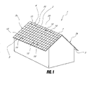
- FIG. 1 shows a building 1 with a roof 2 according to one embodiment.
- the roof 2 comprises two fields 3 a and 3 b that are joined at their upper ends to define a ridge 4 . Lower edges 5 of the fields are referred to as “eaves.”
- the fields 3 a and 3 b comprise a roof supporting structure (not shown) covered with tiles 20 (e.g., clay or concrete).
- the roof is suitable for having one or more vent tiles 10 according to one embodiment of the invention. Also, skilled artisans will appreciate that the vent tiles may be provided in a wide variety of different types of roofs, including those not having ridges or sloped fields.
- a plurality of vent tiles 10 are lined up on the field 3 a along the ridge 4 and eave 5 of the roof 2 .
- the vent tiles 10 are preferably provided in each field 3 a , 3 b . In other embodiments, the vent tiles 10 may be positioned alternatively or additionally on different parts of the field 3 a , 3 b , depending on the ventilation
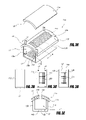
- FIG. 2 illustrates a portion of the roof 2 according to one embodiment.
- the illustrated portion of the roof 2 includes roof tiles 20 supported by a roof supporting structure 30 .
- Some of the roof tiles 20 comprise the aforementioned vent tiles 10 .
- the reference numeral 20 refers to roof tiles that are not vent tiles 10 , unless otherwise indicated. However, it should be understood that each vent tile 10 is preferably a specialized roof tile 20 .
- the roof tiles 20 are arranged in columns and rows.
- the vent tiles 10 are positioned between two of the roof tiles 20 both in the horizontal direction and in the vertical direction. It will be appreciated that the positions of the vent tiles 10 may vary depending on the ventilation needs.
- the roof supporting structure 30 supports both the vent tiles 10 and the roof tiles 20 .
- each roof tile 20 includes a cap section 20 a and a pan section 20 b .
- the tiles' cap sections 20 a form cap columns, and the tiles' pan sections 20 b form pan channels. Rainwater tends to flow downward within the pan channels.
- each roof tile 20 includes two or more cap sections 20 a and two or more corresponding pan sections 20 b .
- the vent tiles 10 preferably have the same number of cap sections 10 a and pan sections 10 b as the roof tiles 20 , preferably in the same size and shape so as to blend in visually and functionally with the roof tiles 20 .
- a cap section 10 a of a vent tile 10 includes a first upper plate 11 a , a second upper plate 11 b , spacers 16 , a lower plate 12 , and sidewalls 13 .
- the first upper plate 11 a covers the second upper plate 11 b with a gap therebetween.
- the second upper plate 11 b opposes the lower plate 12 with a space therebetween.
- the sidewalls 13 include a first sidewall 13 a and a second sidewall 13 b opposing each other.
- the second upper plate 11 b , the lower plate 12 , and the two sidewalls 13 a , 13 b together define a channel 17 formed through the cap section 10 a of the vent tile 10 . While not shown in FIG.
- a pan section can be attached or formed integrally with one of the sidewalls 13 a , 13 b .
- the vent tile 10 can include any number of cap sections and pan sections, preferably matching the number, size, and shape of cap and pan sections of the roof tile 20 .
- the first upper plate 11 a forms a cover of the cap section 10 a of the vent tile 10 .
- the illustrated first upper plate 11 a is convex when viewed from above. In other embodiments, the first upper plate may have various other shapes and configurations.
- the first upper plate 11 a may be formed of, without limitation, a metal, clay, a plastic material, or a combination of two or more of the foregoing.
- first upper plate 11 a may have a downwardly depending baffle or flange 18 at its lower edge.
- the flange 18 may be configured to allow airflow underneath it while preventing ingress of rain or snow.
- the second upper plate 11 b forms an upper part of the cap section 10 a of the vent tile 10 .
- the illustrated second upper plate 11 b is shaped substantially similar or in conformity with the first upper plate 11 a .
- the second upper plate may have various other shapes and configurations.
- the second upper plate 11 b may be formed of, without limitation, a metal, clay, a plastic material, or a combination of two or more of the foregoing.
- the second upper plate 11 b has a first opening 14 a penetrating therethrough.
- the first opening 14 a permits airflow between the channel 17 and a region above the vent tile 10 , as will be better understood from later description herein.
- the first opening 14 a may include louvers.
- the louvers include a number of narrow slits formed in parallel to one another. It will be appreciated that the shape, number, and position of the slits can be varied, depending on the design of a vent tile.
- the first opening 14 a may be covered by a screen 15 a to prevent entry of insects, vermin, and debris larger than the screen openings ( FIG. 3C ).
- the spacers 16 provide a gap between the first and second upper plates 11 a , 11 b , thereby forming a ventilating access therebetween.
- the spacers 16 support the first upper plate 11 a above the second upper plate 11 b , forming a space throughout between the upper plates 11 a , 11 b .
- This configuration provides ventilating access in all directions from the cap section 10 a of the vent tile 10 .
- the ventilating access may be limited to a certain direction(s) from the cap section 10 a of the vent tile 10 , e.g., down, left or right.
- the configuration of the spacers 16 can be adapted to the design of the ventilating access.
- the spacers 16 may be attached to the first and second upper plates 11 a , 11 b in any suitable manner. In certain embodiments, the spacers 16 may be formed integrally with one or both of the upper plates 11 a , 11 b .
- the spacers 16 may be formed of, without limitation, a metal, a plastic material, or a combination of the foregoing.
- the lower plate 12 forms a lower part of the cap section 10 a of the vent tile 10 .
- the illustrated lower plate 12 is flat in shape. In other embodiments, the lower plate may have various other shapes.
- the lower plate 12 may be formed of, without limitation, a metal, clay, a plastic material, or a combination of two or more of the foregoing. Preferably, the lower plate 12 is formed of the same material as that of the upper plates 11 a , 11 b.
- the lower plate 12 has a second opening 14 b penetrating therethrough.
- the second opening 14 b permits airflow between the channel 17 and a region below the lower plate 12 .
- the illustrated second opening 14 b is covered by a screen 15 b to prevent entry of insects, vermin, and debris larger than the screen openings.
- the sidewalls 13 connect the second upper plate 11 b to the lower plate 12 .
- the sidewalls 13 are integrally formed with the second upper plate 11 b and the lower plate 12 .
- the sidewalls 13 may be secured to the second upper plate 11 b and the lower plate 12 , using any suitable securing means.
- the sidewalls 13 may be formed of, without limitation, a metal, clay, a plastic material, or a combination of two or more of the foregoing.
- the sidewalls 13 are formed of the same material as that of the second upper plate 11 b and/or the lower plate 12 .
- the sidewalls 13 , second upper plate 11 b , lower plate 12 , and adjoining pan section(s) and additional cap section(s) (if any) are formed of the same material.
- the channel 17 is in ventilating communication with the first and second openings 14 a , 14 b .
- the gap between the first and second upper plates 11 a , 11 b is in ventilating communication with the first opening 14 a .
- This configuration permits airflow between regions above and below the roof 2 .
- the regions below the roof 2 may include an attic or a living space of a building.
- the channel 17 is also configured to be in ventilating communication with air channels of the roof tiles 20 , as will be better understood from later description herein.
- each of cap sections 20 a of the roof tiles 20 includes an upper plate 21 , a lower plate 22 , and sidewalls 23 .
- the upper plate 21 opposes the lower plate 22 with a space therebetween.
- the sidewalls 23 include a first sidewall 23 a and a second sidewall 23 b opposing each other.
- the upper plate 21 , the lower plate 22 , and the two sidewalls 23 a , 23 b together define an air channel 27 formed through the cap section 20 a of the roof tile 20 .
- the upper plate 21 forms an upper part of the cap section 20 a of the roof tile 20 .
- the illustrated upper plate 21 is convex when viewed from above. In other embodiments, the upper plate may have various other shapes.
- the upper plate 21 of the cap section 20 a of the roof tile 20 has substantially the same shape as the first upper plate 11 a of the cap section 10 a of the vent tile 10 .
- the upper plate 21 may be formed of, without limitation, clay, a metal, a plastic material, or a combination of two or more of the foregoing.
- the upper plate 21 is formed of clay.
- the lower plate 22 forms a lower part of the cap section 20 a of the roof tile 20 .
- the illustrated lower plate 22 is flat in shape. In other embodiments, the lower plate may have various other shapes.
- the lower plate 22 may be formed of, without limitation, clay, a metal, a plastic material, or a combination of two or more of the foregoing. Preferably, the lower plate 22 is formed of the same material as that of the upper plate 21 .
- the sidewalls 23 connect the upper plate 21 to the lower plate 22 .
- the sidewalls 23 are integrally formed with the upper and lower plates 21 , 22 .
- the sidewalls 23 may be secured to the upper and lower plates 21 , 22 , using any suitable securing means.
- the sidewalls 23 may be formed of, without limitation, clay, a metal, a plastic material, or a combination of two or more of the foregoing.
- the sidewalls 23 are formed of the same material as that of the upper plate 21 or the lower plate 22 .
- the upper plate 21 , lower plate 22 , and sidewalls 23 are formed of the same material.
- FIG. 4A illustrates a cross-section of the roof 2 of FIG. 2 , taken along the line 4 A- 4 A.
- the roof tiles 20 are arranged parallel to one another on the roof supporting structure 30 .
- the vent tiles 10 are interposed between two of the roof tiles 20 in the illustrated cross-section.
- the first and second openings 14 a , 14 b of the vent tiles 10 are in ventilating communication with apertures 35 of the roof supporting structure 30 .
- the ventilating access between the first and second upper plates 11 a , 11 b is in ventilating communication with the first opening 14 a of the second upper plate 11 b .
- This configuration permits airflow between regions above and below the roof 2 , and thus reduces heat or moisture build-up in the regions below the roof 2 .
- the regions below the roof 2 may include an attic or a living space of a building.
- FIG. 4B is a cross-section of the roof 2 of FIG. 2 , taken along the line 4 B- 4 B.
- the roof tiles 20 are arranged in lines (or “columns” or “groups”) extending between the eave and ridge (not shown) of the roof 2 .
- the roof tiles 20 are arranged such that the air channels 27 of the roof tiles 20 of each aligned group of roof tiles are in ventilating communication with one another to collectively form air passages extending within the roof.
- the air channels 27 are optionally located within the cap sections 20 a of the roof tiles 20 . This configuration provides insulation throughout the roof 2 .
- one or more of the roof tiles 20 in each aligned group of roof tiles 20 is replaced by a vent tile 10 .
- the air channels 27 of the roof tiles 20 are also in ventilating communication with the first opening 14 a and second opening 14 b of the vent tile 10 .
- This configuration permits ventilation of the air channels 27 of the roof tiles 20 .
- the ventilation of the air channels 27 facilitates ventilation of the building while preserving the insulative effect of the air passages, each of which is defined by a group of air channels 27 (of roof tiles 20 ) and one or more air channels 17 (of vent tiles 10 ).
- the vent tile 10 is positioned vertically between two of the roof tiles 20 .
- the vent tile 10 may be located near the eave or ridge of the roof, as shown in FIG. 1 , and may have only one neighboring roof tile 20 .
- two or more vent tiles 10 may be provided in an aligned group or column of roof tiles 20 .
- the vent tiles 10 may be provided in every aligned group or column of roof tiles 20 throughout the roof.
- the vent tiles 10 may be provided in every other aligned group or column of roof tiles 20 .
- a skilled artisan will appreciate that the number and positions of the vent tiles 10 may vary depending on the ventilation needs.
- cap sections 10 a of the vent tiles 10 and cap sections 20 b of the roof tiles 20 can be positioned between pan sections 10 b , 20 b . More specifically, each pan section 10 b can be positioned between two cap sections 10 a or between a cap section 10 a and a cap section 20 a , and each pan section 20 b can be positioned between two cap sections 20 a or between a cap section 20 a and a cap section 10 a .
- the illustrated pan section 10 b , 20 b includes an upper plate 41 , a lower plate 42 , and a central wall 48 , but other configurations are possible.
- the illustrated upper plate 41 is concave when viewed from above.
- the lower plate 42 is flat in shape.
- the central wall 48 connects the upper plate 41 with the lower plate 42 .
- the upper plate 41 , the lower plate 42 , and the central wall 48 together define air channels 47 .
- These air channels 47 can be in ventilating communication with the air channels 47 of a neighboring roof tile (not shown). This configuration provides further insulation of the roof.
- FIG. 5A illustrates one embodiment of a roof tile 520 having two cap sections 501 and two pan sections 502 .
- the cap sections 501 and the pan sections 502 may be all integrated with one another, forming a single piece, and are preferably formed integrally. They may be fixed to one another using any suitable fastening means. Examples of the fastening means include, but are not limited to, bolts, nuts, nails, screws, adhesives, and solder. This combined structure permits ease of handling and installing. In other embodiments, however, the cap sections 501 and the pan sections 502 may be provided separately. A skilled artisan will appreciate that various configurations of tile structures are possible.
- FIGS. 5B-5C illustrate various embodiments of vent tiles 510 B, 510 C, 510 D configured to blend in visually and functionally with the roof tile 520 of FIG. 5A .
- Each of the vent tiles 510 B, 510 C, 510 D has two cap sections 501 , 503 and two pan sections 502 .
- the cap sections 501 , 503 and the pan sections 502 may be all integrated with one another, forming a single piece, and are preferably formed integrally.
- the vent tile 510 B of FIG. 5B includes two ventilating cap sections 503 and two pan sections 502 .
- the vent tile 510 C of FIG. 5C includes one non-ventilating cap section 501 , one ventilating cap section 503 , and two pan sections 502 .
- the vent tile 510 D of FIG. 5D also includes one non-ventilating cap section 501 , one ventilating cap section 503 , and two pan sections 502 .
- the ventilating cap section 503 and the non-ventilating cap section 501 of the vent tile 510 D have an opposite arrangement from those of the vent tile 510 C. It will be appreciated that various other configurations of vent tiles are possible.
- the vent tile 10 may have the same shape as that of the roof tiles 20 .
- the vent tile 10 preferably mimics the appearance of the roof tiles 20 . This configuration avoids detrimentally affecting the appearance of the roof.
- the vent tile may have a different shape and size to meet ventilation and/or decorative needs.
- a roof 600 A includes a roof supporting structure comprising a roof deck 30 .
- the illustrated roof deck 30 directly supports the vent tiles 10 and the roof tiles 20 .
- the roof deck 30 includes apertures 35 over which the vent tiles 10 are placed.
- the apertures 35 are in ventilating communication with the second openings 14 b of the vent tile lower plates 12 , as shown in FIG. 4A . This configuration permits airflow between regions above and below the roof 600 A.
- the roof supporting structure may further include battens interposed between the roof deck 30 and the tiles 10 , 20 .
- the battens may run parallel to one another and to the eave and ridge of the roof.
- the battens may directly support the tiles 10 , 20 .
- the battens are preferably configured to not interrupt the air passages collectively formed by the air channels 27 of the roof tiles 20 .
- the roof supporting structure may include rafters 60 and battens 50 without a roof deck.
- the battens 50 directly support the tiles 10 , 20 .
- no aperture is required in the roof supporting structure because the spaces between the battens are open for airflow.
- the roof supporting structure may also include a radiant barrier layer attached to either or both of the rafters and battens. The configuration of the radiant barrier layer may be as described above with reference to FIG. 6A .
- the roof tiles described above may be installed in a roof as follows.
- the vent tiles 10 are simply installed sequentially with the roof tiles 20 .
- the roof structure includes vent tiles mimicking the appearance of roof tiles. This configuration enhances the insulating of the roof without detrimentally affecting the appearance of the roof. It will be understood that the appearance of the vent tiles and roof tiles can be different than that of the tiles 10 , 20 disclosed herein.
Landscapes
- Engineering & Computer Science (AREA)
- Architecture (AREA)
- Civil Engineering (AREA)
- Structural Engineering (AREA)
- Chemical & Material Sciences (AREA)
- Ceramic Engineering (AREA)
- Building Environments (AREA)
Abstract
A roof ventilation for a roof having roof tiles with air channels is disclosed. The roof includes a roof supporting structure, a plurality of roof tiles, and at least one vent tile. The plurality of roof tiles reside over the roof supporting structure. The roof tiles include air channels formed therethrough which are in ventilating communication with one another. The least one vent tile resides over the roof supporting structure. Each of the at least one vent tile includes a first upper plate, a second upper plate, and a lower plate. The first and second upper plates are spaced apart from each other, forming a ventilating access. The second upper plate has a first opening and the lower plate has a second opening. The first opening is in ventilating communication with the second opening and with at least one of the air channels. The ventilating access and the first and second openings together permit airflow between regions above and below the roof. The at least one of the air channels is substantially aligned with a space between the upper and lower plates.
Description
- This application claims the priority benefit under 35 U.S.C. § 119(e) of Provisional Application Ser. No. 60/856,223, filed Nov. 1, 2006. The full disclosure of this priority application is incorporated herein by reference.
- 1. Field of the Invention
- This application relates generally to building ventilation and specifically to roof ventilation.
- 2. Description of the Related Art
- Energy efficiency is a serious consideration in building design. Buildings require ways to minimize energy requirements to maintain comfortable living spaces. Certain buildings have a roof and an attic underneath the roof. One of the most common energy losses in such buildings is due to heat transfer through the attic. In warm climates, heat builds up in the attic from solar energy incident on the roof. In colder climates, moisture builds up in the attic, robbing the insulation of much of its R value.
- Recently, ventilation systems have been incorporated to enhance the insulation of a roof. Such ventilation systems remove heat and/or moisture build-up in the attic, thus minimizing energy losses due to heat transfer through the attic.
- Certain buildings include a roof with roof tiles having air channels. The air channels are formed through the roof tiles, and are in ventilating communication with one another. The air channels provide insulation between regions above and below the roof. Such buildings, however, may still have heat or moisture build-up in the attic. Therefore, there is still a need to provide a ventilation system that properly ventilates the attic. There is also a need to provide a ventilation system which minimally detrimentally affects the appearance of a roof design and is applicable to various types of roofs, while offering low installation costs relative to other ventilation systems.
- Preferred embodiments of the present invention provide a roof structure for a tiled roof of a building. In accordance with a preferred embodiment, a roof structure is provided comprising a roof supporting structure and a plurality of roof tiles over the roof supporting structure. Each of the roof tiles comprises an upper plate, a lower plate, and an air channel formed through the roof tile between the upper and lower plates. The roof tiles are arranged in a plurality of groups. The roof tiles and air channels of each group of roof tiles are adjacently positioned so that the air channels of each group are in ventilating communication with one another and collectively form an air passage within the roof. At least one of the roof tiles comprises a vent tile comprising a first upper plate, a second upper plate underlying the first upper plate, and a lower plate including a second opening. The first and second upper plates have a gap therebetween. The second upper plate includes a first opening. The lower plate is positioned below the second upper plate with an air channel defined therebetween. The first opening is in ventilating communication with the second opening via the air channel of the vent tile. The gap and the first and second openings together permit airflow between regions above and below the roof.
- In accordance with another preferred embodiment, a vent tile is provided comprising a first upper plate, a second upper plate underlying the first upper plate, a lower plate opposing the second upper plate, and sidewalls connecting the second upper plate to the lower plate. The first and second upper plates have a gap therebetween. The second upper plate includes a first opening. The lower plate includes a second opening. The second upper plate, the lower plate, and the sidewalls together define an air channel formed through the vent tile. The first and second openings are in ventilating communication with each other through the air channel.
- In accordance with yet another preferred embodiment, a method of providing a roof structure for a tiled roof of a building is provided. The method comprises providing a roof supporting structure. Then, a plurality of roof tiles are provided over the roof supporting structure. In addition, each of the roof tiles comprises an upper plate, a lower plate, and an air channel formed through the roof tile between the upper and lower plates. The roof tiles are arranged in a plurality of groups. The roof tiles and air channels of each group of roof tiles are adjacently positioned so that the air channels of each group are in ventilating communication with one another and collectively form an air passage within the roof. Providing at least one of the roof tiles comprises providing a vent tile comprising a first upper plate, a second upper plate underlying the first upper plate, and a lower plate including a second opening. The first and second upper plates have a gap therebetween. The second upper plate includes a first opening. The lower plate is positioned below the second upper plate with an air channel defined therebetween. The first opening is in ventilating communication with the second opening via the air channel of the vent tile. The gap and the first and second openings together permit airflow between regions above and below the roof.
- For purposes of summarizing the invention and the advantages achieved over the prior art, certain objects and advantages of the invention have been described above and as further described below. Of course, it is to be understood that not necessarily all such objects or advantages may be achieved in accordance with any particular embodiment of the invention. Thus, for example, those skilled in the art will recognize that the invention may be embodied or carried out in a manner that achieves or optimizes one advantage or group of advantages as taught herein without necessarily achieving other objects or advantages as may be taught or suggested herein.
- All of these embodiments are intended to be within the scope of the invention herein disclosed. These and other embodiments of the present invention will become readily apparent to those skilled in the art from the following detailed description of the preferred embodiments having reference to the attached figure, the invention not being limited to any particular preferred embodiment(s) disclosed.
-
FIG. 1 is a perspective view of a building with a tiled roof having vent tiles in accordance with one embodiment of the present invention; -
FIG. 2 is a perspective view of one embodiment of a roof structure having vent tiles; -
FIG. 3A is an exploded perspective view of one embodiment of a cap section of a vent tile; -
FIG. 3B is a top plan view of the cap section of the vent tile ofFIG. 3A ; -
FIG. 3C is a top plan view of the second upper plate of the cap section of the vent tile ofFIG. 3A ; -
FIG. 3D is a cross-sectional view of the cap section of the vent tile ofFIG. 3A , taken along theline 3D-3D; -
FIG. 3E is a cross-sectional view of the cap section of the vent tile ofFIG. 3A , taken along theline 3E-3E; -
FIG. 4A is a cross-sectional view of the roof structure ofFIG. 2 , taken along theline 4A-4A; -
FIG. 4B is a cross-sectional view of the roof structure ofFIG. 2 , taken along theline 4B-4B; -
FIG. 5A is a cross-sectional view of one embodiment of a roof tile. -
FIGS. 5B-5D are cross-sectional views of embodiments of vent tiles. -
FIG. 6A is a perspective view of another embodiment of a roof structure having a vent tile; and -
FIG. 6B is a perspective view of yet another embodiment of a roof structure having a vent tile. -
FIG. 1 shows a building 1 with aroof 2 according to one embodiment. Theroof 2 comprises twofields fields more vent tiles 10 according to one embodiment of the invention. Also, skilled artisans will appreciate that the vent tiles may be provided in a wide variety of different types of roofs, including those not having ridges or sloped fields. InFIG. 1 , a plurality ofvent tiles 10 are lined up on thefield 3 a along the ridge 4 andeave 5 of theroof 2. Thevent tiles 10 are preferably provided in eachfield vent tiles 10 may be positioned alternatively or additionally on different parts of thefield -
FIG. 2 illustrates a portion of theroof 2 according to one embodiment. The illustrated portion of theroof 2 includesroof tiles 20 supported by aroof supporting structure 30. Some of theroof tiles 20 comprise theaforementioned vent tiles 10. As used herein, thereference numeral 20 refers to roof tiles that are not venttiles 10, unless otherwise indicated. However, it should be understood that eachvent tile 10 is preferably aspecialized roof tile 20. Theroof tiles 20 are arranged in columns and rows. Thevent tiles 10 are positioned between two of theroof tiles 20 both in the horizontal direction and in the vertical direction. It will be appreciated that the positions of thevent tiles 10 may vary depending on the ventilation needs. Theroof supporting structure 30 supports both thevent tiles 10 and theroof tiles 20. - In
FIG. 2 , eachroof tile 20 includes acap section 20 a and apan section 20 b. When thetiles 20 are assembled, the tiles'cap sections 20 a form cap columns, and the tiles'pan sections 20 b form pan channels. Rainwater tends to flow downward within the pan channels. In an alternative embodiment, eachroof tile 20 includes two ormore cap sections 20 a and two or morecorresponding pan sections 20 b. Thevent tiles 10 preferably have the same number ofcap sections 10 a andpan sections 10 b as theroof tiles 20, preferably in the same size and shape so as to blend in visually and functionally with theroof tiles 20. - Referring to
FIG. 3A , acap section 10 a of avent tile 10 includes a firstupper plate 11 a, a secondupper plate 11 b,spacers 16, alower plate 12, and sidewalls 13. The firstupper plate 11 a covers the secondupper plate 11 b with a gap therebetween. The secondupper plate 11 b opposes thelower plate 12 with a space therebetween. The sidewalls 13 include afirst sidewall 13 a and asecond sidewall 13 b opposing each other. The secondupper plate 11 b, thelower plate 12, and the twosidewalls channel 17 formed through thecap section 10 a of thevent tile 10. While not shown inFIG. 3A , a pan section can be attached or formed integrally with one of the sidewalls 13 a, 13 b. Also, thevent tile 10 can include any number of cap sections and pan sections, preferably matching the number, size, and shape of cap and pan sections of theroof tile 20. - The first
upper plate 11 a forms a cover of thecap section 10 a of thevent tile 10. The illustrated firstupper plate 11 a is convex when viewed from above. In other embodiments, the first upper plate may have various other shapes and configurations. The firstupper plate 11 a may be formed of, without limitation, a metal, clay, a plastic material, or a combination of two or more of the foregoing. - In addition, the first
upper plate 11 a may have a downwardly depending baffle orflange 18 at its lower edge. Theflange 18 may be configured to allow airflow underneath it while preventing ingress of rain or snow. - The second
upper plate 11 b forms an upper part of thecap section 10 a of thevent tile 10. The illustrated secondupper plate 11 b is shaped substantially similar or in conformity with the firstupper plate 11 a. In other embodiments, the second upper plate may have various other shapes and configurations. The secondupper plate 11 b may be formed of, without limitation, a metal, clay, a plastic material, or a combination of two or more of the foregoing. - The second
upper plate 11 b has afirst opening 14 a penetrating therethrough. Thefirst opening 14 a permits airflow between thechannel 17 and a region above thevent tile 10, as will be better understood from later description herein. In certain embodiments, thefirst opening 14 a may include louvers. The louvers include a number of narrow slits formed in parallel to one another. It will be appreciated that the shape, number, and position of the slits can be varied, depending on the design of a vent tile. Thefirst opening 14 a may be covered by ascreen 15 a to prevent entry of insects, vermin, and debris larger than the screen openings (FIG. 3C ). - Referring to
FIG. 3E , thespacers 16 provide a gap between the first and secondupper plates spacers 16 support the firstupper plate 11 a above the secondupper plate 11 b, forming a space throughout between theupper plates cap section 10 a of thevent tile 10. In other embodiments, the ventilating access may be limited to a certain direction(s) from thecap section 10 a of thevent tile 10, e.g., down, left or right. A skilled artisan will appreciate that the configuration of thespacers 16 can be adapted to the design of the ventilating access. Thespacers 16 may be attached to the first and secondupper plates spacers 16 may be formed integrally with one or both of theupper plates spacers 16 may be formed of, without limitation, a metal, a plastic material, or a combination of the foregoing. - The
lower plate 12 forms a lower part of thecap section 10 a of thevent tile 10. The illustratedlower plate 12 is flat in shape. In other embodiments, the lower plate may have various other shapes. Thelower plate 12 may be formed of, without limitation, a metal, clay, a plastic material, or a combination of two or more of the foregoing. Preferably, thelower plate 12 is formed of the same material as that of theupper plates - Referring to
FIGS. 3D and 3E , thelower plate 12 has asecond opening 14 b penetrating therethrough. Thesecond opening 14 b permits airflow between thechannel 17 and a region below thelower plate 12. Referring toFIG. 3D , the illustratedsecond opening 14 b is covered by ascreen 15 b to prevent entry of insects, vermin, and debris larger than the screen openings. - The sidewalls 13 connect the second
upper plate 11 b to thelower plate 12. In the illustrated embodiment, the sidewalls 13 are integrally formed with the secondupper plate 11 b and thelower plate 12. The sidewalls 13 may be secured to the secondupper plate 11 b and thelower plate 12, using any suitable securing means. The sidewalls 13 may be formed of, without limitation, a metal, clay, a plastic material, or a combination of two or more of the foregoing. Preferably, the sidewalls 13 are formed of the same material as that of the secondupper plate 11 b and/or thelower plate 12. Preferably, the sidewalls 13, secondupper plate 11 b,lower plate 12, and adjoining pan section(s) and additional cap section(s) (if any) are formed of the same material. - The
channel 17, as shown inFIG. 3A , is in ventilating communication with the first andsecond openings upper plates first opening 14 a. This configuration permits airflow between regions above and below theroof 2. The regions below theroof 2 may include an attic or a living space of a building. Thechannel 17 is also configured to be in ventilating communication with air channels of theroof tiles 20, as will be better understood from later description herein. - Referring to
FIG. 4A , each ofcap sections 20 a of theroof tiles 20 includes anupper plate 21, alower plate 22, and sidewalls 23. Theupper plate 21 opposes thelower plate 22 with a space therebetween. The sidewalls 23 include a first sidewall 23 a and asecond sidewall 23 b opposing each other. Theupper plate 21, thelower plate 22, and the twosidewalls 23 a, 23 b, together define anair channel 27 formed through thecap section 20 a of theroof tile 20. - The
upper plate 21 forms an upper part of thecap section 20 a of theroof tile 20. The illustratedupper plate 21 is convex when viewed from above. In other embodiments, the upper plate may have various other shapes. Preferably, theupper plate 21 of thecap section 20 a of theroof tile 20 has substantially the same shape as the firstupper plate 11 a of thecap section 10 a of thevent tile 10. Theupper plate 21 may be formed of, without limitation, clay, a metal, a plastic material, or a combination of two or more of the foregoing. Preferably, theupper plate 21 is formed of clay. - The
lower plate 22 forms a lower part of thecap section 20 a of theroof tile 20. The illustratedlower plate 22 is flat in shape. In other embodiments, the lower plate may have various other shapes. Thelower plate 22 may be formed of, without limitation, clay, a metal, a plastic material, or a combination of two or more of the foregoing. Preferably, thelower plate 22 is formed of the same material as that of theupper plate 21. - The sidewalls 23 connect the
upper plate 21 to thelower plate 22. In the illustrated embodiment, the sidewalls 23 are integrally formed with the upper andlower plates lower plates upper plate 21 or thelower plate 22. Preferably, theupper plate 21,lower plate 22, and sidewalls 23 are formed of the same material. -
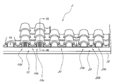
FIG. 4A illustrates a cross-section of theroof 2 ofFIG. 2 , taken along theline 4A-4A. Theroof tiles 20 are arranged parallel to one another on theroof supporting structure 30. Thevent tiles 10 are interposed between two of theroof tiles 20 in the illustrated cross-section. Referring to the embodiment ofFIG. 4A , the first andsecond openings vent tiles 10 are in ventilating communication withapertures 35 of theroof supporting structure 30. In addition, the ventilating access between the first and secondupper plates first opening 14 a of the secondupper plate 11 b. This configuration permits airflow between regions above and below theroof 2, and thus reduces heat or moisture build-up in the regions below theroof 2. The regions below theroof 2 may include an attic or a living space of a building. -
FIG. 4B is a cross-section of theroof 2 ofFIG. 2 , taken along theline 4B-4B. In this embodiment, theroof tiles 20 are arranged in lines (or “columns” or “groups”) extending between the eave and ridge (not shown) of theroof 2. Theroof tiles 20 are arranged such that theair channels 27 of theroof tiles 20 of each aligned group of roof tiles are in ventilating communication with one another to collectively form air passages extending within the roof. As described above, theair channels 27 are optionally located within thecap sections 20 a of theroof tiles 20. This configuration provides insulation throughout theroof 2. Preferably, one or more of theroof tiles 20 in each aligned group ofroof tiles 20 is replaced by avent tile 10. Thus, theair channels 27 of theroof tiles 20 are also in ventilating communication with thefirst opening 14 a andsecond opening 14 b of thevent tile 10. This configuration permits ventilation of theair channels 27 of theroof tiles 20. The ventilation of theair channels 27 facilitates ventilation of the building while preserving the insulative effect of the air passages, each of which is defined by a group of air channels 27 (of roof tiles 20) and one or more air channels 17 (of vent tiles 10). - In
FIG. 4B , thevent tile 10 is positioned vertically between two of theroof tiles 20. In another embodiment, thevent tile 10 may be located near the eave or ridge of the roof, as shown inFIG. 1 , and may have only one neighboringroof tile 20. In certain embodiments, two ormore vent tiles 10 may be provided in an aligned group or column ofroof tiles 20. Thevent tiles 10 may be provided in every aligned group or column ofroof tiles 20 throughout the roof. In another embodiment, thevent tiles 10 may be provided in every other aligned group or column ofroof tiles 20. A skilled artisan will appreciate that the number and positions of thevent tiles 10 may vary depending on the ventilation needs. - Referring back to
FIG. 4A ,cap sections 10 a of thevent tiles 10 andcap sections 20 b of theroof tiles 20 can be positioned betweenpan sections pan section 10 b can be positioned between twocap sections 10 a or between acap section 10 a and acap section 20 a, and eachpan section 20 b can be positioned between twocap sections 20 a or between acap section 20 a and acap section 10 a. The illustratedpan section upper plate 41, alower plate 42, and acentral wall 48, but other configurations are possible. The illustratedupper plate 41 is concave when viewed from above. Thelower plate 42 is flat in shape. Thecentral wall 48 connects theupper plate 41 with thelower plate 42. Theupper plate 41, thelower plate 42, and thecentral wall 48 together defineair channels 47. Theseair channels 47 can be in ventilating communication with theair channels 47 of a neighboring roof tile (not shown). This configuration provides further insulation of the roof. -
FIG. 5A illustrates one embodiment of aroof tile 520 having twocap sections 501 and twopan sections 502. Thecap sections 501 and thepan sections 502 may be all integrated with one another, forming a single piece, and are preferably formed integrally. They may be fixed to one another using any suitable fastening means. Examples of the fastening means include, but are not limited to, bolts, nuts, nails, screws, adhesives, and solder. This combined structure permits ease of handling and installing. In other embodiments, however, thecap sections 501 and thepan sections 502 may be provided separately. A skilled artisan will appreciate that various configurations of tile structures are possible. -
FIGS. 5B-5C illustrate various embodiments ofvent tiles roof tile 520 ofFIG. 5A . Each of thevent tiles cap sections pan sections 502. Thecap sections pan sections 502 may be all integrated with one another, forming a single piece, and are preferably formed integrally. - The
vent tile 510B ofFIG. 5B includes two ventilatingcap sections 503 and twopan sections 502. Thevent tile 510C ofFIG. 5C includes onenon-ventilating cap section 501, oneventilating cap section 503, and twopan sections 502. Thevent tile 510D ofFIG. 5D also includes onenon-ventilating cap section 501, oneventilating cap section 503, and twopan sections 502. Theventilating cap section 503 and thenon-ventilating cap section 501 of thevent tile 510D, however, have an opposite arrangement from those of thevent tile 510C. It will be appreciated that various other configurations of vent tiles are possible. - The
vent tile 10, as shown inFIGS. 2-5 , may have the same shape as that of theroof tiles 20. Thevent tile 10 preferably mimics the appearance of theroof tiles 20. This configuration avoids detrimentally affecting the appearance of the roof. In another embodiment, however, the vent tile may have a different shape and size to meet ventilation and/or decorative needs. - The roof supporting structure supports both the
vent tiles 10 and theroof tiles 20. Referring toFIG. 6A , aroof 600A includes a roof supporting structure comprising aroof deck 30. The illustratedroof deck 30 directly supports thevent tiles 10 and theroof tiles 20. In this embodiment, theroof deck 30 includesapertures 35 over which thevent tiles 10 are placed. Theapertures 35 are in ventilating communication with thesecond openings 14 b of the vent tilelower plates 12, as shown inFIG. 4A . This configuration permits airflow between regions above and below theroof 600A. - In another embodiment, the roof supporting structure may further include battens interposed between the
roof deck 30 and thetiles tiles air channels 27 of theroof tiles 20. - In certain embodiments, the roof supporting structure may also include a radiant barrier layer. The radiant barrier layer may reside over and substantially across the roof supporting structure. The radiant barrier layer includes a radiant barrier material that reflects radiant heat away from the roof. The radiant barrier material may comprise a sheet or coating. The coating may be formed of a paint blended with a radiant barrier additive. The radiant barrier material may preferably include a highly reflective material, such as aluminum. The radiant barrier layer may further include a substrate material such as kraft paper, plastic films (e.g., polypropylene and polyethylene), or cardboard. Another type of radiant barrier layer comprises bubble wrap with one or both sides covered with aluminum foil. In certain embodiments, the radiant barrier layer is reinforced by fiber to increase the durability and ease of handling. The radiant barrier may also include apertures in ventilating communication with the apertures of the
roof deck 30 and thesecond openings 14 b of the vent tilelower plates 12. - Referring to
FIG. 6B , the roof supporting structure may includerafters 60 and battens 50 without a roof deck. Thebattens 50 directly support thetiles FIG. 6A . - The roof tiles described above (e.g., 10, 20) may be installed in a roof as follows. In one embodiment where the roof supporting structure has only rafters and battens without a roof deck or a radiant barrier, the
vent tiles 10 are simply installed sequentially with theroof tiles 20. - In another embodiment where the roof supporting structure comprises a roof deck and/or a radiant barrier layer, apertures (e.g., 35) are formed through the deck and/or the radiant barrier layer. Then, the
roof tiles 20 and venttiles 10 are mounted thereon. Thevent tiles 10 are installed at the apertures such that thesecond openings 14 b of the vent tilelower plates 12 are aligned with the apertures. A skilled artisan will appreciate that various other steps or processes may be used for installing theroof tiles 20 and thevent tiles 10. - According to the embodiments described above, the roof structure includes vent tiles mimicking the appearance of roof tiles. This configuration enhances the insulating of the roof without detrimentally affecting the appearance of the roof. It will be understood that the appearance of the vent tiles and roof tiles can be different than that of the
tiles - Although this invention has been disclosed in the context of certain preferred embodiments and examples, it will be understood by those skilled in the art that the present invention extends beyond the specifically disclosed embodiments to other alternative embodiments and/or uses of the invention and obvious modifications thereof. Thus, it is intended that the scope of the present invention herein disclosed should not be limited by the particular disclosed embodiments described above, but should be determined only by a fair reading of the claims that follow.
Claims (25)
1. A roof structure for a tiled roof of a building, the structure comprising:
a roof supporting structure; and
a plurality of roof tiles over the roof supporting structure, each of the roof tiles comprising an upper plate, a lower plate, and an air channel formed through the roof tile between the upper and lower plates, the roof tiles being arranged in a plurality of groups, wherein the roof tiles and air channels of each group of roof tiles are adjacently positioned so that the air channels of each group are in ventilating communication with one another and collectively form an air passage within the roof;
wherein at least one of the roof tiles comprises a vent tile comprising:
a first upper plate;
a second upper plate underlying the first upper plate, the first and second upper plates having a gap therebetween, the second upper plate including a first opening; and
a lower plate including a second opening, the lower plate positioned below the second upper plate with an air channel defined therebetween, the first opening being in ventilating communication with the second opening via the air channel of the vent tile, wherein the gap and the first and second openings together permit airflow between regions above and below the roof.
2. The structure of claim 1 , wherein the roof tiles and air channels of a first of the groups of roof tiles are substantially aligned, and wherein one of the roof tiles of the first group of roof tiles comprises the vent tile.
3. The structure of claim 2 , wherein the roof tiles of the first group are substantially aligned in a direction extending substantially parallel to a ridge of the roof.
4. The structure of claim 2 , wherein the roof tiles of the first group are substantially aligned in a direction extending substantially perpendicular to a ridge of the roof.
5. The structure of claim 2 , wherein the vent tile is interposed between two of the roof tiles of the first group of roof tiles.
6. The structure of claim 2 , wherein the vent tile is positioned at an end of the first group of roof tiles.
7. The structure of claim 2 , wherein the air passage of the first group of roof tiles substantially extends from a ridge to an eave of the roof.
8. The structure of claim 7 , wherein the vent tile of the first group is located near one of the ridge and the eave of the roof.
9. The structure of claim 7 , wherein an end of the air passage of the first group is open at the eave of the roof to an exterior of the building.
10. The structure of claim 1 , wherein the roof tiles cover substantially the entire roof supporting structure, and wherein the air passages of the groups of roof tiles are formed throughout the roof.
11. The structure of claim 1 , wherein the roof supporting structure comprises battens supporting the roof tiles.
12. The structure of claim 1 , wherein the roof supporting structure comprises a roof deck supporting the roof tiles, and wherein the roof deck has an aperture in ventilating communication with the second opening of the vent tile.
13. The structure of claim 1 , wherein the first opening comprises louvers in the second upper plate.
14. The structure of claim 1 , wherein the vent tile further comprises a screen covering at least one of the first and second openings.
15. The structure of claim 1 , wherein the vent tile comprises a metal.
16. The structure of claim 1 , wherein the vent tile comprises a material the same as that of the roof tiles that are not vent tiles.
17. The structure of claim 1 , wherein the vent tile has substantially the same shape as that of the roof tiles that are not vent tiles.
18. The structure of claim 1 , wherein the vent tile mimics an appearance of the roof tiles that are not vent tiles.
19. The structure of claim 1 , wherein the plurality of roof tiles comprise at least one roof tile comprising at least one cap section and at least one pan section, and wherein the vent tile includes the same number of cap sections and pan sections as the at least one roof tile.
20. The structure of claim 19 , wherein the first upper plate, the second upper plate, and the lower plate of the vent tile together resemble one of the at least one cap section of the at least one roof tile.
21. A vent tile comprising:
a first upper plate;
a second upper plate underlying the first upper plate, the first and second upper plates having a gap therebetween, the second upper plate including a first opening;
a lower plate opposing the second upper plate, the lower plate including a second opening; and
sidewalls connecting the second upper plate to the lower plate,
wherein the second upper plate, the lower plate, and the sidewalls together define an air channel formed through the vent tile, and
wherein the first and second openings are in ventilating communication with each other through the air channel.
22. The vent tile of claim 21 , further comprising at least one spacer interposed between the first and second upper plates.
23. A method of providing a roof structure for a tiled roof of a building, the method comprising:
providing a roof supporting structure;
providing a plurality of roof tiles over the roof supporting structure, each of the roof tiles comprising an upper plate, a lower plate, and an air channel formed through the roof tile between the upper and lower plates;
arranging the roof tiles in a plurality of groups; and
adjacently positioning the roof tiles and air channels of each group so that the air channels of each group are in ventilating communication with one another and collectively form an air passage within the roof,
wherein providing the plurality of the roof tiles comprises providing a vent tile comprising:
a first upper plate;
a second upper plate underlying the first upper plate, the first and second upper plates having a gap therebetween, the second upper plate including a first opening; and
a lower plate including a second opening, the lower plate positioned below the second upper plate with an air channel defined therebetween, the first opening being in ventilating communication with the second opening via the air channel of the vent tile, wherein the gap and the first and second openings together permit airflow between regions above and below the roof.
24. The method of claim 23 , wherein adjacently positioning the roof tiles and air channels of each group comprises substantially aligning the roof tiles of a first group of roof tiles, and wherein one of the roof tiles of the first group of roof tiles comprises the vent tile.
25. The method of claim 23 , wherein the vent tile has substantially the same shape as that of the roof tiles that are not vent tiles.
Priority Applications (1)
| Application Number | Priority Date | Filing Date | Title |
|---|---|---|---|
| US11/932,980 US20080098674A1 (en) | 2006-11-01 | 2007-10-31 | Roof ventilation system for tiled roof |
Applications Claiming Priority (2)
| Application Number | Priority Date | Filing Date | Title |
|---|---|---|---|
| US85622306P | 2006-11-01 | 2006-11-01 | |
| US11/932,980 US20080098674A1 (en) | 2006-11-01 | 2007-10-31 | Roof ventilation system for tiled roof |
Publications (1)
| Publication Number | Publication Date |
|---|---|
| US20080098674A1 true US20080098674A1 (en) | 2008-05-01 |
Family
ID=39328474
Family Applications (1)
| Application Number | Title | Priority Date | Filing Date |
|---|---|---|---|
| US11/932,980 Abandoned US20080098674A1 (en) | 2006-11-01 | 2007-10-31 | Roof ventilation system for tiled roof |
Country Status (1)
| Country | Link |
|---|---|
| US (1) | US20080098674A1 (en) |
Cited By (11)
| Publication number | Priority date | Publication date | Assignee | Title |
|---|---|---|---|---|
| WO2012033816A1 (en) * | 2010-09-08 | 2012-03-15 | 3M Innovative Properties Company | Above-deck roof venting article |
| US20120279927A1 (en) * | 2001-02-16 | 2012-11-08 | Husson Jr Frank D | Solar water pasteurizer |
| WO2013096171A1 (en) * | 2011-12-22 | 2013-06-27 | 3M Innovative Properties Company | Above-deck roof venting article |
| US20140115980A1 (en) * | 2012-11-01 | 2014-05-01 | 3M Innovative Properties Company | Above-deck roof venting article |
| US20140311077A1 (en) * | 2013-03-14 | 2014-10-23 | Amir Firouz | Structural Component System |
| US20150337536A1 (en) * | 2014-05-22 | 2015-11-26 | Andreas Hieke | Multi-layered ventilation apparatus and methods of manufacturing thereof |
| US20170022702A1 (en) * | 2016-06-20 | 2017-01-26 | Michael Heinrichs | Air Vent |
| CN107246113A (en) * | 2017-06-28 | 2017-10-13 | 无锡威奥液压机电设备有限公司 | A kind of good roof building watt of air permeability |
| US9790687B1 (en) * | 2016-04-15 | 2017-10-17 | Masoud Valinejadshoubi | Roof system with energy efficient features |
| CN108868012A (en) * | 2018-08-29 | 2018-11-23 | 颜伟锦 | A kind of semicircular tile for building of scalability |
| US11466460B2 (en) * | 2013-11-22 | 2022-10-11 | Gregory S. Daniels | Roof vent for supporting an extension member |
Citations (4)
| Publication number | Priority date | Publication date | Assignee | Title |
|---|---|---|---|---|
| US5549513A (en) * | 1993-10-13 | 1996-08-27 | Monier Roof Tile Inc. | Roof ventilation device |
| US5766071A (en) * | 1996-10-15 | 1998-06-16 | Kirkwood; Howard G. | Venturi ventilation system for an angled tile roof and method therefor |
| US6491579B1 (en) * | 1992-08-04 | 2002-12-10 | O'hagin Harry T. | Roof ventilation system and method |
| US20070207725A1 (en) * | 2006-03-06 | 2007-09-06 | O'hagin Carolina | Apparatus and methods for ventilation of solar roof panels |
-
2007
- 2007-10-31 US US11/932,980 patent/US20080098674A1/en not_active Abandoned
Patent Citations (4)
| Publication number | Priority date | Publication date | Assignee | Title |
|---|---|---|---|---|
| US6491579B1 (en) * | 1992-08-04 | 2002-12-10 | O'hagin Harry T. | Roof ventilation system and method |
| US5549513A (en) * | 1993-10-13 | 1996-08-27 | Monier Roof Tile Inc. | Roof ventilation device |
| US5766071A (en) * | 1996-10-15 | 1998-06-16 | Kirkwood; Howard G. | Venturi ventilation system for an angled tile roof and method therefor |
| US20070207725A1 (en) * | 2006-03-06 | 2007-09-06 | O'hagin Carolina | Apparatus and methods for ventilation of solar roof panels |
Cited By (25)
| Publication number | Priority date | Publication date | Assignee | Title |
|---|---|---|---|---|
| US8960183B2 (en) * | 2001-02-16 | 2015-02-24 | Solar Solutions Llc | Solar water pasteurizer |
| US20120279927A1 (en) * | 2001-02-16 | 2012-11-08 | Husson Jr Frank D | Solar water pasteurizer |
| US20130217318A1 (en) * | 2010-09-08 | 2013-08-22 | 3M Innovative Properties Company | Above-deck roof venting article, system and methos |
| US9945127B2 (en) * | 2010-09-08 | 2018-04-17 | 3M Innovative Properties Company | Above-deck roof venting article, system and methods |
| EP2614191A4 (en) * | 2010-09-08 | 2014-06-25 | 3M Innovative Properties Co | Above-deck roof venting article |
| CN103080441A (en) * | 2010-09-08 | 2013-05-01 | 3M创新有限公司 | Above-deck roof venting article |
| WO2012033816A1 (en) * | 2010-09-08 | 2012-03-15 | 3M Innovative Properties Company | Above-deck roof venting article |
| US9228356B2 (en) | 2011-12-22 | 2016-01-05 | 3M Innovative Properties Company | Above-deck roof venting article |
| WO2013096171A1 (en) * | 2011-12-22 | 2013-06-27 | 3M Innovative Properties Company | Above-deck roof venting article |
| US20140115980A1 (en) * | 2012-11-01 | 2014-05-01 | 3M Innovative Properties Company | Above-deck roof venting article |
| US9228355B2 (en) * | 2012-11-01 | 2016-01-05 | 3M Innovative Properties Company | Above-deck roof venting article |
| US20140311077A1 (en) * | 2013-03-14 | 2014-10-23 | Amir Firouz | Structural Component System |
| US20230349160A1 (en) * | 2013-11-22 | 2023-11-02 | O'Daniels, LLC | Roof vent for supporting a solar panel |
| US11466460B2 (en) * | 2013-11-22 | 2022-10-11 | Gregory S. Daniels | Roof vent for supporting an extension member |
| US20150337536A1 (en) * | 2014-05-22 | 2015-11-26 | Andreas Hieke | Multi-layered ventilation apparatus and methods of manufacturing thereof |
| US11479973B2 (en) | 2014-05-22 | 2022-10-25 | Andreas Hieke | Multi-layered ventilation apparatus and methods of manufacturing thereof |
| US10487513B2 (en) * | 2014-05-22 | 2019-11-26 | Daniels William Boone | Multi-layered ventilation apparatus and methods of manufacturing thereof |
| US9790687B1 (en) * | 2016-04-15 | 2017-10-17 | Masoud Valinejadshoubi | Roof system with energy efficient features |
| US20170298631A1 (en) * | 2016-04-15 | 2017-10-19 | Masoud Valinejadshoubi | Roof system with energy efficient features |
| US20170022702A1 (en) * | 2016-06-20 | 2017-01-26 | Michael Heinrichs | Air Vent |
| US10401052B2 (en) * | 2016-06-20 | 2019-09-03 | Tpmh Holdings Llc | Air vent |
| US10054331B2 (en) * | 2016-06-20 | 2018-08-21 | Michael Heinrichs | Air vent |
| US9845970B2 (en) * | 2016-06-20 | 2017-12-19 | Michael Heinrichs | Air vent |
| CN107246113A (en) * | 2017-06-28 | 2017-10-13 | 无锡威奥液压机电设备有限公司 | A kind of good roof building watt of air permeability |
| CN108868012A (en) * | 2018-08-29 | 2018-11-23 | 颜伟锦 | A kind of semicircular tile for building of scalability |
Similar Documents
| Publication | Publication Date | Title |
|---|---|---|
| US20080098674A1 (en) | Roof ventilation system for tiled roof | |
| US20220170268A1 (en) | Ventilation system for roof | |
| US7618310B2 (en) | Apparatus and methods for ventilation of solar roof panels | |
| US6491579B1 (en) | Roof ventilation system and method | |
| US6537147B2 (en) | Tile roof ridge vent | |
| US6371847B2 (en) | Ridge ventilation system | |
| US9157239B2 (en) | Roof ridge ventilation system | |
| US5832677A (en) | Eve air vent | |
| US6733381B1 (en) | Roof vent and method of installation | |
| US6463708B1 (en) | Roof shingle and system | |
| US8151524B2 (en) | Vented closure for metal roof | |
| US5971848A (en) | Plastic ridge vent | |
| US8281522B1 (en) | Ventilated roofing system | |
| US6595849B2 (en) | Roof ventilation system | |
| US5035172A (en) | Roof ventilating apparatus | |
| US20050202779A1 (en) | Tile roof ridge vent with filtration media | |
| GB2288227A (en) | Roof ventilation device | |
| US20080134604A1 (en) | Roof ventilation system for tiled roof | |
| WO2008011316A1 (en) | Roof ventilation system | |
| CA2265384A1 (en) | Roof vent | |
| US11835257B2 (en) | Roof vent device | |
| AU2015203619B2 (en) | Ventilation system for roof | |
| AU2012268780B2 (en) | Vented closure for metal roof | |
| CA3057231C (en) | Perforated eave trim and roof ventilation system | |
| GB2304887A (en) | Roof ventilation duct |
Legal Events
| Date | Code | Title | Description |
|---|---|---|---|
| STCB | Information on status: application discontinuation |
Free format text: ABANDONED -- FAILURE TO RESPOND TO AN OFFICE ACTION |