US20080098570A1 - Drapery carrier - Google Patents
Drapery carrier Download PDFInfo
- Publication number
- US20080098570A1 US20080098570A1 US11/548,475 US54847506A US2008098570A1 US 20080098570 A1 US20080098570 A1 US 20080098570A1 US 54847506 A US54847506 A US 54847506A US 2008098570 A1 US2008098570 A1 US 2008098570A1
- Authority
- US
- United States
- Prior art keywords
- carrier
- retaining plate
- drapery
- traverse
- rod
- Prior art date
- Legal status (The legal status is an assumption and is not a legal conclusion. Google has not performed a legal analysis and makes no representation as to the accuracy of the status listed.)
- Abandoned
Links
- 238000000034 method Methods 0.000 claims description 11
- 239000000969 carrier Substances 0.000 claims description 10
- 238000003780 insertion Methods 0.000 description 4
- 230000037431 insertion Effects 0.000 description 4
- 239000000463 material Substances 0.000 description 3
- 239000012050 conventional carrier Substances 0.000 description 2
- 238000009434 installation Methods 0.000 description 2
- 238000012986 modification Methods 0.000 description 2
- 230000004048 modification Effects 0.000 description 2
- 230000006978 adaptation Effects 0.000 description 1
- 238000005266 casting Methods 0.000 description 1
- 230000002452 interceptive effect Effects 0.000 description 1
- 238000004519 manufacturing process Methods 0.000 description 1
- 239000000725 suspension Substances 0.000 description 1
Images


Classifications
-
- A—HUMAN NECESSITIES
- A47—FURNITURE; DOMESTIC ARTICLES OR APPLIANCES; COFFEE MILLS; SPICE MILLS; SUCTION CLEANERS IN GENERAL
- A47H—FURNISHINGS FOR WINDOWS OR DOORS
- A47H15/00—Runners or gliders for supporting curtains on rails or rods
- A47H15/04—Gliders
-
- A—HUMAN NECESSITIES
- A47—FURNITURE; DOMESTIC ARTICLES OR APPLIANCES; COFFEE MILLS; SPICE MILLS; SUCTION CLEANERS IN GENERAL
- A47H—FURNISHINGS FOR WINDOWS OR DOORS
- A47H1/00—Curtain suspension devices
- A47H1/04—Curtain rails
-
- A—HUMAN NECESSITIES
- A47—FURNITURE; DOMESTIC ARTICLES OR APPLIANCES; COFFEE MILLS; SPICE MILLS; SUCTION CLEANERS IN GENERAL
- A47H—FURNISHINGS FOR WINDOWS OR DOORS
- A47H1/00—Curtain suspension devices
- A47H1/04—Curtain rails
- A47H1/06—Curtain rails fixed
Definitions
- Conventional drapery carriers include plastic pieces on which pinch-pleated drapery is suspended by wire hooks.
- the carriers are pulled along a traverse-rod mounted horizontally above the window or doorway as the drapery is opened or closed by draw cords.
- each pleat of the drapery is suspended on a separate carrier.
- FIG. 4 An exemplary conventional drapery carrier ( 10 ) is shown in FIG. 4 , and comprises a slider ( 20 ), a generally circular retaining plate ( 20 ), a cylindrical post member ( 30 ), and an eye ( 40 ).
- a carrier ( 10 ) breaks, the traverse-rod must be opened from an end; and such plastic carriers ( 10 ) must be removed one-by-one until the broken carrier (not shown) is reached. The broken carrier is removed, and a new carrier ( 10 ) is inserted, at the end of the traverse-rod.
- the remaining carriers ( 10 ) must then be reinserted in the traverse-rod one-by-one; and the draw-cord pulleys reinstalled at the end of the traverse-rod. Replacement of a broken drapery carrier may ultimately be a difficult, frustrating, time consuming, and sometimes dangerous task requiring standing on a chair or a ladder.
- Embodiments of the present invention comprise a rigid plastic pinch-pleated drapery carrier that can be installed easily in a traverse-rod to replace a broken carrier.
- the retaining plate is generally rectangular rather than generally circular and of a relatively narrow width (e.g., about 1 ⁇ 4 inch), so that it can be inserted into the longitudinal slot in the traverse-rod generally at the point of the broken carrier without having to disassemble the suspension system to get to the point of the broken carrier.
- the broken carrier need not necessarily be removed and may be left to slide along the traverse-rod without interfering with the movement of the drapery as it is opened and closed.
- Embodiments of the drapery carrier may also be used for all the carriers in the initial installation of a drapery so that broken carriers may be easily removed if they ever need to be replaced.
- FIG. 1 depicts a plan view of an exemplary embodiment of the drapery carrier of the present invention
- FIG. 2 depicts a cross-sectional view of the drapery carrier of FIG. 1 , taken along line 2 - 2 of FIG. 1 ;
- FIG. 3 depicts a cross-sectional view of the drapery carrier of FIG. 1 , taken along line 3 - 3 of FIG. 1 ;
- FIG. 4 depicts a plan view of a prior art drapery carrier
- FIG. 5 depicts a plan view of the drapery carrier of FIG. 1 in parallel engagement with an exemplary traverse-rod
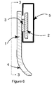
- FIG. 6 depicts a cross-sectional view of the drapery carrier of FIG. 1 in perpendicular engagement with an exemplary traverse-rod.
- a drapery carrier ( 1 ) comprises a post member ( 3 ) having a generally rectangular retaining plate ( 2 ).
- the carrier ( 1 ) also comprises an eye ( 4 ) for receiving a hook member (not shown) of a drape (not shown).
- the bottom of the carrier ( 1 ) is curved or bowed so that the weight of drapery suspended from eye ( 4 ) is approximately directly beneath the post member ( 3 ).
- the carrier ( 1 ) is configured to hang vertically and slide smoothly back and forth in a traverse-rod ( 5 ).
- the carrier ( 1 ) may be used to hold a pinch-pleated drape or curtain relative to a traverse-rod ( 5 ).
- the carrier ( 1 ) of the present example is further configured to slide along a slot ( 6 ) of the traverse-rod ( 5 ), such as for opening and closing of a drape.
- the slot ( 6 ) of a traverse-rod ( 5 ) is about 9/32 inch wide, and the traverse-rod is secured to a wall.
- the traverse-rod ( 5 ) is configured to carry a plurality of carriers ( 1 ) and cord and pulleys (not shown) for opening and closing drapery.
- the upper and lower ends of the retaining plate ( 2 ) are rounded so that the carrier ( 1 ) may rotate as it is drawn back and forth in the traverse-rod ( 5 ) as the drapery is opened and closed. Thus, the carrier ( 1 ) may rotate up to ninety degrees without falling out of the traverse-rod ( 5 ).
- Other suitable configurations and uses for carrier ( 1 ) and traverse-rod ( 5 ) will be apparent to those of ordinary skill in the art.
- the retaining plate ( 2 ) of the present example is sufficiently narrow (e.g., about 1 ⁇ 4 inch) that it can be inserted into a slot ( 6 ) of a traverse-rod ( 5 ) at the point where a broken carrier ( 1 ) needs to be replaced.
- the carrier ( 1 ) is rotated until its longitudinal axis is approximately aligned with the slot ( 6 ) in the traverse-rod ( 5 ).
- the retaining plate ( 2 ) and post member ( 3 ) are then inserted through the slot ( 6 ) of the traverse-rod ( 5 ).
- Such insertion is provided by movement in a direction generally perpendicular to the traverse-rod ( 5 ), instead of by movement in a direction generally parallel with the traverse-rod ( 5 ) as is typically necessary with a conventional carrier ( 10 ).
- the insertion of carrier ( 1 ) may thus be referred to as a “perpendicular insertion” (though longitudinal axis of the carrier ( 1 ) may be oriented parallel to the slot ( 6 ) of the traverse-rod ( 5 ) during the act of insertion).
- the carrier ( 1 ) is then rotated so that it hangs downward and the post member ( 3 ) is slidable along the slot ( 6 ) in the traverse-rod ( 5 ), such as is shown in FIG. 6 , ready to receive a drapery hanger hook.
- the term “generally rectangular” is intended to include configurations where the height of the retaining plate ( 2 ) is greater than the width of the retaining plate. As shown, the generally rectangular retaining plate ( 2 ) has substantially straight vertical sides that provide a height that is greater than the width provided by the generally curved horizontal sides of the retaining plate ( 2 ). However, it will be appreciated that an elliptical-shaped retaining plate ( 2 ) may also be considered “generally rectangular” as defined herein, as may retaining plates ( 2 ) having other shapes.
- the generally rectangular retaining plate ( 2 ) will have a width dimensioned to permit the retaining plate ( 2 ) to be inserted through the slot ( 6 ) of a traverse-rod ( 5 ) when the retaining plate ( 2 ) is at a first orientation (e.g., horizontal), and a height dimensioned to permit the retaining plate ( 2 ) to be slidably secured relative to the traverse-rod ( 5 ) when the retaining plate ( 2 ) is at a second orientation (e.g., vertical).
- a first orientation e.g., horizontal
- the improved carrier ( 1 ) of the present example may also be used for the initial installation of drapes.
- the carrier ( 1 ) may have the same overall dimensions as conventional carriers ( 10 ).
- a carrier ( 1 ) may be about 13 ⁇ 8 inches long and about 1 ⁇ 2 inch wide at it's widest point.
- the plate ( 2 ) may be about 1 ⁇ 2 inch long and about 1 ⁇ 4 inch wide, and rounded at the top and bottom.
- the post member ( 3 ) may be about 3/16 inch thick and have a diameter of about 7/32 inch. Eye ( 4 ) may have a diameter of about 3/16 inch.
- the carrier ( 1 ) may be produced using conventional rigid-plastic materials and casting techniques. Of course, it will be appreciated that any other suitable dimensions, configurations, materials, and methods of production may be used.
Landscapes
- Curtains And Furnishings For Windows Or Doors (AREA)
Abstract
A drapery carrier has a generally rectangular retaining plate. The width of the retaining plate is sufficiently narrow (e.g., about ¼ inch), in the dimension perpendicular to longitudinal axis of the carrier, so that it can be inserted through the horizontal slot in a drapery traverse rod when the carrier is aligned with its longitudinal axis parallel to the horizontal slot in the traverse rod. The length of the retaining plate is sufficiently long (e.g., about ½ inch) and rounded on the ends so that it prevents the carrier from falling out of the traverse rod when the carrier hangs vertically to carry a wire hook supporting a drapery pleat. The carrier may be made of cast rigid plastic with an eye to receive a wire drapery hook. The retaining plate is attached to the base of the carrier by a generally cylindrical slider.
Description
- Conventional drapery carriers (sometimes also referred to as “slides”) include plastic pieces on which pinch-pleated drapery is suspended by wire hooks. The carriers are pulled along a traverse-rod mounted horizontally above the window or doorway as the drapery is opened or closed by draw cords. Typically, each pleat of the drapery is suspended on a separate carrier. When the eye of the carrier, in which the wire hook is attached, breaks, the section of the drape previously supported by that carrier may hang down in an unsightly fashion, and the broken carrier may need to be replaced.
- Conventional designs for a drapery carrier include a circular retaining plate that does not permit a new carrier to be inserted into the traverse-rod at the specific position along the rod where the broken carrier needs to be replaced. An exemplary conventional drapery carrier (10) is shown in
FIG. 4 , and comprises a slider (20), a generally circular retaining plate (20), a cylindrical post member (30), and an eye (40). Often, when a carrier (10) breaks, the traverse-rod must be opened from an end; and such plastic carriers (10) must be removed one-by-one until the broken carrier (not shown) is reached. The broken carrier is removed, and a new carrier (10) is inserted, at the end of the traverse-rod. The remaining carriers (10) must then be reinserted in the traverse-rod one-by-one; and the draw-cord pulleys reinstalled at the end of the traverse-rod. Replacement of a broken drapery carrier may ultimately be a difficult, frustrating, time consuming, and sometimes dangerous task requiring standing on a chair or a ladder. - Embodiments of the present invention comprise a rigid plastic pinch-pleated drapery carrier that can be installed easily in a traverse-rod to replace a broken carrier. In the design of the present example the retaining plate is generally rectangular rather than generally circular and of a relatively narrow width (e.g., about ¼ inch), so that it can be inserted into the longitudinal slot in the traverse-rod generally at the point of the broken carrier without having to disassemble the suspension system to get to the point of the broken carrier. The broken carrier need not necessarily be removed and may be left to slide along the traverse-rod without interfering with the movement of the drapery as it is opened and closed. Embodiments of the drapery carrier may also be used for all the carriers in the initial installation of a drapery so that broken carriers may be easily removed if they ever need to be replaced.
- While the specification concludes with claims which particularly point out and distinctly claim the invention, it is believed the present invention will be better understood from the following description of certain examples taken in conjunction with the accompanying drawings, in which like reference numerals identify the same elements and in which:
-
FIG. 1 depicts a plan view of an exemplary embodiment of the drapery carrier of the present invention; -
FIG. 2 depicts a cross-sectional view of the drapery carrier ofFIG. 1 , taken along line 2-2 ofFIG. 1 ; -
FIG. 3 depicts a cross-sectional view of the drapery carrier ofFIG. 1 , taken along line 3-3 ofFIG. 1 ; -
FIG. 4 depicts a plan view of a prior art drapery carrier; -
FIG. 5 depicts a plan view of the drapery carrier ofFIG. 1 in parallel engagement with an exemplary traverse-rod; and -
FIG. 6 depicts a cross-sectional view of the drapery carrier ofFIG. 1 in perpendicular engagement with an exemplary traverse-rod. - The following description of certain examples of the invention should not be used to limit the scope of the present invention. Other examples, features, aspects, embodiments, and advantages of the invention will become apparent to those skilled in the art from the following description, which is by way of illustration, one of the best modes contemplated for carrying out the invention. As will be realized, the invention is capable of other different and obvious aspects, all without departing from the invention. Accordingly, the drawings and descriptions should be regarded as illustrative in nature and not restrictive.
- In the present example, and as shown in
FIGS. 1-3 and 5-6, a drapery carrier (1) comprises a post member (3) having a generally rectangular retaining plate (2). The carrier (1) also comprises an eye (4) for receiving a hook member (not shown) of a drape (not shown). As shown inFIGS. 3 and 6 , the bottom of the carrier (1) is curved or bowed so that the weight of drapery suspended from eye (4) is approximately directly beneath the post member (3). As shown inFIG. 6 , the carrier (1) is configured to hang vertically and slide smoothly back and forth in a traverse-rod (5). - By way of example only, the carrier (1) may be used to hold a pinch-pleated drape or curtain relative to a traverse-rod (5). The carrier (1) of the present example is further configured to slide along a slot (6) of the traverse-rod (5), such as for opening and closing of a drape. In one embodiment, the slot (6) of a traverse-rod (5) is about 9/32 inch wide, and the traverse-rod is secured to a wall. The traverse-rod (5) is configured to carry a plurality of carriers (1) and cord and pulleys (not shown) for opening and closing drapery. The upper and lower ends of the retaining plate (2) are rounded so that the carrier (1) may rotate as it is drawn back and forth in the traverse-rod (5) as the drapery is opened and closed. Thus, the carrier (1) may rotate up to ninety degrees without falling out of the traverse-rod (5). Other suitable configurations and uses for carrier (1) and traverse-rod (5) will be apparent to those of ordinary skill in the art.
- The retaining plate (2) of the present example is sufficiently narrow (e.g., about ¼ inch) that it can be inserted into a slot (6) of a traverse-rod (5) at the point where a broken carrier (1) needs to be replaced. To install the carrier (1) of the present example, and as shown in
FIG. 5 , the carrier (1) is rotated until its longitudinal axis is approximately aligned with the slot (6) in the traverse-rod (5). The retaining plate (2) and post member (3) are then inserted through the slot (6) of the traverse-rod (5). Such insertion is provided by movement in a direction generally perpendicular to the traverse-rod (5), instead of by movement in a direction generally parallel with the traverse-rod (5) as is typically necessary with a conventional carrier (10). The insertion of carrier (1) may thus be referred to as a “perpendicular insertion” (though longitudinal axis of the carrier (1) may be oriented parallel to the slot (6) of the traverse-rod (5) during the act of insertion). The carrier (1) is then rotated so that it hangs downward and the post member (3) is slidable along the slot (6) in the traverse-rod (5), such as is shown inFIG. 6 , ready to receive a drapery hanger hook. - As used herein to describe the configuration of the retaining plate (2), the term “generally rectangular” is intended to include configurations where the height of the retaining plate (2) is greater than the width of the retaining plate. As shown, the generally rectangular retaining plate (2) has substantially straight vertical sides that provide a height that is greater than the width provided by the generally curved horizontal sides of the retaining plate (2). However, it will be appreciated that an elliptical-shaped retaining plate (2) may also be considered “generally rectangular” as defined herein, as may retaining plates (2) having other shapes. Preferably, however, the generally rectangular retaining plate (2) will have a width dimensioned to permit the retaining plate (2) to be inserted through the slot (6) of a traverse-rod (5) when the retaining plate (2) is at a first orientation (e.g., horizontal), and a height dimensioned to permit the retaining plate (2) to be slidably secured relative to the traverse-rod (5) when the retaining plate (2) is at a second orientation (e.g., vertical).
- The improved carrier (1) of the present example may also be used for the initial installation of drapes. The carrier (1) may have the same overall dimensions as conventional carriers (10). By way of example only, a carrier (1) may be about 1⅜ inches long and about ½ inch wide at it's widest point. The plate (2) may be about ½ inch long and about ¼ inch wide, and rounded at the top and bottom. The post member (3) may be about 3/16 inch thick and have a diameter of about 7/32 inch. Eye (4) may have a diameter of about 3/16 inch. The carrier (1) may be produced using conventional rigid-plastic materials and casting techniques. Of course, it will be appreciated that any other suitable dimensions, configurations, materials, and methods of production may be used.
- Having shown and described various embodiments of the present invention, further adaptations of the methods and systems described herein may be accomplished by appropriate modifications by one of ordinary skill in the art without departing from the scope of the present invention. Several of such potential modifications have been mentioned, and others will be apparent to those skilled in the art. For instance, the examples, embodiments, geometries, materials, dimensions, ratios, steps, and the like discussed above are illustrative and are not required. Accordingly, the scope of the present invention should be considered in terms of the following claims and is understood not to be limited to the details of structure and operation shown and described in the specification and drawings.
Claims (17)
1. A drapery carrier, comprising:
(a) an upright member;
(b) a post member extending generally perpendicularly from the upright member; and
(c) a retaining plate positioned on the post member, wherein the retaining plate is generally rectangular, wherein the retaining plate is configured to be perpendicularly inserted through a slot in a traverse-rod when the upright member is oriented generally horizontally.
2. The drapery carrier of claim 1 , wherein the upright member has an eye configured to receive a hook member.
3. The drapery carrier of claim 1 , wherein the upright member has a generally bowed lower portion.
4. The drapery carrier of claim 1 , wherein the retaining plate has a pair of substantially straight vertical sides.
5. The drapery carrier of claim 4 , wherein the retaining plate has a pair of generally curved horizontal sides.
6. The drapery carrier of claim 1 , wherein the retaining plate is about ¼ inch wide and about ½ inch long.
7. The drapery carrier of claim 1 , wherein the drapery carrier is formed of plastic.
8. The drapery carrier of claim 7 , wherein the plastic is cast.
9. The drapery carrier of claim 1 , wherein the retaining plate is oriented generally parallel with the upright member.
10. The drapery carrier of claim 1 , wherein the retaining plate is configured to slidably retain the drapery carrier relative to a traverse-rod when the upright member is oriented generally vertically.
11. A drapery carrier system, comprising:
(a) a traverse-rod, wherein the traverse-rod has a horizontal slot, wherein the traverse-rod is configured to receive a plurality of drapery carriers; and
(b) a drapery carrier, wherein the drapery carrier comprises:
(i) an upright member,
(ii) a post member extending generally perpendicularly from the upright member, and
(iii) a retaining plate positioned on the post member, wherein the retaining plate is generally rectangular, wherein the retaining plate is configured to be perpendicularly inserted through the horizontal slot of the traverse-rod when the upright member is oriented generally horizontally.
12. The drapery carrier system of claim 11 , wherein the horizontal slot has a height, wherein the retaining plate has a width, wherein the width of the retaining plate is less than the height of the horizontal slot.
13. The drapery carrier system of claim 12 , wherein the retaining plate has a height, wherein the height of the retaining plate is greater than the height of the slot.
14. A method of hanging a drapery carrier, the method comprising:
(a) providing a horizontal traverse-rod, wherein the traverse-rod has a horizontal slot, wherein the traverse-rod is configured to receive a plurality of drapery carriers;
(b) providing a drapery carrier, wherein the drapery carrier comprises:
(i) an upright member,
(ii) a post member extending generally perpendicularly from the upright member, and
(iii) a retaining plate positioned on the post member, wherein the retaining plate is generally rectangular, wherein the retaining plate is configured to be perpendicularly inserted through the horizontal slot of the traverse-rod when the upright member is oriented generally horizontally;
(c) orienting the drapery carrier such that the upright member is oriented generally horizontally;
(d) perpendicularly inserting the retaining plate into the horizontal slot of the traverse-rod; and
(e) orienting the drapery carrier such that the upright member is oriented generally vertically.
15. The method of claim 14 , the method further comprising removing a damaged drapery carrier from the traverse-rod.
16. The method of claim 15 , wherein the act of removing a damaged drapery carrier comprises sliding the damaged drapery carrier out of an end of the traverse-rod.
17. The method of claim 14 , wherein the method is performed on a traverse-rod having no drapery carriers before the method is performed.
Priority Applications (1)
| Application Number | Priority Date | Filing Date | Title |
|---|---|---|---|
| US11/548,475 US20080098570A1 (en) | 2006-10-11 | 2006-10-11 | Drapery carrier |
Applications Claiming Priority (1)
| Application Number | Priority Date | Filing Date | Title |
|---|---|---|---|
| US11/548,475 US20080098570A1 (en) | 2006-10-11 | 2006-10-11 | Drapery carrier |
Publications (1)
| Publication Number | Publication Date |
|---|---|
| US20080098570A1 true US20080098570A1 (en) | 2008-05-01 |
Family
ID=39328417
Family Applications (1)
| Application Number | Title | Priority Date | Filing Date |
|---|---|---|---|
| US11/548,475 Abandoned US20080098570A1 (en) | 2006-10-11 | 2006-10-11 | Drapery carrier |
Country Status (1)
| Country | Link |
|---|---|
| US (1) | US20080098570A1 (en) |
Cited By (2)
| Publication number | Priority date | Publication date | Assignee | Title |
|---|---|---|---|---|
| USD746078S1 (en) * | 2000-07-17 | 2015-12-29 | Zahner Design Group, Ltd. | Shower curtain |
| US11746590B2 (en) | 2017-01-25 | 2023-09-05 | Hunter Douglas Inc. | Vertical cellular drape for an architectural structure |
Citations (5)
| Publication number | Priority date | Publication date | Assignee | Title |
|---|---|---|---|---|
| US2848734A (en) * | 1953-07-23 | 1958-08-26 | Ault Hyman Jay | Drapery carrier |
| US3055420A (en) * | 1956-07-30 | 1962-09-25 | Del Faro | Drapery hardware |
| US3134132A (en) * | 1961-10-23 | 1964-05-26 | Graber Mfg Company Inc | Drapery rod fixture |
| US3262148A (en) * | 1964-01-07 | 1966-07-26 | Morris A Saltz | Drapery carrier |
| US6182739B1 (en) * | 1997-12-19 | 2001-02-06 | Gary F. Jones | Snap mounted drapery system |
-
2006
- 2006-10-11 US US11/548,475 patent/US20080098570A1/en not_active Abandoned
Patent Citations (5)
| Publication number | Priority date | Publication date | Assignee | Title |
|---|---|---|---|---|
| US2848734A (en) * | 1953-07-23 | 1958-08-26 | Ault Hyman Jay | Drapery carrier |
| US3055420A (en) * | 1956-07-30 | 1962-09-25 | Del Faro | Drapery hardware |
| US3134132A (en) * | 1961-10-23 | 1964-05-26 | Graber Mfg Company Inc | Drapery rod fixture |
| US3262148A (en) * | 1964-01-07 | 1966-07-26 | Morris A Saltz | Drapery carrier |
| US6182739B1 (en) * | 1997-12-19 | 2001-02-06 | Gary F. Jones | Snap mounted drapery system |
Cited By (3)
| Publication number | Priority date | Publication date | Assignee | Title |
|---|---|---|---|---|
| USD746078S1 (en) * | 2000-07-17 | 2015-12-29 | Zahner Design Group, Ltd. | Shower curtain |
| USD981138S1 (en) | 2000-07-17 | 2023-03-21 | Zahner Design Group, Ltd. | Shower curtain |
| US11746590B2 (en) | 2017-01-25 | 2023-09-05 | Hunter Douglas Inc. | Vertical cellular drape for an architectural structure |
Similar Documents
| Publication | Publication Date | Title |
|---|---|---|
| US7699278B2 (en) | Curtain rods and brackets | |
| CN102215724A (en) | Valance | |
| US10278529B2 (en) | Room darkening curtain rods including removable finials | |
| CN105492705B (en) | Installation of ceiling formula baffle system | |
| TWI437946B (en) | Slide assembly with quick-mount system | |
| DK2784235T3 (en) | Suspended ceiling system suspended ceiling and the use of the suspended ceiling system for making the suspended ceiling | |
| US10619414B2 (en) | Pivot mount for roller shade | |
| US11864679B1 (en) | Display clips | |
| CN106679136B (en) | Courtyard machine panel and air conditioning device | |
| US8474168B2 (en) | Adjustable sign frame and method of using the same | |
| US8240489B2 (en) | Traverse rod assembly | |
| US20080098570A1 (en) | Drapery carrier | |
| US8925122B2 (en) | Fully articulable shower curtain rod | |
| JP5919330B2 (en) | Wire interlocking sliding door device | |
| WO2011038421A1 (en) | Curtain rail supporting bracket | |
| JP4187628B2 (en) | Spiral spring type balancer device and method for installing shoji using the same | |
| KR100730339B1 (en) | Load regulator of roll screen | |
| KR20090027839A (en) | Curtain wave shaping mechanism | |
| JP4278484B2 (en) | Curtain hanger | |
| US9044114B1 (en) | Snap-in replacement curtain hanger and method | |
| KR200478964Y1 (en) | Event and Promotional Flags Suspension | |
| JP2008161613A (en) | Suspended lifting device | |
| US20210212497A1 (en) | Suspension system. | |
| CN110424042B (en) | Electrophoresis spraying processing part anti-drop hanger with adjustable | |
| CN210828746U (en) | Window opening supporting and positioning mechanism |
Legal Events
| Date | Code | Title | Description |
|---|---|---|---|
| STCB | Information on status: application discontinuation |
Free format text: ABANDONED -- FAILURE TO RESPOND TO AN OFFICE ACTION |